EP2575141B1 - Système de refroidissement à chambre de condensation - Google Patents
Système de refroidissement à chambre de condensation Download PDFInfo
- Publication number
- EP2575141B1 EP2575141B1 EP12006588.3A EP12006588A EP2575141B1 EP 2575141 B1 EP2575141 B1 EP 2575141B1 EP 12006588 A EP12006588 A EP 12006588A EP 2575141 B1 EP2575141 B1 EP 2575141B1
- Authority
- EP
- European Patent Office
- Prior art keywords
- condensation chamber
- cooling system
- water
- cooling
- condensation
- Prior art date
- Legal status (The legal status is an assumption and is not a legal conclusion. Google has not performed a legal analysis and makes no representation as to the accuracy of the status listed.)
- Not-in-force
Links
Images

Classifications
-
- G—PHYSICS
- G21—NUCLEAR PHYSICS; NUCLEAR ENGINEERING
- G21C—NUCLEAR REACTORS
- G21C9/00—Emergency protection arrangements structurally associated with the reactor, e.g. safety valves provided with pressure equalisation devices
- G21C9/004—Pressure suppression
- G21C9/012—Pressure suppression by thermal accumulation or by steam condensation, e.g. ice condensers
-
- F—MECHANICAL ENGINEERING; LIGHTING; HEATING; WEAPONS; BLASTING
- F28—HEAT EXCHANGE IN GENERAL
- F28D—HEAT-EXCHANGE APPARATUS, NOT PROVIDED FOR IN ANOTHER SUBCLASS, IN WHICH THE HEAT-EXCHANGE MEDIA DO NOT COME INTO DIRECT CONTACT
- F28D15/00—Heat-exchange apparatus with the intermediate heat-transfer medium in closed tubes passing into or through the conduit walls ; Heat-exchange apparatus employing intermediate heat-transfer medium or bodies
-
- G—PHYSICS
- G21—NUCLEAR PHYSICS; NUCLEAR ENGINEERING
- G21C—NUCLEAR REACTORS
- G21C15/00—Cooling arrangements within the pressure vessel containing the core; Selection of specific coolants
- G21C15/18—Emergency cooling arrangements; Removing shut-down heat
-
- G—PHYSICS
- G21—NUCLEAR PHYSICS; NUCLEAR ENGINEERING
- G21C—NUCLEAR REACTORS
- G21C15/00—Cooling arrangements within the pressure vessel containing the core; Selection of specific coolants
- G21C15/24—Promoting flow of the coolant
- G21C15/243—Promoting flow of the coolant for liquids
-
- G—PHYSICS
- G21—NUCLEAR PHYSICS; NUCLEAR ENGINEERING
- G21C—NUCLEAR REACTORS
- G21C15/00—Cooling arrangements within the pressure vessel containing the core; Selection of specific coolants
- G21C15/24—Promoting flow of the coolant
- G21C15/26—Promoting flow of the coolant by convection, e.g. using chimneys, using divergent channels
-
- G—PHYSICS
- G21—NUCLEAR PHYSICS; NUCLEAR ENGINEERING
- G21C—NUCLEAR REACTORS
- G21C19/00—Arrangements for treating, for handling, or for facilitating the handling of, fuel or other materials which are used within the reactor, e.g. within its pressure vessel
- G21C19/28—Arrangements for introducing fluent material into the reactor core; Arrangements for removing fluent material from the reactor core
-
- G—PHYSICS
- G21—NUCLEAR PHYSICS; NUCLEAR ENGINEERING
- G21D—NUCLEAR POWER PLANT
- G21D1/00—Details of nuclear power plant
- G21D1/02—Arrangements of auxiliary equipment
-
- G—PHYSICS
- G21—NUCLEAR PHYSICS; NUCLEAR ENGINEERING
- G21D—NUCLEAR POWER PLANT
- G21D3/00—Control of nuclear power plant
- G21D3/04—Safety arrangements
-
- Y—GENERAL TAGGING OF NEW TECHNOLOGICAL DEVELOPMENTS; GENERAL TAGGING OF CROSS-SECTIONAL TECHNOLOGIES SPANNING OVER SEVERAL SECTIONS OF THE IPC; TECHNICAL SUBJECTS COVERED BY FORMER USPC CROSS-REFERENCE ART COLLECTIONS [XRACs] AND DIGESTS
- Y02—TECHNOLOGIES OR APPLICATIONS FOR MITIGATION OR ADAPTATION AGAINST CLIMATE CHANGE
- Y02E—REDUCTION OF GREENHOUSE GAS [GHG] EMISSIONS, RELATED TO ENERGY GENERATION, TRANSMISSION OR DISTRIBUTION
- Y02E30/00—Energy generation of nuclear origin
- Y02E30/30—Nuclear fission reactors
Definitions
- the invention relates to a condensation chamber with the condensation chamber cooling system comprising a condensation chamber for a boiling water reactor and at least one is arranged outside the condensation chamber heat exchanger.
- the reactor core is covered with water in a boiling water reactor, sufficient cooling can be assumed.
- boiling water reactors the after-decay heat generated after a shutdown is removed by boiling the water surrounding the fuel elements. By evaporating the water, a cooling effect of the fuel elements corresponding to the respective evaporation energy takes place.
- the resulting steam is blown off via safety valves in a water reservoir outside the pressure or safety container in a so-called condensation chamber and condensed there.
- the lost by blowing off steam into the condensation chamber water inventory of the pressure vessel is typically performed by active feed systems from the condensation chamber back into the pressure vessel.
- EP 0476 563 A2 discloses a nuclear reactor with reactor pressure vessel and a cooling system.
- the patent document DE 44 16 140 A1 discloses a nuclear reactor plant having a containment surrounding a reactor pressure vessel and forming therein a dry well, which usually contains a non-condensable gas such as nitrogen.
- a conventional reactor core is arranged in Water is immersed and the water is heated to generate steam, which is discharged from the pressure vessel.
- the patent document US Pat. No. 6,285,727 B1 discloses a nuclear reactor plant having a light water reactor and a containment shell having an upper space and a lower space, the lower space being separated from the upper space by a partition and intended to receive a refrigerant, and the light water reactor having a reactor vessel including a reactor Reactor core accommodates and is arranged in the upper space.
- cooling systems for discharging the condensation heat introduced into the condensation chamber are of an active nature, that is to say that active components such as circulation pumps for the cooling medium require water.
- active components such as circulation pumps for the cooling medium require water.
- a condensation chamber cooling system of the aforementioned type This is characterized in that an elongate cooling module is provided in the condensation chamber, with an evaporation space located in its upper region, the cooling module being arranged in the condensation chamber such that the evaporation space above a maximum level of a water reservoir is located in the condensation chamber.
- the condensation chamber cooling system comprises at least one riser and one downcomer, which open with their respective upper ends in the evaporation space and with their respective lower ends in the condensation chamber below a minimum level of the water mask, wherein a first pressure line from the evaporation space to the heat exchanger is provided and there a second pressure line, which opens in the condensation chamber preferably below the minimum level, so that a passive closed cooling circuit is formed by the condensation chamber, the pressure lines, the cooling module and the heat exchanger.
- the basic idea of the invention is to provide a condensation chamber cooling system with natural circulation of the coolant or water, thus avoiding an active circulation pump and thus reducing the probability of failure of the cooling system.
- the riser downpipe is located in preferably approximately vertical arrangement completely within the condensation chamber and protrudes with its lower end into the liquid condensation chamber water.
- the liquid water within the riser down pipe also heats up to the temperature within the condensation chamber, which may be configured, for example, as a torus-like ring around the lower portion of the containment.
- the water level within the riser downpipe is geodetically higher than the water level or the level of the condensing chamber.
- the static pressure in the evaporation chamber at a height difference of for example 2m is correspondingly lower. If the condensation chamber water is at saturation temperature, as explained above, the water will boil in the evaporation space located above the water level of the condensation chamber or the corresponding pipe sections due to the lower static pressure prevailing there.
- the boiling process leads to a cooling of the water located in the evaporation chamber on the one hand and a vapor formation on the other.
- the riser downpipe is designed so that water is passed to saturation temperature via the riser pipe in the evaporation space and is cooled there by the boiling process with formation of steam.
- the cooled water which then has a correspondingly higher density than the water to saturation temperature, is then returned via the downcomer to the water reservoir within the condensation chamber.
- their respective lower orifices are preferably offset relative to one another.
- the resulting vapor in the evaporation chamber is passed from there through the first pressure line, a steam line, preferably to a condenser comprising a heat exchanger, where the steam gives off by condensation heat to the heat exchanger. This then dissipates the heat directly or indirectly to an external heat sink, for example to a cooling tower.
- the heat exchanger can also have a water reservoir which absorbs the condensation heat and dissipates it by means of a further water circulation.
- the condensate formed during condensation is conducted via the second pressure line, a condensate line, from the condenser back into the condensation chamber.
- the heat exchanger is arranged on such a geodetic height above the condensation chamber, that the condensate alone flows back into the condensation chamber via the condensate line, which is preferably designed with a constant gradient.
- the condensate line which is preferably designed with a constant gradient.
- the drop tube is nested in the riser, so that an outer riser and an inner downpipe extending therein are formed. This proves to be particularly favorable as a manufacturing technology and also allows a high mechanical stability of the cooling module according to the invention.
- the heat exchanger comprises an evaporation condenser.
- a discharge line opens below the minimum filling level in the condensation chamber.
- This line is intended to introduce vapor released from an associated boiling water reactor via a drain valve into the water reservoir of the condensation chamber.
- this line is branched at its end so as to allow an improved penetration of the water with the steam. As a result, the condensation of the vapor and thus also the effectiveness of the condensation chamber cooling system is improved.
- a vacuum pump acting on the cooling circuit is provided.
- the passively operating condensation chamber cooling system is thus evacuated. This ensures that only liquid or gaseous water is within the pipe system or cooling circuit.
- the vacuum pump remains in operation to prevent accumulation of non-condensable gases.
- the at least one heat exchanger is arranged geodetically above the condensation chamber. This allows for a correspondingly falling falling condensate line a purely gravity-driven return of the condensate in the condensation chamber, so that no pumping means are required.
- the minimum filling level of the condensation chamber preferably corresponds at least approximately to its maximum filling level.
- the cooling properties of the condensation chamber cooling system are thereby kept constant. Such approximately the same level level is achieved by appropriate controlled recycling of Kondensationshuntwasser in the reactor.
- a particularly preferred variant of the condensation chamber cooling system according to the invention is characterized in that at least one additional active cooling circuit is provided for the removal of waste heat from the condensation chamber.
- a total cooling system for the condensation chamber is created, which is diverse, so based on different working cooling systems.
- the simultaneous failure of diversely operating cooling systems is less likely than the simultaneous failure of similar cooling systems.
- the safety of such a total cooling system is further increased.
- at least the active cooling system is also designed to be redundant, so from several possibly similar and parallel operating individual systems, the total cooling capacity is below the maximum expected cooling capacity, so that despite a possible failure of a system safe cooling is guaranteed.
- the additional use of a passive system described above further increases the reliability, the individual failure probability is particularly low due to the passive principle.
- a pumping system for the return of water in the condensation chamber to the associated boiling water reactor is provided. This is necessary as mentioned above to maintain the water inventory of the boiling water reactor and may also be considered part of the refrigeration system of the present invention.
- the heat exchanger according to the invention is intended to dissipate waste heat to the environment. This can optionally take place via the interposition of further cooling circuits and heat exchangers, wherein a cooling tower represents a preferred heat sink for the final heat release to the environment.
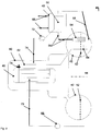
- Fig. 1 shows a first exemplary cooling module 10 in a sectional view.
- an evaporation chamber 12 is provided in its interior.
- the riser is indicated as rotationally symmetrical about a rotation axis 28, but any other cross-sectional shapes are conceivable, for example rectangular or not interleaved variants .
- a connection 22 for a first pressure line or steam line is arranged, which leads to a capacitor, not shown.
- the cooling module protrudes in its lower region into the water of a condenser, not shown, whose maximum level is indicated by the dashed line with the reference numeral 14 and whose minimum level is indicated by the dashed line by the reference numeral 16. This ensures that condensation chamber water can always flow into the riser pipe, as indicated by the arrow with the reference numeral 24.
- the water level of the water located in the evaporation space is geodetically higher than the maximum and minimum level in the condensation chamber, as within which the cooling module 10 is to be assumed arranged. It is also to be assumed that the condensation chamber water has saturation temperature, that is, that the liquid and the overlying gaseous phase of the water are in saturation equilibrium and that the cooling module 10 has likewise assumed this temperature. Due to the geodetically higher arrangement of the evaporation chamber 12, the water therein is boiling under the mentioned boundary conditions.
- the boiling process also generates steam, which is then conducted through the connection 22 in the upper region of the evaporation space to a condenser, not shown, where the heat is released by condensation in an equally effective manner.
- a suitable material for a cooling module according to the invention is, for example, stainless steel, wherein a cooling module - depending on the design - for example, may have a height of, for example, 1 m to 2 m. This height difference is sufficient to cause boiling in the evaporation space 12 at saturation temperature conditions.
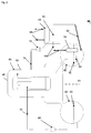
- Fig. 2 shows an exemplary boiling water reactor with Kondensationsschkühlsystem in a schematic view 40.
- a boiling water reactor 46 is disposed within a security or pressure vessel 60, which has, for example, a height of 10m.
- a ring-like condensation chamber 42 is provided in the form of a torus about this, arranged around a rotation axis 44, which is connected to the pressure vessel 60 via corresponding pressure-resistant pipe connections.
- the condensation chamber is filled up to a level 52 with condensation chamber water.
- a drain line 62 closable by means of a drain valve 76 leads into the condensation chamber 42 and flows below the fill level 52 into a distributor 64.
- the latter ensures a particularly good penetration of the condensation chamber water from steam flowing through the drain line 62.
- Steam is then introduced from the boiling water reactor 46 into the drain line 62 when it is created during the reactor cooling and with it too high a pressure. This steam leads to condensation in the condensation chamber to a heating of the condensation chamber water therein.
- a cooling module 54 Vertically disposed within the condensation chamber 42 and into the condensation chamber water projecting is a cooling module 54. This has an evaporator chamber and a riser down pipe, wherein water rises through the riser into the evaporator chamber, there boiling with the release of steam, is cooled and by the Downpipe falls back down again. Thus, a cooling of the condensation chamber water is effected. It is thus formed another natural cooling circuit.
- the resulting vapor is conducted from the evaporator chamber via a first pressure line 56 to a heat exchanger 48, which in particular has a capacitor 50.
- a heat exchanger 48 which in particular has a capacitor 50.
- the steam is transferred with the release of heat in the liquid water state and led back from the condenser 50 via a steadily falling second pressure line 58 back into the condensation chamber 42, which is done solely by gravity.
- the heat exchanger 48 is in turn connected via corresponding inlet and outlet lines directly or indirectly with a heat sink for heat dissipation to the environment, such as a cooling tower.
- a vacuum pump 72 having a return line 74 acting on the cooling circuit is provided to evacuate the passively operating condensation chamber cooling system during normal plant operation. This ensures that only liquid or gaseous water is within the pipe system or cooling circuit. During the request, the vacuum pump 72 remains in operation to prevent accumulation of non-condensable gases.
- condensation water can be back into the boiling water reactor 46, so that its water inventory is maintained despite the discharge of steam into the condensation chamber 42.
Landscapes
- Engineering & Computer Science (AREA)
- Physics & Mathematics (AREA)
- General Engineering & Computer Science (AREA)
- Plasma & Fusion (AREA)
- High Energy & Nuclear Physics (AREA)
- Thermal Sciences (AREA)
- Mechanical Engineering (AREA)
- Business, Economics & Management (AREA)
- Emergency Management (AREA)
- Structure Of Emergency Protection For Nuclear Reactors (AREA)
Claims (10)
- Chambre de condensation comprenant un système de refroidissement pour chambre de condensation, comprenant- une chambre de condensation (42) pour réacteur à eau bouillante (46) et- au moins un échangeur de chaleur (48) disposé à l'extérieur de la chambre de condensation (42),caractérisée en ce que- un module de refroidissement allongé (10, 54) est prévu dans la chambre de condensation (42), lequel comprend- dans sa région supérieure, un espace d'évaporation (12), le module de refroidissement (10, 54) étant disposé dans la chambre de condensation (42) de telle sorte que l'espace d'évaporation (12) soit situé au-dessus d'un niveau de remplissage maximal (14) de la chambre de condensation (42),- au moins un tube montant (18) et un tube descendant (20) qui débouchent avec leur extrémité supérieure respective dans l'espace d'évaporation (12) et avec leur extrémité inférieure respective dans la chambre de condensation (42) en dessous d'un niveau de remplissage minimal (16),une première conduite de pression (56) allant de l'espace d'évaporation (12) à l'échangeur de chaleur (48) étant prévue et partant de là, une deuxième conduite de pression (58) qui débouche dans la chambre de condensation (42), de telle sorte qu'un circuit de refroidissement fermé passif soit formé par la chambre de condensation (42), les conduites de pression (56, 58), le module de refroidissement (10, 54) et l'échangeur de chaleur (48).
- Chambre de condensation comprenant un système de refroidissement pour chambre de condensation selon la revendication 1, caractérisée en ce que le tube descendant (20) est emboîté dans le tube montant (18).
- Chambre de condensation comprenant un système de refroidissement pour chambre de condensation selon l'une quelconque des revendications 1 et 2, caractérisée en ce que l'échangeur de chaleur (48) comprend un condenseur d'évaporation (50).
- Chambre de condensation comprenant un système de refroidissement pour chambre de condensation selon l'une quelconque des revendications précédentes, caractérisée en ce qu'une conduite de purge (62) débouche en dessous du niveau de remplissage minimal (16) dans la chambre de condensation (42).
- Chambre de condensation comprenant un système de refroidissement pour chambre de condensation selon l'une quelconque des revendications précédentes, caractérisée en ce qu'une pompe à vide (72) agissant sur le circuit de refroidissement est prévue.
- Chambre de condensation comprenant un système de refroidissement pour chambre de condensation selon l'une quelconque des revendications précédentes, caractérisée en ce que l'au moins un échangeur de chaleur (48) est disposé géodésiquement au-dessus de la chambre de condensation (42).
- Chambre de condensation comprenant un système de refroidissement pour chambre de condensation selon l'une quelconque des revendications précédentes, caractérisée en ce que le niveau de remplissage minimal (16) correspond au moins approximativement au niveau de remplissage maximal (18).
- Chambre de condensation comprenant un système de refroidissement pour chambre de condensation selon l'une quelconque des revendications précédentes, caractérisée en ce qu'un circuit de refroidissement actif supplémentaire est prévu pour évacuer la chaleur perdue hors de la chambre de condensation (42).
- Chambre de condensation comprenant un système de refroidissement pour chambre de condensation selon l'une quelconque des revendications précédentes, caractérisée en ce qu'un système de pompe (68, 70) est prévu pour la recirculation de l'eau se trouvant dans la chambre de condensation (42) dans le réacteur à eau bouillante associé (46).
- Chambre de condensation comprenant un système de refroidissement pour chambre de condensation selon l'une quelconque des revendications précédentes, caractérisée en ce que l'échangeur de chaleur (48) est prévu pour évacuer la chaleur perdue vers l'environnement.
Applications Claiming Priority (1)
| Application Number | Priority Date | Filing Date | Title |
|---|---|---|---|
| DE102011115177A DE102011115177B3 (de) | 2011-09-28 | 2011-09-28 | Kondensationskammerkühlsystem |
Publications (3)
| Publication Number | Publication Date |
|---|---|
| EP2575141A2 EP2575141A2 (fr) | 2013-04-03 |
| EP2575141A3 EP2575141A3 (fr) | 2015-07-01 |
| EP2575141B1 true EP2575141B1 (fr) | 2016-03-30 |
Family
ID=46509787
Family Applications (1)
| Application Number | Title | Priority Date | Filing Date |
|---|---|---|---|
| EP12006588.3A Not-in-force EP2575141B1 (fr) | 2011-09-28 | 2012-09-20 | Système de refroidissement à chambre de condensation |
Country Status (5)
| Country | Link |
|---|---|
| US (1) | US9194629B2 (fr) |
| EP (1) | EP2575141B1 (fr) |
| JP (1) | JP6022286B2 (fr) |
| DE (1) | DE102011115177B3 (fr) |
| ES (1) | ES2576288T3 (fr) |
Cited By (1)
| Publication number | Priority date | Publication date | Assignee | Title |
|---|---|---|---|---|
| DE102017008253B3 (de) * | 2017-09-01 | 2018-12-06 | Westinghouse Electric Germany Gmbh | Sicherheitsbehälterkühlsystem |
Families Citing this family (6)
| Publication number | Priority date | Publication date | Assignee | Title |
|---|---|---|---|---|
| US9368241B2 (en) | 2012-06-29 | 2016-06-14 | Ge-Hitachi Nuclear Energy Americas Llc | System and method for processing and storing post-accident coolant |
| US9406407B2 (en) * | 2012-12-11 | 2016-08-02 | Ge-Hitachi Nuclear Energy Americas Llc | Radioactive capture system for severe accident containment of light water reactors (LWRS), and method thereof |
| KR101545085B1 (ko) | 2013-06-19 | 2015-08-18 | 한국원자력연구원 | 원자로 격납구조물 장기 냉각 시스템 |
| JP5853054B2 (ja) | 2013-06-19 | 2016-02-09 | コリア アトミック エナジー リサーチ インスティチュート | 原子炉格納構造物の冷却システム |
| KR101669765B1 (ko) * | 2015-07-24 | 2016-10-26 | 이창건 | 원자력 발전소의 증기를 이용한 냉각매체 생성장치 및 그 냉각방법 |
| CN111785399B (zh) * | 2020-07-06 | 2023-06-20 | 武汉第二船舶设计研究所(中国船舶重工集团公司第七一九研究所) | 一种用于海洋核动力平台热量导出的系统 |
Family Cites Families (18)
| Publication number | Priority date | Publication date | Assignee | Title |
|---|---|---|---|---|
| US3397113A (en) * | 1966-05-10 | 1968-08-13 | Chicago Bridge & Iron Co | Modular suppression tanks for nuclear containment structures |
| US3431168A (en) * | 1967-06-26 | 1969-03-04 | Gen Electric | Reactor cooling system |
| DE2932815A1 (de) * | 1979-08-13 | 1981-03-26 | Kraftwerk Union AG, 45473 Mülheim | Siedewasserreaktor |
| JPS63109394A (ja) * | 1986-10-27 | 1988-05-14 | 株式会社東芝 | 原子炉格納容器保護装置 |
| JPS63212892A (ja) * | 1987-02-28 | 1988-09-05 | 株式会社日立製作所 | 可搬式クエンチヤ型フイルタベントシステム |
| JPH01199192A (ja) * | 1988-02-04 | 1989-08-10 | Nippon Atom Ind Group Co Ltd | 格納容器保護装置 |
| US4998509A (en) * | 1989-05-11 | 1991-03-12 | General Electric Company | Passive heat removal from containment |
| US4986956A (en) * | 1989-11-27 | 1991-01-22 | Stone & Webster Engineering Corporation | Passive nuclear power plant containment system |
| US5223208A (en) * | 1990-08-14 | 1993-06-29 | Moritaka Ishimaru | Nuclear power generation system and its construction method |
| JP2507694B2 (ja) * | 1990-09-17 | 1996-06-12 | 株式会社日立製作所 | 原子炉設備 |
| JPH04128693A (ja) * | 1990-09-20 | 1992-04-30 | Hitachi Ltd | 原子炉格納容器 |
| US5295168A (en) * | 1993-04-15 | 1994-03-15 | General Electric Company | Pressure suppression containment system |
| SE9401559L (sv) * | 1993-05-07 | 1994-11-08 | Gen Electric | Passiv blandare |
| SE508995C2 (sv) * | 1997-03-07 | 1998-11-23 | Asea Atom Ab | Kärnreaktoranläggning |
| US6069930A (en) * | 1997-06-27 | 2000-05-30 | General Electric Company | Modified passive containment cooling system for a nuclear reactor |
| US8170173B2 (en) * | 2007-11-15 | 2012-05-01 | The State Of Oregon Acting By And Through The State Board Of Higher Education On Behalf Of Oregon State University | Passive emergency feedwater system |
| KR100966854B1 (ko) * | 2009-01-14 | 2010-06-29 | 한국원자력연구원 | 부분잠김형 열교환기를 사용하는 소듐냉각 고속로의 완전 피동형 잔열제거계통 |
| DE102010035955A1 (de) * | 2010-08-31 | 2012-03-01 | Westinghouse Electric Germany Gmbh | Brennelementlagerbecken mit Kühlsystem |
-
2011
- 2011-09-28 DE DE102011115177A patent/DE102011115177B3/de not_active Expired - Fee Related
-
2012
- 2012-09-20 EP EP12006588.3A patent/EP2575141B1/fr not_active Not-in-force
- 2012-09-20 ES ES12006588.3T patent/ES2576288T3/es active Active
- 2012-09-28 US US13/630,789 patent/US9194629B2/en not_active Expired - Fee Related
- 2012-09-28 JP JP2012216404A patent/JP6022286B2/ja not_active Expired - Fee Related
Cited By (1)
| Publication number | Priority date | Publication date | Assignee | Title |
|---|---|---|---|---|
| DE102017008253B3 (de) * | 2017-09-01 | 2018-12-06 | Westinghouse Electric Germany Gmbh | Sicherheitsbehälterkühlsystem |
Also Published As
| Publication number | Publication date |
|---|---|
| DE102011115177B3 (de) | 2012-07-12 |
| JP6022286B2 (ja) | 2016-11-09 |
| EP2575141A2 (fr) | 2013-04-03 |
| JP2013072879A (ja) | 2013-04-22 |
| US9194629B2 (en) | 2015-11-24 |
| US20130140005A1 (en) | 2013-06-06 |
| EP2575141A3 (fr) | 2015-07-01 |
| ES2576288T3 (es) | 2016-07-06 |
Similar Documents
| Publication | Publication Date | Title |
|---|---|---|
| EP2575141B1 (fr) | Système de refroidissement à chambre de condensation | |
| EP2423925B1 (fr) | Bassin de stockage d'éléments combustibles avec system de refroidissement | |
| DE68906727T2 (de) | Passives volldrucksystem zur spaltzonennotkuehlung und zur nachwaermeabfuhr fuer wassergekuehlte kernreaktoren. | |
| DE69110810T2 (de) | Kernreaktoranlage mit passiver Kühlung. | |
| EP2095370A1 (fr) | Installation technique nucléaire et procédé d'utilisation d'une installation technique nucléaire | |
| DE1881622U (de) | Vorrichtung zur dampferzeugung mit einem atomreaktor als waermequelle. | |
| DE3435255A1 (de) | Kernreaktoranlage mit einem ht-kleinreaktor mit kugelfoermigen brennelementen | |
| WO2018011363A1 (fr) | Système de récepteur de rayonnement haute température | |
| DE102008013933A1 (de) | Verfahren und Vorrichtung zum Abtrennen eines Neutronenabsorbers von einem Kühlmittel eines Kühlkreislaufes | |
| DE102012213489A1 (de) | Wärmeabfuhrsystem für eine kerntechnische Anlage | |
| EP0598787B1 (fr) | Systeme d'elimination de la chaleur residuelle par le cote secondaire pour les reacteurs nucleaires a eau sous pression | |
| EP1053550B1 (fr) | Accumulateur de pression et procede de mise a disposition d'un fluide sous pression | |
| DE69417267T2 (de) | Passives system zur nachzerfallwaermeabfuhr und zur druckentlastung fuer kernreaktoren | |
| DE2554180A1 (de) | Kernreaktoranlage | |
| DE102017008253B3 (de) | Sicherheitsbehälterkühlsystem | |
| DE102012007210B4 (de) | Verfahren und Vorrichtung zur thermischen Speicherung von Elektroenergie | |
| EP1576331B1 (fr) | Condenseur avec systeme de deaeration/degazage pour centrale thermique | |
| DE69405973T2 (de) | Kondensator für mit unkondensierbaren Gasen gemischten Dampf, ausgelegt für Naturumlauf in Kernreaktorschutzsystemen | |
| DE3701604C2 (fr) | ||
| EP0734028A1 (fr) | Enceinte de confinement d'un réacteur nucléaire | |
| EP3984046B1 (fr) | Système de refroidissement de cuve de réacteur sous pression | |
| DE1639239A1 (de) | Kernkraftwerk | |
| EP1089294B1 (fr) | Dispositif pour la réduction de la pression et pour l'introduction passive d'un fluide de refroidissement dans un récipient sous pression | |
| DE69422402T2 (de) | Naturumlauf-Dampfkondensator für -Kernreaktorschutzsystemen | |
| EP1777709B1 (fr) | Procédé de réglage de la pression du fluide de refroidissement dans le circuit primaire d'une centrale nucléaire et centrale nucléaire équipée d'un dispositif apte à mettre en oeuvre ce procédé |
Legal Events
| Date | Code | Title | Description |
|---|---|---|---|
| PUAI | Public reference made under article 153(3) epc to a published international application that has entered the european phase |
Free format text: ORIGINAL CODE: 0009012 |
|
| AK | Designated contracting states |
Kind code of ref document: A2 Designated state(s): AL AT BE BG CH CY CZ DE DK EE ES FI FR GB GR HR HU IE IS IT LI LT LU LV MC MK MT NL NO PL PT RO RS SE SI SK SM TR |
|
| AX | Request for extension of the european patent |
Extension state: BA ME |
|
| PUAL | Search report despatched |
Free format text: ORIGINAL CODE: 0009013 |
|
| AK | Designated contracting states |
Kind code of ref document: A3 Designated state(s): AL AT BE BG CH CY CZ DE DK EE ES FI FR GB GR HR HU IE IS IT LI LT LU LV MC MK MT NL NO PL PT RO RS SE SI SK SM TR |
|
| AX | Request for extension of the european patent |
Extension state: BA ME |
|
| RIC1 | Information provided on ipc code assigned before grant |
Ipc: G21C 15/26 20060101ALI20150528BHEP Ipc: G21C 15/18 20060101ALI20150528BHEP Ipc: G21D 3/04 20060101ALI20150528BHEP Ipc: G21D 1/02 20060101ALI20150528BHEP Ipc: G21C 19/28 20060101ALI20150528BHEP Ipc: G21C 15/243 20060101ALI20150528BHEP Ipc: G21C 9/012 20060101AFI20150528BHEP |
|
| 17P | Request for examination filed |
Effective date: 20150804 |
|
| GRAP | Despatch of communication of intention to grant a patent |
Free format text: ORIGINAL CODE: EPIDOSNIGR1 |
|
| INTG | Intention to grant announced |
Effective date: 20151023 |
|
| GRAS | Grant fee paid |
Free format text: ORIGINAL CODE: EPIDOSNIGR3 |
|
| GRAA | (expected) grant |
Free format text: ORIGINAL CODE: 0009210 |
|
| AK | Designated contracting states |
Kind code of ref document: B1 Designated state(s): AL AT BE BG CH CY CZ DE DK EE ES FI FR GB GR HR HU IE IS IT LI LT LU LV MC MK MT NL NO PL PT RO RS SE SI SK SM TR |
|
| REG | Reference to a national code |
Ref country code: GB Ref legal event code: FG4D Free format text: NOT ENGLISH |
|
| REG | Reference to a national code |
Ref country code: CH Ref legal event code: EP |
|
| REG | Reference to a national code |
Ref country code: AT Ref legal event code: REF Ref document number: 786132 Country of ref document: AT Kind code of ref document: T Effective date: 20160415 |
|
| REG | Reference to a national code |
Ref country code: IE Ref legal event code: FG4D Free format text: LANGUAGE OF EP DOCUMENT: GERMAN |
|
| REG | Reference to a national code |
Ref country code: DE Ref legal event code: R096 Ref document number: 502012006478 Country of ref document: DE |
|
| REG | Reference to a national code |
Ref country code: ES Ref legal event code: FG2A Ref document number: 2576288 Country of ref document: ES Kind code of ref document: T3 Effective date: 20160706 |
|
| REG | Reference to a national code |
Ref country code: LT Ref legal event code: MG4D |
|
| REG | Reference to a national code |
Ref country code: SE Ref legal event code: TRGR |
|
| PG25 | Lapsed in a contracting state [announced via postgrant information from national office to epo] |
Ref country code: HR Free format text: LAPSE BECAUSE OF FAILURE TO SUBMIT A TRANSLATION OF THE DESCRIPTION OR TO PAY THE FEE WITHIN THE PRESCRIBED TIME-LIMIT Effective date: 20160330 Ref country code: GR Free format text: LAPSE BECAUSE OF FAILURE TO SUBMIT A TRANSLATION OF THE DESCRIPTION OR TO PAY THE FEE WITHIN THE PRESCRIBED TIME-LIMIT Effective date: 20160701 Ref country code: NO Free format text: LAPSE BECAUSE OF FAILURE TO SUBMIT A TRANSLATION OF THE DESCRIPTION OR TO PAY THE FEE WITHIN THE PRESCRIBED TIME-LIMIT Effective date: 20160630 |
|
| REG | Reference to a national code |
Ref country code: NL Ref legal event code: MP Effective date: 20160330 |
|
| PG25 | Lapsed in a contracting state [announced via postgrant information from national office to epo] |
Ref country code: LV Free format text: LAPSE BECAUSE OF FAILURE TO SUBMIT A TRANSLATION OF THE DESCRIPTION OR TO PAY THE FEE WITHIN THE PRESCRIBED TIME-LIMIT Effective date: 20160330 Ref country code: LT Free format text: LAPSE BECAUSE OF FAILURE TO SUBMIT A TRANSLATION OF THE DESCRIPTION OR TO PAY THE FEE WITHIN THE PRESCRIBED TIME-LIMIT Effective date: 20160330 Ref country code: RS Free format text: LAPSE BECAUSE OF FAILURE TO SUBMIT A TRANSLATION OF THE DESCRIPTION OR TO PAY THE FEE WITHIN THE PRESCRIBED TIME-LIMIT Effective date: 20160330 |
|
| PG25 | Lapsed in a contracting state [announced via postgrant information from national office to epo] |
Ref country code: NL Free format text: LAPSE BECAUSE OF FAILURE TO SUBMIT A TRANSLATION OF THE DESCRIPTION OR TO PAY THE FEE WITHIN THE PRESCRIBED TIME-LIMIT Effective date: 20160330 |
|
| PG25 | Lapsed in a contracting state [announced via postgrant information from national office to epo] |
Ref country code: IS Free format text: LAPSE BECAUSE OF FAILURE TO SUBMIT A TRANSLATION OF THE DESCRIPTION OR TO PAY THE FEE WITHIN THE PRESCRIBED TIME-LIMIT Effective date: 20160730 Ref country code: PL Free format text: LAPSE BECAUSE OF FAILURE TO SUBMIT A TRANSLATION OF THE DESCRIPTION OR TO PAY THE FEE WITHIN THE PRESCRIBED TIME-LIMIT Effective date: 20160330 Ref country code: EE Free format text: LAPSE BECAUSE OF FAILURE TO SUBMIT A TRANSLATION OF THE DESCRIPTION OR TO PAY THE FEE WITHIN THE PRESCRIBED TIME-LIMIT Effective date: 20160330 |
|
| PG25 | Lapsed in a contracting state [announced via postgrant information from national office to epo] |
Ref country code: SK Free format text: LAPSE BECAUSE OF FAILURE TO SUBMIT A TRANSLATION OF THE DESCRIPTION OR TO PAY THE FEE WITHIN THE PRESCRIBED TIME-LIMIT Effective date: 20160330 Ref country code: PT Free format text: LAPSE BECAUSE OF FAILURE TO SUBMIT A TRANSLATION OF THE DESCRIPTION OR TO PAY THE FEE WITHIN THE PRESCRIBED TIME-LIMIT Effective date: 20160801 Ref country code: SM Free format text: LAPSE BECAUSE OF FAILURE TO SUBMIT A TRANSLATION OF THE DESCRIPTION OR TO PAY THE FEE WITHIN THE PRESCRIBED TIME-LIMIT Effective date: 20160330 Ref country code: CZ Free format text: LAPSE BECAUSE OF FAILURE TO SUBMIT A TRANSLATION OF THE DESCRIPTION OR TO PAY THE FEE WITHIN THE PRESCRIBED TIME-LIMIT Effective date: 20160330 Ref country code: RO Free format text: LAPSE BECAUSE OF FAILURE TO SUBMIT A TRANSLATION OF THE DESCRIPTION OR TO PAY THE FEE WITHIN THE PRESCRIBED TIME-LIMIT Effective date: 20160330 |
|
| PG25 | Lapsed in a contracting state [announced via postgrant information from national office to epo] |
Ref country code: IT Free format text: LAPSE BECAUSE OF FAILURE TO SUBMIT A TRANSLATION OF THE DESCRIPTION OR TO PAY THE FEE WITHIN THE PRESCRIBED TIME-LIMIT Effective date: 20160330 |
|
| REG | Reference to a national code |
Ref country code: DE Ref legal event code: R097 Ref document number: 502012006478 Country of ref document: DE |
|
| PG25 | Lapsed in a contracting state [announced via postgrant information from national office to epo] |
Ref country code: DK Free format text: LAPSE BECAUSE OF FAILURE TO SUBMIT A TRANSLATION OF THE DESCRIPTION OR TO PAY THE FEE WITHIN THE PRESCRIBED TIME-LIMIT Effective date: 20160330 |
|
| PLBE | No opposition filed within time limit |
Free format text: ORIGINAL CODE: 0009261 |
|
| STAA | Information on the status of an ep patent application or granted ep patent |
Free format text: STATUS: NO OPPOSITION FILED WITHIN TIME LIMIT |
|
| PG25 | Lapsed in a contracting state [announced via postgrant information from national office to epo] |
Ref country code: BE Free format text: LAPSE BECAUSE OF NON-PAYMENT OF DUE FEES Effective date: 20160930 |
|
| 26N | No opposition filed |
Effective date: 20170103 |
|
| PG25 | Lapsed in a contracting state [announced via postgrant information from national office to epo] |
Ref country code: MC Free format text: LAPSE BECAUSE OF FAILURE TO SUBMIT A TRANSLATION OF THE DESCRIPTION OR TO PAY THE FEE WITHIN THE PRESCRIBED TIME-LIMIT Effective date: 20160330 |
|
| GBPC | Gb: european patent ceased through non-payment of renewal fee |
Effective date: 20160920 |
|
| PG25 | Lapsed in a contracting state [announced via postgrant information from national office to epo] |
Ref country code: SI Free format text: LAPSE BECAUSE OF FAILURE TO SUBMIT A TRANSLATION OF THE DESCRIPTION OR TO PAY THE FEE WITHIN THE PRESCRIBED TIME-LIMIT Effective date: 20160330 |
|
| REG | Reference to a national code |
Ref country code: IE Ref legal event code: MM4A |
|
| REG | Reference to a national code |
Ref country code: FR Ref legal event code: ST Effective date: 20170531 |
|
| PG25 | Lapsed in a contracting state [announced via postgrant information from national office to epo] |
Ref country code: FR Free format text: LAPSE BECAUSE OF NON-PAYMENT OF DUE FEES Effective date: 20160930 Ref country code: IE Free format text: LAPSE BECAUSE OF NON-PAYMENT OF DUE FEES Effective date: 20160920 Ref country code: GB Free format text: LAPSE BECAUSE OF NON-PAYMENT OF DUE FEES Effective date: 20160920 |
|
| PG25 | Lapsed in a contracting state [announced via postgrant information from national office to epo] |
Ref country code: LU Free format text: LAPSE BECAUSE OF NON-PAYMENT OF DUE FEES Effective date: 20160920 |
|
| REG | Reference to a national code |
Ref country code: BE Ref legal event code: MM Effective date: 20160930 |
|
| PG25 | Lapsed in a contracting state [announced via postgrant information from national office to epo] |
Ref country code: CY Free format text: LAPSE BECAUSE OF FAILURE TO SUBMIT A TRANSLATION OF THE DESCRIPTION OR TO PAY THE FEE WITHIN THE PRESCRIBED TIME-LIMIT Effective date: 20160330 Ref country code: HU Free format text: LAPSE BECAUSE OF FAILURE TO SUBMIT A TRANSLATION OF THE DESCRIPTION OR TO PAY THE FEE WITHIN THE PRESCRIBED TIME-LIMIT; INVALID AB INITIO Effective date: 20120920 |
|
| PG25 | Lapsed in a contracting state [announced via postgrant information from national office to epo] |
Ref country code: MT Free format text: LAPSE BECAUSE OF FAILURE TO SUBMIT A TRANSLATION OF THE DESCRIPTION OR TO PAY THE FEE WITHIN THE PRESCRIBED TIME-LIMIT Effective date: 20160330 Ref country code: TR Free format text: LAPSE BECAUSE OF FAILURE TO SUBMIT A TRANSLATION OF THE DESCRIPTION OR TO PAY THE FEE WITHIN THE PRESCRIBED TIME-LIMIT Effective date: 20160330 Ref country code: MK Free format text: LAPSE BECAUSE OF FAILURE TO SUBMIT A TRANSLATION OF THE DESCRIPTION OR TO PAY THE FEE WITHIN THE PRESCRIBED TIME-LIMIT Effective date: 20160330 |
|
| PG25 | Lapsed in a contracting state [announced via postgrant information from national office to epo] |
Ref country code: BG Free format text: LAPSE BECAUSE OF FAILURE TO SUBMIT A TRANSLATION OF THE DESCRIPTION OR TO PAY THE FEE WITHIN THE PRESCRIBED TIME-LIMIT Effective date: 20160330 |
|
| PG25 | Lapsed in a contracting state [announced via postgrant information from national office to epo] |
Ref country code: AL Free format text: LAPSE BECAUSE OF FAILURE TO SUBMIT A TRANSLATION OF THE DESCRIPTION OR TO PAY THE FEE WITHIN THE PRESCRIBED TIME-LIMIT Effective date: 20160330 |
|
| REG | Reference to a national code |
Ref country code: AT Ref legal event code: MM01 Ref document number: 786132 Country of ref document: AT Kind code of ref document: T Effective date: 20170920 |
|
| PG25 | Lapsed in a contracting state [announced via postgrant information from national office to epo] |
Ref country code: AT Free format text: LAPSE BECAUSE OF NON-PAYMENT OF DUE FEES Effective date: 20170920 |
|
| PGFP | Annual fee paid to national office [announced via postgrant information from national office to epo] |
Ref country code: DE Payment date: 20200925 Year of fee payment: 9 Ref country code: FI Payment date: 20200921 Year of fee payment: 9 |
|
| PGFP | Annual fee paid to national office [announced via postgrant information from national office to epo] |
Ref country code: CH Payment date: 20200921 Year of fee payment: 9 Ref country code: SE Payment date: 20200925 Year of fee payment: 9 |
|
| PGFP | Annual fee paid to national office [announced via postgrant information from national office to epo] |
Ref country code: ES Payment date: 20201120 Year of fee payment: 9 |
|
| REG | Reference to a national code |
Ref country code: DE Ref legal event code: R119 Ref document number: 502012006478 Country of ref document: DE |
|
| REG | Reference to a national code |
Ref country code: FI Ref legal event code: MAE |
|
| PG25 | Lapsed in a contracting state [announced via postgrant information from national office to epo] |
Ref country code: FI Free format text: LAPSE BECAUSE OF NON-PAYMENT OF DUE FEES Effective date: 20210920 |
|
| REG | Reference to a national code |
Ref country code: CH Ref legal event code: PL |
|
| REG | Reference to a national code |
Ref country code: SE Ref legal event code: EUG |
|
| PG25 | Lapsed in a contracting state [announced via postgrant information from national office to epo] |
Ref country code: SE Free format text: LAPSE BECAUSE OF NON-PAYMENT OF DUE FEES Effective date: 20210921 Ref country code: DE Free format text: LAPSE BECAUSE OF NON-PAYMENT OF DUE FEES Effective date: 20220401 |
|
| PG25 | Lapsed in a contracting state [announced via postgrant information from national office to epo] |
Ref country code: LI Free format text: LAPSE BECAUSE OF NON-PAYMENT OF DUE FEES Effective date: 20210930 Ref country code: CH Free format text: LAPSE BECAUSE OF NON-PAYMENT OF DUE FEES Effective date: 20210930 |
|
| REG | Reference to a national code |
Ref country code: ES Ref legal event code: FD2A Effective date: 20221125 |
|
| PG25 | Lapsed in a contracting state [announced via postgrant information from national office to epo] |
Ref country code: ES Free format text: LAPSE BECAUSE OF NON-PAYMENT OF DUE FEES Effective date: 20210921 |