EP2575141B1 - Condensation chamber cooling system - Google Patents
Condensation chamber cooling system Download PDFInfo
- Publication number
- EP2575141B1 EP2575141B1 EP12006588.3A EP12006588A EP2575141B1 EP 2575141 B1 EP2575141 B1 EP 2575141B1 EP 12006588 A EP12006588 A EP 12006588A EP 2575141 B1 EP2575141 B1 EP 2575141B1
- Authority
- EP
- European Patent Office
- Prior art keywords
- condensation chamber
- cooling system
- water
- cooling
- condensation
- Prior art date
- Legal status (The legal status is an assumption and is not a legal conclusion. Google has not performed a legal analysis and makes no representation as to the accuracy of the status listed.)
- Not-in-force
Links
Images

Classifications
-
- F—MECHANICAL ENGINEERING; LIGHTING; HEATING; WEAPONS; BLASTING
- F28—HEAT EXCHANGE IN GENERAL
- F28D—HEAT-EXCHANGE APPARATUS, NOT PROVIDED FOR IN ANOTHER SUBCLASS, IN WHICH THE HEAT-EXCHANGE MEDIA DO NOT COME INTO DIRECT CONTACT
- F28D15/00—Heat-exchange apparatus with the intermediate heat-transfer medium in closed tubes passing into or through the conduit walls ; Heat-exchange apparatus employing intermediate heat-transfer medium or bodies
-
- G—PHYSICS
- G21—NUCLEAR PHYSICS; NUCLEAR ENGINEERING
- G21C—NUCLEAR REACTORS
- G21C9/00—Emergency protection arrangements structurally associated with the reactor, e.g. safety valves provided with pressure equalisation devices
- G21C9/004—Pressure suppression
- G21C9/012—Pressure suppression by thermal accumulation or by steam condensation, e.g. ice condensers
-
- G—PHYSICS
- G21—NUCLEAR PHYSICS; NUCLEAR ENGINEERING
- G21C—NUCLEAR REACTORS
- G21C15/00—Cooling arrangements within the pressure vessel containing the core; Selection of specific coolants
- G21C15/18—Emergency cooling arrangements; Removing shut-down heat
-
- G—PHYSICS
- G21—NUCLEAR PHYSICS; NUCLEAR ENGINEERING
- G21C—NUCLEAR REACTORS
- G21C15/00—Cooling arrangements within the pressure vessel containing the core; Selection of specific coolants
- G21C15/24—Promoting flow of the coolant
- G21C15/243—Promoting flow of the coolant for liquids
-
- G—PHYSICS
- G21—NUCLEAR PHYSICS; NUCLEAR ENGINEERING
- G21C—NUCLEAR REACTORS
- G21C15/00—Cooling arrangements within the pressure vessel containing the core; Selection of specific coolants
- G21C15/24—Promoting flow of the coolant
- G21C15/26—Promoting flow of the coolant by convection, e.g. using chimneys, using divergent channels
-
- G—PHYSICS
- G21—NUCLEAR PHYSICS; NUCLEAR ENGINEERING
- G21C—NUCLEAR REACTORS
- G21C19/00—Arrangements for treating, for handling, or for facilitating the handling of, fuel or other materials which are used within the reactor, e.g. within its pressure vessel
- G21C19/28—Arrangements for introducing fluent material into the reactor core; Arrangements for removing fluent material from the reactor core
-
- G—PHYSICS
- G21—NUCLEAR PHYSICS; NUCLEAR ENGINEERING
- G21D—NUCLEAR POWER PLANT
- G21D1/00—Details of nuclear power plant
- G21D1/02—Arrangements of auxiliary equipment
-
- G—PHYSICS
- G21—NUCLEAR PHYSICS; NUCLEAR ENGINEERING
- G21D—NUCLEAR POWER PLANT
- G21D3/00—Control of nuclear power plant
- G21D3/04—Safety arrangements
-
- Y—GENERAL TAGGING OF NEW TECHNOLOGICAL DEVELOPMENTS; GENERAL TAGGING OF CROSS-SECTIONAL TECHNOLOGIES SPANNING OVER SEVERAL SECTIONS OF THE IPC; TECHNICAL SUBJECTS COVERED BY FORMER USPC CROSS-REFERENCE ART COLLECTIONS [XRACs] AND DIGESTS
- Y02—TECHNOLOGIES OR APPLICATIONS FOR MITIGATION OR ADAPTATION AGAINST CLIMATE CHANGE
- Y02E—REDUCTION OF GREENHOUSE GAS [GHG] EMISSIONS, RELATED TO ENERGY GENERATION, TRANSMISSION OR DISTRIBUTION
- Y02E30/00—Energy generation of nuclear origin
- Y02E30/30—Nuclear fission reactors
Definitions
- the invention relates to a condensation chamber with the condensation chamber cooling system comprising a condensation chamber for a boiling water reactor and at least one is arranged outside the condensation chamber heat exchanger.
- the reactor core is covered with water in a boiling water reactor, sufficient cooling can be assumed.
- boiling water reactors the after-decay heat generated after a shutdown is removed by boiling the water surrounding the fuel elements. By evaporating the water, a cooling effect of the fuel elements corresponding to the respective evaporation energy takes place.
- the resulting steam is blown off via safety valves in a water reservoir outside the pressure or safety container in a so-called condensation chamber and condensed there.
- the lost by blowing off steam into the condensation chamber water inventory of the pressure vessel is typically performed by active feed systems from the condensation chamber back into the pressure vessel.
- EP 0476 563 A2 discloses a nuclear reactor with reactor pressure vessel and a cooling system.
- the patent document DE 44 16 140 A1 discloses a nuclear reactor plant having a containment surrounding a reactor pressure vessel and forming therein a dry well, which usually contains a non-condensable gas such as nitrogen.
- a conventional reactor core is arranged in Water is immersed and the water is heated to generate steam, which is discharged from the pressure vessel.
- the patent document US Pat. No. 6,285,727 B1 discloses a nuclear reactor plant having a light water reactor and a containment shell having an upper space and a lower space, the lower space being separated from the upper space by a partition and intended to receive a refrigerant, and the light water reactor having a reactor vessel including a reactor Reactor core accommodates and is arranged in the upper space.
- cooling systems for discharging the condensation heat introduced into the condensation chamber are of an active nature, that is to say that active components such as circulation pumps for the cooling medium require water.
- active components such as circulation pumps for the cooling medium require water.
- a condensation chamber cooling system of the aforementioned type This is characterized in that an elongate cooling module is provided in the condensation chamber, with an evaporation space located in its upper region, the cooling module being arranged in the condensation chamber such that the evaporation space above a maximum level of a water reservoir is located in the condensation chamber.
- the condensation chamber cooling system comprises at least one riser and one downcomer, which open with their respective upper ends in the evaporation space and with their respective lower ends in the condensation chamber below a minimum level of the water mask, wherein a first pressure line from the evaporation space to the heat exchanger is provided and there a second pressure line, which opens in the condensation chamber preferably below the minimum level, so that a passive closed cooling circuit is formed by the condensation chamber, the pressure lines, the cooling module and the heat exchanger.
- the basic idea of the invention is to provide a condensation chamber cooling system with natural circulation of the coolant or water, thus avoiding an active circulation pump and thus reducing the probability of failure of the cooling system.
- the riser downpipe is located in preferably approximately vertical arrangement completely within the condensation chamber and protrudes with its lower end into the liquid condensation chamber water.
- the liquid water within the riser down pipe also heats up to the temperature within the condensation chamber, which may be configured, for example, as a torus-like ring around the lower portion of the containment.
- the water level within the riser downpipe is geodetically higher than the water level or the level of the condensing chamber.
- the static pressure in the evaporation chamber at a height difference of for example 2m is correspondingly lower. If the condensation chamber water is at saturation temperature, as explained above, the water will boil in the evaporation space located above the water level of the condensation chamber or the corresponding pipe sections due to the lower static pressure prevailing there.
- the boiling process leads to a cooling of the water located in the evaporation chamber on the one hand and a vapor formation on the other.
- the riser downpipe is designed so that water is passed to saturation temperature via the riser pipe in the evaporation space and is cooled there by the boiling process with formation of steam.
- the cooled water which then has a correspondingly higher density than the water to saturation temperature, is then returned via the downcomer to the water reservoir within the condensation chamber.
- their respective lower orifices are preferably offset relative to one another.
- the resulting vapor in the evaporation chamber is passed from there through the first pressure line, a steam line, preferably to a condenser comprising a heat exchanger, where the steam gives off by condensation heat to the heat exchanger. This then dissipates the heat directly or indirectly to an external heat sink, for example to a cooling tower.
- the heat exchanger can also have a water reservoir which absorbs the condensation heat and dissipates it by means of a further water circulation.
- the condensate formed during condensation is conducted via the second pressure line, a condensate line, from the condenser back into the condensation chamber.
- the heat exchanger is arranged on such a geodetic height above the condensation chamber, that the condensate alone flows back into the condensation chamber via the condensate line, which is preferably designed with a constant gradient.
- the condensate line which is preferably designed with a constant gradient.
- the drop tube is nested in the riser, so that an outer riser and an inner downpipe extending therein are formed. This proves to be particularly favorable as a manufacturing technology and also allows a high mechanical stability of the cooling module according to the invention.
- the heat exchanger comprises an evaporation condenser.
- a discharge line opens below the minimum filling level in the condensation chamber.
- This line is intended to introduce vapor released from an associated boiling water reactor via a drain valve into the water reservoir of the condensation chamber.
- this line is branched at its end so as to allow an improved penetration of the water with the steam. As a result, the condensation of the vapor and thus also the effectiveness of the condensation chamber cooling system is improved.
- a vacuum pump acting on the cooling circuit is provided.
- the passively operating condensation chamber cooling system is thus evacuated. This ensures that only liquid or gaseous water is within the pipe system or cooling circuit.
- the vacuum pump remains in operation to prevent accumulation of non-condensable gases.
- the at least one heat exchanger is arranged geodetically above the condensation chamber. This allows for a correspondingly falling falling condensate line a purely gravity-driven return of the condensate in the condensation chamber, so that no pumping means are required.
- the minimum filling level of the condensation chamber preferably corresponds at least approximately to its maximum filling level.
- the cooling properties of the condensation chamber cooling system are thereby kept constant. Such approximately the same level level is achieved by appropriate controlled recycling of Kondensationshuntwasser in the reactor.
- a particularly preferred variant of the condensation chamber cooling system according to the invention is characterized in that at least one additional active cooling circuit is provided for the removal of waste heat from the condensation chamber.
- a total cooling system for the condensation chamber is created, which is diverse, so based on different working cooling systems.
- the simultaneous failure of diversely operating cooling systems is less likely than the simultaneous failure of similar cooling systems.
- the safety of such a total cooling system is further increased.
- at least the active cooling system is also designed to be redundant, so from several possibly similar and parallel operating individual systems, the total cooling capacity is below the maximum expected cooling capacity, so that despite a possible failure of a system safe cooling is guaranteed.
- the additional use of a passive system described above further increases the reliability, the individual failure probability is particularly low due to the passive principle.
- a pumping system for the return of water in the condensation chamber to the associated boiling water reactor is provided. This is necessary as mentioned above to maintain the water inventory of the boiling water reactor and may also be considered part of the refrigeration system of the present invention.
- the heat exchanger according to the invention is intended to dissipate waste heat to the environment. This can optionally take place via the interposition of further cooling circuits and heat exchangers, wherein a cooling tower represents a preferred heat sink for the final heat release to the environment.
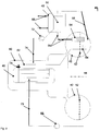
- Fig. 1 shows a first exemplary cooling module 10 in a sectional view.
- an evaporation chamber 12 is provided in its interior.
- the riser is indicated as rotationally symmetrical about a rotation axis 28, but any other cross-sectional shapes are conceivable, for example rectangular or not interleaved variants .
- a connection 22 for a first pressure line or steam line is arranged, which leads to a capacitor, not shown.
- the cooling module protrudes in its lower region into the water of a condenser, not shown, whose maximum level is indicated by the dashed line with the reference numeral 14 and whose minimum level is indicated by the dashed line by the reference numeral 16. This ensures that condensation chamber water can always flow into the riser pipe, as indicated by the arrow with the reference numeral 24.
- the water level of the water located in the evaporation space is geodetically higher than the maximum and minimum level in the condensation chamber, as within which the cooling module 10 is to be assumed arranged. It is also to be assumed that the condensation chamber water has saturation temperature, that is, that the liquid and the overlying gaseous phase of the water are in saturation equilibrium and that the cooling module 10 has likewise assumed this temperature. Due to the geodetically higher arrangement of the evaporation chamber 12, the water therein is boiling under the mentioned boundary conditions.
- the boiling process also generates steam, which is then conducted through the connection 22 in the upper region of the evaporation space to a condenser, not shown, where the heat is released by condensation in an equally effective manner.
- a suitable material for a cooling module according to the invention is, for example, stainless steel, wherein a cooling module - depending on the design - for example, may have a height of, for example, 1 m to 2 m. This height difference is sufficient to cause boiling in the evaporation space 12 at saturation temperature conditions.
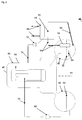
- Fig. 2 shows an exemplary boiling water reactor with Kondensationsschkühlsystem in a schematic view 40.
- a boiling water reactor 46 is disposed within a security or pressure vessel 60, which has, for example, a height of 10m.
- a ring-like condensation chamber 42 is provided in the form of a torus about this, arranged around a rotation axis 44, which is connected to the pressure vessel 60 via corresponding pressure-resistant pipe connections.
- the condensation chamber is filled up to a level 52 with condensation chamber water.
- a drain line 62 closable by means of a drain valve 76 leads into the condensation chamber 42 and flows below the fill level 52 into a distributor 64.
- the latter ensures a particularly good penetration of the condensation chamber water from steam flowing through the drain line 62.
- Steam is then introduced from the boiling water reactor 46 into the drain line 62 when it is created during the reactor cooling and with it too high a pressure. This steam leads to condensation in the condensation chamber to a heating of the condensation chamber water therein.
- a cooling module 54 Vertically disposed within the condensation chamber 42 and into the condensation chamber water projecting is a cooling module 54. This has an evaporator chamber and a riser down pipe, wherein water rises through the riser into the evaporator chamber, there boiling with the release of steam, is cooled and by the Downpipe falls back down again. Thus, a cooling of the condensation chamber water is effected. It is thus formed another natural cooling circuit.
- the resulting vapor is conducted from the evaporator chamber via a first pressure line 56 to a heat exchanger 48, which in particular has a capacitor 50.
- a heat exchanger 48 which in particular has a capacitor 50.
- the steam is transferred with the release of heat in the liquid water state and led back from the condenser 50 via a steadily falling second pressure line 58 back into the condensation chamber 42, which is done solely by gravity.
- the heat exchanger 48 is in turn connected via corresponding inlet and outlet lines directly or indirectly with a heat sink for heat dissipation to the environment, such as a cooling tower.
- a vacuum pump 72 having a return line 74 acting on the cooling circuit is provided to evacuate the passively operating condensation chamber cooling system during normal plant operation. This ensures that only liquid or gaseous water is within the pipe system or cooling circuit. During the request, the vacuum pump 72 remains in operation to prevent accumulation of non-condensable gases.
- condensation water can be back into the boiling water reactor 46, so that its water inventory is maintained despite the discharge of steam into the condensation chamber 42.
Description
Die Erfindung betrifft eine Kondensationskammer mit Kondensationskammerkühlsystem, umfassend eine Kondensationskammer für einen Siedewasserreaktor und wenigstens einen außerhalb der Kondensationskammer angeordneten Wärmetauscher.The invention relates to a condensation chamber with the condensation chamber cooling system comprising a condensation chamber for a boiling water reactor and at least one is arranged outside the condensation chamber heat exchanger.
Es ist allgemein bekannt, dass Leichtwasserreaktoren zur Stromerzeugung genutzt werden. Hierbei erzeugt nuklearer Brennstoff, beispielsweise in Form von Uranbrennstäben, in einem Reaktorkern in einem nuklearen Spalt- und Zerfallsprozess Wärme. In jedem Fall ist durch eine Wärmeabfuhr aus dem Reaktorkern dafür zu sorgen, dass dieser innerhalb eines unkritischen Temperaturbereiches bleibt. Bei Leichtwasserreaktoren (Druck- und Siedewasserreaktoren) ist der Reaktorkern innerhalb eines Druckbeziehungsweise Sicherheitsbehälters angeordnet. Dieser bildet bei Druckwasserreaktoren mit einem Dampferzeuger und den Zu- bzw. Ableitungen ein geschlossenes System zum Umlauf von Kühlmittel, das eigentliche Kernreaktorkühlsystem. Zur Abfuhr der durch den Kontakt des Kühlmittels mit den Brennelementen übertragenden Wärme dienen bei einem Druckwasserreaktor im normalen Betrieb der Dampferzeuger und die nachgeschaltete Dampfturbine mit ihrem Kondensator. Bei Siedewasserreaktoren entfallen die Dampferzeuger, d. h. der Dampf aus dem Reaktor wird zum Antrieb der Wasserdampfturbinen direkt genutzt wobei so die Wärme des Kühlmittels abgegeben wird. Eine typische Reaktorleistung beträgt beispielsweise 1,4GW.It is well known that light water reactors are used to generate electricity. Here, nuclear fuel, for example in the form of uranium fuel rods, generates heat in a reactor core in a nuclear fission and decay process. In any case, heat removal from the reactor core must ensure that it remains within a non-critical temperature range. In light water reactors (pressurized and boiling water reactors), the reactor core is located within a pressure tank or containment vessel. This forms in pressurized water reactors with a steam generator and the supply and discharge lines a closed system for circulation of coolant, the actual nuclear reactor cooling system. To dissipate the transferred by the contact of the coolant with the fuel heat used in a pressurized water reactor in normal operation of the steam generator and the downstream steam turbine with its condenser. In boiling water reactors, the steam generators are eliminated, ie the steam from the reactor is used directly to drive the steam turbines so that the heat of the coolant is discharged. For example, a typical reactor power is 1.4GW.
Aber auch wenn ein Leichtwasserreaktor, beispielsweise zu Wartungszwecken, komplett heruntergefahren worden ist, erzeugt er für einen längeren Zeitraum eine Restwärme, die Nachzerfallswärme. Wird diese nicht zuverlässig abgeführt, kann es zu einer unerlaubten Temperaturerhöhung des Reaktorkerns mit möglichen Brennelementeschäden bis hin zur Kernschmelze kommen.But even if a light water reactor, for example, for maintenance purposes, has been completely shut down, it generates a residual heat for a longer period, the Nachzerfallswärme. If this is not reliably dissipated, it may lead to an unauthorized increase in temperature of the reactor core with possible fuel damage to the meltdown.
Ist bei einem Siedewasserreaktor der Reaktorkern mit Wasser überdeckt, kann von einer ausreichenden Kühlung ausgegangen werden. Bei Siedewasserreaktoren wird die nach einer Abschaltung entstehende Nachzerfallswärme durch Sieden des die Brennelemente umgebenden Wassers abgeführt. Durch Verdampfen des Wassers erfolgt ein der jeweiligen Verdampfungsenergie entsprechender Kühleffekt der Brennelemente. Der so entstehende Dampf wird über Sicherheitsventile in eine Wasservorlage außerhalb des Druck- beziehungsweise Sicherheitsbehälters in eine sogenannte Kondensationskammer abgeblasen und dort kondensiert. Das durch Abblasen Dampfes in die Kondensationskammer verlorene Wasserinventar des Druckbehälters wird typischerweise durch aktive Einspeisesysteme aus der Kondensationskammer zurück in den Druckbehälter geführt.If the reactor core is covered with water in a boiling water reactor, sufficient cooling can be assumed. In boiling water reactors, the after-decay heat generated after a shutdown is removed by boiling the water surrounding the fuel elements. By evaporating the water, a cooling effect of the fuel elements corresponding to the respective evaporation energy takes place. The resulting steam is blown off via safety valves in a water reservoir outside the pressure or safety container in a so-called condensation chamber and condensed there. The lost by blowing off steam into the condensation chamber water inventory of the pressure vessel is typically performed by active feed systems from the condensation chamber back into the pressure vessel.
Beim Kondensieren, also beim Übergang des gasförmigen Dampfes in seinen flüssigen Zustand, erfolgt eine jeweilige Energieabgabe, welche zu einer Erhitzung des in der Kondensationskammer befindlichen Wassers führt. Daher sind entsprechend dem Stand der Technik aktive Not- und Nachkühlsysteme vorgesehen, mittels welcher über entsprechende Wärmetauscher und Wärmekreisläufe eine Kühlung der Kondensationskammer beziehungsweise der in dieser befindlichen Wasservorlage und eine Wärmeübertragung an eine externe Wärmesenke, beispielsweise einen Kühlturm, erfolgt.When condensing, ie the transition of the gaseous vapor into its liquid state, there is a respective energy output, which leads to a heating of the water located in the condensation chamber. Therefore, according to the state of the art, active emergency and aftercooling systems are provided, by means of which a cooling of the condensation chamber or of the water reservoir present therein and heat transfer to an external heat sink, for example a cooling tower, takes place via corresponding heat exchangers and heat circuits.
Das PatentdokumentThe patent document
Das PatentdokumentThe
Das PatentdokumentThe patent document
Als nachteilig erweist es sich hierbei, dass derartige Kühlsysteme zur Abführung der in die Kondensationskammer eingetragenen Kondensationswärme aktiver Natur sind, also aktive Komponenten wie beispielsweise Umlaufpumpen für das Kühlmedium Wasser erfordern. Trotz höchster Sicherheitsmaßnahmen und redundanter Auslegung der jeweiligen Kühlsysteme kann nicht vollständig ausgeschlossen werden, den, dass ein aktiver Kühlkreislauf nach Ausfall beispielsweise seiner Umlaufpumpe in einem Störfall nicht zur Verfügung steht.It proves to be disadvantageous in this case that such cooling systems for discharging the condensation heat introduced into the condensation chamber are of an active nature, that is to say that active components such as circulation pumps for the cooling medium require water. Despite the highest safety measures and redundant design of the respective cooling systems can not be completely ruled out that an active cooling circuit after failure, for example, his circulation pump in an accident is not available.
Ausgehend von diesem Stand der Technik ist es Aufgabe der Erfindung ein Kondensationskammerkühlsystem anzugeben, welches aktive Komponenten und insbesondere Umlaufpumpen möglichst vermeidet.Based on this prior art, it is an object of the invention to provide a condensation chamber cooling system which avoids active components and in particular circulation pumps as possible.
Diese Aufgabe wird gelöst durch ein Kondensationskammerkühlsystem der eingangs genannten Art. Dieses ist dadurch gekennzeichnet, dass in der Kondensationskammer ein längliches Kühlmodul vorgesehen ist, mit einem in seinem oberen Bereich befindlichen Verdampfungsraum, wobei das Kühlmodul derart in der Kondensationskammer angeordnet ist, dass der Verdampfungsraum oberhalb eines Höchstfüllstandniveaus einer Wasservorlage in der Kondensationskammer befindlich ist. Fernerhin umfasst das erfindungsgemäße Kondensationskammerkühlsystem wenigstens ein Steig- und ein Fallrohr, welche mit ihren jeweiligen oberen Enden in den Verdampfungsraum münden und mit ihren jeweiligen unteren Enden in der Kondensationskammer unterhalb eines Mindestfüllstandsniveaus der Wasservorlage, wobei eine erste Druckleitung vom Verdampfungsraum zum Wärmetauscher vorgesehen ist und von dort eine zweite Druckleitung, welche in der Kondensationskammer vorzugsweise unterhalb des Mindestfüllstandsniveaus mündet, so dass durch die Kondensationskammer, die Druckleitungen, das Kühlmodul und den Wärmetauscher ein passiver geschlossener Kühlkreislauf gebildet ist.This object is achieved by a condensation chamber cooling system of the aforementioned type. This is characterized in that an elongate cooling module is provided in the condensation chamber, with an evaporation space located in its upper region, the cooling module being arranged in the condensation chamber such that the evaporation space above a maximum level of a water reservoir is located in the condensation chamber. Furthermore, the condensation chamber cooling system according to the invention comprises at least one riser and one downcomer, which open with their respective upper ends in the evaporation space and with their respective lower ends in the condensation chamber below a minimum level of the water mask, wherein a first pressure line from the evaporation space to the heat exchanger is provided and there a second pressure line, which opens in the condensation chamber preferably below the minimum level, so that a passive closed cooling circuit is formed by the condensation chamber, the pressure lines, the cooling module and the heat exchanger.
Die Grundidee der Erfindung besteht darin, ein Kondensationskammerkühlsystem mit Naturumlauf des Kühlmittels beziehungsweise Wassers bereitzustellen, somit eine aktive Umlaufpumpe zu vermeiden und damit die Ausfallwahrscheinlichkeit des Kühlsystems zu reduzieren.The basic idea of the invention is to provide a condensation chamber cooling system with natural circulation of the coolant or water, thus avoiding an active circulation pump and thus reducing the probability of failure of the cooling system.
Bei Ausfall der aktiven Nachwärmeabfuhrsysteme im Anforderungsfall heizt sich das Kondensationskammerwasser beziehungsweise die Wasservorlage auf und der Druck innerhalb des Druck- beziehungsweise Sicherheitsbehälters steigt an. Damit steigt auch der Druck in der damit verbundenen Kondensationskammer an. Die flüssige Phase des Wassers in der Kondensationskammer und die darüber befindliche gasförmige Phase befinden sich nach einer gewissen Zeit im Sättigungsgleichgewicht, das heißt, das Kondensationskammerwasser weist eine Sättigungstemperatur entsprechend dem Sicherheitsbehälterinnendruck auf.In case of failure of the active Nachwärmeabfuhrsysteme in the request case heats the condensation chamber water or the water mask on and the pressure within the pressure or safety container increases. Thus, the pressure in the associated condensation chamber increases. The liquid phase of the water in the condensation chamber and the gaseous phase above it are in saturation equilibrium after a certain time, that is, the condensation chamber water has a saturation temperature corresponding to the safety tank internal pressure.
Das Steig-Fallrohr befindet sich in vorzugsweise etwa senkrechter Anordnung komplett innerhalb der Kondensationskammer und ragt mit seinem unteren Ende in das flüssige Kondensationskammerwasser. Das flüssige Wasser innerhalb des Steig-Fallrohres erwärmt sich ebenfalls auf die Temperatur innerhalb der Kondensationskammer, welche beispielsweise als Torus- ähnlicher Ring um den unteren Bereich des Sicherheitsbehälters ausgestaltet sein kann. Der Wasserspiegel innerhalb des Steig-Fallrohres ist jedoch geodätisch höher als der Wasserspiegel beziehungsweise das Füllstandsniveau der Kondensationskammer.The riser downpipe is located in preferably approximately vertical arrangement completely within the condensation chamber and protrudes with its lower end into the liquid condensation chamber water. The liquid water within the riser down pipe also heats up to the temperature within the condensation chamber, which may be configured, for example, as a torus-like ring around the lower portion of the containment. However, the water level within the riser downpipe is geodetically higher than the water level or the level of the condensing chamber.
Aufgrund des geodätischen Höhenunterschiedes des Wasserspiegels in der Kondensationskammer und des Wasserspiegels im Steig-Fallrohr beziehungsweise im Verdampfungsraum, in welchen die Rohre mit ihren jeweiligen oberen Enden münden, ist der statische Druck im Verdampfungsraum bei einem Höhenunterschied von beispielsweise 2m entsprechend geringer. Befindet sich das Kondensationskammerwasser wie zuvor erläutert auf Sättigungstemperatur, siedet das Wasser in dem oberhalb des Wasserspiegels der Kondensationskammer befindlichen Verdampfungsraum beziehungsweise den entsprechenden Rohrabschnitten aufgrund des dort herrschenden geringeren statischen Drucks.Due to the geodetic difference in height of the water level in the condensation chamber and the water level in the riser down pipe or in the evaporation space in which open the tubes with their respective upper ends, the static pressure in the evaporation chamber at a height difference of for example 2m is correspondingly lower. If the condensation chamber water is at saturation temperature, as explained above, the water will boil in the evaporation space located above the water level of the condensation chamber or the corresponding pipe sections due to the lower static pressure prevailing there.
Der Siedevorgang führt zu einer Kühlung des in dem Verdampfungsraum befindlichen Wassers einerseits und einer Dampfentstehung andererseits. Das Steig-Fallrohr ist so ausgestaltet, dass Wasser auf Sättigungstemperatur über das Steigrohr in den Verdampfungsraum geführt wird und dort durch den Siedevorgang unter Dampfbildung gekühlt wird. Das gekühlte Wasser, welches dann eine entsprechend höhere Dichte aufweist als das Wasser auf Sättigungstemperatur, wird dann wieder über das Fallrohr der Wasservorlage innerhalb der Kondensationskammer zugeführt. Durch diesen Dichteunterschied ist ein natürlicher Umlauf des Wassers durch das Kühlmodul ermöglicht, welcher in vorteilhafter Weise keinerlei aktive Umlaufpumpe oder dergleichen erfordert.The boiling process leads to a cooling of the water located in the evaporation chamber on the one hand and a vapor formation on the other. The riser downpipe is designed so that water is passed to saturation temperature via the riser pipe in the evaporation space and is cooled there by the boiling process with formation of steam. The cooled water, which then has a correspondingly higher density than the water to saturation temperature, is then returned via the downcomer to the water reservoir within the condensation chamber. By this difference in density, a natural circulation of the water is made possible by the cooling module, which advantageously requires no active circulation pump or the like.
Um ein unmittelbares Vermischen von in das Steigrohr eintretendem Wasser und aus dem Fallrohr austretendem gekühlten Wasser zu vermeiden, sind deren jeweilige untere Mündungen vorzugsweise versetzt zueinander angeordnet.In order to avoid a direct mixing of water entering the riser and cooled water leaving the downpipe, their respective lower orifices are preferably offset relative to one another.
Der in dem Verdampfungsraum entstehende Dampf wird von dort durch die erste Druckleitung, einer Dampfleitung, zum vorzugsweise einen Kondensator umfassenden Wärmetauscher geleitet, wo der Dampf durch Kondensation Wärme an den Wärmetauscher abgibt. Dieser führt die Wärme dann direkt oder indirekt an eine externe Wärmesenke ab, beispielsweise an einen Kühlturm. So kann der Wärmetauscher aber auch über ein Wasserreservoir verfügen, welches die Kondensationswärme aufnimmt und mittels eines weiteren Wasserumlaufs ableitet. Das beim Kondensieren entstehende Kondensat wird über die zweite Druckleitung, einer Kondensatleitung, vom Kondensator zurück in die Kondensationskammer geleitet. Idealerweise ist der Wärmetauscher auf einer derartigen geodätischen Höhe oberhalb der Kondensationskammer angeordnet, dass das Kondensat über die vorzugsweise mit einem steten Gefälle ausgestalteten Kondensatleitung alleine schwerkraftbedingt in die Kondensationskammer zurückfließt. Somit ist auch für diesen Kühlmittelkreislauf in vorteilhafter Weise kein aktives Pumpelement notwendig.The resulting vapor in the evaporation chamber is passed from there through the first pressure line, a steam line, preferably to a condenser comprising a heat exchanger, where the steam gives off by condensation heat to the heat exchanger. This then dissipates the heat directly or indirectly to an external heat sink, for example to a cooling tower. However, the heat exchanger can also have a water reservoir which absorbs the condensation heat and dissipates it by means of a further water circulation. The condensate formed during condensation is conducted via the second pressure line, a condensate line, from the condenser back into the condensation chamber. Ideally, the heat exchanger is arranged on such a geodetic height above the condensation chamber, that the condensate alone flows back into the condensation chamber via the condensate line, which is preferably designed with a constant gradient. Thus, no active pumping element is necessary for this coolant circuit in an advantageous manner.
Auf diese Weise können auch bei vergleichsweise niedrigen Wassertemperaturen, beispielsweise 120°C oder 140°C, hohe Wärmeströme realisiert werden, weil das zu kühlende Medium, nämlich das in der Kondensationskammer befindliche Wasser, direkt auch als Kühlmittel für den Kühlkreislauf verwendet wird. Damit entfallen in vorteilhafter Weise ein sonst notwendiger Wärmetauschvorgang zwischen Kühlmittel und zu kühlendem Medium und die dafür erforderlichen Wärmetauscher.In this way, even at comparatively low water temperatures, for example 120 ° C or 140 ° C, high heat flows can be realized because the medium to be cooled, namely the water in the condensation chamber is used directly as a coolant for the cooling circuit. This eliminates advantageously an otherwise necessary heat exchange process between the coolant and the medium to be cooled and the necessary heat exchanger.
Entsprechend einer bevorzugten Ausgestaltung des erfindungsgemäßen Kondensationskammerkühlsystems ist das Fallrohr in das Steigrohr verschachtelt, so dass ein äußeres Steigrohr und ein darin verlaufendes inneres Fallrohr gebildet sind. Dies erweist sich als fertigungstechnisch als besonders günstig und ermöglicht zudem eine hohe mechanische Stabilität des erfindungsgemäßen Kühlmoduls.According to a preferred embodiment of the condensation chamber cooling system according to the invention, the drop tube is nested in the riser, so that an outer riser and an inner downpipe extending therein are formed. This proves to be particularly favorable as a manufacturing technology and also allows a high mechanical stability of the cooling module according to the invention.
Gemäß einer weiteren Ausgestaltung des erfindungsgemäßen Kondensationskammerkühlsystems umfasst dessen Wärmetauscher einen Verdampfungskondensator.According to a further embodiment of the condensation chamber cooling system according to the invention, the heat exchanger comprises an evaporation condenser.
Dieser ermöglicht wie zuvor erläutert aufgrund der abgegebenen Kondensationswärme einen sehr effektiven Wärmetausch.This allows as previously explained due to the heat of condensation given off a very effective heat exchange.
Einer weiteren Ausgestaltungsvariante des Kondensationskammerkühlsystems entsprechend mündet eine Abblasleitung unterhalb des Mindestfüllstandsniveaus in der Kondensationskammer. Diese Leitung ist dafür vorgesehen, aus einem zugehörigen Siedewasserreaktor über ein Ablassventil abgelassenen Dampf in die Wasservorlage der Kondensationskammer einzuführen. Hierdurch wird das Kondensationskammerwasser entsprechend erhitzt. Vorzugsweise ist diese Leitung an ihrem Ende verästelt um so eine verbesserte Durchdringung des Wassers mit dem Dampf zu ermöglichen. Hierdurch wird die Kondensation des Dampfes und damit der auch die Effektivität des Kondensationskammerkühlsystems verbessert.According to a further embodiment variant of the condensation chamber cooling system, a discharge line opens below the minimum filling level in the condensation chamber. This line is intended to introduce vapor released from an associated boiling water reactor via a drain valve into the water reservoir of the condensation chamber. As a result, the condensation chamber water is heated accordingly. Preferably, this line is branched at its end so as to allow an improved penetration of the water with the steam. As a result, the condensation of the vapor and thus also the effectiveness of the condensation chamber cooling system is improved.
Entsprechend einer bevorzugten Variante des erfindungsgemäßen Kondensationskammerkühlsystems ist eine auf den Kühlkreislauf wirkende Vakuumpumpe vorgesehen. Während des normalen Anlagenbetriebes wird damit das passiv arbeitende Kondensationskammerkühlsystems evakuiert. Dadurch ist gewährleistet, dass sich ausschließlich flüssiges oder gasförmiges Wasser innerhalb des Rohrsystems beziehungsweise Kühlkreislaufes befindet. Während der Anforderung im Abschaltungsfall bleibt die Vakuumpumpe in Betrieb, um eine Ansammlung nichtkondensierbarer Gase zu vermeiden.According to a preferred variant of the condensation chamber cooling system according to the invention, a vacuum pump acting on the cooling circuit is provided. During normal plant operation, the passively operating condensation chamber cooling system is thus evacuated. This ensures that only liquid or gaseous water is within the pipe system or cooling circuit. During the shutdown request, the vacuum pump remains in operation to prevent accumulation of non-condensable gases.
Gemäß einer besonders bevorzugten Ausgestaltung des erfindungsgemäßen Kondensationskammerkühlsystems ist der wenigstens eine Wärmetauscher geodätisch oberhalb der Kondensationskammer angeordnet. Dies ermöglicht bei entsprechender stetig fallend ausgeführter Kondensatleitung eine rein schwerkraftgetriebene Rückführung des Kondensats in die Kondensationskammer, so dass keine Pumpmittel erforderlich sind.According to a particularly preferred embodiment of the condensation chamber cooling system according to the invention, the at least one heat exchanger is arranged geodetically above the condensation chamber. This allows for a correspondingly falling falling condensate line a purely gravity-driven return of the condensate in the condensation chamber, so that no pumping means are required.
Vorzugsweise entspricht das Mindestfüllstandsniveau der Kondensationskammer zumindest annähernd deren Höchstfüllstandsniveau. Die Kühleigenschaften des Kondensationskammerkühlsystem werden dadurch konstant gehalten. Ein derartiges annähernd gleiches Füllstandsniveau wird durch entsprechende geregelte Rückführung von Kondensationskammerwasser in den Reaktor erreicht.The minimum filling level of the condensation chamber preferably corresponds at least approximately to its maximum filling level. The cooling properties of the condensation chamber cooling system are thereby kept constant. Such approximately the same level level is achieved by appropriate controlled recycling of Kondensationskammerwasser in the reactor.
Eine besonders bevorzugte Variante des erfindungsgemäßen Kondensationskammerkühlsystem ist dadurch gekennzeichnet, dass wenigstens ein zusätzlicher aktiver Kühlkreislauf zur Abführung von Abwärme aus der Kondensationskammer vorgesehen ist. Somit ist ein Gesamtkühlsystem für die Kondensationskammer geschaffen, welches diversitär ist, also auf verschieden arbeitenden Kühlsystemen basiert. Der gleichzeitige Ausfall von diversitär arbeitenden Kühlsystemen ist unwahrscheinlicher als der gleichzeitige Ausfall von gleichartig arbeitenden Kühlsystemen. Somit ist in vorteilhafter Weise die Sicherheit eines derartigen Gesamtkühlsystems weiter gesteigert. Idealerweise ist zumindest das aktive Kühlsystem zudem noch redundant ausgelegt, also aus mehreren gegebenenfalls gleichartigen und parallel arbeitenden Einzelsystemen, deren summarische Kühlleistung unterhalb der maximal zu erwartenden Kühlleistung liegt, so dass trotz eines eventuellen Ausfalls eines Systems eine sichere Kühlung gewährleistet ist. Die zusätzliche Verwendung eines zuvor beschriebenen passiven Systems steigert die Betriebssicherheit weiter, wobei dessen Einzelausfallwahrscheinlichkeit aufgrund des passiven Prinzips besonders niedrig ist.A particularly preferred variant of the condensation chamber cooling system according to the invention is characterized in that at least one additional active cooling circuit is provided for the removal of waste heat from the condensation chamber. Thus, a total cooling system for the condensation chamber is created, which is diverse, so based on different working cooling systems. The simultaneous failure of diversely operating cooling systems is less likely than the simultaneous failure of similar cooling systems. Thus, advantageously, the safety of such a total cooling system is further increased. Ideally, at least the active cooling system is also designed to be redundant, so from several possibly similar and parallel operating individual systems, the total cooling capacity is below the maximum expected cooling capacity, so that despite a possible failure of a system safe cooling is guaranteed. The additional use of a passive system described above further increases the reliability, the individual failure probability is particularly low due to the passive principle.
Erfindungsgemäß ist einer Ausgestaltungsvariante folgend ein Pumpsystem für die Rückführung von in der Kondensationskammer befindlichem Wasser in den zugehörigen Siedewasserreaktor vorgesehen. Dieses ist wie zuvor erwähnt zur Erhaltung des Wasserinventars des Siedewasserreaktors notwendig und kann auch als Teil des erfindungsgemäßen Kühlsystems angesehen werden.According to the invention, following a design variant, a pumping system for the return of water in the condensation chamber to the associated boiling water reactor is provided. This is necessary as mentioned above to maintain the water inventory of the boiling water reactor and may also be considered part of the refrigeration system of the present invention.
Der Wärmetauscher ist erfindungsgemäß dafür vorgesehen ist, Abwärme an die Umgebung abzuführen. Dies kann gegebenenfalls über das Zwischenschalten weiterer Kühlkreisläufe und Wärmetauscher erfolgen, wobei ein Kühlturm eine bevorzugte Wärmesenke für die abschließende Wärmeabgabe an die Umgebung darstellt.The heat exchanger according to the invention is intended to dissipate waste heat to the environment. This can optionally take place via the interposition of further cooling circuits and heat exchangers, wherein a cooling tower represents a preferred heat sink for the final heat release to the environment.
Weitere vorteilhafte Ausgestaltungsmöglichkeiten sind den weiteren abhängigen Ansprüchen zu entnehmen.Further advantageous embodiment possibilities can be found in the further dependent claims.
Anhand der in den Zeichnungen dargestellten Ausführungsbeispiele sollen die Erfindung, weitere Ausführungsformen und weitere Vorteile näher beschrieben werden.Reference to the embodiments illustrated in the drawings, the invention, further embodiments and other advantages will be described in detail.
Es zeigen
- Fig. 1
- ein erstes exemplarisches Kühlmodul und
- Fig. 2
- einen exemplarischen Siedewasserreaktor mit Kondensationskammerkühlsystem.
- Fig. 1
- a first exemplary cooling module and
- Fig. 2
- an exemplary boiling water reactor with condensation chamber cooling system.
Das Wasserstandsniveau des im Verdampfungsraum befindlichen Wassers ist geodätisch höher als das Höchst- und Mindestfüllstandsniveau in der Kondensationskammer, als innerhalb derer das Kühlmodul 10 angeordnet anzunehmen ist. Es ist ferner davon auszugehen, dass das Kondensationskammerwasser Sättigungstemperatur aufweist, das heißt, dass die flüssige und die darüber liegende gasförmige Phase des Wassers im Sättigungsgleichgewicht sind und dass das Kühlmodul 10 ebenfalls diese Temperatur angenommen hat. Aufgrund der geodätisch höheren Anordnung der Verdampfungsraum 12 siedet das darin befindliche Wasser unter den genannten Randbedingungen.The water level of the water located in the evaporation space is geodetically higher than the maximum and minimum level in the condensation chamber, as within which the cooling module 10 is to be assumed arranged. It is also to be assumed that the condensation chamber water has saturation temperature, that is, that the liquid and the overlying gaseous phase of the water are in saturation equilibrium and that the cooling module 10 has likewise assumed this temperature. Due to the geodetically higher arrangement of the
Dies hat einerseits den Effekt, dass das siedende Wasser gekühlt wird, also Wärme abgibt. Durch das Abkühlen des Wassers steigt dessen Dichte und es sinkt durch das Fallrohr 20 zurück unterhalb des Mindestfüllstandsniveaus, wie mit dem Pfeil 26 angedeutet, es ist also ein Naturumlauf des Wassers bewirkt. Damit ist eine sehr effektive Kühlung des Kondensationskammerwassers erreicht, weil dieses direkt als Kühlmittel verwendet wird, welches durch den Siedevorgang in sehr effektiver Weise Wärme abgibt.This has the effect on the one hand that the boiling water is cooled, ie gives off heat. As the water cools, its density increases and it falls through the
Durch den Siedevorgang wird andererseits auch Dampf erzeugt, welcher dann durch den Anschluss 22 im oberen Bereich der Verdampfungsraum zu einem nicht gezeigten Kondensator geführt wird, wo durch Kondensation in ebenso effektiver Weise die Wärme abgegeben wird.On the other hand, the boiling process also generates steam, which is then conducted through the
Ein geeignetes Material für ein erfindungsgemäßes Kühlmodul ist beispielsweise Edelstahl, wobei ein Kühlmodul - je nach Ausführung - beispielsweise eine Höhe von beispielsweise 1 m bis 2m aufweisen kann. Dieser Höhenunterschied ist ausreichend, um bei Sättigungstemperaturbedingungen ein Sieden in dem Verdampfungsraum 12 zu bewirken.A suitable material for a cooling module according to the invention is, for example, stainless steel, wherein a cooling module - depending on the design - for example, may have a height of, for example, 1 m to 2 m. This height difference is sufficient to cause boiling in the
Vom Siedewasserreaktor 46 führt eine mittels eines Ablassventils 76 verschließbare Ablassleitung 62 in die Kondensationskammer 42 und mündet dort unterhalb des Füllstandsniveaus 52 in eine Verteilvorrichtung 64. Letztere stellt eine besonders gute Durchdringung des Kondensationskammerwassers von durch die Ablassleitung 62 strömenden Dampf sicher. Dampf wird dann aus dem Siedewasserreaktor 46 in die Ablassleitung 62 eingeführt, wenn dieser bei der Reaktorkühlung entstanden ist und mit ihm ein zu hoher Druck. Dieser Dampf führt bei Kondensierung in der Kondensationskammer zu einer Erhitzung des darin befindlichen Kondensationskammerwassers.From the boiling
Senkrecht innerhalb der Kondensationskammer 42 und in das Kondensationskammerwasser ragend angeordnet ist ein Kühlmodul 54. Dieses weist eine Verdampferkammer und ein Steig-Fallrohr auf, wobei Wasser durch das Steigrohr in die Verdampferkammer aufsteigt, dort unter Abgabe von Dampf siedet, dadurch gekühlt wird und durch das Fallrohr wieder zurück nach unten fällt. Somit ist eine Kühlung des Kondensationskammerwassers bewirkt. Es ist somit ein weiterer natürlicher Kühlkreislauf gebildet.Vertically disposed within the
Der dabei entstehende Dampf wird aus der Verdampferkammer über eine erste Druckleitung 56 zu einem Wärmetauscher 48 geführt, welcher insbesondere einen Kondensator 50 aufweist. Hier wird der Dampf unter Abgabe von Wärme in den flüssigen Wasserzustand überführt und vom Kondensator 50 über eine stetig fallende zweite Druckleitung 58 wieder zurück in die Kondensationskammer 42 geführt, wobei dies ausschließlich schwerkraftbedingt erfolgt. Der Wärmetauscher 48 ist seinerseits über entsprechende Zu- und Abführleitungen direkt oder indirekt mit einer Wärmesenke zur Wärmeabgabe an die Umgebung verbunden, beispielsweise einem Kühlturm.The resulting vapor is conducted from the evaporator chamber via a
Eine auf den Kühlkreislauf wirkende Vakuumpumpe 72 mit einer Rückführleitung 74 ist dafür vorgesehen, während des normalen Anlagenbetriebes das passiv arbeitende Kondensationskammerkühlsystems zu evakuieren. Dadurch ist gewährleistet, dass sich ausschließlich flüssiges oder gasförmiges Wasser innerhalb des Rohrsystems beziehungsweise Kühlkreislaufes befindet. Während der Anforderung bleibt die Vakuumpumpe 72 in Betrieb, um eine Ansammlung nichtkondensierbarer Gase zu vermeiden.A
Mittels einer Einspeisepumpe 68 und einer Wasserrückführleitung 70 lässt sich Kondensationskammerwasser wieder zurück in den Siedewasserreaktor 46 führen, so dass dessen Wasserinventar trotz Ablassen von Dampf in die Kondensationskammer 42 erhalten bleibt.By means of a
- 1010
- erstes exemplarisches Kühlmodulfirst exemplary cooling module
- 1212
- VerdampfungsraumEvaporation space
- 1414
- HöchstfüllstandniveauMaximum filling level
- 1616
- MindestfüllstandsniveauMinimum filling level
- 1818
- Steigrohrriser
- 2020
- Fallrohrdownspout
- 2222
- Anschluss für erste DruckleitungConnection for first pressure line
- 2424
- aufsteigendes Wasserrising water
- 2626
- absteigendes gekühltes Wasserdescending cooled water
- 2828
- Rotationsachse KühlmodulRotary axis cooling module
- 4040
- exemplarischer Siedewasserreaktor mit KondensationskammerkühlsystemExemplary boiling water reactor with condensation chamber cooling system
- 4242
- Kondensationskammercondensation chamber
- 4444
- Rotationsachse von KondensationskammerRotation axis of condensation chamber
- 4646
- Siedewasserreaktorboiling water reactor
- 4848
- Wärmetauscherheat exchangers
- 5050
- VerdampfungskondensatorEvaporative condenser
- 5252
- Füllstandsniveaufilling level
- 5454
- zweites exemplarisches Kühlmodulsecond exemplary cooling module
- 5656
- erste Druckleitungfirst pressure line
- 5858
- zweite Druckleitungsecond pressure line
- 6060
- Sicherheits- Druckbehälter für Reaktor (Reaktorcontainment)Safety pressure vessel for reactor (reactor containment)
- 6262
- Ablassleitungdrain line
- 6464
- Verteilervorrichtung für AblassleitungDistributor device for drain line
- 6666
- Zu- Ableitung für WärmetauscherInlet for heat exchanger
- 6868
- Einspeisepumpefeed pump
- 7070
- WasserrückführleitungWater return line
- 7272
- Vakuumpumpevacuum pump
- 7474
- RückführleitungReturn line
- 7676
- Ablassventildrain valve
Claims (10)
- Condensation chamber having a condensation chamber cooling system, comprising• a condensation chamber (42) for a boiling water reactor (46) and• at least one heat exchanger (48) arranged outside the condensation chamber (42),characterized in that,• in the condensation chamber (42), an elongate cooling module (10, 54) is provided, comprising• in its upper region an evaporation space (12), the cooling module (10, 54) being arranged in the condensation chamber (42) in such a way that the evaporation space (12) is located above a maximum filling level (14) of the condensation chamber (42),• at least one riser pipe (18) and one downpipe (20) which issue with their respective upper ends into the evaporation space (12) and with their respective lower ends in the condensation chamber (42) below a minimum filling level (16),a first pressure line (56) from the evaporation space (12) to the heat exchanger (48) being provided and, from there, a second pressure line (58) which issues in the condensation chamber (42), so that the condensation chamber (42), the pressure lines (56, 58), the cooling module (10, 54) and the heat exchanger (48) form a passive closed cooling circuit.
- Condensation chamber having a condensation chamber cooling system according to Claim 1, characterized in that the downpipe (20) is nested into the riser pipe (18).
- Condensation chamber having a condensation chamber cooling system according to either one of Claims 1 and 2, characterized in that the heat exchanger (48) comprises an evaporation condenser (50).
- Condensation chamber having a condensation chamber cooling system according to one of the preceding claims, characterized in that a blow-off line (62) issues below the minimum filling level (16) in the condensation chamber (42).
- Condensation chamber having a condensation chamber cooling system according to one of the preceding claims, characterized in that a vacuum pump (72) acting upon the cooling circuit is provided.
- Condensation chamber having a condensation chamber cooling system according to one of the preceding claims, characterized in that the at least one heat exchanger (48) is arranged geodetically above the condensation chamber (42).
- Condensation chamber having a condensation chamber cooling system according to one of the preceding claims, characterized in that the minimum filling level (16) corresponds at least approximately to the maximum filling level (18).
- Condensation chamber having a condensation chamber cooling system according to one of the preceding claims, characterized in that an additional active cooling circuit is provided for the discharge of waste heat from the condensation chamber (42).
- Condensation chamber having a condensation chamber cooling system according to one of the preceding claims, characterized in that a pumping system (68, 70) is provided for the return of water located in the condensation chamber (42) into the associated boiling water reactor (46).
- Condensation chamber having a condensation chamber cooling system according to one of the preceding claims, characterized in that the heat exchanger (48) is provided for discharging waste heat into the surroundings.
Applications Claiming Priority (1)
| Application Number | Priority Date | Filing Date | Title |
|---|---|---|---|
| DE102011115177A DE102011115177B3 (en) | 2011-09-28 | 2011-09-28 | Condensation chamber cooling system for use in boiling water reactor that is utilized for generating electricity from uranium fuel, has passive closed cooling circuit formed by condensation chamber, pressure lines, module and exchanger |
Publications (3)
| Publication Number | Publication Date |
|---|---|
| EP2575141A2 EP2575141A2 (en) | 2013-04-03 |
| EP2575141A3 EP2575141A3 (en) | 2015-07-01 |
| EP2575141B1 true EP2575141B1 (en) | 2016-03-30 |
Family
ID=46509787
Family Applications (1)
| Application Number | Title | Priority Date | Filing Date |
|---|---|---|---|
| EP12006588.3A Not-in-force EP2575141B1 (en) | 2011-09-28 | 2012-09-20 | Condensation chamber cooling system |
Country Status (5)
| Country | Link |
|---|---|
| US (1) | US9194629B2 (en) |
| EP (1) | EP2575141B1 (en) |
| JP (1) | JP6022286B2 (en) |
| DE (1) | DE102011115177B3 (en) |
| ES (1) | ES2576288T3 (en) |
Cited By (1)
| Publication number | Priority date | Publication date | Assignee | Title |
|---|---|---|---|---|
| DE102017008253B3 (en) * | 2017-09-01 | 2018-12-06 | Westinghouse Electric Germany Gmbh | Containment cooling system |
Families Citing this family (6)
| Publication number | Priority date | Publication date | Assignee | Title |
|---|---|---|---|---|
| US9368241B2 (en) | 2012-06-29 | 2016-06-14 | Ge-Hitachi Nuclear Energy Americas Llc | System and method for processing and storing post-accident coolant |
| US9406407B2 (en) * | 2012-12-11 | 2016-08-02 | Ge-Hitachi Nuclear Energy Americas Llc | Radioactive capture system for severe accident containment of light water reactors (LWRS), and method thereof |
| JP5853054B2 (en) | 2013-06-19 | 2016-02-09 | コリア アトミック エナジー リサーチ インスティチュート | Reactor containment cooling system |
| KR101545085B1 (en) | 2013-06-19 | 2015-08-18 | 한국원자력연구원 | Ong-term cooling system of nuclear reactor containment |
| KR101669765B1 (en) * | 2015-07-24 | 2016-10-26 | 이창건 | Cooling media producing apparatus using steam generated in nuclear power plant and method for cooling thereof |
| CN111785399B (en) * | 2020-07-06 | 2023-06-20 | 武汉第二船舶设计研究所(中国船舶重工集团公司第七一九研究所) | System for be used for ocean nuclear power platform heat to derive |
Family Cites Families (18)
| Publication number | Priority date | Publication date | Assignee | Title |
|---|---|---|---|---|
| US3397113A (en) * | 1966-05-10 | 1968-08-13 | Chicago Bridge & Iron Co | Modular suppression tanks for nuclear containment structures |
| US3431168A (en) * | 1967-06-26 | 1969-03-04 | Gen Electric | Reactor cooling system |
| DE2932815A1 (en) * | 1979-08-13 | 1981-03-26 | Kraftwerk Union AG, 45473 Mülheim | Boiling water reactor - with condensation chamber separate outside safety shell and joined by gas-tight tube surrounded pipe |
| JPS63109394A (en) * | 1986-10-27 | 1988-05-14 | 株式会社東芝 | Reactor-container protective device |
| JPS63212892A (en) * | 1987-02-28 | 1988-09-05 | 株式会社日立製作所 | Portable type quencher type filter bend system |
| JPH01199192A (en) * | 1988-02-04 | 1989-08-10 | Nippon Atom Ind Group Co Ltd | Protection of containment vessel |
| US4998509A (en) * | 1989-05-11 | 1991-03-12 | General Electric Company | Passive heat removal from containment |
| US4986956A (en) * | 1989-11-27 | 1991-01-22 | Stone & Webster Engineering Corporation | Passive nuclear power plant containment system |
| DE69018644T2 (en) * | 1990-08-14 | 1995-09-07 | Moritaka Ishimaru | NUCLEAR POWER PLANT AND CONSTRUCTION METHOD THEREFOR. |
| JP2507694B2 (en) * | 1990-09-17 | 1996-06-12 | 株式会社日立製作所 | Nuclear reactor equipment |
| JPH04128693A (en) * | 1990-09-20 | 1992-04-30 | Hitachi Ltd | Reactor container |
| US5295168A (en) * | 1993-04-15 | 1994-03-15 | General Electric Company | Pressure suppression containment system |
| SE9401559L (en) * | 1993-05-07 | 1994-11-08 | Gen Electric | Passive mixer |
| SE508995C2 (en) * | 1997-03-07 | 1998-11-23 | Asea Atom Ab | A nuclear reactor plant |
| US6069930A (en) * | 1997-06-27 | 2000-05-30 | General Electric Company | Modified passive containment cooling system for a nuclear reactor |
| US8170173B2 (en) * | 2007-11-15 | 2012-05-01 | The State Of Oregon Acting By And Through The State Board Of Higher Education On Behalf Of Oregon State University | Passive emergency feedwater system |
| KR100966854B1 (en) * | 2009-01-14 | 2010-06-29 | 한국원자력연구원 | Fully passive decay heat removal system for sodium cooled fast reactor with a partially-immersed decay heat exchanger |
| DE102010035955A1 (en) * | 2010-08-31 | 2012-03-01 | Westinghouse Electric Germany Gmbh | Fuel element storage tank with cooling system |
-
2011
- 2011-09-28 DE DE102011115177A patent/DE102011115177B3/en not_active Expired - Fee Related
-
2012
- 2012-09-20 ES ES12006588.3T patent/ES2576288T3/en active Active
- 2012-09-20 EP EP12006588.3A patent/EP2575141B1/en not_active Not-in-force
- 2012-09-28 US US13/630,789 patent/US9194629B2/en not_active Expired - Fee Related
- 2012-09-28 JP JP2012216404A patent/JP6022286B2/en not_active Expired - Fee Related
Cited By (1)
| Publication number | Priority date | Publication date | Assignee | Title |
|---|---|---|---|---|
| DE102017008253B3 (en) * | 2017-09-01 | 2018-12-06 | Westinghouse Electric Germany Gmbh | Containment cooling system |
Also Published As
| Publication number | Publication date |
|---|---|
| US20130140005A1 (en) | 2013-06-06 |
| JP2013072879A (en) | 2013-04-22 |
| JP6022286B2 (en) | 2016-11-09 |
| ES2576288T3 (en) | 2016-07-06 |
| EP2575141A3 (en) | 2015-07-01 |
| DE102011115177B3 (en) | 2012-07-12 |
| US9194629B2 (en) | 2015-11-24 |
| EP2575141A2 (en) | 2013-04-03 |
Similar Documents
| Publication | Publication Date | Title |
|---|---|---|
| EP2575141B1 (en) | Condensation chamber cooling system | |
| EP2423925B1 (en) | Fuel element storage pool with cooling system | |
| DE1881622U (en) | DEVICE FOR STEAM GENERATION WITH AN ATOMIC REACTOR AS A HEAT SOURCE. | |
| WO2008061609A1 (en) | Nuclear engineering plant and method for operating a nuclear engineering plant | |
| DE3435255A1 (en) | CORE REACTOR SYSTEM WITH A SMALL HT REACTOR WITH SPHERICAL FUEL ELEMENTS | |
| DE102008013933A1 (en) | Method and device for separating a neutron absorber from a coolant of a cooling circuit | |
| EP1053550B1 (en) | Pressure accumulator and method for providing a pressurized fluid | |
| EP0598787B1 (en) | Pressurized-water reactor residual-heat extraction system using the secondary cooling circuit | |
| WO2018011363A1 (en) | High-temperature radiation receiver system | |
| DE2554180A1 (en) | NUCLEAR REACTOR PLANT | |
| DE102017008253B3 (en) | Containment cooling system | |
| DE102012213489A1 (en) | Heat removal system for a nuclear installation | |
| DE102012007210B4 (en) | Method and device for the thermal storage of electrical energy | |
| DE1295720B (en) | Boiling water nuclear reactor | |
| EP3984046B1 (en) | Reactor pressure vessel cooling system | |
| EP2308576B1 (en) | Vaporiser | |
| EP0734028A1 (en) | Nuclear reactor containment structure | |
| DE3701604C2 (en) | ||
| EP1089294B1 (en) | Apparatus for pressure relief and passive introduction of coolant in a pressure vessel | |
| DE1639239A1 (en) | Nuclear power plant | |
| EP1777709B1 (en) | Method for controlling the pressure of the coolant in the primary cooling system of a nuclear reactor plant and nuclear reactor plant for implementing the same | |
| EP4089690B1 (en) | Security container cooling system | |
| DE3814691C2 (en) | ||
| DE2732774A1 (en) | High temp. gas cooled reactor with top reflector cooling - by secondary gas flow driven by own power source | |
| DE102013222272A1 (en) | Pressure relief system for a nuclear power plant and associated method |
Legal Events
| Date | Code | Title | Description |
|---|---|---|---|
| PUAI | Public reference made under article 153(3) epc to a published international application that has entered the european phase |
Free format text: ORIGINAL CODE: 0009012 |
|
| AK | Designated contracting states |
Kind code of ref document: A2 Designated state(s): AL AT BE BG CH CY CZ DE DK EE ES FI FR GB GR HR HU IE IS IT LI LT LU LV MC MK MT NL NO PL PT RO RS SE SI SK SM TR |
|
| AX | Request for extension of the european patent |
Extension state: BA ME |
|
| PUAL | Search report despatched |
Free format text: ORIGINAL CODE: 0009013 |
|
| AK | Designated contracting states |
Kind code of ref document: A3 Designated state(s): AL AT BE BG CH CY CZ DE DK EE ES FI FR GB GR HR HU IE IS IT LI LT LU LV MC MK MT NL NO PL PT RO RS SE SI SK SM TR |
|
| AX | Request for extension of the european patent |
Extension state: BA ME |
|
| RIC1 | Information provided on ipc code assigned before grant |
Ipc: G21C 15/26 20060101ALI20150528BHEP Ipc: G21C 15/18 20060101ALI20150528BHEP Ipc: G21D 3/04 20060101ALI20150528BHEP Ipc: G21D 1/02 20060101ALI20150528BHEP Ipc: G21C 19/28 20060101ALI20150528BHEP Ipc: G21C 15/243 20060101ALI20150528BHEP Ipc: G21C 9/012 20060101AFI20150528BHEP |
|
| 17P | Request for examination filed |
Effective date: 20150804 |
|
| GRAP | Despatch of communication of intention to grant a patent |
Free format text: ORIGINAL CODE: EPIDOSNIGR1 |
|
| INTG | Intention to grant announced |
Effective date: 20151023 |
|
| GRAS | Grant fee paid |
Free format text: ORIGINAL CODE: EPIDOSNIGR3 |
|
| GRAA | (expected) grant |
Free format text: ORIGINAL CODE: 0009210 |
|
| AK | Designated contracting states |
Kind code of ref document: B1 Designated state(s): AL AT BE BG CH CY CZ DE DK EE ES FI FR GB GR HR HU IE IS IT LI LT LU LV MC MK MT NL NO PL PT RO RS SE SI SK SM TR |
|
| REG | Reference to a national code |
Ref country code: GB Ref legal event code: FG4D Free format text: NOT ENGLISH |
|
| REG | Reference to a national code |
Ref country code: CH Ref legal event code: EP |
|
| REG | Reference to a national code |
Ref country code: AT Ref legal event code: REF Ref document number: 786132 Country of ref document: AT Kind code of ref document: T Effective date: 20160415 |
|
| REG | Reference to a national code |
Ref country code: IE Ref legal event code: FG4D Free format text: LANGUAGE OF EP DOCUMENT: GERMAN |
|
| REG | Reference to a national code |
Ref country code: DE Ref legal event code: R096 Ref document number: 502012006478 Country of ref document: DE |
|
| REG | Reference to a national code |
Ref country code: ES Ref legal event code: FG2A Ref document number: 2576288 Country of ref document: ES Kind code of ref document: T3 Effective date: 20160706 |
|
| REG | Reference to a national code |
Ref country code: LT Ref legal event code: MG4D |
|
| REG | Reference to a national code |
Ref country code: SE Ref legal event code: TRGR |
|
| PG25 | Lapsed in a contracting state [announced via postgrant information from national office to epo] |
Ref country code: HR Free format text: LAPSE BECAUSE OF FAILURE TO SUBMIT A TRANSLATION OF THE DESCRIPTION OR TO PAY THE FEE WITHIN THE PRESCRIBED TIME-LIMIT Effective date: 20160330 Ref country code: GR Free format text: LAPSE BECAUSE OF FAILURE TO SUBMIT A TRANSLATION OF THE DESCRIPTION OR TO PAY THE FEE WITHIN THE PRESCRIBED TIME-LIMIT Effective date: 20160701 Ref country code: NO Free format text: LAPSE BECAUSE OF FAILURE TO SUBMIT A TRANSLATION OF THE DESCRIPTION OR TO PAY THE FEE WITHIN THE PRESCRIBED TIME-LIMIT Effective date: 20160630 |
|
| REG | Reference to a national code |
Ref country code: NL Ref legal event code: MP Effective date: 20160330 |
|
| PG25 | Lapsed in a contracting state [announced via postgrant information from national office to epo] |
Ref country code: LV Free format text: LAPSE BECAUSE OF FAILURE TO SUBMIT A TRANSLATION OF THE DESCRIPTION OR TO PAY THE FEE WITHIN THE PRESCRIBED TIME-LIMIT Effective date: 20160330 Ref country code: LT Free format text: LAPSE BECAUSE OF FAILURE TO SUBMIT A TRANSLATION OF THE DESCRIPTION OR TO PAY THE FEE WITHIN THE PRESCRIBED TIME-LIMIT Effective date: 20160330 Ref country code: RS Free format text: LAPSE BECAUSE OF FAILURE TO SUBMIT A TRANSLATION OF THE DESCRIPTION OR TO PAY THE FEE WITHIN THE PRESCRIBED TIME-LIMIT Effective date: 20160330 |
|
| PG25 | Lapsed in a contracting state [announced via postgrant information from national office to epo] |
Ref country code: NL Free format text: LAPSE BECAUSE OF FAILURE TO SUBMIT A TRANSLATION OF THE DESCRIPTION OR TO PAY THE FEE WITHIN THE PRESCRIBED TIME-LIMIT Effective date: 20160330 |
|
| PG25 | Lapsed in a contracting state [announced via postgrant information from national office to epo] |
Ref country code: IS Free format text: LAPSE BECAUSE OF FAILURE TO SUBMIT A TRANSLATION OF THE DESCRIPTION OR TO PAY THE FEE WITHIN THE PRESCRIBED TIME-LIMIT Effective date: 20160730 Ref country code: PL Free format text: LAPSE BECAUSE OF FAILURE TO SUBMIT A TRANSLATION OF THE DESCRIPTION OR TO PAY THE FEE WITHIN THE PRESCRIBED TIME-LIMIT Effective date: 20160330 Ref country code: EE Free format text: LAPSE BECAUSE OF FAILURE TO SUBMIT A TRANSLATION OF THE DESCRIPTION OR TO PAY THE FEE WITHIN THE PRESCRIBED TIME-LIMIT Effective date: 20160330 |
|
| PG25 | Lapsed in a contracting state [announced via postgrant information from national office to epo] |
Ref country code: SK Free format text: LAPSE BECAUSE OF FAILURE TO SUBMIT A TRANSLATION OF THE DESCRIPTION OR TO PAY THE FEE WITHIN THE PRESCRIBED TIME-LIMIT Effective date: 20160330 Ref country code: PT Free format text: LAPSE BECAUSE OF FAILURE TO SUBMIT A TRANSLATION OF THE DESCRIPTION OR TO PAY THE FEE WITHIN THE PRESCRIBED TIME-LIMIT Effective date: 20160801 Ref country code: SM Free format text: LAPSE BECAUSE OF FAILURE TO SUBMIT A TRANSLATION OF THE DESCRIPTION OR TO PAY THE FEE WITHIN THE PRESCRIBED TIME-LIMIT Effective date: 20160330 Ref country code: CZ Free format text: LAPSE BECAUSE OF FAILURE TO SUBMIT A TRANSLATION OF THE DESCRIPTION OR TO PAY THE FEE WITHIN THE PRESCRIBED TIME-LIMIT Effective date: 20160330 Ref country code: RO Free format text: LAPSE BECAUSE OF FAILURE TO SUBMIT A TRANSLATION OF THE DESCRIPTION OR TO PAY THE FEE WITHIN THE PRESCRIBED TIME-LIMIT Effective date: 20160330 |
|
| PG25 | Lapsed in a contracting state [announced via postgrant information from national office to epo] |
Ref country code: IT Free format text: LAPSE BECAUSE OF FAILURE TO SUBMIT A TRANSLATION OF THE DESCRIPTION OR TO PAY THE FEE WITHIN THE PRESCRIBED TIME-LIMIT Effective date: 20160330 |
|
| REG | Reference to a national code |
Ref country code: DE Ref legal event code: R097 Ref document number: 502012006478 Country of ref document: DE |
|
| PG25 | Lapsed in a contracting state [announced via postgrant information from national office to epo] |
Ref country code: DK Free format text: LAPSE BECAUSE OF FAILURE TO SUBMIT A TRANSLATION OF THE DESCRIPTION OR TO PAY THE FEE WITHIN THE PRESCRIBED TIME-LIMIT Effective date: 20160330 |
|
| PLBE | No opposition filed within time limit |
Free format text: ORIGINAL CODE: 0009261 |
|
| STAA | Information on the status of an ep patent application or granted ep patent |
Free format text: STATUS: NO OPPOSITION FILED WITHIN TIME LIMIT |
|
| PG25 | Lapsed in a contracting state [announced via postgrant information from national office to epo] |
Ref country code: BE Free format text: LAPSE BECAUSE OF NON-PAYMENT OF DUE FEES Effective date: 20160930 |
|
| 26N | No opposition filed |
Effective date: 20170103 |
|
| PG25 | Lapsed in a contracting state [announced via postgrant information from national office to epo] |
Ref country code: MC Free format text: LAPSE BECAUSE OF FAILURE TO SUBMIT A TRANSLATION OF THE DESCRIPTION OR TO PAY THE FEE WITHIN THE PRESCRIBED TIME-LIMIT Effective date: 20160330 |
|
| GBPC | Gb: european patent ceased through non-payment of renewal fee |
Effective date: 20160920 |
|
| PG25 | Lapsed in a contracting state [announced via postgrant information from national office to epo] |
Ref country code: SI Free format text: LAPSE BECAUSE OF FAILURE TO SUBMIT A TRANSLATION OF THE DESCRIPTION OR TO PAY THE FEE WITHIN THE PRESCRIBED TIME-LIMIT Effective date: 20160330 |
|
| REG | Reference to a national code |
Ref country code: IE Ref legal event code: MM4A |
|
| REG | Reference to a national code |
Ref country code: FR Ref legal event code: ST Effective date: 20170531 |
|
| PG25 | Lapsed in a contracting state [announced via postgrant information from national office to epo] |
Ref country code: FR Free format text: LAPSE BECAUSE OF NON-PAYMENT OF DUE FEES Effective date: 20160930 Ref country code: IE Free format text: LAPSE BECAUSE OF NON-PAYMENT OF DUE FEES Effective date: 20160920 Ref country code: GB Free format text: LAPSE BECAUSE OF NON-PAYMENT OF DUE FEES Effective date: 20160920 |
|
| PG25 | Lapsed in a contracting state [announced via postgrant information from national office to epo] |
Ref country code: LU Free format text: LAPSE BECAUSE OF NON-PAYMENT OF DUE FEES Effective date: 20160920 |
|
| REG | Reference to a national code |
Ref country code: BE Ref legal event code: MM Effective date: 20160930 |
|
| PG25 | Lapsed in a contracting state [announced via postgrant information from national office to epo] |
Ref country code: CY Free format text: LAPSE BECAUSE OF FAILURE TO SUBMIT A TRANSLATION OF THE DESCRIPTION OR TO PAY THE FEE WITHIN THE PRESCRIBED TIME-LIMIT Effective date: 20160330 Ref country code: HU Free format text: LAPSE BECAUSE OF FAILURE TO SUBMIT A TRANSLATION OF THE DESCRIPTION OR TO PAY THE FEE WITHIN THE PRESCRIBED TIME-LIMIT; INVALID AB INITIO Effective date: 20120920 |
|
| PG25 | Lapsed in a contracting state [announced via postgrant information from national office to epo] |
Ref country code: MT Free format text: LAPSE BECAUSE OF FAILURE TO SUBMIT A TRANSLATION OF THE DESCRIPTION OR TO PAY THE FEE WITHIN THE PRESCRIBED TIME-LIMIT Effective date: 20160330 Ref country code: TR Free format text: LAPSE BECAUSE OF FAILURE TO SUBMIT A TRANSLATION OF THE DESCRIPTION OR TO PAY THE FEE WITHIN THE PRESCRIBED TIME-LIMIT Effective date: 20160330 Ref country code: MK Free format text: LAPSE BECAUSE OF FAILURE TO SUBMIT A TRANSLATION OF THE DESCRIPTION OR TO PAY THE FEE WITHIN THE PRESCRIBED TIME-LIMIT Effective date: 20160330 |
|
| PG25 | Lapsed in a contracting state [announced via postgrant information from national office to epo] |
Ref country code: BG Free format text: LAPSE BECAUSE OF FAILURE TO SUBMIT A TRANSLATION OF THE DESCRIPTION OR TO PAY THE FEE WITHIN THE PRESCRIBED TIME-LIMIT Effective date: 20160330 |
|
| PG25 | Lapsed in a contracting state [announced via postgrant information from national office to epo] |
Ref country code: AL Free format text: LAPSE BECAUSE OF FAILURE TO SUBMIT A TRANSLATION OF THE DESCRIPTION OR TO PAY THE FEE WITHIN THE PRESCRIBED TIME-LIMIT Effective date: 20160330 |
|
| REG | Reference to a national code |
Ref country code: AT Ref legal event code: MM01 Ref document number: 786132 Country of ref document: AT Kind code of ref document: T Effective date: 20170920 |
|
| PG25 | Lapsed in a contracting state [announced via postgrant information from national office to epo] |
Ref country code: AT Free format text: LAPSE BECAUSE OF NON-PAYMENT OF DUE FEES Effective date: 20170920 |
|
| PGFP | Annual fee paid to national office [announced via postgrant information from national office to epo] |
Ref country code: DE Payment date: 20200925 Year of fee payment: 9 Ref country code: FI Payment date: 20200921 Year of fee payment: 9 |
|
| PGFP | Annual fee paid to national office [announced via postgrant information from national office to epo] |
Ref country code: CH Payment date: 20200921 Year of fee payment: 9 Ref country code: SE Payment date: 20200925 Year of fee payment: 9 |
|
| PGFP | Annual fee paid to national office [announced via postgrant information from national office to epo] |
Ref country code: ES Payment date: 20201120 Year of fee payment: 9 |
|
| REG | Reference to a national code |
Ref country code: DE Ref legal event code: R119 Ref document number: 502012006478 Country of ref document: DE |
|
| REG | Reference to a national code |
Ref country code: FI Ref legal event code: MAE |
|
| PG25 | Lapsed in a contracting state [announced via postgrant information from national office to epo] |
Ref country code: FI Free format text: LAPSE BECAUSE OF NON-PAYMENT OF DUE FEES Effective date: 20210920 |
|
| REG | Reference to a national code |
Ref country code: CH Ref legal event code: PL |
|
| REG | Reference to a national code |
Ref country code: SE Ref legal event code: EUG |
|
| PG25 | Lapsed in a contracting state [announced via postgrant information from national office to epo] |
Ref country code: SE Free format text: LAPSE BECAUSE OF NON-PAYMENT OF DUE FEES Effective date: 20210921 Ref country code: DE Free format text: LAPSE BECAUSE OF NON-PAYMENT OF DUE FEES Effective date: 20220401 |
|
| PG25 | Lapsed in a contracting state [announced via postgrant information from national office to epo] |
Ref country code: LI Free format text: LAPSE BECAUSE OF NON-PAYMENT OF DUE FEES Effective date: 20210930 Ref country code: CH Free format text: LAPSE BECAUSE OF NON-PAYMENT OF DUE FEES Effective date: 20210930 |
|
| REG | Reference to a national code |
Ref country code: ES Ref legal event code: FD2A Effective date: 20221125 |
|
| PG25 | Lapsed in a contracting state [announced via postgrant information from national office to epo] |
Ref country code: ES Free format text: LAPSE BECAUSE OF NON-PAYMENT OF DUE FEES Effective date: 20210921 |