EP2575105A2 - Informationserfassungsvorrichtung, Informationsverfassungsverfahren, Programm und Informationserfassungssystem - Google Patents
Informationserfassungsvorrichtung, Informationsverfassungsverfahren, Programm und Informationserfassungssystem Download PDFInfo
- Publication number
- EP2575105A2 EP2575105A2 EP12186307A EP12186307A EP2575105A2 EP 2575105 A2 EP2575105 A2 EP 2575105A2 EP 12186307 A EP12186307 A EP 12186307A EP 12186307 A EP12186307 A EP 12186307A EP 2575105 A2 EP2575105 A2 EP 2575105A2
- Authority
- EP
- European Patent Office
- Prior art keywords
- information
- moving
- light
- node
- self
- Prior art date
- Legal status (The legal status is an assumption and is not a legal conclusion. Google has not performed a legal analysis and makes no representation as to the accuracy of the status listed.)
- Granted
Links
Images


Classifications
-
- G—PHYSICS
- G06—COMPUTING OR CALCULATING; COUNTING
- G06T—IMAGE DATA PROCESSING OR GENERATION, IN GENERAL
- G06T7/00—Image analysis
- G06T7/70—Determining position or orientation of objects or cameras
- G06T7/73—Determining position or orientation of objects or cameras using feature-based methods
-
- G—PHYSICS
- G06—COMPUTING OR CALCULATING; COUNTING
- G06T—IMAGE DATA PROCESSING OR GENERATION, IN GENERAL
- G06T2207/00—Indexing scheme for image analysis or image enhancement
- G06T2207/30—Subject of image; Context of image processing
- G06T2207/30248—Vehicle exterior or interior
- G06T2207/30252—Vehicle exterior; Vicinity of vehicle
Definitions
- This application relates to an information acquisition device, an information acquisition method, a program and an information acquisition system.
- Unexamined Japanese Patent Application Kokai Publication No. 2009-118178 describes as follows.
- a receiver (camera) to perform image sensor communication is disposed on a place with a good view such as a ceiling, and each of the objects emits light modulated according to ID of the object, by as a light emitting diode (LED) or the like.
- the receiver receives light emitted from a device to be measured to recognize existence of each ID, thereby a positional relationship between the objects, each being differentiated by each ID.
- An information acquisition device (100) includes:
- an information acquisition system 1 includes: moving-object 100A, 100B, 100C, 100D and 100E (which are information acquisition devices and hereinafter will be called "moving-objects 100") that are in a workspace; and a reference light source 200 whose position and light surface shape are unchanged in the workspace where moving-objects 100 move.
- moving-objects 100 In this workspace are disposed posts 501 and 502 (obstacles).
- Moving-objects 100 can move in the workspace, and, for example, shares cleaning of the workspace. Further, in an initial state where moving-objects 100 are disposed in the workspace, each moving-object 100 does not recognize an absolute position and absolute orientation of itself.
- An absolute position indicates a position of each moving-object 100 on a two-dimensional plane with the origin being a predetermined position in the workspace
- an absolute orientation indicates orientation of a central axis of a light receiving surface (that will be described later) in an imaging unit of each moving-object 100 on a two-dimensional plane with the origin being a predetermined position in the workspace.
- Each moving-object 100 has an image sensor communication function. While moving, each moving-object 100 receives, as needed, light emitted from the reference light source 200, as well as light that is emitted from other moving-objects 100 and modulated according to position information indicative of an absolute position of the other moving-objects 100, and sequentially takes an image of the light, decodes the image to information, thereby determining an absolute position of the moving-object 100 itself. Each moving-object 100 emits light modulated according to position information indicative of an absolute position of itself, thereby helping another moving-object 100 that received the emitted light to determine an absolute position thereof.
- a range between dot lines (straight lines) in FIG.2 is an imaging field angle (that is, a light receiving range) of a camera mounted in each moving-object 100.
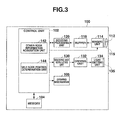
- each moving-object 100 includes a control unit 102, a memory 104, a driving mechanism 105, a lens 112, an imaging unit 114, a buffer 118, a decoding processing unit 120, an encoding and modulating unit 130, a driving unit 132 and a light emitting unit 134.
- the control unit 102 is constituted by, for example, a central processing unit (CPU).
- the control unit 102 performs software processing according to a program (for example, a program for realizing operation of moving-object 100 illustrated in FIGS. 4 and 7 , which will be described later) stored in the memory 104, thereby controlling various functions of moving-object 100.
- the control unit 102 includes an other- node information acquisition unit 142 and a self-node position determination unit 144.
- the memory 104 is, for example, a random access memory (RAM) and a read only memory (ROM).
- the memory 104 stores various information (such as a program) to be used for, for example, control by moving-object 100.
- the driving mechanism 105 includes a motor, a wheel and a steering mechanism for moving moving-object 100.
- the driving mechanism 105 is driven by inputting a control signal based on driving control by the control unit 102, thereby moving moving-object 100.
- the lens 112 is constituted by a zoom lens and a focus lens.
- the lens 112 is operated by focusing control by the control unit 102, thereby controlling an imaging field angle at which the imaging unit 114 takes an image, and an optical image to be taken by the imaging unit 114.
- the imaging unit 114 is constituted by light receiving elements that are regularly and two-dimensionally arranged on a light receiving surface 115.
- the light receiving elements are imaging devices such as charge coupled devices (CCD) and complementary metal oxide semiconductors (CMOS).
- CCD charge coupled devices
- CMOS complementary metal oxide semiconductors
- the imaging unit 114 takes an optical image (receives light ) incident through the lens 112 at an imaging field angle within a predetermined range on the basis of a control signal from the control unit 102, and converts an image signal within the imaging field angle to digital data to generate a frame.
- the imaging unit 114 continuously performs imaging and frame generation, sequentially stores and updates consecutive frames in the buffer 118.
- the control unit 102 determines whether there is a brightness change with time in the same pixel region of the frames sequentially imaged. If a brightness in a pixel region is more than or equal to a first predetermined value in any one frame and is less than or equal to a second predetermined value in any different one frame, it is determined that a brightness of the pixel region has changed due to flashing of light of another moving-object 100 or the reference light source 200.
- the control unit 102 determines as described above, stores or updates, information indicative of a position of an outer edge of this pixel region (hereinafter referred to as "a bright spot region") (bright spot region range information), and a bit data array generated in such a way that an aspect (light-on and light-off) of a brightness change with time over a predetermined number of frames in the bright spot region are represented by "1" and "0" respectively, in a coordinate data list in the buffer 118. If there are more than one bright spot regions, the control unit 102 generates, for each of the bright spot regions, bright spot region range information and a bit data array.
- the decoding processing unit 120 decodes, on the basis of a control signal from the control unit 102, the bit data array indicative of an aspect of a brightness change stored in the coordinate data list in the buffer 118 to digital data.
- a decoding method a method corresponding to an encoding method of the encoding and modulating unit 130 in other moving-objects 100 and the reference light source 200 is adopted.
- the encoding and modulating unit 130 encodes data outputted from the control unit 102 to a bit data array. Further, the encoding and modulating unit 130 performs digital modulation based on the bit data array. Any encoding method and modulation method can be adopted, but 4 pulse position modulation (PPM) using a subcarrier with a frequency of 28.8 (kHz) is preferably adopted as a modulation method.
- PPM pulse position modulation
- the driving unit 132 responds to a signal outputted from the encoding and modulating unit 130 to generate a driving signal for changing a brightness of light emitted from the light emitting unit 134 with time.
- a driving signal instructs to increase a brightness to more than or equal to the first predetermined value at a timing when a pulse exists corresponding to a bit "1", and instructs to decrease a brightness to less than or equal to the second predetermined value at a timing where a pulse does not exist corresponding to a bit "0" (provided, the second predetermined value ⁇ the first predetermined value).
- the light emitting unit 134 emits light whose brightness changes with time to more than or equal to the first predetermined value and to less than or equal to the second predetermined value from a light emitting surface 135 according to a driving signal outputted from the driving unit 132.
- the light emitting surface 135 has a circular shape whose diameter is, for example, about 5 cm, which is much smaller than a light emitting surface of the reference light source 200.
- moving-object 100 emits a self-node information 300 (a first self-node information) light that is information on the moving-object 100 (self-node).
- a self-node information 300 a first self-node information
- the control unit 102 generates the first self-node information.
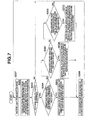
- the above first self-node information 300 includes self-node ID 301, self-light-source shape information 302, position identification state information 303, self-node position information 304 and self-node orientation information 305.
- the self-node ID 301 is identification information to identify a corresponding self-node moving-object 100 from other-node moving-objects 100.
- the self-light-source shape information 302 is vector information indicative of a shape and size of the light emitting surface 135 of the light emitting unit 134 in the self-node moving-object 100.
- the position identification state information 303 is information that indicates which of the following states the self-node moving-object 100 is in:
- the self-node position information 304 is information of an absolute position (coordinates) in the workspace in the above absolute position identified state.
- the self-node orientation information 305 is information indicative of an absolute orientation that is imaged (light-received) by the imaging unit 114 in the self-node moving-object 100, based on a center of a field angle of the imaging surface (light receiving surface) 115 in the above absolute position identified position.
- the control unit 102 stores the first self-node information 300 in the memory 104.
- the control unit 102 also outputs the first self-node information 300 to the encoding and modulating unit 130.
- the encoding and modulating unit 130 encodes the first self-node information 300 outputted from the control unit 102 to a bit data array. Further, the encoding and modulating unit 130 modulates the bit data array to a brightness modulation signal whose brightness changes with time and outputs the brightness modulation signal.
- the driving unit 132 generates a driving signal according to the signal outputted from the encoding and modulating unit 130.
- the light emitting unit 134 emits a first self-node information light corresponding to the first self-node information 300 from the light emitting surface 135 in response to the driving signal.
- the self-node moving-object 100 receives light from another-node moving-object 100.
- the imaging unit 114 takes an optical image (receives light) incident through the lens 112 at an imaging field angle, converts an image signal within the imaging field angle to digital data to sequentially generate frames, sequentially stores and updates these frames in the buffer 118.
- the control unit 102 determines whether there is a change with time in a brightness of the same pixel region in the frames sequentially imaged.
- a brightness of a pixel region is more than or equal to the first predetermined value in any one frame and is less than or equal to the second predetermined value in any different one frame, it is determined that a brightness of the pixel region has changed due to flashing of light of another moving-object 100 and the reference light source 200.
- the control unit 102 stores or updates, information indicative of a position of an outer edge of the pixel region (hereinafter, referred to as "a bright spot region") (bright spot region range information), as well as a bit data array generated in such a way that an aspect of a brightness change (light-on and light-off) with time in the bright spot region over a predetermined frames are represented by "1" and "0" respectively, in a coordinate data list in the buffer 118. If there are more than one bright spot regions, the control unit 102 generates bright spot region range information and a bit data array for each of the bright spot regions.
- the decoding processing unit 120 decodes a bit data array indicative of an aspect of a brightness change stored in the coordinate data list in the buffer 118 to digital data and outputs the digital data to the control unit 102.
- the self-node moving-object 100 modulates first other- node information 400 of another-node moving-object 100 the self-node moving-object 100 has received, and emits the modulated information as a first other-node information light.
- the other-node information acquisition unit 142 in the control unit 102 determines whether digital data from the decoding processing unit 120 is second self-node information that is information on another-node moving-object 100. For example, if digital data is digital data illustrated in FIG. 5 and a region of the self-node ID 301 in FIG. 5 contains ID of another-node moving-object 100, the other- node information acquisition unit 142 determines that this digital data is second self-node information 300.
- the other- node information acquisition unit 142 If digital data is second self-node information 300, the other- node information acquisition unit 142 generates first other-node information 400 that is information on another-node moving-object 100. As illustrated in FIG.6 , the first other- node information 400 is constituted by self-node ID 301, another-node ID 401, corresponding relationship information 402 between self-node and another-node and another- node orientation information 403.
- Self-node ID 301 is identification information of the self-node moving-object 100.
- Another node ID 401 is identification information of another-node moving-object 100.
- corresponding relationship information 402 between self-node and another-node is stored information indicative of:
- the other-node information acquisition unit 142 outputs the generated first other-node information 400 to the encoding and modulating unit 130.
- the encoding and modulating unit 130 encodes the first other- node information 400 outputted from the control unit 102 to a bit data array. Further, the encoding and modulating unit 130 modulates the bit data array to a brightness modulation signal whose brightness changes with time and outputs the signal.
- the driving unit 132 generates a driving signal according to the signal outputted from the encoding and modulating unit 130.
- the light emitting unit 134 emits a first other-node information light corresponding to the first other-node information 400 from the light emitting surface 135, in response to the driving signal.
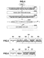
- Step S104 the control unit 102 in the self-node moving-object 100 determines, for example, whether data for the moving-object 100 to realize a service has to be transmitted.
- Step S105 If the above data has to be transmitted, light modulated corresponding to normal data is emitted at Step S105.
- a specific method is the same as the method at Step S101 and Step S103.
- the self-node moving-object 100 receives light from another moving-object 100 and the reference light source 200 at Step S201 as illustrated in FIG. 7 .
- the imaging unit 114 takes an optical image (receives light) incident through the lens 112 at an imaging field angle within a predetermined range on the basis of a control signal from the control unit 102, and converts an image signal within the imaging field angle to digital data, thereby generating a frame.
- the imaging unit 114 continuously performs imaging and frame generation, and sequentially stores and updates consecutive frames in the buffer 118.
- the control unit 102 determines whether a brightness in the same pixel region changes with time for frames sequentially imaged.
- a brightness in a pixel region is more than or equal to the first predetermined value in any one frame and is less than or equal to the second predetermined value in any different one frame, it is determined that a brightness in the pixel region has changed due to flashing of light of another moving-object 100 or the reference light source 200.
- the control unit 102 stores or updates information indicative of a position of an outer edge of the pixel region (hereinafter will be referred to as "a bright spot region") (bright spot region range information) and a bit data array generated in such a way that an aspect of a brightness change (light-on and light-off) with time over a predetermined number of frames in the bright spot region are represented by "1" and "0" respectively in a coordinate data list in the buffer 118. If there are more than one bright spot regions, the control unit 102 generates bright spot region range information and a bit data array for each of the bright spot regions.
- the self-node moving-object 100 stores or updates second self-node information 300 that is information on another moving-object 100, which is a source of light received by the self-node moving-object 100 and second other-node information 400 that is information on itself (self-node) in association with bright spot region range information.
- the self-node position determination unit 144 in the control unit 102 determines whether digital data from the decoding processing unit 120 is second self-node information 300 that is information on another moving-object 100 (another-node). For example, if the digital data has a structure illustrated in FIG.5 and a region of self-node ID 301 in FIG.5 contains ID other than ID of the self-node moving-object 100, the self-node position determination unit 144 determines that the digital data is second self-node information 300. If the digital data is second self-node information 300, the self-node position determination unit 144 stores this second self-node information 300 and bright spot region range information corresponding thereto in the memory 104. If the memory 104 already stores second self-node information 300 that contains self-node ID identical to self-node ID 301, the self-node position determination unit 144 updates second self-node information 300 and bright spot region range information.
- the self-node position determination unit 144 determines whether digital data from the decoding processing unit 120 is second other-node information 400 that is information on moving-object 100 (self-node). This determination method will be specifically described. In FIG. 6 , if a region of self-node ID 301 contains ID other than ID of the self-node moving-object 100 and a region of other node ID 401 contains ID of the self-node moving-object 100, the self-node position determination unit 144 determines that this digital data is second other-node information 400. If it is determined as above, the self-node position determination unit 144 stores bright spot region range information corresponding to second other-node information 400 in the memory 104. If the memory 104 already stores second other-node information 400 containing self-node ID identical to self-node ID 301, the self-node position determination unit 144 updates second other-node information 400 and bright spot region range information.
- the self-node moving-object 100 determines whether an absolute position thereof has been identified. Specifically, if the memory 104 stores first self-node information 300, and position determination state information in the first self-node information indicates absolute position identified state, the self-node position determination unit 144 determines an absolute position of the self-node moving-object 100 has been identified. Otherwise, the self-node position determination unit 144 determines that an absolute position of the self-node moving-object 100 has not been identified.
- the control unit 102 determines that an absolute position of the self-node moving-object 100 has been identified at Step S203 (Step S203; Yes), and determines, for a bright spot region corresponding to light received at Step S201, whether there is a bright spot region having the number of pixels more than or equal to a threshold value at Step S204. Specifically, the self-node position determination unit 144 counts the number of pixels of the bright spot region on the basis of bright spot region range information stored in the memory 104, and determines whether the counted number of pixels is more than or equal to a threshold value. If there are more than one bright spot regions in a frame, the self-node position determination unit 144 counts the number of pixels for each of the bright spot regions, and determines whether the number of pixels of the region is more than or equal to a threshold value.
- Step S204 if it is determined that there is a bright spot region having the number of pixels more than or equal to a threshold value (Step S204; Yes), the self-node moving-object 100 identifies an absolute position and absolute orientation thereof by analysis of a shape of the bright spot region at Step S205.
- FIG.8A an image (frame) photographed by moving-object 100A is illustrated in FIG.8A
- FIG.8B an image (frame) photographed by moving-object 100B is illustrated in FIG.8B
- FIG.8C an image (frame) photographed by moving-object 100C is illustrated in FIG.8C .
- Each of the images contains a bright spot region 201 having a unique shape corresponding to light from the reference light source 200.
- the self-node position determination unit 144 in each of moving-object 100A, 100B, 100C analyzes a shape of the bright spot region 201 on the basis of bright spot region range information, thereby identifying an absolute position and absolute orientation of the self-node moving-object 100.
- the self-node moving-object 100 determines whether there are three or more other-node moving-objects 100 whose absolute positions have been identified at Step S207. Specifically, the self-node position determination unit 144 determines whether there are three or more two pieces of second self-node information 300 whose position identification state information 303 indicates an absolute position identified state, of second self-node information 300 stored in the memory 104.
- Step S207 If there are three or more other moving-objects 100 (other nodes) whose absolute positions have been identified (Step S207; Yes), the self-node moving-object 100 identifies an absolute position thereof on the basis of absolute position information from three other moving-objects 100 whose absolute positions have been identified at Step S208.
- the self-node position determination unit 144 reads out self-node position information 304 contained in each of three pieces of second self-node information 300 stored in the memory 104.
- the read-out self-node position information 304 indicates absolute positions of the other-node moving-objects 100.
- the read-out self-node position information 304 will be referred to as absolute position information of the other-node moving-objects 100.
- the self-node position determination unit 144 reads out bright spot region range information contained in each of the read-out three pieces of second self-node information 300 from the memory 104. Further, the self-node position determination unit 144 recognizes positions of bright spot regions in a frame, each corresponding to light from each of the three other moving-objects 100 on the basis of the bright spot region range information. For example, if the moving-objects 100 are arranged as illustrated in FIG. 1 and FIG. 2 , an image (frame) photographed by moving-object 100D is illustrated in FIG.8D .
- a bright spot region 101A corresponding to light from moving-object 100A
- a bright spot region 101B corresponding to light from moving-object 100B
- a bright spot region 101C corresponding to light from moving-object 100C
- a bright spot region 101E corresponding to light from moving-object 100E. If a position of the bright spot region 101E is a reference position, an apparent angle of the bright spot region 101A is - a degrees, an apparent angle of the bright spot region 101B is b degrees, and an apparent angle of the bright spot region 101C is c degrees.
- the above processing identifies absolute positions of the three other moving-objects 100 and apparent angles of the bright spot regions, each corresponding to light from each of the three other moving-objects 100.
- the self-node position determination unit 144 can determine an absolute position of the self-node moving-object 100 on the basis of the absolute positions of the three other moving-objects 100 and the apparent angles of the bright spot regions corresponding to light from the three other moving-objects 100.
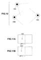
- moving-object 100D determines an absolute position thereof.
- absolute positions of moving-object 100A and 100B have been identified and an apparent angle (a view angle) between moving-object 100A and moving-object 100B is (a + b) degrees.
- moving-object 100D exists on an arc represented by a dot line in FIG. 9A on the basis of the circumferential angle theorem.
- the absolute positions of moving-objects 100B and 100C have been identified, and an apparent angle (a view angle) between moving-object 100B and moving-object 100C is (c - b) degrees.
- moving-object 100D exists on an arc represented by a dot line in FIG. 9B on the basis of the circumferential angle theorem. Therefore, an absolute position of moving-object 100D is an intersection of two arcs represented by the dot lines, as illustrated in FIG. 9C .
- Step S207 determines whether to have acquired orientation information of the self-node moving-object 100 (other-node orientation information 403) from two other-node moving-objects 100 whose absolute positions have been identified at Step S209.
- the self-node position determination unit 144 determines whether memory 104 has stored two or more pieces of second other-node information 400 that contain "absolute” in corresponding relationship information 402. If the memory 104 has two or more piece of second other-node information 400 that contain "absolute” in the corresponding relationship information 402, the self-node position determination unit 144 further determines whether these pieces of second other-node information 400 contain other-node orientation information 403.
- Step S209 If it is determined that orientation information of the self-node moving-object 100 has been acquired from two other-node moving-objects 100 whose absolute positions have been identified at Step S209 (Step S209; Yes), the self-node moving-object 100 reads out the absolute position information and other-node orientation information 403 from the two other-node moving-objects 100 whose absolute positions have been identified, and identifies an absolute position of the self-node moving-object 100 on the basis of the read-out information at Step S210.
- the self-node position determination unit 144 reads out self-node position information 304 in two pieces of second self-node information 300 that contain self-node ID identical to self-node ID 301 in the two pieces of second other-node information 400.
- the read-out other-node orientation information 403 indicates absolute orientations from positions of the other-node moving-objects 100 to self-node moving-object 100
- the read-out self-node position information 304 indicates absolute positions of the other-node moving-objects 100.
- the read-out other-node orientation information 403 will be referred to as absolute orientation information of the self-node moving-object 100
- the read-out self-node position information 304 will be referred to as absolute position information of the other-node moving-objects 100.
- the self-node position determination unit 144 reads out bright spot region range information corresponding to each of two pieces of second self-node information 300 containing the read-out absolute position information from the memory 104. Further, the self-node position determination unit 144 recognizes positions of bright spot regions in a frame corresponding to lights from the two other-node moving-objects 100 on the basis of the bright spot region range information.
- the moving-objects 100 are arranged as illustrated in FIG. 10 and moving-object 100C identifies an absolute position thereof will be described.
- FIG. 11A a frame photographed by moving-object 100A is illustrated in FIG. 11A .
- the frame photographed by moving-object 100A contains a bright spot region 101C corresponding to light from moving-object 100C.
- an apparent angle of the bright spot region 101C is - ⁇ 2 degrees
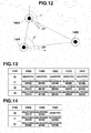
- an absolute orientation of a central axis of the light receiving surface 115 in the imaging unit 114 in moving-object 100A is ⁇ degrees as illustrated in FIG.12
- an absolute orientation from a position of moving-object 100A to moving-object 100C is ⁇ - ⁇ 2 degrees.
- This value is contained in other-node orientation information 403 in other-node information 400 from moving-object 100A to moving-object 100C.
- FIG.11B An image (frame) photographed by moving-object 100B is illustrated in FIG.11B .
- the frame photographed by moving-object 100B contains a bright spot region 101C corresponding to light from moving-object 100C.
- an apparent angle of the bright spot region 101C is - ⁇ 2 degrees and an absolute orientation of a central axis of the light receiving surface 115 in the imaging unit 114 in moving-object 100B is ⁇ degrees as illustrated in FIG. 12
- an absolute orientation from a position of moving-object 100B to moving-object 100C is ( ⁇ - ⁇ 2) degrees.
- This value is contained in other-node orientation information 403 in other-node information 400 from moving-object 100B to moving-object 100C.
- the above processing identifies absolute positions and absolute orientations of the two other-node moving-objects 100.
- the self-node position determination unit 144 can identify an absolute position thereof on the basis of the absolute positions and absolute orientations of the two other-node moving-objects 100. For example, as illustrated in FIG. 12 , an intersection of a straight line drawn at an absolute orientation angle of ( ⁇ - ⁇ 2) degrees from an absolute position of moving-object 100A and a straight line drawn at an absolute orientation angle of ( ⁇ - ⁇ 2 degrees) from an absolute position of moving-object 100B is an absolute position of moving-object 100C.
- the self-node moving-object 100 After an absolute position of the self-node moving-object 100 has been identified at Steps S205, S208 or S210, the self-node moving-object 100 stores information of an absolute position and absolute orientation thereof at Step S206. Further, the self-node moving-object 100 changes a state thereof into an absolute position identified state. Specifically, the self-node position determination unit 144 stores information of the identified absolute position of the self-node moving-object 100 in the memory 104. If an absolute orientation has been identified at Step S205, the self-node position determination unit 144 also stores information of the identified absolute orientation of the self-node moving-object 100 in the memory 104. The stored information of absolute position and absolute orientation of the self-node moving-object 100 and information indicative of absolute position identified state will be used later for generation of first self-node information 300 and first other- node information 400.
- each moving-object 100 in workspace receives light from three other-node moving-objects 100 to acquire information of absolute positions of the other-node moving-objects 100, thereby identifying an absolute position of itself.
- Each moving-object 100 if no moving-object 100 has identified an absolute position thereof, receives light from the reference light source 200, thereby identifying an absolute position of itself.
- a moving-object 100 receives light from the reference light source 200 to identify an absolute position thereof, and emits light modulated corresponding to information of the absolute position, enabling another moving-object 100 that cannot receive light from the reference light source 200 to identify an absolute position thereof, which increases the number of moving-objects 100 that have identified absolute positions of themselves as time passes.
- moving-objeets100 are arranged as illustrated in FIG. 1 and FIG. 2 and the number of moving-objects 100 that have identified absolute positions of themselves increases as time passes will be described.
- moving-objects 100A to 100E have not identified absolute positions of themselves.
- moving-objects 100A to 100E take photographs; a frame photographed by moving-object 100A is illustrated in FIG. 8A , a frame photographed by moving-object 100B is illustrated in FIG. 8B , a frame photographed by moving-object 100C is illustrated in FIG. 8C , a frame photographed by moving-object 100D is illustrated in FIG. 8D , and a frame photographed by moving-object 100E is illustrated in FIG. 8E .
- each of the frames illustrated in FIGS. 8A to 8C contains a brightness region 201 corresponding to the reference light source 200. Therefore, moving-objects 100A, 100B and 100C can identify absolute positions of themselves at time t1, as illustrated in FIG.13 .
- moving-object 100D only receives light from three moving-objects 100A, 100B and 100C whose absolute positions have been identified, and therefore can identify only a relative position of moving-object 100D, as illustrated in FIG.8D .
- moving-object 100E receives only light from two moving-objects 100B and 100C whose absolute positions have been identified as illustrated in FIG.8E , and therefore cannot identify an absolute position or a relative position of moving-object 100E.
- moving-object 100D receives, from three moving-objects 100A, 100B and 100C whose absolute positions have been identified, light modulated corresponding to information of their absolute positions, and therefore can identify an absolute position of moving-object 100D.
- moving-object 100E is in a state immediately after the moving-object D receives, from two moving-objects 100B and 100C whose absolute positions have been identified, light modulated corresponding to information of these absolute positions and therefore identifies only a relative position of moving-object 100E.
- moving-object 100E can receive, from three moving-objects 100B, 100C and 100D whose absolute positions have been identified, light modulated corresponding to information of these absolute positions and therefore can identify an absolute position of moving-object 100E.
- each moving-object 100 can determine absolute position thereof and therefore can increase a certainty of position recognition.
- a self-node moving-object 100 in the workspace receives light from two other-node moving-objects 100 to acquire information of absolute positions of the two other-node moving-objects 100 and information of absolute orientations from positions of the two other-node moving-objects to the self-node moving-object 100. This can identify an absolute position of the self-node moving-object 100.
- moving-objects 100 are arranged as illustrated in FIG. 10
- FIG. 10 For example, a case where moving-objects 100 are arranged as illustrated in FIG. 10 will be described.
- another moving-object 100C can identify an absolute position thereof.
- At least two moving-objects 100 can identify absolute positions and absolute orientations of themselves in this way, another moving-object 100 can identify an absolute position of itself, which can increase a certainty of position recognition.
- the reference light source 200 exists in the workspace, but this configuration is not essential. Without a reference light source in the workspace, when at least two moving-objects are introduced into the workspace, their absolute positions are recognized and if each moving-object moves after a predetermined time, the movement can update its absolute position.
- the present invention can be similarly applied to a different mobile body having a light source or a fixed device.
- a device and a system that preliminarily includes a configuration for realizing a function according to the present invention can be provided, and also an existing apparatus can function as a device and a system according to the present invention by applying a program to the existing apparatus.
- Any method to apply a program can be employed; for example, a program can be stored in a computer-readable recording medium such as a CD-ROM, a DVD-ROM and a memory card, or a program can be applied through a communication medium such as the Internet.
Landscapes
- Engineering & Computer Science (AREA)
- Computer Vision & Pattern Recognition (AREA)
- Physics & Mathematics (AREA)
- General Physics & Mathematics (AREA)
- Theoretical Computer Science (AREA)
- Image Analysis (AREA)
- Control Of Position, Course, Altitude, Or Attitude Of Moving Bodies (AREA)
- Manipulator (AREA)
- Length Measuring Devices By Optical Means (AREA)
Applications Claiming Priority (1)
| Application Number | Priority Date | Filing Date | Title |
|---|---|---|---|
| JP2011215700A JP5348215B2 (ja) | 2011-09-29 | 2011-09-29 | 情報取得装置、情報取得方法、情報取得プログラム、及び、情報取得システム |
Publications (3)
| Publication Number | Publication Date |
|---|---|
| EP2575105A2 true EP2575105A2 (de) | 2013-04-03 |
| EP2575105A3 EP2575105A3 (de) | 2015-01-21 |
| EP2575105B1 EP2575105B1 (de) | 2018-03-21 |
Family
ID=47044830
Family Applications (1)
| Application Number | Title | Priority Date | Filing Date |
|---|---|---|---|
| EP12186307.0A Not-in-force EP2575105B1 (de) | 2011-09-29 | 2012-09-27 | Informationserfassungsvorrichtung, Informationsverfassungsverfahren, Programm und Informationserfassungssystem |
Country Status (4)
| Country | Link |
|---|---|
| US (1) | US8921752B2 (de) |
| EP (1) | EP2575105B1 (de) |
| JP (1) | JP5348215B2 (de) |
| CN (1) | CN103033792B (de) |
Families Citing this family (10)
| Publication number | Priority date | Publication date | Assignee | Title |
|---|---|---|---|---|
| DE102015109775B3 (de) | 2015-06-18 | 2016-09-22 | RobArt GmbH | Optischer Triangulationssensor zur Entfernungsmessung |
| DE102015114883A1 (de) * | 2015-09-04 | 2017-03-09 | RobArt GmbH | Identifizierung und Lokalisierung einer Basisstation eines autonomen mobilen Roboters |
| DE102015119501A1 (de) | 2015-11-11 | 2017-05-11 | RobArt GmbH | Unterteilung von Karten für die Roboternavigation |
| DE102015119865B4 (de) | 2015-11-17 | 2023-12-21 | RobArt GmbH | Robotergestützte Bearbeitung einer Oberfläche mittels eines Roboters |
| DE102015121666B3 (de) | 2015-12-11 | 2017-05-24 | RobArt GmbH | Fernsteuerung eines mobilen, autonomen Roboters |
| DE102016102644A1 (de) | 2016-02-15 | 2017-08-17 | RobArt GmbH | Verfahren zur Steuerung eines autonomen mobilen Roboters |
| CN109804325A (zh) | 2016-08-05 | 2019-05-24 | 罗伯特有限责任公司 | 用于控制自主移动机器人的方法 |
| EP3532859B1 (de) | 2016-10-31 | 2025-12-10 | Vizar Technologies Sàrl | Verfahren und vorrichtung zur erkennung von lichtmodulierten signalen in einem videostrom |
| EP3974934A1 (de) | 2017-03-02 | 2022-03-30 | Robart GmbH | Verfahren zur steuerung eines autonomen, mobilen roboters |
| DE102017109219A1 (de) | 2017-04-28 | 2018-10-31 | RobArt GmbH | Verfahren für die Roboternavigation |
Citations (3)
| Publication number | Priority date | Publication date | Assignee | Title |
|---|---|---|---|---|
| JP2005115500A (ja) | 2003-10-06 | 2005-04-28 | Mitsubishi Electric Corp | 情報処理装置及び情報処理方法 |
| JP2008039494A (ja) | 2006-08-03 | 2008-02-21 | Casio Comput Co Ltd | 情報取得装置、情報取得方法、情報取得プログラム、及び、測定システム |
| JP2009118178A (ja) | 2007-11-06 | 2009-05-28 | Toshiba Corp | 個体情報識別システム |
Family Cites Families (6)
| Publication number | Priority date | Publication date | Assignee | Title |
|---|---|---|---|---|
| CN1083242A (zh) * | 1992-08-15 | 1994-03-02 | 华中理工大学 | 公交车辆监控数据采集系统 |
| IL106544A (en) * | 1993-08-01 | 1996-10-16 | Israel State | Area surveying apparatus for communication system |
| JP4401564B2 (ja) * | 2000-12-12 | 2010-01-20 | 本田技研工業株式会社 | 自律ロボット、集中制御装置、自律ロボットの行動計画策定方法、自律ロボットの集中制御方法、自律ロボットの行動計画策定プログラムを記録した記録媒体、自律ロボットの集中制御プログラムを記録した記録媒体 |
| JP3914906B2 (ja) * | 2003-08-13 | 2007-05-16 | 株式会社東芝 | 自走式移動装置及び位置補正方法 |
| KR100863245B1 (ko) * | 2006-07-18 | 2008-10-15 | 삼성전자주식회사 | 거리측정 기능을 갖는 비컨, 이를 이용한 위치인식시스템및 그 위치인식방법 |
| JP2011134058A (ja) * | 2009-12-24 | 2011-07-07 | B-Core Inc | 光学式自己位置検知装置及び方法 |
-
2011
- 2011-09-29 JP JP2011215700A patent/JP5348215B2/ja active Active
-
2012
- 2012-09-27 EP EP12186307.0A patent/EP2575105B1/de not_active Not-in-force
- 2012-09-27 CN CN201210374407.1A patent/CN103033792B/zh active Active
- 2012-09-28 US US13/630,845 patent/US8921752B2/en active Active
Patent Citations (3)
| Publication number | Priority date | Publication date | Assignee | Title |
|---|---|---|---|---|
| JP2005115500A (ja) | 2003-10-06 | 2005-04-28 | Mitsubishi Electric Corp | 情報処理装置及び情報処理方法 |
| JP2008039494A (ja) | 2006-08-03 | 2008-02-21 | Casio Comput Co Ltd | 情報取得装置、情報取得方法、情報取得プログラム、及び、測定システム |
| JP2009118178A (ja) | 2007-11-06 | 2009-05-28 | Toshiba Corp | 個体情報識別システム |
Also Published As
| Publication number | Publication date |
|---|---|
| US20130082167A1 (en) | 2013-04-04 |
| US8921752B2 (en) | 2014-12-30 |
| JP2013077088A (ja) | 2013-04-25 |
| CN103033792B (zh) | 2015-06-17 |
| EP2575105A3 (de) | 2015-01-21 |
| EP2575105B1 (de) | 2018-03-21 |
| CN103033792A (zh) | 2013-04-10 |
| JP5348215B2 (ja) | 2013-11-20 |
Similar Documents
| Publication | Publication Date | Title |
|---|---|---|
| US8921752B2 (en) | Information acquisition device, information acquisition method, recording medium, and information acquisition system | |
| US11338920B2 (en) | Method for guiding autonomously movable machine by means of optical communication device | |
| TW200813462A (en) | Mobile device tracking | |
| KR102345777B1 (ko) | 광학 카메라 통신(occ) 기반 차량 위치 판단 방법 및 장치 | |
| US20190280770A1 (en) | Method and apparatus for free-space optical transmission | |
| US10218439B2 (en) | Optical communication device, optical communication method, and non-transitory recording medium | |
| CN108781268B (zh) | 图像处理装置和方法 | |
| US10365373B2 (en) | Vehicle-mountable distance measurement device | |
| TW201947893A (zh) | 對能夠自主移動的機器進行導引的系統和方法 | |
| US10284795B2 (en) | Image processing device, image processing method, and image processing program which control a scan frequency of an imaging unit | |
| JP4224487B2 (ja) | 位置検出システム | |
| JP2007295490A (ja) | 可視光通信装置および可視光受信方法 | |
| CN106716511B (zh) | 遥控设备、用户设备及其系统,以及方法和识别信号 | |
| US20230214615A1 (en) | Remote barcodes decoding | |
| CN114694145A (zh) | 作为视场识别和瞄准的双照明器 | |
| JP5414379B2 (ja) | 光無線通信装置、光無線通信方法、およびプログラム | |
| KR100876821B1 (ko) | 촬영 영역 내에서 정확하게 얼굴 영상을 촬영하는 장치 | |
| JP2015095225A (ja) | 情報生成装置、情報生成方法、及び、情報生成プログラム | |
| CN109564084B (zh) | 记录介质、位置推断装置以及位置推断方法 | |
| JP2015130597A (ja) | 動体検知装置 | |
| JP2007043579A (ja) | 対象物識別システム及び検出装置 | |
| CN110736965B (zh) | 一种可见光定位的二维编码与解码方法 | |
| JP6827598B1 (ja) | 画像ベースのサービスのためのデバイス | |
| CN112788311B (zh) | 信息获取方法、信息获取装置 | |
| JP2008026731A (ja) | マーカー装置 |
Legal Events
| Date | Code | Title | Description |
|---|---|---|---|
| PUAI | Public reference made under article 153(3) epc to a published international application that has entered the european phase |
Free format text: ORIGINAL CODE: 0009012 |
|
| 17P | Request for examination filed |
Effective date: 20120927 |
|
| AK | Designated contracting states |
Kind code of ref document: A2 Designated state(s): AL AT BE BG CH CY CZ DE DK EE ES FI FR GB GR HR HU IE IS IT LI LT LU LV MC MK MT NL NO PL PT RO RS SE SI SK SM TR |
|
| AX | Request for extension of the european patent |
Extension state: BA ME |
|
| PUAL | Search report despatched |
Free format text: ORIGINAL CODE: 0009013 |
|
| AK | Designated contracting states |
Kind code of ref document: A3 Designated state(s): AL AT BE BG CH CY CZ DE DK EE ES FI FR GB GR HR HU IE IS IT LI LT LU LV MC MK MT NL NO PL PT RO RS SE SI SK SM TR |
|
| AX | Request for extension of the european patent |
Extension state: BA ME |
|
| RIC1 | Information provided on ipc code assigned before grant |
Ipc: G06T 7/00 20060101AFI20141215BHEP |
|
| 17Q | First examination report despatched |
Effective date: 20170330 |
|
| REG | Reference to a national code |
Ref country code: DE Ref legal event code: R079 Ref document number: 602012044135 Country of ref document: DE Free format text: PREVIOUS MAIN CLASS: G06T0007000000 Ipc: G06T0007730000 |
|
| RIC1 | Information provided on ipc code assigned before grant |
Ipc: G06T 7/73 20170101AFI20170818BHEP |
|
| GRAP | Despatch of communication of intention to grant a patent |
Free format text: ORIGINAL CODE: EPIDOSNIGR1 |
|
| RAP1 | Party data changed (applicant data changed or rights of an application transferred) |
Owner name: CASIO COMPUTER CO., LTD. |
|
| INTG | Intention to grant announced |
Effective date: 20171013 |
|
| GRAS | Grant fee paid |
Free format text: ORIGINAL CODE: EPIDOSNIGR3 |
|
| GRAA | (expected) grant |
Free format text: ORIGINAL CODE: 0009210 |
|
| AK | Designated contracting states |
Kind code of ref document: B1 Designated state(s): AL AT BE BG CH CY CZ DE DK EE ES FI FR GB GR HR HU IE IS IT LI LT LU LV MC MK MT NL NO PL PT RO RS SE SI SK SM TR |
|
| REG | Reference to a national code |
Ref country code: GB Ref legal event code: FG4D |
|
| REG | Reference to a national code |
Ref country code: CH Ref legal event code: EP |
|
| REG | Reference to a national code |
Ref country code: AT Ref legal event code: REF Ref document number: 981868 Country of ref document: AT Kind code of ref document: T Effective date: 20180415 |
|
| REG | Reference to a national code |
Ref country code: IE Ref legal event code: FG4D |
|
| REG | Reference to a national code |
Ref country code: DE Ref legal event code: R096 Ref document number: 602012044135 Country of ref document: DE |
|
| REG | Reference to a national code |
Ref country code: NL Ref legal event code: MP Effective date: 20180321 |
|
| PG25 | Lapsed in a contracting state [announced via postgrant information from national office to epo] |
Ref country code: CY Free format text: LAPSE BECAUSE OF FAILURE TO SUBMIT A TRANSLATION OF THE DESCRIPTION OR TO PAY THE FEE WITHIN THE PRESCRIBED TIME-LIMIT Effective date: 20180321 Ref country code: HR Free format text: LAPSE BECAUSE OF FAILURE TO SUBMIT A TRANSLATION OF THE DESCRIPTION OR TO PAY THE FEE WITHIN THE PRESCRIBED TIME-LIMIT Effective date: 20180321 Ref country code: NO Free format text: LAPSE BECAUSE OF FAILURE TO SUBMIT A TRANSLATION OF THE DESCRIPTION OR TO PAY THE FEE WITHIN THE PRESCRIBED TIME-LIMIT Effective date: 20180621 Ref country code: FI Free format text: LAPSE BECAUSE OF FAILURE TO SUBMIT A TRANSLATION OF THE DESCRIPTION OR TO PAY THE FEE WITHIN THE PRESCRIBED TIME-LIMIT Effective date: 20180321 Ref country code: LT Free format text: LAPSE BECAUSE OF FAILURE TO SUBMIT A TRANSLATION OF THE DESCRIPTION OR TO PAY THE FEE WITHIN THE PRESCRIBED TIME-LIMIT Effective date: 20180321 |
|
| REG | Reference to a national code |
Ref country code: LT Ref legal event code: MG4D |
|
| REG | Reference to a national code |
Ref country code: FR Ref legal event code: PLFP Year of fee payment: 7 |
|
| REG | Reference to a national code |
Ref country code: AT Ref legal event code: MK05 Ref document number: 981868 Country of ref document: AT Kind code of ref document: T Effective date: 20180321 |
|
| PG25 | Lapsed in a contracting state [announced via postgrant information from national office to epo] |
Ref country code: LV Free format text: LAPSE BECAUSE OF FAILURE TO SUBMIT A TRANSLATION OF THE DESCRIPTION OR TO PAY THE FEE WITHIN THE PRESCRIBED TIME-LIMIT Effective date: 20180321 Ref country code: SE Free format text: LAPSE BECAUSE OF FAILURE TO SUBMIT A TRANSLATION OF THE DESCRIPTION OR TO PAY THE FEE WITHIN THE PRESCRIBED TIME-LIMIT Effective date: 20180321 Ref country code: RS Free format text: LAPSE BECAUSE OF FAILURE TO SUBMIT A TRANSLATION OF THE DESCRIPTION OR TO PAY THE FEE WITHIN THE PRESCRIBED TIME-LIMIT Effective date: 20180321 Ref country code: BG Free format text: LAPSE BECAUSE OF FAILURE TO SUBMIT A TRANSLATION OF THE DESCRIPTION OR TO PAY THE FEE WITHIN THE PRESCRIBED TIME-LIMIT Effective date: 20180621 Ref country code: GR Free format text: LAPSE BECAUSE OF FAILURE TO SUBMIT A TRANSLATION OF THE DESCRIPTION OR TO PAY THE FEE WITHIN THE PRESCRIBED TIME-LIMIT Effective date: 20180622 |
|
| PG25 | Lapsed in a contracting state [announced via postgrant information from national office to epo] |
Ref country code: AL Free format text: LAPSE BECAUSE OF FAILURE TO SUBMIT A TRANSLATION OF THE DESCRIPTION OR TO PAY THE FEE WITHIN THE PRESCRIBED TIME-LIMIT Effective date: 20180321 Ref country code: ES Free format text: LAPSE BECAUSE OF FAILURE TO SUBMIT A TRANSLATION OF THE DESCRIPTION OR TO PAY THE FEE WITHIN THE PRESCRIBED TIME-LIMIT Effective date: 20180321 Ref country code: NL Free format text: LAPSE BECAUSE OF FAILURE TO SUBMIT A TRANSLATION OF THE DESCRIPTION OR TO PAY THE FEE WITHIN THE PRESCRIBED TIME-LIMIT Effective date: 20180321 Ref country code: RO Free format text: LAPSE BECAUSE OF FAILURE TO SUBMIT A TRANSLATION OF THE DESCRIPTION OR TO PAY THE FEE WITHIN THE PRESCRIBED TIME-LIMIT Effective date: 20180321 Ref country code: IT Free format text: LAPSE BECAUSE OF FAILURE TO SUBMIT A TRANSLATION OF THE DESCRIPTION OR TO PAY THE FEE WITHIN THE PRESCRIBED TIME-LIMIT Effective date: 20180321 Ref country code: EE Free format text: LAPSE BECAUSE OF FAILURE TO SUBMIT A TRANSLATION OF THE DESCRIPTION OR TO PAY THE FEE WITHIN THE PRESCRIBED TIME-LIMIT Effective date: 20180321 Ref country code: PL Free format text: LAPSE BECAUSE OF FAILURE TO SUBMIT A TRANSLATION OF THE DESCRIPTION OR TO PAY THE FEE WITHIN THE PRESCRIBED TIME-LIMIT Effective date: 20180321 |
|
| PGFP | Annual fee paid to national office [announced via postgrant information from national office to epo] |
Ref country code: DE Payment date: 20180727 Year of fee payment: 15 |
|
| PG25 | Lapsed in a contracting state [announced via postgrant information from national office to epo] |
Ref country code: SM Free format text: LAPSE BECAUSE OF FAILURE TO SUBMIT A TRANSLATION OF THE DESCRIPTION OR TO PAY THE FEE WITHIN THE PRESCRIBED TIME-LIMIT Effective date: 20180321 Ref country code: SK Free format text: LAPSE BECAUSE OF FAILURE TO SUBMIT A TRANSLATION OF THE DESCRIPTION OR TO PAY THE FEE WITHIN THE PRESCRIBED TIME-LIMIT Effective date: 20180321 Ref country code: AT Free format text: LAPSE BECAUSE OF FAILURE TO SUBMIT A TRANSLATION OF THE DESCRIPTION OR TO PAY THE FEE WITHIN THE PRESCRIBED TIME-LIMIT Effective date: 20180321 Ref country code: CZ Free format text: LAPSE BECAUSE OF FAILURE TO SUBMIT A TRANSLATION OF THE DESCRIPTION OR TO PAY THE FEE WITHIN THE PRESCRIBED TIME-LIMIT Effective date: 20180321 |
|
| PGFP | Annual fee paid to national office [announced via postgrant information from national office to epo] |
Ref country code: GB Payment date: 20180926 Year of fee payment: 7 |
|
| PG25 | Lapsed in a contracting state [announced via postgrant information from national office to epo] |
Ref country code: PT Free format text: LAPSE BECAUSE OF FAILURE TO SUBMIT A TRANSLATION OF THE DESCRIPTION OR TO PAY THE FEE WITHIN THE PRESCRIBED TIME-LIMIT Effective date: 20180723 |
|
| REG | Reference to a national code |
Ref country code: DE Ref legal event code: R097 Ref document number: 602012044135 Country of ref document: DE |
|
| PLBE | No opposition filed within time limit |
Free format text: ORIGINAL CODE: 0009261 |
|
| STAA | Information on the status of an ep patent application or granted ep patent |
Free format text: STATUS: NO OPPOSITION FILED WITHIN TIME LIMIT |
|
| PG25 | Lapsed in a contracting state [announced via postgrant information from national office to epo] |
Ref country code: DK Free format text: LAPSE BECAUSE OF FAILURE TO SUBMIT A TRANSLATION OF THE DESCRIPTION OR TO PAY THE FEE WITHIN THE PRESCRIBED TIME-LIMIT Effective date: 20180321 |
|
| 26N | No opposition filed |
Effective date: 20190102 |
|
| PG25 | Lapsed in a contracting state [announced via postgrant information from national office to epo] |
Ref country code: MC Free format text: LAPSE BECAUSE OF FAILURE TO SUBMIT A TRANSLATION OF THE DESCRIPTION OR TO PAY THE FEE WITHIN THE PRESCRIBED TIME-LIMIT Effective date: 20180321 |
|
| REG | Reference to a national code |
Ref country code: CH Ref legal event code: PL |
|
| PG25 | Lapsed in a contracting state [announced via postgrant information from national office to epo] |
Ref country code: SI Free format text: LAPSE BECAUSE OF FAILURE TO SUBMIT A TRANSLATION OF THE DESCRIPTION OR TO PAY THE FEE WITHIN THE PRESCRIBED TIME-LIMIT Effective date: 20180321 |
|
| REG | Reference to a national code |
Ref country code: BE Ref legal event code: MM Effective date: 20180930 |
|
| REG | Reference to a national code |
Ref country code: IE Ref legal event code: MM4A |
|
| PG25 | Lapsed in a contracting state [announced via postgrant information from national office to epo] |
Ref country code: LU Free format text: LAPSE BECAUSE OF NON-PAYMENT OF DUE FEES Effective date: 20180927 |
|
| PG25 | Lapsed in a contracting state [announced via postgrant information from national office to epo] |
Ref country code: IE Free format text: LAPSE BECAUSE OF NON-PAYMENT OF DUE FEES Effective date: 20180927 |
|
| PG25 | Lapsed in a contracting state [announced via postgrant information from national office to epo] |
Ref country code: BE Free format text: LAPSE BECAUSE OF NON-PAYMENT OF DUE FEES Effective date: 20180930 Ref country code: CH Free format text: LAPSE BECAUSE OF NON-PAYMENT OF DUE FEES Effective date: 20180930 Ref country code: LI Free format text: LAPSE BECAUSE OF NON-PAYMENT OF DUE FEES Effective date: 20180930 |
|
| PG25 | Lapsed in a contracting state [announced via postgrant information from national office to epo] |
Ref country code: MT Free format text: LAPSE BECAUSE OF NON-PAYMENT OF DUE FEES Effective date: 20180927 |
|
| PG25 | Lapsed in a contracting state [announced via postgrant information from national office to epo] |
Ref country code: TR Free format text: LAPSE BECAUSE OF FAILURE TO SUBMIT A TRANSLATION OF THE DESCRIPTION OR TO PAY THE FEE WITHIN THE PRESCRIBED TIME-LIMIT Effective date: 20180321 |
|
| PG25 | Lapsed in a contracting state [announced via postgrant information from national office to epo] |
Ref country code: HU Free format text: LAPSE BECAUSE OF FAILURE TO SUBMIT A TRANSLATION OF THE DESCRIPTION OR TO PAY THE FEE WITHIN THE PRESCRIBED TIME-LIMIT; INVALID AB INITIO Effective date: 20120927 |
|
| PG25 | Lapsed in a contracting state [announced via postgrant information from national office to epo] |
Ref country code: MK Free format text: LAPSE BECAUSE OF NON-PAYMENT OF DUE FEES Effective date: 20180321 |
|
| PG25 | Lapsed in a contracting state [announced via postgrant information from national office to epo] |
Ref country code: IS Free format text: LAPSE BECAUSE OF FAILURE TO SUBMIT A TRANSLATION OF THE DESCRIPTION OR TO PAY THE FEE WITHIN THE PRESCRIBED TIME-LIMIT Effective date: 20180721 |
|
| GBPC | Gb: european patent ceased through non-payment of renewal fee |
Effective date: 20190927 |
|
| PG25 | Lapsed in a contracting state [announced via postgrant information from national office to epo] |
Ref country code: FR Free format text: LAPSE BECAUSE OF NON-PAYMENT OF DUE FEES Effective date: 20190930 Ref country code: GB Free format text: LAPSE BECAUSE OF NON-PAYMENT OF DUE FEES Effective date: 20190927 |
|
| REG | Reference to a national code |
Ref country code: DE Ref legal event code: R119 Ref document number: 602012044135 Country of ref document: DE |
|
| PG25 | Lapsed in a contracting state [announced via postgrant information from national office to epo] |
Ref country code: DE Free format text: LAPSE BECAUSE OF NON-PAYMENT OF DUE FEES Effective date: 20210401 |