EP2574900A1 - Messgerät zur gravimetrischen Feuchtigkeitsbestimmung - Google Patents
Messgerät zur gravimetrischen Feuchtigkeitsbestimmung Download PDFInfo
- Publication number
- EP2574900A1 EP2574900A1 EP11183598A EP11183598A EP2574900A1 EP 2574900 A1 EP2574900 A1 EP 2574900A1 EP 11183598 A EP11183598 A EP 11183598A EP 11183598 A EP11183598 A EP 11183598A EP 2574900 A1 EP2574900 A1 EP 2574900A1
- Authority
- EP
- European Patent Office
- Prior art keywords
- housing part
- sample
- movable housing
- measuring device
- protective glass
- Prior art date
- Legal status (The legal status is an assumption and is not a legal conclusion. Google has not performed a legal analysis and makes no representation as to the accuracy of the status listed.)
- Granted
Links
- 238000010438 heat treatment Methods 0.000 claims abstract description 84
- 239000011521 glass Substances 0.000 claims abstract description 64
- 238000005303 weighing Methods 0.000 claims abstract description 23
- 230000001681 protective effect Effects 0.000 claims description 61
- 238000012423 maintenance Methods 0.000 claims description 54
- 238000012360 testing method Methods 0.000 claims description 41
- 230000005855 radiation Effects 0.000 claims description 9
- 238000005259 measurement Methods 0.000 claims description 8
- 238000006073 displacement reaction Methods 0.000 claims description 2
- 230000001105 regulatory effect Effects 0.000 description 11
- 230000005540 biological transmission Effects 0.000 description 10
- 238000000034 method Methods 0.000 description 6
- 238000001035 drying Methods 0.000 description 5
- 238000013519 translation Methods 0.000 description 5
- 230000005611 electricity Effects 0.000 description 4
- 238000012546 transfer Methods 0.000 description 4
- 239000012080 ambient air Substances 0.000 description 3
- 239000007789 gas Substances 0.000 description 3
- 239000003570 air Substances 0.000 description 2
- 230000001276 controlling effect Effects 0.000 description 2
- 238000002474 experimental method Methods 0.000 description 2
- 229910052736 halogen Inorganic materials 0.000 description 2
- 150000002367 halogens Chemical class 0.000 description 2
- 239000000463 material Substances 0.000 description 2
- 208000027418 Wounds and injury Diseases 0.000 description 1
- 238000010521 absorption reaction Methods 0.000 description 1
- 238000013459 approach Methods 0.000 description 1
- 238000005452 bending Methods 0.000 description 1
- 230000033228 biological regulation Effects 0.000 description 1
- 239000003795 chemical substances by application Substances 0.000 description 1
- 238000004140 cleaning Methods 0.000 description 1
- 239000011248 coating agent Substances 0.000 description 1
- 238000000576 coating method Methods 0.000 description 1
- 230000000052 comparative effect Effects 0.000 description 1
- 239000012141 concentrate Substances 0.000 description 1
- 239000000356 contaminant Substances 0.000 description 1
- 238000011109 contamination Methods 0.000 description 1
- 230000006378 damage Effects 0.000 description 1
- 230000007423 decrease Effects 0.000 description 1
- 230000001419 dependent effect Effects 0.000 description 1
- 238000001514 detection method Methods 0.000 description 1
- 238000010586 diagram Methods 0.000 description 1
- 230000005489 elastic deformation Effects 0.000 description 1
- 239000011888 foil Substances 0.000 description 1
- 208000014674 injury Diseases 0.000 description 1
- 238000005192 partition Methods 0.000 description 1
- 238000012545 processing Methods 0.000 description 1
- 239000010453 quartz Substances 0.000 description 1
- VYPSYNLAJGMNEJ-UHFFFAOYSA-N silicon dioxide Inorganic materials O=[Si]=O VYPSYNLAJGMNEJ-UHFFFAOYSA-N 0.000 description 1
- 239000007787 solid Substances 0.000 description 1
- 239000000126 substance Substances 0.000 description 1
- 238000009423 ventilation Methods 0.000 description 1
- 230000000007 visual effect Effects 0.000 description 1
- 230000004580 weight loss Effects 0.000 description 1
Images


Classifications
-
- G—PHYSICS
- G01—MEASURING; TESTING
- G01N—INVESTIGATING OR ANALYSING MATERIALS BY DETERMINING THEIR CHEMICAL OR PHYSICAL PROPERTIES
- G01N5/00—Analysing materials by weighing, e.g. weighing small particles separated from a gas or liquid
- G01N5/04—Analysing materials by weighing, e.g. weighing small particles separated from a gas or liquid by removing a component, e.g. by evaporation, and weighing the remainder
- G01N5/045—Analysing materials by weighing, e.g. weighing small particles separated from a gas or liquid by removing a component, e.g. by evaporation, and weighing the remainder for determining moisture content
Definitions
- the present invention relates to a gravimetric moisture measuring device.
- the weight loss can also be measured during the drying process.
- the weight value thereof decreases, which follows a weight-time curve which asymptotically approaches the dry weight of the sample.
- the curve is determined for the respective sample by comparative experiments and can be expressed mathematically in an approximation formula.
- a suitably equipped gravimetric moisture measurement meter can calculate the moisture content of a sample based on the measured curve parameters and the drying time and display it on a display unit. By this method, the material to be dried no longer has to be completely dried out, it is sufficient to determine the coordinates of two detection points in the weight-time diagram.
- the weight of a sample changes essentially as a function of the temperature, the drying time and the test chamber conditions. Above all, the high demands on the test room restrict the available devices in the market in their accuracy.
- the test room is a space enclosed by the housing of the measuring instrument and openable for the purpose of introducing or removing a sample. Inside the test room, a sample holder and a means for heating the sample are also arranged. The sample holder is connected to a gravimetric measuring device.
- a thin layer of the sample is applied to a flat sample holder, for example a sample cup.
- the shell is arranged in the measuring device for gravimetric determination of moisture in its areal extent preferably horizontally and parallel to the areal extent of the means for heating the sample, in order to allow a uniform heating of the sample.
- a measuring device for the gravimetric determination of moisture of said genus is known from the European patent specification EP 0 611 956 B1 known. With this device, the feeding of the weighing pan outside the measuring device is carried out for gravimetric moisture determination. To do this, the balance is moved out of the meter housing on a drawer-shaped drawer. As a radiation source, an annular halogen lamp is used, which is arranged in the operating state above the sample holder. Out EP 1850 110 A1 Further embodiments are known. For example, a meter is disclosed which is opened for charging by pivoting part of the housing in the horizontal direction. In a further embodiment, a part of the housing is pivoted in the vertical direction. Also in US 7851 712 B2 disclosed measuring devices are opened by pivoting in the vertical direction of a housing part to the feed.
- a protective glass may be arranged between the sample and the means for heating the sample.
- This protective glass is susceptible to contamination. In the known measuring devices, the protective glass is difficult to access and is therefore rarely cleaned, which can lead to distortions of the measurement result.
- the object is therefore to provide a measuring device for gravimetric moisture determination, which can be cleaned in a simple manner.
- the measuring device for gravimetric moisture determination has a housing and a weighing device arranged in the housing.
- the weighing device has a load bearing on which a sample can be placed on.
- the housing has a fixed housing part and a movable housing part.
- the movable housing part can assume a measuring position and a maintenance position, wherein the stationary housing part and the movable housing part in the measuring position forms a substantially closed test chamber around the load receiver and a means for heating a sample which can be placed on the load receiver is arranged in the test chamber.
- the maintenance position the fixed housing part and the movable housing part are spaced from each other such that the means for heating for maintenance purposes is accessible.
- a protective glass is arranged between the means for heating the sample and the sample.
- the protective glass is arranged on the movable housing part and can be removed without tools in the maintenance position. In this way, the protective glass can be easily removed and cleaned. The user or the service technician need less time for this process and will therefore carry it out more often.
- housing is understood to mean the housing with the device elements arranged therein or thereon.
- the means for heating the sample is arranged on the movable housing part and the weighing device, the sample receiver and the electronic module are arranged in the stationary housing part.
- the measuring device can assume a loading position, wherein in the loading position the stationary housing part and the movable housing part are spaced apart such that a sample can be applied to the load receiver.
- a displacement means is the movable Housing part from the measuring position in the loading position displaced. Both in the measuring position, loading position and maintenance position, the movable housing part is arranged above the stationary housing part.
- the means for heating and thus also the protective glass in the maintenance position is oriented substantially vertically.
- the means for heating the user faces and more accessible.
- the protective glass is connected to the movable housing part by means of a tool-less detachable connection.
- the protective glass can simply be pulled out of the movable housing part.
- the protective glass is fixed to the movable housing part by means of components which can likewise be removed without tools. These components can, for example, clamp the protective glass in a predefined position. It is also possible that the protective glass and the components are connected by a tongue and groove connection. The spring-groove connection can be solved manually without the aid of tools.
- brackets can also serve to position the protective glass.
- the protective glass can be positioned between an upper holder and a lower holder and at least one of the holders can be removed without tools.
- the upper holder is arranged on the side facing the means for heating the sample.
- the lower holder is arranged on the sample receiving side.
- the protective glass is positioned between the upper and lower brackets. Either the upper or lower bracket can be removed without tools. To remove the protective glass, the tool-free removable holder must be removed. Subsequently, the protective glass can be removed without the need for tools.
- Both the protective glass and the upper and lower support can be introduced by means arranged on the movable housing part guide rails in the movable housing part and positioned there or held.
- the guide rails are in measuring position and / or loading position in Essentially aligned horizontally. In maintenance position, the guide rails are aligned substantially vertically.
- the tool-free removable holder and / or the protective glass is removable by means of at least one guide rail in a controlled direction from the movable housing part.
- the guide rail makes it easier for the user to remove or position the protective glass and / or the tool-less removable holder.
- the guide rail In maintenance position, the guide rail is vertically aligned. This allows the user to remove the protective glass and / or the tool-free removable holder upwards out of the movable housing part. In addition, the user can look directly at the holder, the protective glass and the means for heating the sample. This arrangement makes it easy for the user to remove the protective glass.
- the removal of the protective glass and the holder is additionally facilitated by a maintenance opening in the movable housing part.
- the maintenance opening is ideally located in the extension of the guide rail.
- the maintenance opening is open in the maintenance position. In measuring position and loading position, however, it is closed. In the measuring position and loading position, the maintenance opening is closed by a part of the movable housing part. As a result, the opening does not exist when measuring and loading. There are no contaminants to enter the meter through the service hole when measuring and loading.
- an inner draft shield is arranged around the means for heating the sample and the protective glass.
- Part of the inner draft shield serves as an upper support for positioning the protective glass. It Thus, no additional support for the protective glass is necessary.
- the inner draft shield is arranged on the movable housing part.
- the meter has an aperture on which the direction of the heat radiation can be influenced on the sample.
- This panel can serve as a lower holder of the protective glass at the same time.
- This panel is arranged on the movable housing part and can be removed without tools.
- the means for heating the sample may comprise, for example, a heating plate, a heating foil, a broadband light source, a monochromatic light source, a radiant heater, a heating coil, a Peltier element or a microwave generator.
- the measuring device has an electrical contact means with a first part and a second part.
- the first part of the electrical contact means is connected to the fixed housing part and the second part of the electrical contact means to the movable housing part.
- In the measuring position there is an electrical connection via the first and second parts of the electrical contact means, and in the charging position, the electrical connection between the first and the second part of the electrical contact means is interrupted.
- the fixed housing part is connected to the mains and the movable housing part is connected exclusively via the electrical contact means to the mains.
- This arrangement ensures that voltage is applied only in the measuring position on the movable housing part. In charging position and maintenance position, no voltage is applied to the movable housing part. As a result, the means for heating the sample during the charging and maintenance is not powered and the risk of burns for the user is reduced.
- the weighing device is arranged in the stationary housing part.
- the weighing device is arranged in a weighing chamber and the weighing chamber and the test chamber are separated from one another by at least one vertical dividing wall, this dividing wall having at least one passage through which passes through a connecting member, with which the weighing device can be connected to the test receptacle arranged in the test room.
- FIG. 1 and FIG. 2 is a schematic representation of an inventive measuring device 10 shown in section.
- the measuring device 10 has a housing 20, in which a test chamber 30 is arranged.
- the housing 20 is divided into a movable housing part 22 and a stationary housing part 21.
- the fixed housing part 21 is on a solid surface.
- the movable housing part 22 is fixed to the stationary housing part.
- Rear that is, on the side facing away from the user side of the test chamber 30, a weighing device 40 is arranged in the stationary housing part 21.
- the movable housing part 22 is guided by means of a translational guide 24 on the stationary housing part 21.
- the translation guide 24 is configured such that upon movement of the movable housing part 22 from the measuring position to the loading position, the orientation of the movable housing part 22 remains substantially constant. That is, the movable housing part 22 is displaced substantially parallel to the stationary housing part 21.
- a weighing cell 43 and at least one electronic module 90 are arranged, which are connected to one another by transmission means 52.
- the electronic module 90 contains at least one signal processing module not shown in detail, optionally also a control and / or regulation module.
- the load cell 43 has at least one fixed area 41 and a load receiving area 42.
- load cells for example, equipped with strain gauges elastic deformation body, load cells that operate on the principle of electromagnetic force compensation, load cells with vibrating strings, capacitive weighing sensors and the like.
- the fixed portion 41 is fixedly connected to the fixed housing part 21 and the load receiving portion 42, a connecting member 47 is arranged, which connects a sample holder 60 with the load receiving portion 42 of the load cell 43.
- a sample cup 61 with a sample 62 can be placed on the sample holder 60. If the configuration of the test receptacle 60 allows it, it goes without saying that the sample 62 can also be applied directly to the test receptacle 60.
- the meter 10 is in the measuring position; that is, the sample holder 60 is located in the test chamber 30 with the attached sample cup 61.
- the stationary housing part 21 and the movable housing part 22 form a substantially closed test chamber 30 around the sample receiver 60.
- a means for heating 70 is arranged substantially parallel to the planar extension of the test receiver 60 in order to achieve as homogeneous a heat distribution as possible at least on the surface of the sample 62 to reach. It is also possible to arrange an additional means for heating below the sample holder 60 in the test chamber 30, the radiation of which acts on the sample 62 from below.
- One in her flat extension parallel arrangement of the means for heating 70 of the sample holder 60 is not mandatory.
- an agent for heating 70 arranged at an angle to the sample receiver 60 may also be advantageous.
- discharge openings 27 are arranged in the housing 20 at a suitable location, preferably above the means for heating 70 in the movable housing part 22. In order to produce sufficient air circulation within the test chamber 30, ventilation openings are also to be provided at a suitable location.
- the measuring device 10 is in measuring position.
- the fixed housing part 21 and the movable housing part 22 form an essentially closed test chamber 30.
- the test chamber 30 is bounded essentially upwardly by the movable housing part 22 and substantially by the stationary housing part 21.
- the heating means 70 is arranged in the movable housing part 22.
- the heating means 70 is detachably mechanically connected to the movable housing part 22 via plug connections.
- plug connections the means for heating 70 for cleaning or repair can be expanded without much effort.
- plug-in connections the user can use the measuring device 10 different heating means different in function. This allows the user to create test room conditions matched to sample 62.
- the measuring device 10 has an electronic module 90, which is arranged in the stationary housing part 21.
- the electronic module 90 has various control devices. Among other things, it also has a control / regulating device 35 for controlling and regulating the heating means 70.
- a schematically illustrated temperature sensor 80 detects the temperature of the sample 62 and supplies the necessary for controlling the means for heating 70 information to the control / regulating device 35.
- the control / regulating device 35 is also connected to the weighing device 40 and the electronic module 90 by means of at least a transmission means 52 connected.
- the transmission means 52 serves to transmit electrical and / or electronic signals. This can be done by means of the electronic module 90, the control / regulating devices 35 are controlled.
- the measuring device 10 is supplied with power by means of a power connection 88.
- the power connection 88 is arranged on the stationary housing part 21.
- the power supply is preferably carried out exclusively on the stationary housing part 21. The user or service technician is thus not exposed to the risk during the maintenance of an electric shock.
- the control device 35 and the temperature sensor 80 are connected to each other by means of a transmission means 51.
- the control / regulating device 35 and the means for heating the sample 70 by means of another transmission means 53 are interconnected.
- the transmission means 51, 53 are used for the transmission of electrical and electronic signals between the respective components.
- the temperature in the test chamber 30 is determined by means of the temperature sensor 80.
- the temperature signal generated by means of the temperature sensor 80 is transmitted by means of the transmission means 51 to the control / regulating device 35.
- the temperature signal is an input signal of the control device 35 by means of which the means for heating the sample 70 is controlled.
- the temperature sensor 80 is arranged in the measuring position between the sample holder 60 and the means for heating the sample 70. By this arrangement, the temperature value relevant for the measurement can be measured. It is also possible to position the temperature sensor at a different location. However, the values obtained can be less accurate in determining the heating in the test room.
- the temperature sensor 80 is disposed on a lance 81 which is fixed to the fixed housing part 21.
- the lance 81 is substantially rigid and has first and second ends. At the first end of the temperature sensor 80 is arranged, the second end is connected to the stationary housing part 21. Characterized in that the second end is connected to the fixed housing part 21, no electrical and / or electronic connection from the stationary housing part 21 to the movable housing part 22 is required for the operation of the temperature sensor 80.
- the transmission means 51 is arranged on or in the lance 81.
- the lance 81 can be rotated.
- the pivot bearing 82 is at the second end of the Lance 81 arranged.
- the pivot bearing 82 has an axis of rotation 83, wherein the axis of the pivot bearing 83 is aligned substantially horizontally.
- the lance 81 and the pivot bearing 83 are arranged such that the temperature sensor 80 is guided on a circular path in a vertical plane when changing from the measuring position to the loading position. It is also possible to arrange the circular path in another plane. For example, it is possible to orient the axis of the pivot bearing substantially vertically, whereby the temperature sensor 80 is guided in a horizontal plane when changing from measuring position to loading position in a circular path.
- the lance 81 is biased in the measuring position by means of the spring force of a spring element 84. If the movable housing part 22 is brought from the measuring position to the loading position, the lance 81 is moved away from the sample receiving means 60 by means of the spring force of the prestressed spring element 84.
- the temperature sensor 80 and the lance 81 do not hinder access to the sample receptacle 60 in the loading position and the metering of the meter is simplified.
- the spring element 84 ideally has a torque-loaded spring, wherein the axis of the torque coincides with the axis of the rotary bearing 83.
- spring elements such as pressure-loaded spring elements used. In this case, the spring element must be arranged such that it is stretched in the measuring position and relaxed in the loading position or less tensioned.
- the transmission means 53 must transmit electrical and / or electronic signals from the fixed housing part 22 in the movable housing part 21. This could be done for example by a flexible cable. Due to the movement of the movable housing part 21, this cable would be exposed to bending stresses and would therefore be susceptible to wear.
- an electrical contact means having a first part 86 and a second part 87, wherein the first part 86 with the movable housing part 22 and the second part is firmly connected to the fixed housing part 21, this problem can be avoided.
- the first and the second part of the electrical contact means 86, 87 arranged such that in the measuring position on the first and second part 86, 87 an electrical connection and in the charging position, the electrical connection is interrupted.
- An essential advantage of this arrangement is that the means for heating the sample 70 in the charging position is not supplied with electricity.
- the electronics for control is arranged exclusively in the stationary housing part 22. The control of the means for heating the sample 70 is carried out exclusively via the first and second electrical contact means 86, 87.
- a further advantage of the measuring device 10 according to the invention is that even in the charging position the temperature can be measured and recorded by means of the temperature sensor 80. In this way, for example, the ambient temperature can be measured during charging.
- the electrical contact means 86, 87 has a plug connection.
- one of the two parts of the electrical contact means 86, 87 is formed as a plug and the other part is designed as a cooperating with the plug socket.
- the plugging direction of the plug connection runs essentially in the vertical direction.
- FIG. 2 is the meter 10 off FIG. 1 shown in loading position.
- the movable housing part 22 can be moved away from the stationary housing part 21, whereby the measuring device 10 is transferred from the measuring position to the loading position.
- the movable housing part 22 undergoes a substantially purely translatory movement.
- the movable housing part 22 is arranged above the stationary housing part 21 and above the weighing device 40.
- the means for heating the sample 70 is arranged in this position between the movable housing part 22 and the stationary housing part 21.
- the temperature sensor 80 is moved upwards and laterally away from the sample holder 60 when taking up the loading position. The temperature sensor 80 thus does not hinder the loading of the sample holder 60.
- the electrical contact means 86, 87 is interrupted in the loading position. There is no electricity flowing from the fixed housing part 21 in the movable housing part 22. Since the movable housing part 22 has no power connection, no current is applied to the movable housing part 22 in the charging position.
- FIGS. 3a and 3b a further inventive measuring device 110 is shown in a highly schematic manner.
- FIG. 3a shows the measuring device 110 in the measuring position
- Fig. 3b shows that in Fig. 3a illustrated measuring device 110 in loading position.
- the measuring device 110 has a housing 120 with a stationary housing part 121 and a movable housing part 122.
- a substantially closed test chamber 130 is formed by the stationary housing part 121 and by the movable housing part 122.
- the sample holder 160 is arranged in this test room 130.
- a means for heating the sample 170 is arranged above the sample receptacle 160.
- the means for heating the sample 170 is fixedly connected to the movable housing part 122.
- a temperature sensor 180 is disposed on a lance 181.
- the lance 181 has first and second ends, with the temperature sensor 180 attached to the first end and the second end movably connected to the stationary housing 121.
- the temperature sensor 180 is arranged above the load receiver 160 and below the means for heating the sample 170.
- the temperature sensor 180 is arranged substantially laterally of the absorption receptacle 160. This is achieved by the lance 181 is rigid and is fixed by means of a pivot bearing 182 on the stationary housing part 121. Ideally, the axis 183 of the pivot bearing 182 is aligned in the horizontal direction.
- the lance 181 may be biased in the measuring position by means of the spring force of a spring element. Will that be movable housing part 122 brought from the measuring position in the loading position, the lance 181 is moved by the spring force of the spring element on a circular path upwards and laterally.
- the spring element is biased in the measuring position by the movable housing part 122.
- an internal draft shield can be arranged inside the test room (see FIGS. 6-8 ).
- This inner draft shield is arranged around the sample receptacle 160 and the means for heating the sample 170 and forms an almost closed space.
- the inner draft shield may have an upper part 174 and a lower part 165.
- the upper part 174 is arranged on the movable housing part 122.
- a cylindrical interior is formed, which is open for sample receiving.
- the means for heating the sample is arranged.
- the upper inner draft shield can only consist of one cylindrical surface. However, it is advantageous if a horizontally oriented in measuring position and loading position surface is arranged at the upper end.
- This surface is preferably arranged above the means for heating the sample 170.
- the side facing the means for heating the sample 170 is ideally heat-reflecting. As a result, part of the heat generated is reflected at the inner draft shield and is used to heat the arranged on the sample holder 160 sample.
- the lower part of the inner draft shield 165 is arranged on the stationary housing part 121. By the lower part of the inner draft shield 165, a cylindrical interior is formed, which is open to the means for heating the sample 170 out. In this cylindrical interior, the sample holder 160 is arranged.
- the interior of the upper inner draft shield 174 and the interior of the lower inner draft shield 165 form an interior in the measuring position, in which the means for heating the sample 170 and the sample receptacle 160 are arranged.
- Both the upper and the lower part of the inner draft shield 165, 174 may be made of one or more parts.
- FIGS. 4 . 5 . 6 . 7 and 8th an embodiment of the inventive measuring device 210 is shown in various positions.
- This meter 210 has all components, which already in the description of the schematic embodiment of FIG. 1 and 2 have been described.
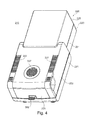
- FIG. 4 the inventive measuring device 210 is shown in the measuring position. Since the housing 220 is closed in the measuring position, most components are not visible.
- the housing 220 has a fixed housing part 221 and a movable housing part 222. In the measuring position, a substantially closed test chamber is formed by the stationary housing part 221 and the movable housing part 222.
- the movable housing part 222 has outlet openings 227, through which gases can escape from the test space located in the interior of the housing 220 into the ambient air.
- the vent openings 227 are arranged in the measuring position on the upper side of the movable housing part 222. Particularly advantageous is an arrangement of the discharge openings 227 above the, also in the interior of the housing 220 arranged means for heating 170 of the sample.
- FIG. 5 the meter 210 is off FIG. 4 shown in loading position.
- the movable housing part 222 was brought from the measuring position by a translational movement in the loading position.
- the movable housing part 222 is connected by a translation guide 224 with the fixed housing part 221.
- the translation guide 224 has two legs arranged substantially parallel to one another, the orientation of which is used to define the translation of the movable housing part 222.
- the fixed housing part 221 is elongated.
- the weighing device is largely enclosed by the stationary housing part 221. Only one connected to the weighing device test receptacle 260 projects laterally out of the stationary housing part 221 out. On this test recording 260 differently configured containers such as Probeschalen, crucibles and the like can hang more.
- the fixed housing part 221 has an area which is arranged on the user facing away side of the sample holder 260. In this area, the weighing device is advantageously arranged. In loading position, the movable housing part 222 is above the fixed one Housing part 221, ideally above the side of the sample holder 260 arranged area arranged.
- the movable temperature sensor 280 is disposed on a movably mounted lance 281.
- the lance 281 is as in the schematic representation of FIGS. 3a and 3b has been described, attached by means of a pivot bearing on the stationary housing part.
- the axis of the pivot bearing also extends horizontally and the lance 281 is biased by a spring force in the measuring position.
- the temperature sensor 280 is arranged between the means for heating the sample 270 and the sample receptacle 260.
- the temperature sensor 280 and the lance 281 are arranged laterally and above the sample receptacle 260. In this way, the measuring device 210 can be charged with a sample without the user being hindered by the temperature sensor 280.
- the means for heating the sample 270 is arranged in the movable housing part 222.
- the means for heating the sample 270 becomes hot and thereby heats the sample arranged below on the sample receiver 260.
- electricity or electricity is needed.
- the stationary housing part 221 has a power connection 288, which is arranged on the rear side of the measuring device 210.
- the movable housing part 222 has no power connection. The current must therefore be transported from the fixed housing part 221 to the movable housing part 222. This is done by means of an electrical contact means.
- This electrical contact means has a first part 286 and a second part 287.
- the first part 286 of the electrical contact means is connected to the movable housing part 222 and the second part of the electrical contact means to the fixed housing part 221.
- the two parts of the electrical contact means 286, 287 are arranged such that in the measuring position, an electrical contact is present and the means for heating the sample 270 is supplied with power. In the loading position there is no contact via the electrical contact means 286, 287.
- the electrical contact is automatically ensured by the movement of the movable housing part 222.
- a rotatable, concentric connector as used in kettles, has proven to be an electrical contact means.
- the rotatable, concentric connector is particularly robust and provides reliable one electrical contact.
- other embodiments are conceivable. In particular male-female connections are well suited.
- an inner wind guard 265, 274 can be arranged inside the test chamber around the sample receptacle 260.
- This inner draft shield 265, 274 is preferably adapted to the outer shape of the sample cup and / or the outer shape of the means for heating the sample 270. Since usually round sample dishes are used, it is advisable to use an inner draft shield 265, 274 with a round outer shape.
- the inner draft shield may include an upper portion 274 and a lower portion 265.
- the upper part 274 is arranged on the movable housing part 222.
- a cylindrical interior is bounded, which is open for sample receiving. In this cylindrical interior, the means for heating the sample 270 is arranged.
- the upper inner draft shield can have a cylindrical surface. It is advantageous if the cylindrical surface above the sample receptacle is limited at least partially by means of area, preferably a cylinder base area. This surface is preferably arranged above the means for heating the sample 270. The side facing the means for heating the sample 270 is ideally heat-reflecting. As a result, part of the heat generated is reflected at the inner draft shield and is used to heat the arranged on the sample holder 160 sample.
- the surface may also have openings. As a result, gases can escape from the test chamber through the openings described and openings 227 in the housing 220 in the ambient air. However, it is also possible that the surface has no openings.
- the lower part of the inner draft shield 265 is arranged on the stationary housing part 221. Through the lower part of the inner draft shield 265, a cylindrical interior is formed, which is open to the means for heating the sample 270. In this cylindrical interior, the sample holder 260 is arranged.
- the interior of the upper inner draft shield 274 and the interior of the lower inner draft shield 265 form an interior in the measuring position, in which the means for heating the sample 270 and the sample receptacle 260 are arranged.
- Both the upper and the lower part of the inner draft shield 265, 274 may be made of one or more parts.
- a sample cup holder 266 may be used to introduce a sample cup into the test room.
- This sample cup holder 266 has a handle 267 and bearing surfaces 268 for the sample cup. During transport, the edges of the sample cup lie on the support surfaces 268. During the measurement, the sample cup lies only on the sample holder 260. The sample cup holder 266 does not touch the sample cup thereby. In particular, the weight of the sample cup holder 266 is not detected by the weighing device.
- FIG. 6 is the inventive meter 210 from FIG. 4 respectively.
- FIG. 5 shown in maintenance position.
- a part of the movable housing part 222 has been pivoted about a substantially horizontally oriented pivot axis 225 from the loading position to the maintenance position.
- the means for heating the sample 270 is disposed in the pivotable part of the movable housing part 222 and is pivoted together with the pivotable part of the movable housing part 222 when assuming the maintenance position.
- the parts arranged in the movable housing part 222 are easily accessible for maintenance purposes.
- the means for heating the sample 270 is arranged in the upper housing part 222.
- the means for heating the sample 270 is protected by a protective glass 272 during the measuring process.
- the upper part of the inner draft shield 274 is arranged.
- the protective glass 272 and the inner draft shield 274 is in FIG. 7 the Meter 220 with partially removed upper part of the inner draft shield 274 and in FIG. 8 the movable housing part 222 without protective glass 272 shown.
- a reflective surface is arranged which serves to reflect the heat radiation from the means for heating the sample 270 to the sample receptacle 260.
- the reflection may also be achieved by a suitable reflective material of the cylinder base surface or a reflective coating of the cylinder base surface.
- a substantially circular aperture 273 serves to concentrate the heat rays generated by the means for heating the sample 270.
- the means for heating the sample 270 is aligned in the vertical direction.
- At least part of the upper inner draft shield 274 is fastened to the movable housing part 222 by means of a plug connection, wherein the plug connection is oriented substantially vertically in the maintenance position.
- the protective glass 272 is clamped between the aperture 273 and a portion of the upper inner draft shield 274. To remove the protective glass only a portion of the inner draft shield 274 must be pulled out of the connector. Thereafter, the protective glass can be removed simply by pulling out, without the aid of tools.
- the simple removal of the protective glass 272 is particularly advantageous because in this way the dirt-prone protective glass 272 can be easily removed and cleaned.
- the protective glass 272 and / or a part of the upper part of the inner draft shield 274 can be removed from the movable housing part in a controlled direction by means of a guide rail 275.
- the guide rail 275 is oriented substantially vertically in the maintenance position.
- the removal of the protective glass 272 is additionally simplified by a maintenance opening 223.
- the maintenance opening 223 is an opening in the movable housing part 222, which is open only in the maintenance position, but not in the measuring position or loading position. This prevents unintentional contact with the means for heating the sample. The risk of burns can be reduced.
- the maintenance opening is realized by means of a two-part movable housing part. The two parts of the movable housing part are included designed such that when taking the maintenance position, a part of the movable housing part is not pivoted. This non-pivoted part releases the maintenance opening in the pivoted part of the movable housing part.
- the width of the maintenance opening 223 is advantageously equal to or greater than the width of the protective glass 272. In this way, the protective glass can be easily removed.
- the maintenance opening 223 is arranged orthogonal to the plugging direction of the upper part of the inner draft shield 274 or in the extension of the guide rail 275. By this arrangement it is ensured that the protective glass 272 can be easily pulled out of the maintenance opening 223.
- the upper part of the inner draft shield 274 may be multi-part.
- the maintenance opening 223 facing part is advantageously removable without tools.
- the maintenance opening 223 must be wider than the upper part of the inner draft shield 274.
- the means for heating the sample 270 may be attached to the movable housing part 222 in various ways. It is possible, for example, to fix the means for heating 270 by means of a screw or a plug connection on the movable housing part 222. If a plug connection is used, the heating means 270 can simply be pulled out for maintenance purposes. Ideally, this connector would be designed such that the plugging direction is oriented substantially orthogonal to the maintenance opening 223.
- the means for heating the sample 270, the aperture 273, the protective glass 272 and the upper part of the inner draft shield 274 have white openings through which vapors and / or volatile substances escaping from a sample are discharged via these openings and through discharge openings 227 into the ambient air can.
- the openings are therefore arranged so that a direct withdrawal of escaping from the sample gases is ensured.
- the protective glass 272 is easily removable, it can be cleaned more easily and quickly by the user or service technician. Ideally, the protective glass 272 is such that it can be cleaned in a conventional dishwasher without being damaged.
- the presented embodiments show partly schematically illustrated measuring devices for gravimetric moisture determination with different properties and features.
- the various properties and features have been presented for better clarity in various embodiments, wherein it is also possible to implement individual, several or all shown features and properties in a meter.
Abstract
Description
- Die vorliegende Erfindung bezieht sich auf ein Messgerät zur gravimetrischen Feuchtigkeitsbestimmung.
- Zur Bestimmung des Feuchtigkeitsgehaltes einer Probe wird diese getrocknet und das Gewicht vor und nach dem Trocknungsvorgang manuell bestimmt. Durch die umfangreichen Arbeitsabläufe, die mit dieser Methode verbunden sind, ist diese sehr teuer und anfällig für Fehler.
- Gegebenenfalls kann der Gewichtsverlust auch während des Trocknungsvorganges gemessen werden. Dabei nimmt bei einer bekannten Probe in Abhängigkeit der Temperatur, der Trocknungszeit und den Prüfraumbedingungen deren Gewichtswert ab, welcher einer Gewicht- Zeit- Kurve folgt, die sich asymptotisch dem Trockengewicht der Probe annähert. Die Kurve wird für die jeweilige Probe durch Vergleichsversuche ermittelt und kann in einer Näherungsformel mathematisch ausgedrückt werden. Aufgrund der zur Verfügung stehenden elektronischen Mittel kann ein entsprechend ausgerüstetes Messgerät zur gravimetrischen Feuchtigkeitsbestimmung den Feuchtigkeitsgehalt einer Probe anhand der gemessen Kurvenparameter und der Trocknungszeit errechnen und auf einer Anzeigeeinheit anzeigen. Durch diese Methode muss das zu trocknende Gut nicht mehr vollständig durchgetrocknet sein, es genügt die Ermittlung der Koordinaten zweier Erfassungspunkte im Gewicht-Zeitdiagramm.
- Wie bereits eingangs erwähnt, verändert sich das Gewicht einer Probe im Wesentlichen in Abhängigkeit von der Temperatur, der Trocknungszeit und den Prüfraumbedingungen. Vor allem die hohen Anforderungen an den Prüfraum beschränken die auf dem Markt erhältlichen Geräte in ihrer Genauigkeit.
- Als Prüfraum wird ein durch das Gehäuse des Messgerätes umschlossener, zwecks Einführung beziehungsweise Entfernung einer Probe öffenbarer Raum bezeichnet. Im Inneren des Prüfraums sind zudem eine Probeaufnahme und ein Mittel zur Erwärmung der Probe angeordnet. Die Probeaufnahme ist mit einem gravimetrischen Messgerät verbunden.
- Üblicherweise wird eine dünne Schicht der Probe auf eine ebene Probeaufnahme, beispielsweise eine Probeschale aufgebracht. Die Schale wird im Messgerät zur gravimetrischen Feuchtigkeitsbestimmung in ihrer flächigen Ausdehnung vorzugsweise horizontal und parallel zur flächigen Ausdehnung des Mittels zur Erwärmung der Probe angeordnet, um eine gleichmässige Erwärmung der Probe zu ermöglichen.
- Als Mittel zur Erwärmung der Probe werden verschiedene Strahlungsquellen wie Heizstrahler, Mikrowellengeneratoren, Halogen- und Quarzlampen verwendet. Durch Versuche konnte festgestellt werden, dass eine der Hauptursachen einer ungenauen Messwerterfassung bei bestehenden Messgeräten zur gravimetrischen Feuchtigkeitsbestimmung die Art der verwendeten Strahlungsquellen und deren Anordnung im Prüfraum ist.
- Ein Messgerät zur gravimetrischen Feuchtigkeitsbestimmung der genannten Gattung ist aus der europäischen Patentschrift
EP 0 611 956 B1 bekannt. Bei diesem Gerät erfolgt die Beschickung der Waagschale ausserhalb des Messgerätes zur gravimetrischen Feuchtigkeitsbestimmung. Dazu wird die Waage auf einem schubladenförmigen Auszug aus dem Messgerätgehäuse herausgefahren. Als Strahlungsquelle wird eine ringförmige Halogenlampe eingesetzt, welche im Betriebszustand oberhalb der Probeaufnahme angeordnet ist. AusEP 1850 110 A1 sind weitere Ausführungsformen bekannt. Es wird beispielsweise ein Messgerät offenbart das zur Beschickung geöffnet wird, indem ein Teil des Gehäuses in horizontaler Richtung verschwenkt wird. In einer weiteren Ausführungsform wird ein Teil des Gehäuses in vertikaler Richtung verschwenkt. Auch die inUS 7851 712 B2 offenbarten Messgeräte werden durch Verschwenkung in vertikaler Richtung eines Gehäuseteils zur Beschickung geöffnet. - Zum Schutz des Mittels zur Erwärmung der Probe kann zwischen der Probe und dem Mittel zur Erwärmung der Probe ein Schutzglas angeordnet sein. Dieses Schutzglas ist verschmutzungsanfällig. Bei den bekannten Messgeräten ist das Schutzglas nur schwer zugänglich und wird deshalb nur selten gereinigt, was zu Verfälschungen des Messresultates führen kann.
- Aufgabe ist es daher, ein Messgerät zur gravimetrischen Feuchtigkeitsbestimmung zur Verfügung zu stellen, welches auf einfache Weise gereinigt werden kann.
- Diese Aufgabe wird durch das erfindungsgemässe Messgerät zur gravimetrischen Feuchtigkeitsbestimmung gemäss Anspruch 1 und dessen abhängigen Ansprüchen gelöst.
- Das erfindungsgemässe Messgerät zur gravimetrischen Feuchtigkeitsbestimmung weist ein Gehäuse und eine im Gehäuse angeordnete Wägevorrichtung auf. Dabei weist die Wägevorrichtung eine Lastaufnahme, auf die eine Probe auflegbar ist, auf. Das Gehäuse weist einen feststehenden Gehäuseteil und einen beweglicher Gehäuseteil auf. Der bewegliche Gehäuseteil kann eine Messposition und eine Wartungsposition einnehmen, wobei der feststehende Gehäuseteil und der beweglichen Gehäuseteil in Messposition einen im Wesentlichen abgeschlossenen Prüfraum um die Lastaufnahme bildet und im Prüfraum ein Mittel zur Erwärmung einer auf der Lastaufnahme auflegbaren Probe angeordnet ist. In der Wartungsposition sind der feststehende Gehäuseteil und der bewegliche Gehäuseteil derart voneinander beabstandet, dass das Mittel zur Erwärmung für Wartungszwecke zugänglich ist. In Messposition ist zwischen dem Mittel zur Erwärmung der Probe und der Probe ein Schutzglas angeordnet. Erfindungsgemäss ist das Schutzglas am beweglichen Gehäuseteil angeordnet und in Wartungsposition werkzeuglos entfernbar. Auf diese Weise kann das Schutzglas einfach entfernt und gereinigt werden. Der Benutzer bzw. der Servicetechniker benötigen weniger Zeit für diesen Vorgang und werden ihn deshalb öfter durchführen.
- In diesem Zusammenhang wird unter Gehäuseteil das Gehäuse mit den darin beziehungsweise daran angeordneten Geräteelementen verstanden. Typischerweise ist am beweglichen Gehäuseteil das Mittel zur Erwärmung der Probe und im feststehenden Gehäuseteil die Wägevorrichtung, die Probenaufnahme und das Elektronikmodul angeordnet.
- Das erfindungsgemässe Messgerät kann eine Beschickungsposition einnehmen, wobei in Beschickungsposition der feststehende Gehäuseteil und der bewegliche Gehäuseteil derart voneinander beabstandet sind, dass eine Probe auf die Lastaufnahme aufbringbar ist. Mittels eines Verschiebungsmittels ist der bewegliche Gehäuseteil von der Messposition in die Beschickungsposition verschiebbar. Sowohl in Messposition, Beschickungsposition als auch Wartungsposition ist der bewegliche Gehäuseteil oberhalb des feststehenden Gehäuseteils angeordnet.
- Vorteilhafterweise ist das Mittel zur Erwärmung und somit auch das Schutzglas in der Wartungsposition im Wesentlichen vertikal ausgerichtet. Dadurch ist das Mittel zur Erwärmung dem Benutzer zugewandt und leichter zugänglich.
- In einer Ausführungsform ist das Schutzglas mittels einer werkzeuglos lösbaren Verbindung mit dem beweglichen Gehäuseteil verbunden. Zu Wartungszwecken kann das Schutzglas einfach aus dem beweglichen Gehäuseteil gezogen werden.
- In einer möglichen Ausführungsform ist das Schutzglas mittels ebenfalls werkzeuglos entfernbarer Bauteilen am beweglichen Gehäuseteil fixiert. Diese Bauteile können beispielsweise das Schutzglas in einer vordefinierten Position festklemmen. Es ist auch möglich, dass das Schutzglas und die Bauteile durch eine Feder-Nut Verbindung miteinander verbunden sind. Die Feder-Nut Verbindung kann manuell ohne zu Hilfenahme von Werkzeugen gelöst werden.
- Auch der Einsatz von Halterungen ist möglich. Die Halterungen können auch der Positionierung des Schutzglases dienen. In einer möglichen Ausführungsform ist das Schutzglas zwischen einer oberen Halterung und einer unteren Halterung positionierbar und zumindest eine der Halterungen ist werkzeuglos entfernbar. Die obere Halterung ist dabei an der dem Mittel zur Erwärmung der Probe zugewandten Seite angeordnet. Die untere Halterung ist an der Probenaufnahme zugewandten Seite angeordnet. Das Schutzglas ist zwischen der oberen und unteren Halterung positioniert. Entweder die obere oder die untere Halterung ist werkzeuglos entfernbar. Um das Schutzglas zu entfernen muss die werkzeuglos entfernbare Halterung entfernt werden. Anschliessend kann das Schutzglas entfernt werden ohne dass Werkzeug benötigt wird.
- Sowohl das Schutzglas als auch die obere und untere Halterung können mittels am beweglichen Gehäuseteil angeordneter Führungsschienen in das bewegliche Gehäuseteil eingeführt werden und dort positioniert bzw. gehalten werden. Die Führungsschienen sind in Messposition und/oder Beschickungsposition im Wesentlichen horizontal ausgerichtet. In Wartungsposition sind die Führungsschienen im Wesentlichen vertikal ausgerichtet.
- Die werkzeuglos entfernbare Halterung und/oder das Schutzglas ist mittels mindestens einer Führungsschiene in einer kontrollierten Richtung aus dem beweglichen Gehäuseteil entfernbar. Die Führungsschiene erleichtert dem Benutzer das Entfernen bzw. das Positionieren des Schutzglases und/oder der werkzeuglos enfernbaren Halterung.
- In Wartungsposition ist die Führungsschiene vertikal ausgerichtet. Dadurch wird es dem Benutzer ermöglicht das Schutzglas und/oder die werkzeuglos entfernbare Halterung nach oben aus dem beweglichen Gehäuseteil zu entfernen. Ausserdem kann der Benutzer direkt auf die Halterung, das Schutzglas und das Mittel zur Erwärmung der Probe schauen. Diese Anordnung vereinfacht es dem Benutzer das Schutzglas zu entfernen.
- Das Entfernen des Schutzglases und der Halterung wird zusätzlich durch eine Wartungsöffnung im beweglichen Gehäuseteil erleichtert. Durch die Wartungsöffnung kann das Schutzglas und/oder eine Halterung entfernt werden. Die Wartungsöffnung ist idealerweise in der Verlängerung der Führungsschiene angeordnet. Durch diese Anordnung wird es ermöglicht das Schutzglas und/oder die Halterung mittels der Führungsschiene geführt durch die Wartungsöffnung aus dem beweglichen Gehäuseteil zu entfernen.
- Die Wartungsöffnung ist in Wartungsposition geöffnet. In Messposition und Beschickungsposition ist sie hingegen geschlossen. In Messposition und Beschickungsposition ist die Wartungsöffnung durch einen Teil des beweglichen Gehäuseteils verschlossen. Dadurch besteht beim Messen und Beschicken die Öffnung nicht. Es können beim Messen und Beschicken keine Verunreinigungen durch die Wartungsöffnung in das Messgerät eindringen.
- In einer bevorzugten Ausführungsform ist um das Mittel zur Erwärmung der Probe und das Schutzglas zumindest ein Teil eines Innenwindschutzes angeordnet. Ein Teil des Innenwindschutzes dient als obere Halterung zur Positionierung des Schutzglases. Es ist somit keine zusätzliche Halterung für das Schutzglas notwendig. Der Innenwindschutz ist am beweglichen Gehäuseteil angeordnet.
- Ausserdem weist das Messgerät eine Blende auf mittels der auf die Richtung der Wärmestrahlung auf die Probe Einfluss genommen werden kann. Diese Blende kann gleichzeitig als untere Halterung des Schutzglases dienen. Diese Blende ist am beweglichen Gehäuseteil angeordnet und ist werkzeuglos entfernbar.
- Das Mittel zur Erwärmung der Probe kann beispielsweise eine Heizplatte, eine Heizfolie, eine Breitband- Lichtquelle, eine monochromatische Lichtquelle, einen Heizstrahler, eine Heizschlange, ein Peltier-Element oder einen Mikrowellengenerator aufweisen.
- In einer vorteilhaften Ausführungsform weist das Messgerät ein elektrisches Kontaktmittel mit einem ersten Teil und einem zweiten Teil auf. Der erste Teil des elektrischen Kontaktmittels ist mit dem feststehenden Gehäuseteil und der zweite Teil des elektrischen Kontaktmittels mit dem beweglichen Gehäuseteil verbunden. Dabei besteht in Messposition über den ersten und zweiten Teil des elektrischen Kontaktmittels eine elektrische Verbindung und in Beschickungsposition ist die elektrische Verbindung zwischen dem ersten und dem zweiten Teil des elektrischen Kontaktmittels unterbrochen.
- Idealerweise ist nur der feststehende Gehäuseteil am Stromnetz angeschlossen und der bewegliche Gehäuseteil ist ausschliesslich über das elektrische Kontaktmittel am Stromnetz angeschlossen. Durch diese Anordnung wird sichergestellt, dass nur in Messposition am beweglichen Gehäuseteil Spannung anliegt. In Beschickungsposition und Wartungsposition liegt keine Spannung am beweglichen Gehäuseteil an. Dadurch wird das Mittel zur Erwärmung der Probe während der Beschickung und Wartung nicht mit Strom versorgt und die Verbrennungsgefahr für den Benutzer ist reduziert.
- Idealerweise ist die Wägevorrichtung im feststehenden Gehäuseteil angeordnet. In einer bevorzugten Ausführungsform ist die Wägevorrichtung in einem Wägeraum angeordnet und der Wägeraum und der Prüfraum sind durch mindestens eine vertikale Trennwand voneinander getrennt, wobei diese Trennwand mindestens eine Durchführung aufweist, durch die ein Verbindungsglied hindurchreicht, mit welchem die Wägevorrichtung mit der im Prüfraum angeordneten Probeaufnahme verbindbar ist.
- Einzelheiten des erfindungsgemässen Messgeräts ergeben sich anhand der Beschreibung des in den Zeichnungen dargestellten Ausführungsbeispiels. Es zeigen:
- Fig. 1
- einen Schnitt durch eine schematische Darstellung eines erfindungsgemässes Messgeräts in Messposition;
- Fig. 2
- einen Schnitt durch eine schematische Darstellung des Messgeräts aus
Figur 1 in Beschickungsposition; - Fig. 3a
- eine schematische Darstellung eines weiteren erfindungsgemässen Messgeräts mit einem Temperatursensor, der sich in Messposition befindet;
- Fig. 3b
- eine schematische Darstellung des in
Fig. 3a dargestellten Messgeräts wobei sich der Temperatursensor in Beschickungsposition befindet; - Fig. 4
- eine isometrische Darstellung des erfindungsgemässen Messgeräts in Messposition;
- Fig. 5
- das Messgerät aus
Figur 4 in Beschickungsposition; - Fig. 6
- das Messgerät aus
Figur 4 in Wartungsposition; - Fig. 7
- das Messgerät aus
Figur 6 in Wartungsposition mit teilweise entferntem Schutzglas und Windschutz und - Fig. 8
- der bewegliche Gehäuseteil des Messgeräts aus
Figur 7 in Wartungsposition ohne Schutzglas. - In
Figur 1 undFigur 2 ist eine schematische Darstellung eines erfindungsgemässen Messgeräts 10 im Schnitt dargestellt. InFigur 1 befindet sich das Messgerät 10 in Messposition und inFigur 2 in Beschickungsposition. Das Messgerät 10 weist ein Gehäuse 20 auf, in welchem ein Prüfraum 30 angeordnet ist. Das Gehäuse 20 ist in einen beweglichen Gehäuseteil 22 und in einen feststehenden Gehäuseteil 21 unterteilt. Bei Benutzung steht der feststehende Gehäuseteil 21 auf einer festen Unterlage. Der bewegliche Gehäuseteil 22 ist am feststehenden Gehäuseteil befestigt. Hinten, das heisst an der vom Benutzer abgewandten Seite des Prüfraumes 30 ist eine Wägevorrichtung 40 im feststehenden Gehäuseteil 21 angeordnet. Der bewegliche Gehäuseteil 22 ist mittels einer Translationsführung 24 am feststehenden Gehäuseteil 21 geführt. Die Translationsführung 24 ist derart ausgestaltet, dass bei der Bewegung des beweglichen Gehäuseteils 22 von der Messposition in die Beschickungsposition die Ausrichtung des beweglichen Gehäuseteils 22 im Wesentlichen konstant bleibt. D.h. der bewegliche Gehäuseteil 22 wird im Wesentlichen parallel zum feststehenden Gehäuseteil 21 verschoben. Im als Hohlkörper ausgestalteten feststehenden Gehäuseteil 21 sind eine Wägezelle 43 und mindestens ein Elektronikmodul 90 angeordnet, welche durch Übertragungsmittel 52 miteinander verbunden sind. Das Elektronikmodul 90 enthält mindestens ein nicht näher dargestelltes Signalverarbeitungsmodul, gegebenenfalls auch ein Steuerungsund/oder Regelungsmodul. Die Wägezelle 43 weist mindestens einen feststehenden Bereich 41 und einen Lastaufnahmebereich 42 auf. Bekannte Wägezellentypen sind beispielsweise mit Dehnungsmessstreifen bestückte elastische Verformungskörper, Wägezellen die nach dem Prinzip der elektromagnetischen Kraftkompensation arbeiten, Wägezellen mit Schwingsaiten, kapazitive Wägesensoren und dergleichen. Der feststehende Bereich 41 ist mit dem feststehenden Gehäuseteil 21 fest verbunden und am Lastaufnahmebereich 42 ist ein Verbindungsglied 47 angeordnet, welches eine Probeaufnahme 60 mit dem Lastaufnahmebereich 42 der Wägezelle 43 verbindet. Auf die Probeaufnahme 60 kann wie dargestellt eine Probeschale 61 mit einer Probe 62 aufgelegt werden. Sofern es die Ausgestaltung der Probeaufnahme 60 erlaubt, kann selbstverständlich die Probe 62 auch direkt auf die Probeaufnahme 60 aufgebracht werden. - Wie in
Figur 1 dargestellt, befindet sich das Messgerät 10 in Messstellung; das heisst, dass sich die Probeaufnahme 60 mit der aufgelegten Probeschale 61 im Prüfraum 30 befindet. Der feststehende Gehäuseteil 21 und der bewegliche Gehäuseteil 22 bilden einen im Wesentlichen abgeschlossenen Prüfraum 30 um die Probenaufnahme 60. Eine Mittel zur Erwärmung 70 ist im Wesentlichen parallel zur flächigen Ausdehnung der Probeaufnahme 60 angeordnet, um eine möglichst homogene Wärmeverteilung zumindest an der Oberfläche der Probe 62 zu erreichen. Es ist auch möglich unterhalb der Probeaufnahme 60 im Prüfraum 30 ein zusätzliches Mittel zur Erwärmung anzuordnen, wobei deren Strahlung von unten auf die Probe 62 einwirkt. Eine in ihrer flächigen Ausdehnung parallele Anordnung des Mittels zur Erwärmung 70 der Probeaufnahme 60 ist aber nicht zwingend erforderlich. Je nach Probe 62 und durchzuführender Messung kann auch ein schräg zur Probeaufnahme 60 angeordnetes Mittel zur Erwärmung 70 von Vorteil sein. - Damit die von der Probe 62 abgegebene Feuchtigkeit aus dem Prüfraum 30 entweichen kann, sind im Gehäuse 20 an geeigneter Stelle, vorzugsweise oberhalb des Mittels zur Erwärmung 70 im beweglichen Gehäuseteil 22, Abzugsöffnungen 27 angeordnet. Um eine ausreichende Luftzirkulation innerhalb des Prüfraumes 30 zu erzeugen, sind ferner an geeigneter Stelle Belüftungsöffnungen vorzusehen.
- In
Figur 1 befindet sich das Messgerät 10 in Messposition. Der feststehende Gehäuseteil 21 und der bewegliche Gehäuseteil 22 bilden einen im Wesentlichen abgeschlossenen Prüfraum 30. Dabei wird der Prüfraum 30 nach oben im Wesentlichen vom beweglichen Gehäuseteil 22 und nach unten im Wesentlichen vom feststehenden Gehäuseteil 21 begrenzt. Das Mittel zur Erwärmung 70 ist im beweglichen Gehäuseteil 22 angeordnet. Idealerweise ist das Mittel zur Erwärmung 70 über Steckverbindungen lösbar mechanisch mit dem beweglichen Gehäuseteil 22 verbunden. Dadurch kann das Mittel zur Erwärmung 70 zur Reinigung oder Reparatur ohne grossen Aufwand ausgebaut werden. Ferner können durch die Verwendung von Steckverbindungen der Anwender das Messgerät 10 verschiedene, in ihrer Funktionsweise unterschiedliche Mittel zur Erwärmung verwenden. Dadurch ist der Anwender in der Lage, auf die Probe 62 abgestimmte Prüfraumbedingungen zu schaffen. - Das Messgerät 10 weist ein Elektronikmodul 90 auf, das im feststehenden Gehäuseteil 21 angeordnet ist. Das Elektronikmodul 90 weist verschiedene Steuer-/Regelvorrichtungen auf. Unter anderem weist sie auch eine Steuer-/Regelvorrichtung 35 zur Steuerung und Regelung des Mittels zur Erwärmung 70 auf. Ein schematisch dargestellter Temperatursensor 80 erfasst die Temperatur der Probe 62 und liefert die zur Regelung des Mittels zur Erwärmung 70 notwendigen Informationen an die Steuer-/Regelvorrichtung 35. Die Steuer-/Regelvorrichtung 35 ist zudem mit der Wägevorrichtung 40 beziehungsweise mit dem Elektronikmodul 90 mittels mindestens eines Übertragungsmittels 52 verbunden. Das Übertragungsmittel 52 dient der Übermittlung von elektrischen und/oder elektronischen Signalen. Dadurch kann mittels des Elektronikmoduls 90 die Steuer-/Regelvorrichtungen 35 angesteuert werden. Das Messgerät 10 wird mittels eines Stromanschlusses 88 mit Strom versorgt. Der Stromanschluss 88 ist am feststehenden Gehäuseteil 21 angeordnet. Die Stromzufuhr erfolgt bevorzugterweise ausschliesslich über das feststehende Gehäuseteil 21. Der Benutzer bzw. Servicetechniker ist somit nicht der Gefahr ausgesetzt während der Wartung einen Stromschlag zu bekommen.
- Die Steuer-/Regelvorrichtung 35 und der Temperatursensor 80 sind mittels eines Übertragungsmittels 51 miteinander verbunden. Ausserdem sind die Steuer-/Regelvorrichtung 35 und das Mittel zur Erwärmung der Probe 70 mittels eines weiteren Übertragungsmittels 53 miteinander verbunden. Die Übertragungsmittel 51, 53 dienen der Übermittelung von elektrischen und elektronischen Signalen zwischen den jeweiligen Bauteilen. Während des Messvorgangs wird mittels des Temperatursensors 80 die Temperatur im Prüfraum 30 bestimmt. Das mittels des Temperatursensors 80 erzeugte Temperatursignal wird mittels des Übertragungsmittels 51 an die Steuer-/Regelvorrichtung 35 übermittelt. Das Temperatursignal ist ein Eingangssignal der Steuer-/Regelvorrichtung 35 mittels dessen das Mittel zur Erwärmung der Probe 70 gesteuert wird.
- Der Temperatursensor 80 ist in Messposition zwischen der Probenaufnahme 60 und dem Mittel zur Erwärmung der Probe 70 angeordnet. Durch diese Anordnung kann der für die Messung relevante Temperaturwert gemessen werden. Es besteht auch die Möglichkeit den Temperatursensor an einer anderen Stelle zu positionieren. Die dadurch erhaltenen Werte können jedoch die Erwärmung im Prüfraum weniger genau erfassen. Der Temperatursensor 80 ist auf einer Lanze 81 angeordnet, die am feststehenden Gehäuseteil 21 befestigt ist. Die Lanze 81 ist im Wesentlichen starr und weist ein erstes und ein zweites Ende auf. Am ersten Ende ist der Temperatursensor 80 angeordnet, das zweite Ende ist mit dem feststehenden Gehäuseteil 21 verbunden. Dadurch dass das zweite Ende mit dem feststehenden Gehäuseteil 21 verbunden ist, ist für den Betrieb des Temperatursensors 80 keine elektrische und/oder elektronische Verbindung vom feststehenden Gehäuseteil 21 zum beweglichen Gehäuseteil 22 erforderlich.
- Das Übertragungsmittel 51 ist an oder in der Lanze 81 angeordnet. Über ein Drehlager 82 kann die Lanze 81 verdreht werden. Das Drehlager 82 ist am zweiten Ende der Lanze 81 angeordnet. Das Drehlager 82 weist eine Drehachse 83 auf, wobei die Achse des Drehlagers 83 im Wesentlichen horizontal ausgerichtet ist.
- Die Lanze 81 und das Drehlager 83 sind derart angeordnet dass der Temperatursensor 80 beim Wechsel von der Messposition in die Beschickungsposition auf einer kreisförmigen Bahn in einer vertikalen Ebene geführt wird. Es ist auch möglich die kreisförmige Bahn in einer anderen Ebene anzuordnen. So ist es beispielsweise möglich die Achse des Drehlagers im Wesentlichen vertikal auszurichten, wodurch der Temperatursensor 80 beim Wechsel von Messposition in Beschickungsposition in einer kreisförmigen Bahn in einer horizontalen Ebene geführt wird.
- Die Lanze 81 ist in Messposition mittels der Federkraft eines Federelements 84 vorgespannt. Wird der bewegliche Gehäuseteil 22 von der Messposition in die Beschickungsposition gebracht, so wird die Lanze 81 mittels der Federkraft des vorgespannten Federelements 84 von der Probenaufnahme 60 wegbewegt. Der Temperatursensor 80 und die Lanze 81 behindern in Beschickungsposition nicht den Zugriff auf die Probenaufnahme 60 und die Beschickung des Messgeräts vereinfacht sich. Das Federelement 84 weist idealerweise eine drehmomentbelastete Feder auf, wobei die Achse des Drehmoment mit der Achse des Drehlagers 83 übereinstimmt. Es sind natürlich auch andere Federelemente, wie beispielsweise druckbelastete Federelemente einsetzbar. Dabei muss das Federelement derart angeordnet sein, dass es in Messposition gespannt ist und in Beschickungsposition entspannt bzw. weniger gespannt ist.
- Da das Mittel zur Erwärmung der Probe 70 im beweglichen Gehäuseteil 22 und die Steuer- und Regelvorrichtung 35 im feststehenden Gehäuseteil 21 angeordnet ist, muss das Übertragungsmittel 53 elektrische und/oder elektronische Signale vom feststehenden Gehäuseteil 22 in den beweglichen Gehäuseteil 21 übertragen. Dies könnte beispielsweise durch ein flexibles Kabel erfolgen. Durch die Bewegung des beweglichen Gehäuseteils 21 wäre dieses Kabel Biegebelastungen ausgesetzt und wäre daher verschleissanfällig.
- Durch ein elektrisches Kontaktmittel mit einem ersten Teil 86 und einem zweiten Teil 87, wobei der erste Teil 86 mit dem beweglichen Gehäuseteil 22 und der zweite Teil mit dem feststehenden Gehäuseteil 21 fest verbunden ist, kann dieses Problem umgangen werden. Dazu ist der erste und der zweite Teil des elektrischen Kontaktmittels 86, 87 derart angeordnet, dass in Messposition über den ersten und zweiten Teil 86, 87 eine elektrische Verbindung besteht und in Beschickungsposition die elektrische Verbindung unterbrochen ist. Ein wesentlicher Vorteil dieser Anordnung besteht darin, dass das Mittel zur Erwärmung der Probe 70 in Beschickungsposition nicht mit Elektrizität versorgt wird. Idealerweise ist die Elektronik zur Steuerung ausschliesslich im feststehenden Gehäuseteil 22 angeordnet. Die Steuerung des Mittels zur Erwärmung der Probe 70 erfolgt ausschliesslich über das erste und zweite elektrische Kontaktmittel 86, 87. Es ist somit kein Anschluss zum Transport von Steuersignalen in den beweglichen Gehäuseteil 21 notwendig. Dies ist ein weiterer Grund für die Anordnung des Temperatursensors 80 am feststehenden Gehäuseteil 21. Wäre der Temperatursensor 80 am beweglichen Gehäuseteil 22 angeordnet, wäre ein Transfer von Signalen vom feststehenden Gehäuseteil 21 in den beweglichen Gehäuseteil 22 notwendig. Ein weiterer Vorteil des erfindungsgemässen Messgeräts 10 besteht darin, dass auch in Beschickungsposition die Temperatur mittels des Temperatursensors 80 gemessen und erfasst werden kann. Auf diese Weise kann beispielsweise die Umgebungstemperatur während des Beschickens gemessen werden.
- Das elektrische Kontaktmittel 86, 87 weist eine Steckverbindung auf. Dabei ist einer der beiden Teile des elektrischen Kontaktmittels 86, 87 als Stecker ausgebildet und der andere Teil als eine mit dem Stecker zusammenwirkende Buchse ausgebildet. Die Steckrichtung der Steckerverbindung verläuft im Wesentlichen in vertikaler Richtung.
- In
Figur 2 ist das Messgerät 10 ausFigur 1 in Beschickungsposition dargestellt. Mittels einer Translationsführung 24 kann der bewegliche Gehäuseteil 22 vom feststehenden Gehäuseteil 21 wegbewegt werden, wodurch das Messgerät 10 von der Messposition in die Beschickungsposition übergeführt wird. Bei der dabei ausgeführten Bewegung erfährt der bewegliche Gehäuseteil 22 eine im Wesentlichen rein translatorische Bewegung. In Beschickungsposition ist der bewegliche Gehäuseteil 22 oberhalb des feststehenden Gehäuseteils 21 und oberhalb der Wägevorrichtung 40 angeordnet. Das Mittel zur Erwärmung der Probe 70 ist in dieser Position zwischen dem beweglichen Gehäuseteil 22 und dem feststehenden Gehäuseteil 21 angeordnet. - Dadurch wird ein unbeabsichtigtes Berühren des unter Umständen heissen Mittels zur Erwärmung der Probe 70 verhindert.
- Der Temperatursensor 80 wird bei Einnahme der Beschickungsposition nach oben und seitlich von der Probenaufnahme 60 wegbewegt. Der Temperatursensor 80 behindert somit das Beschicken der Probenaufnahme 60 nicht.
- Das elektrische Kontaktmittel 86, 87 ist in der Beschickungsposition unterbrochen. Es fliesst keine Elektrizität vom feststehenden Gehäuseteil 21 in der bewegliche Gehäuseteil 22. Da der bewegliche Gehäuseteil 22 über keinen Stromanschluss verfügt, liegt in Beschickungsposition kein Strom am beweglichen Gehäuseteil 22 an.
- In den
Figuren 3a und 3b ist ein weiteres erfindungsgemässes Messgerät 110 stark schematisiert dargestellt.Figur 3a zeigt die Messvorrichtung 110 in Messposition undFig. 3b zeigt das inFig. 3a dargestellte Messgerät 110 in Beschickungsposition. - Das Messgerät 110 weist ein Gehäuse 120 mit einem feststehenden Gehäuseteil 121 und einem beweglichen Gehäuseteil 122 auf.
- In Messposition wird vom feststehenden Gehäuseteil 121 und vom beweglichen Gehäuseteil 122 ein im Wesentlichen abgeschlossener Prüfraum 130 gebildet. In diesem Prüfraum 130 ist die Probenaufnahme 160 angeordnet. Oberhalb der Probenaufnahme 160 ist ein Mittel zur Erwärmung der Probe 170 angeordnet. Das Mittel zur Erwärmung der Probe 170 ist fest mit dem beweglichen Gehäuseteil 122 verbunden. Ein Temperatursensor 180 ist auf einer Lanze 181 angeordnet. Die Lanze 181 weist ein erstes und ein zweites Ende auf, wobei am ersten Ende der Temperatursensor 180 befestigt ist und das zweite Ende beweglich mit dem feststehenden Gehäuseteil 121 verbunden ist. In Messposition ist der Temperatursensor 180 oberhalb der Lastaufnahme 160 und unterhalb des Mittels zur Erwärmung der Probe 170 angeordnet. In Beschickungsposition ist der Temperatursensor 180 im Wesentlichen seitlich der Laustaufnahme 160 angeordnet. Dies wird dadurch erreicht indem die Lanze 181 starr ist und mittels eines Drehlagers 182 am feststehenden Gehäuseteil 121 befestigt ist. Idealerweise ist die Achse 183 des Drehlagers 182 in horizontaler Richtung ausgerichtet. Die Lanze 181 kann in Messposition mittels der Federkraft eines Federelements vorgespannt sein. Wird das bewegliche Gehäuseteil 122 von der Messposition in Beschickungsposition gebracht, wird die Lanze 181 mittels der Federkraft des Federelements auf einer Kreisbahn nach oben und seitlich bewegt. Bevorzugterweise ist das Federelement in Messposition durch das bewegliche Gehäuseteil 122 vorgespannt.
- Um möglichst stabile Messergebnisse erhalten zu können, kann im Innern des Prüfraums ein Innenwindschutz angeordnet sein (siehe
Figuren 6 - 8 ). Dieser Innenwindschutz ist um die Probenaufnahme 160 und das Mittel zur Erwärmung der Probe 170 angeordnet und bildet einen nahezu geschlossenen Raum. Der Innenwindschutz kann einen oberen Teil 174 und einen unteren Teil 165 aufweisen. Der obere Teil 174 ist am beweglichen Gehäuseteil 122 angeordnet. Durch den oberen Teil des Innenwindschutzes 174 wird ein zylinderförmiger Innenraum gebildet, der zur Probenaufnahme geöffnet ist. In diesem zylinderförmigen Innenraum ist das Mittel zur Erwärmung der Probe angeordnet. Der obere Innenwindschutz kann nur aus einer Zylinderfläche bestehen. Es ist jedoch vorteilhaft, wenn am oberen Ende eine in Messposition und Beschickungsposition horizontal ausgerichtete Fläche angeordnet ist. Diese Fläche ist bevorzugterweise oberhalb des Mittels zur Erwärmung der Probe 170 angeordnet. Die dem Mittel zur Erwärmung der Probe 170 zugewandte Seite, ist idealerweise hitzereflektierend. Dadurch wird ein Teil der erzeugten Wärme am Innenwindschutz reflektiert und wird zur Erwärmung der auf der Probenaufnahme 160 angeordneten Probe verwendet. Der untere Teil des Innenwindschutzes 165 ist am feststehenden Gehäuseteil 121 angeordnet. Durch den unteren Teil des Innenwindschutzes 165 wird ein zylinderförmiger Innenraum gebildet, der zum Mittel zur Erwärmung der Probe 170 hin offen ist. In diesem zylinderförmigen Innenraum ist die Probenaufnahme 160 angeordnet. Der Innenraum des oberen Innenwindschutzes 174 und der Innenraum des unteren Innenwindschutzes 165 bilden in Messposition einen Innenraum, in dem das Mittel zur Erwärmung der Probe 170 und die Probenaufnahme 160 angeordnet sind. Sowohl der obere als auch der untere Teil des Innenwindschutzes 165, 174 können aus einem Teil oder aus mehreren Teilen gefertigt sein. - In den
Figuren 4 ,5 ,6 ,7 und8 ist eine Ausführungsform des erfindungsgemässen Messgeräts 210 in verschiedenen Positionen dargestellt. Dieses Messgerät 210 weist sämtliche Bauteile auf, die bereits bei der Beschreibung der schematischen Ausführungsform ausFigur 1 und2 beschrieben wurden. - In
Figur 4 ist das erfindungsgemässe Messgerät 210 in Messposition dargestellt. Da das Gehäuse 220 in Messposition geschlossen ist, sind die meisten Bauteile nicht ersichtlich. Das Gehäuse 220 weist einen feststehenden Gehäuseteil 221 und einen beweglichen Gehäuseteil 222 auf. In Messposition wird vom feststehenden Gehäuseteil 221 und vom beweglichen Gehäuseteil 222 ein im Wesentlichen abgeschlossener Prüfraum gebildet. Der bewegliche Gehäuseteil 222 weist Abzugsöffnungen 227 auf, durch die Gase aus dem im Innern des Gehäuses 220 liegenden Prüfraum in die Umgebungsluft entweichen können. Vorteilhafterweise sind die Abzugsöffnungen 227 in Messposition auf der Oberseite des beweglichen Gehäuseteils 222 angeordnet. Besonders vorteilhaft ist eine Anordnung der Abzugsöffnungen 227 über dem, ebenfalls im Innern des Gehäuses 220 angeordneten, Mittel zur Erwärmung 170 der Probe. - In
Figur 5 ist das Messgerät 210 ausFigur 4 in Beschickungsposition dargestellt. Der bewegliche Gehäuseteil 222 wurde aus der Messposition durch eine translatorische Bewegung in die Beschickungsposition gebracht. Um diese translatorische Bewegung ausführen zu können, ist der bewegliche Gehäuseteil 222 durch eine Translationsführung 224 mit dem feststehenden Gehäuseteil 221 verbunden ist. Die Translationsführung 224 weist zwei im Wesentlichen parallel zueinander angeordnete Schenkel auf, durch deren Ausrichtung die Richtung der Translation des beweglichen Gehäuseteils 222 definiert ist. - Der feststehende Gehäuseteil 221 ist länglich ausgebildet. Die Wägevorrichtung ist vom feststehenden Gehäuseteil 221 weitgehend umschlossen. Einzig eine mit der Wägevorrichtung verbundene Probeaufnahme 260 ragt seitlich aus dem feststehenden Gehäuseteil 221 heraus. Auf dieser Probeaufnahme 260 lassen sich verschieden ausgestaltete Behältnisse wie Probeschalen, Tiegel und dergleichen mehr auflegen. Der feststehende Gehäuseteil 221 weist einen Bereich auf, der an der benutzerabgewandten Seite der Probenaufnahme 260 angeordnet ist. In diesem Bereich ist vorteilhafterweise die Wägevorrichtung angeordnet. In Beschickungsposition ist der bewegliche Gehäuseteil 222 oberhalb des feststehenden Gehäuseteils 221, idealerweise oberhalb des seitlich von der Probenaufnahme 260 angeordneten Bereichs, angeordnet.
- Der bewegliche Temperatursensor 280 ist, auf einer beweglich gelagerten Lanze 281 angeordnet. Die Lanze 281 ist wie in der schematischen Darstellung der
Figuren 3a und 3b beschrieben wurde, mittels eines Drehlagers am feststehenden Gehäuseteil befestigt. Die Achse des Drehlagers verläuft ebenfalls horizontal und die Lanze 281 ist auch mittels einer Federkraft in Messposition vorgespannt. In Messposition ist der Temperatursensor 280 zwischen dem Mittel zur Erwärmung der Probe 270 und der Probenaufnahme 260 angeordnet. In Beschickungsposition ist der Temperatursensor 280 und die Lanze 281 seitlich und oberhalb der Probenaufnahme 260 angeordnet. Auf diese Weise kann das Messgerät 210 mit einer Probe beschickt werden, ohne dass der Benutzer dabei durch den Temperatursensor 280 behindert wird. - Das Mittel zur Erwärmung der Probe 270 ist im beweglichen Gehäuseteil 222 angeordnet. Während der Messung wird das Mittel zur Erwärmung der Probe 270 heiss und erwärmt dadurch die unterhalb auf der Probenaufnahme 260 angeordnete Probe. Für die Erwärmung wird Elektrizität bzw. Strom benötigt. Dazu verfügt der feststehende Gehäuseteil 221 über einen Stromanschluss 288, der auf der Rückseite des Messgeräts 210 angeordnet ist. Der bewegliche Gehäuseteil 222 verfügt über keinen Stromanschluss. Der Strom muss deshalb vom feststehenden Gehäuseteil 221 zum beweglichen Gehäuseteil 222 transportiert werden. Dies geschieht Mittels eines elektrischen Kontaktmittels. Dieses elektrische Kontaktmittel weist einen ersten Teil 286 und einen zweiten Teil 287 auf. Der erste Teil 286 des elektrischen Kontaktmittels ist mit dem beweglichen Gehäuseteil 222 und der zweite Teil des elektrischen Kontaktmittels mit dem feststehenden Gehäuseteil 221 verbunden. Die beiden Teile des elektrischen Kontaktmittels 286, 287 sind dabei derart angeordnet, dass in Messposition ein elektrischer Kontakt vorhanden ist und das Mittel zur Erwärmung der Probe 270 mit Strom versorgt wird. In Beschickungsposition besteht kein Kontakt über das elektrische Kontaktmittel 286, 287. Der elektrische Kontakt wird automatisch durch die Bewegung des beweglichen Gehäuseteils 222 sichergestellt. Besonders vorteilhaft hat sich eine drehbare, konzentrische Steckverbindung, wie sie auch bei Wasserkochern verwendet wird, als elektrisches Kontaktmittel erwiesen. Die drehbare, konzentrische Steckverbindung ist besonders robust und stellt zuverlässig einen elektrischen Kontakt her. Es sind jedoch auch andere Ausführungsformen denkbar. Insbesondere Stecker-Buchsen-Verbindungen sind gut geeignet.
- Durch diese Anordnung besteht in Messposition über den ersten und zweiten Teil des elektrischen Kontaktmittels 286, 287 eine elektrische Verbindung und in Beschickungsposition ist die elektrische Verbindung zwischen dem ersten und dem zweiten Teil des elektrischen Kontaktmittels 286, 287 unterbrochen. In der Beschickungsposition steht deshalb das Mittel zur Erwärmung nicht unter Strom und das Verletzungsrisiko ist reduziert. Der zweite Teil des elektrischen Kontaktmittels 286 wird in
Figur 5 durch den beweglichen Gehäuseteil 222 verdeckt und ist deshalb nicht sichtbar. - Zur Reduktion von Luftwirbeln im Prüfraum kann im Innern des Prüfraums, um die Probenaufnahme 260, ein Innenwindschutz 265, 274 angeordnet sein. Dieser Innenwindschutz 265, 274 ist bevorzugterweise der äusseren Form der Probenschale und/oder der äusseren Form des Mittels zur Erwärmung der Probe 270 angepasst. Da üblicherweise runde Probenschalen verwendet werden, bietet sich die Verwendung eines Innenwindschutzes 265, 274 mit einer runden Aussenform an. Der Innenwindschutz kann einen oberen Teil 274 und einen unteren Teil 265 aufweisen. Der obere Teil 274 ist am beweglichen Gehäuseteil 222 angeordnet. Durch den oberen Teil des Innenwindschutzes 274 wird ein zylinderförmiger Innenraum umgrenzt, der zur Probenaufnahme geöffnet ist. In diesem zylinderförmigen Innenraum ist das Mittel zur Erwärmung der Probe 270 angeordnet. Der obere Innenwindschutz kann eine Zylinderfläche aufweisen. Es ist vorteilhaft, wenn die Zylinderfläche oberhalb der Probenaufnahme zumindest teilweise mittels Fläche, vorzugsweise einer Zylinderbasisfläche, begrenzt wird. Diese Fläche ist bevorzugterweise oberhalb des Mittel zur Erwärmung der Probe 270 angeordnet. Die dem Mittel zur Erwärmung der Probe 270 zugewandte Seite, ist idealerweise hitzereflektierend. Dadurch wird ein Teil der erzeugten Wärme am Innenwindschutz reflektiert und wird zur Erwärmung der auf der Probenaufnahme 160 angeordneten Probe verwendet. Die Fläche kann zudem Öffnungen aufweisen. Dadurch können Gase aus dem Prüfraum durch die beschriebenen Öffnungen und Abzugsöffnungen 227 im Gehäuse 220 in die Umgebungsluft entweichen. Es ist jedoch auch möglich, dass die Fläche keine Öffnungen aufweist.
- Der untere Teil des Innenwindschutzes 265 ist am feststehenden Gehäuseteil 221 angeordnet. Durch den unteren Teil des Innenwindschutzes 265 wird ein zylinderförmiger Innenraum gebildet, der zum Mittel zur Erwärmung der Probe 270 offen ist. In diesem zylinderförmigen Innenraum ist die Probenaufnahme 260 angeordnet. Der Innenraum des oberen Innenwindschutzes 274 und der Innenraum des unteren Innenwindschutzes 265 bilden in Messposition einen Innenraum, in dem das Mittel zur Erwärmung der Probe 270 und die Probenaufnahme 260 angeordnet sind. Sowohl der obere als auch der untere Teil des Innenwindschutzes 265, 274 können aus einem Teil oder aus mehreren Teilen gefertigt sein.
- Zum Einbringen einer Probeschale in den Prüfraum kann ein Probenschalenhalter 266 verwendet werden. Dieser Probenschalenhalter 266 weist einen Griff 267 und Auflageflächen 268 für die Probenschale auf. Während des Transports liegen die Ränder der Probenschale auf den Auflageflächen 268 auf. Während der Messung liegt die Probenschale nur auf der Probenaufnahme 260. Der Probenschalenhalter 266 berührt die Probenschale dabei nicht. Insbesondere wird das Gewicht des Probenschalenhalters 266 nicht von der Wägevorrichtung erfasst.
- In
Figur 6 ist das erfindungsgemässe Messgerät 210 ausFigur 4 bzw.Figur 5 in Wartungsposition dargestellt. Um in die Wartungsposition zu gelangen wurde ein Teil des beweglichen Gehäuseteils 222 um eine im Wesentlichen horizontal ausgerichtete Schwenkachse 225 von der Beschickungsposition in die Wartungsposition verschwenkt. Das Mittel zur Erwärmung der Probe 270 ist in dem schwenkbaren Teil des beweglichen Gehäuseteils 222 angeordnet und wird beim Einnehmen der Wartungsposition zusammen mit dem schwenkbaren Teil des beweglichen Gehäuseteils 222 verschwenkt. Dadurch sind die im beweglichen Gehäuseteil 222 angeordneten Teile für Wartungszwecke leicht zugänglich. Im oberen Gehäuseteil 222 ist das Mittel zur Erwärmung der Probe 270 angeordnet. Das Mittel zur Erwärmung der Probe 270 wird während des Messvorgangs durch ein Schutzglas 272 geschützt. Um das Mittel zur Erwärmung der Probe 270 ist der obere Teil des Innenwindschutzes 274 angeordnet. - Um die Position und Ausgestaltung des Mittels zur Erwärmung der Probe 270, des Schutzglases 272 und des Innenwindschutzes 274 zu verdeutlichen ist in
Figur 7 das Messgerät 220 mit teilweise entferntem oberen Teil des Innenwindschutzes 274 und inFigur 8 das bewegliche Gehäuseteil 222 ohne Schutzglas 272 dargestellt. - An der Zylinderbasisfläche des Innenwindschutzes 274 ist eine reflektierende Fläche angeordnet, die der Reflektion der Wärmestrahlung vom dem Mittels zur Erwärmung der Probe 270 zur Probenaufnahme 260 dient. Die Reflektion kann auch durch ein geeignetes, reflektierendes Materials der Zylinderbasisfläche oder einer reflektierenden Beschichtung der Zylinderbasisfläche erreicht werden. Eine im Wesentlichen kreisförmige Blende 273, dient der Konzentration der durch die vom Mittel zur Erwärmung der Probe 270 erzeugten Wärmestrahlen.
- In Wartungsposition ist das Mittel zur Erwärmung der Probe 270 in vertikaler Richtung ausgerichtet. Zumindest ein Teil des oberen Innenwindschutzes 274 ist mittels einer Steckverbindung am beweglichen Gehäuseteil 222 befestigt, wobei die Steckverbindung in Wartungsposition im Wesentlichen vertikal ausgerichtet ist. Das Schutzglas 272 ist zwischen der Blende 273 und einem Teil des oberen Innenwindschutzes 274 eingeklemmt. Zum Entfernen des Schutzglases muss nur ein Teil des Innenwindschutzes 274 aus der Steckverbindung herausgezogen werden. Danach kann das Schutzglas einfach durch Herausziehen, ohne zu Hilfenahme von Werkzeugen entfernt werden. Das einfache Entfernen des Schutzglases 272 ist von besonderem Vorteil, da auf diese Weise das verschmutzungsanfällige Schutzglas 272 einfach entfernt und gereinigt werden kann.
- Das Schutzglas 272 und/oder ein Teil des oberen Teils des Innenwindschutzes 274 kann mit Hilfe einer Führungsschiene 275 in einer kontrollierten Richtung aus dem beweglichen Gehäuseteil entfernt werden. Die Führungsschiene 275 ist in Wartungsposition im Wesentlichen vertikal ausgerichtet.
- Das Entfernen des Schutzglases 272 wird zusätzlich durch eine Wartungsöffnung 223 vereinfacht. Die Wartungsöffnung 223 ist eine Öffnung im beweglichen Gehäuseteil 222, die nur in der Wartungsposition, jedoch nicht in der Messposition oder Beschickungsposition offen ist. Dadurch wird ein unbeabsichtigtes Berühren des Mittels zur Erwärmung der Probe verhindert. Das Verbrennungsrisiko kann reduziert werden. Die Wartungsöffnung wird mit Hilfe eines zweigeteilten beweglichen Gehäuseteils realisiert. Die beiden Teile des beweglichen Gehäuseteils sind dabei derart ausgestaltet, dass bei Einnahme der Wartungsposition ein Teil des beweglichen Gehäuseteils nicht verschwenkt wird. Dieser nicht-verschwenkte Teil gibt die Wartungsöffnung im verschwenkten Teil des beweglichen Gehäuseteils frei.
- Die Breite der Wartungsöffnung 223 ist vorteilhafterweise gleich gross oder grösser als die Breite des Schutzglases 272. Auf diese Weise kann das Schutzglas einfach entfernt werden. Die Wartungsöffnung 223 ist orthogonal zur Steckrichtung des oberen Teils des Innenwindschutzes 274 bzw. in der Verlängerung der Führungsschiene 275 angeordnet. Durch diese Anordnung wird sicher gestellt, dass das Schutzglas 272 einfach aus der Wartungsöffnung 223 herausgezogen werden kann.
- Der obere Teil des Innenwindschutzes 274 kann mehrteilig sein. Der der Wartungsöffnung 223 zugewandte Teil ist vorteilhafterweise werkzeuglos entfernbar. Dazu muss die Wartungsöffnung 223 breiter als der obere Teil des Innenwindschutzes 274 sein.
- Das Mittel zur Erwärmung der Probe 270 kann auf verschiedene Weise am beweglichen Gehäuseteil 222 befestigt sein. Es ist beispielsweise möglich das Mittel zur Erwärmung 270 mittels einer Schraub- oder einer Steckverbindung am beweglichen Gehäuseteil 222 zu befestigen. Wird eine Steckverbindung verwendet, kann zu Wartungszwecken das Mittel zur Erwärmung 270 einfach herausgezogen werden. Idealerweise wäre diese Steckverbindung derart ausgestaltet, dass die Steckrichtung im Wesentlichen orthogonal zur Wartungsöffnung 223 ausgerichtet ist.
- Das Mittel zur Erwärmung der Probe 270, die Blende 273, das Schutzglas 272 und der obere Teil des Innenwindschutzes 274 weissen Öffnungen auf, durch die aus einer Probe entweichenden Dämpfe und/oder flüchtigen Substanzen über diese Öffnungen und durch Abzugsöffnungen 227 in die Umgebungsluft abgeführt werden können. Die Öffnungen sind deshalb so angeordnet, dass ein direkter Abzug von aus der Probe entweichenden Gasen sicher gestellt ist. Vorteilhafterweise kann durch diese Öffnungen auf die auf der Probenaufnahme 260 angeordnete Probe geschaut werden, wodurch eine visuelle Kontrolle des Messvorgangs ermöglicht wird.
- Anstelle des Innenwindschutzes 274 und der Blende 273 können andere geeignete Halterungen zur Positionierung des Schutzglases 272 verwendet werden.
- Da das Schutzglas 272 einfach entfernbar ist, kann es durch den Benutzer oder Servicetechniker einfacher und schneller gereinigt werden. Idealerweise ist das Schutzglas 272 derart beschaffen, dass es in einer herkömmlichen Spülmaschine gereinigt werden kann, ohne dadurch beschädigt zu werden.
- Die vorgestellten Ausführungsformen zeigen teilweise schematisch dargestellte Messgeräte zur gravimetrischen Feuchtigkeitsbestimmung mit unterschiedlichen Eigenschaften und Merkmalen. Die verschiedenen Eigenschaften und Merkmale wurden zur besseren Übersicht in verschiedenen Ausführungsbeispielen dargestellt, wobei es auch möglich ist, einzelne, mehrere oder alle aufgezeigten Merkmale und Eigenschaften in einem Messgerät zu realisieren.
-
- 210, 110, 10
- Messgerät zur gravimetrischen Feuchtebestimmung
- 220, 120, 20
- Gehäuse
- 221, 121, 21
- Feststehender Gehäuseteil
- 222, 122, 22
- Beweglicher Gehäuseteil
- 223
- Wartungsöffnung
- 224, 24
- Translationsführung
- 225
- Schwenkachse
- 227,27
- Abzugsöffnungen
- 130, 30
- Prüfraum
- 35
- Steuer-/Regelvorrichtung
- 40
- Wägevorrichtung
- 41
- Feststehender Bereich der Wägezelle
- 42
- Lastaufnahmebereich der Wägezelle
- 43
- Wägezelle
- 245, 45
- Trennwand
- 246, 46
- Durchführung
- 47
- Verbindungsglied
- 51
- Übertragungsmittel zwischen der Steuer- und Regelvorrichtung und dem Temperatursensor
- 52
- Übertragungsmittel zwischen dem Elektronikmodul und der Wägevorrichtung
- 53
- Übertragungsmittel zwischen der Steuer- und Regelvorrichtung und dem Mittel zur Erwärmung der Probe
- 260, 160, 60
- Probeaufnahme
- 61
- Probeschale
- 62
- Probe
- 265, 165
- Unterer Teil des Innenwindschutzes
- 266
- Probenschalenhalter
- 267
- Griff des Probenschalenhalters
- 268
- Auflagefläche der Probenschale während des Transports
- 270, 170, 70
- Mittel zur Erwärmung der Probe, Strahlungsquelle
- 271
- Strahlungsquelle
- 272
- Schutzglas
- 273
- Blende
- 274, 174
- Oberer Teil des Innenwindschutzes
- 275
- Führungsschiene
- 280, 180, 80
- Temperatursensor
- 281,181,81
- Lanze
- 282, 182,82
- Drehlagers
- 183, 83
- Achse des Drehlagers
- 84
- Federelement
- 286, 86
- Erster Teil des elektrischen Kontaktmittels
- 287, 87
- Zweiter Teil des elektrischen Kontaktmittels
- 288, 88
- Netzanschluss, Stromanschluss
- 90
- Elektronikmodul
Claims (16)
- Messgerät (210) zur gravimetrischen Feuchtigkeitsbestimmung mit einem Gehäuse (220) und einer im Gehäuse (220) angeordneten Wägevorrichtung, wobei die Wägevorrichtung eine Lastaufnahme (260), auf die eine Probe auflegbar ist, aufweist und das Gehäuse (220) einen feststehenden Gehäuseteil (221) und einen beweglichen Gehäuseteil (222) aufweist und der bewegliche Gehäuseteil (222) eine Messposition und eine Wartungsposition einnehmen kann, wobei der feststehende Gehäuseteil (221) und der bewegliche Gehäuseteil (222) in Messposition einen im Wesentlichen abgeschlossenen Prüfraum um die Lastaufnahme (260) bildet und im Prüfraum ein Mittel zur Erwärmung (270) einer auf der Lastaufnahme (260) auflegbaren Probe angeordnet ist und in der Wartungsposition der feststehende Gehäuseteil (221) und der bewegliche Gehäuseteil (222) derart voneinander beabstandet sind, dass das Mittel zur Erwärmung (270) für Wartungszwecke zugänglich ist und das Mittel zur Erwärmung (270) mittels eines Schutzglases (272) geschützt ist, welches in Messposition zwischen dem Mittel zur Erwärmung der Probe (170) und der Lastaufnahme (260) angeordnet ist, dadurch gekennzeichnet, dass das Schutzglas (272) am beweglichen Gehäuseteil (222) angeordnet ist und in Wartungsposition werkzeuglos entfernbar ist.
- Messgerät (210) zur gravimetrischen Feuchtigkeitsbestimmung nach Anspruch 1, dadurch gekennzeichnet, dass das Mittel zur Erwärmung (270) und das Schutzglas (272) in der Wartungsposition im Wesentlichen vertikal ausgerichtet sind.
- Messgerät (210) zur gravimetrischen Feuchtigkeitsbestimmung nach einem der vorhergehenden Ansprüche, dadurch gekennzeichnet, dass das Schutzglas (272) mittels einer Steckverbindung mit dem beweglichen Gehäuseteil (222) verbunden ist.
- Messgerät (210) zur gravimetrischen Feuchtigkeitsbestimmung nach einem der vorhergehenden Ansprüche, dadurch gekennzeichnet, dass Schutzglas (272) mittels werkzeuglos entfernbarer Bauteile am beweglichen Gehäuseteil (222) fixiert ist.
- Messgerät (210) nach einem der vorangehenden Ansprüche dadurch gekennzeichnet, dass das Messgerät (210) eine Beschickungsposition einnehmen kann, wobei in Beschickungsposition der feststehende Gehäuseteil (221) und der bewegliche Gehäuseteil (222) derart voneinander beabstandet sind, dass eine Probe auf die Lastaufnahme (260) aufbringbar ist und mittels eines Verschiebungsmittels (224) der bewegliche Gehäuseteil (221) von der Messposition in die Beschickungsposition verschiebbar ist.
- Messgerät (210) zur gravimetrischen Feuchtigkeitsbestimmung nach Anspruch 5, dadurch gekennzeichnet, dass das Schutzglas (272) zwischen einer oberen Halterung und einer unteren Halterung positionierbar ist und zumindest eine der Halterungen werkzeuglos entfernbar ist.
- Messgerät (210) zur gravimetrischen Feuchtigkeitsbestimmung nach Anspruch 6, dadurch gekennzeichnet, dass die obere Halterung, die untere Halterung und/oder das Schutzglas (272) mittels mindestens einer Führungsschiene (275) in einer vordefinierten Richtung aus dem beweglichen Gehäuseteil (222) entfernbar sind.
- Messgerät (210) zur gravimetrischen Feuchtigkeitsbestimmung nach Anspruch 7, dadurch gekennzeichnet, dass die Führungsschiene (275) in Wartungsposition im Wesentlichen vertikal ausgerichtet ist.
- Messgerät (210) zur gravimetrischen Feuchtigkeitsbestimmung nach Anspruch 7 oder 8, dadurch gekennzeichnet, dass das bewegliche Gehäuseteil (222) in Verlängerung zur Führungsschiene (275) eine Wartungsöffnung (223) zum Entfernen des Schutzglases (272) aufweist.
- Messgerät (210) nach Anspruch 9, dadurch gekennzeichnet, dass die Wartungsöffnung (223) in Wartungsposition geöffnet und in Messposition und Beschickungsposition geschlossen ist.
- Messgerät (210) zur gravimetrischen Feuchtigkeitsbestimmung nach einem der Ansprüche 6 bis 10, dadurch gekennzeichnet, dass um das Mittel zur Erwärmung der Probe (270) und das Schutzglas (272) ein Innenwindschutz (274) angeordnet ist und ein Teil des Innenwindschutzes (274) als obere Halterung zur Positionierung des Schutzglases (272) dient.
- Messgerät (210) zur gravimetrischen Feuchtigkeitsbestimmung nach einem der Ansprüche 5 bis 10, dadurch gekennzeichnet, dass mittels einer Blende (273) die Richtung der Wärmestrahlung steuerbar ist, und die Blende (273) als untere Halterung des Schutzglases (272) dient.
- Messgerät (210) zur gravimetrischen Feuchtigkeitsbestimmung nach Anspruch 12, dadurch gekennzeichnet, dass die Blende (273) am beweglichen Gehäuseteil (222) angeordnet ist.
- Messgerät (210) zur gravimetrischen Feuchtigkeitsbestimmung nach Anspruch 12 oder 13, dadurch gekennzeichnet, die Blende (273) werkzeuglos entfernbar ist.
- Messgerät (210) zur gravimetrischen Feuchtigkeitsbestimmung nach einem der vorangehenden Ansprüche, dadurch gekennzeichnet, dass sowohl in Messposition, Beschickungsposition und Wartungsposition der bewegliche Gehäuseteil (221) oberhalb des feststehenden (222) Gehäuseteils angeordnet ist.
- Messgerät (210) nach einem der vorangehenden Ansprüche, dadurch gekennzeichnet, dass ein elektrisches Kontaktmittel (285) einen ersten Teil (286) und einen zweiten Teil (287) aufweist und der erste Teil (286) des elektrischen Kontaktmittels (285) mit dem feststehenden Gehäuseteil (221) und der zweite Teil (287) des elektrischen Kontaktmittels (285) mit dem beweglichen Gehäuseteil (222) fest verbunden ist und in Messposition über den ersten und zweiten Teil (286, 287) des elektrischen Kontaktmittels eine elektrische Verbindung besteht und in Beschickungsposition und Wartungsposition die elektrische Verbindung zwischen ersten und zweiten Teil (286, 287) des elektrischen Kontaktmittels unterbrochen ist.
Priority Applications (5)
| Application Number | Priority Date | Filing Date | Title |
|---|---|---|---|
| PL11183598T PL2574900T3 (pl) | 2011-09-30 | 2011-09-30 | Przyrząd pomiarowy do grawimetrycznego wyznaczania wilgotności |
| EP11183598.9A EP2574900B1 (de) | 2011-09-30 | 2011-09-30 | Messgerät zur gravimetrischen Feuchtigkeitsbestimmung |
| JP2012203121A JP6125781B2 (ja) | 2011-09-30 | 2012-09-14 | 含水量の重量測定のための測定機器 |
| CN201210363895.6A CN103033436B (zh) | 2011-09-30 | 2012-09-26 | 用于重量法测定含水量的测量仪器 |
| US13/631,491 US20130081453A1 (en) | 2011-09-30 | 2012-09-28 | Instrument for gravimetric moisture determination with glass shield |
Applications Claiming Priority (1)
| Application Number | Priority Date | Filing Date | Title |
|---|---|---|---|
| EP11183598.9A EP2574900B1 (de) | 2011-09-30 | 2011-09-30 | Messgerät zur gravimetrischen Feuchtigkeitsbestimmung |
Publications (2)
| Publication Number | Publication Date |
|---|---|
| EP2574900A1 true EP2574900A1 (de) | 2013-04-03 |
| EP2574900B1 EP2574900B1 (de) | 2015-07-08 |
Family
ID=44719648
Family Applications (1)
| Application Number | Title | Priority Date | Filing Date |
|---|---|---|---|
| EP11183598.9A Active EP2574900B1 (de) | 2011-09-30 | 2011-09-30 | Messgerät zur gravimetrischen Feuchtigkeitsbestimmung |
Country Status (5)
| Country | Link |
|---|---|
| US (1) | US20130081453A1 (de) |
| EP (1) | EP2574900B1 (de) |
| JP (1) | JP6125781B2 (de) |
| CN (1) | CN103033436B (de) |
| PL (1) | PL2574900T3 (de) |
Cited By (2)
| Publication number | Priority date | Publication date | Assignee | Title |
|---|---|---|---|---|
| DE102014104279B3 (de) * | 2014-03-27 | 2015-04-30 | Sartorius Lab Instruments Gmbh & Co. Kg | Messgerät zur thermogravimetrischen Materialfeuchtebestimmung |
| WO2021213704A1 (de) * | 2020-04-22 | 2021-10-28 | Sartorius Lab Instruments Gmbh & Co.Kg | Gravimetrische messvorrichtung |
Families Citing this family (4)
| Publication number | Priority date | Publication date | Assignee | Title |
|---|---|---|---|---|
| CN107543770B (zh) * | 2016-06-24 | 2020-04-03 | 梅特勒-托利多仪器(上海)有限公司 | 水分测定仪及其使用方法 |
| CN108534489B (zh) * | 2018-03-29 | 2024-02-02 | 湖南三德科技股份有限公司 | 一种用于燃料分析的加热装置 |
| EP4067862A4 (de) * | 2019-11-28 | 2023-08-02 | A&D Company, Limited | Feuchtigkeitsmessgerät |
| CN111504842B (zh) * | 2020-05-12 | 2020-12-04 | 资溪县纯净文化旅游运营有限公司 | 一种自动式水果含水量检测装置 |
Citations (6)
| Publication number | Priority date | Publication date | Assignee | Title |
|---|---|---|---|---|
| US2102972A (en) * | 1936-03-02 | 1937-12-21 | Phillips Pump & Tank Company | Sign |
| DE4134818A1 (de) * | 1991-10-22 | 1993-04-29 | Rollei Fototechnic Gmbh | Scanner |
| EP0611956A1 (de) * | 1993-02-16 | 1994-08-24 | Mettler-Toledo AG | Trockner mit einer Präzisionswaage |
| US6255603B1 (en) * | 1998-11-26 | 2001-07-03 | Shartorious Ag | Drying scale with moveable radiating source and a method performed by the drying scale |
| EP1850110A1 (de) | 2006-04-25 | 2007-10-31 | Mettler-Toledo AG | Messgerät zur gravimetrischen Feuchtigkeitsbestimmung |
| US7851712B2 (en) | 2006-04-25 | 2010-12-14 | Mettler-Toledo Ag | Gravimetric moisture measurement instrument |
Family Cites Families (11)
| Publication number | Priority date | Publication date | Assignee | Title |
|---|---|---|---|---|
| JPH07198264A (ja) * | 1993-12-28 | 1995-08-01 | Sony Tektronix Corp | 蓋構体 |
| DE9412596U1 (de) * | 1994-08-04 | 1995-09-07 | Aeg Hausgeraete Gmbh | Ofenmuffel für einen Back- und Bratofen |
| CH689650A5 (de) * | 1995-04-04 | 1999-07-30 | Mettler Toledo Gmbh | In einem Gehaeuse eingebauter Trockner. |
| JP3166613B2 (ja) * | 1996-05-24 | 2001-05-14 | 株式会社イナックス | ロータンクのハンドル装置 |
| DE10022099B4 (de) * | 2000-05-08 | 2012-11-15 | Mettler-Toledo Ag | Kühlung für ein Messgerät zur gravimetrischen Feuchtigkeitsbestimmung |
| JP4049240B2 (ja) * | 2001-04-03 | 2008-02-20 | 株式会社エー・アンド・デイ | 水分計 |
| FR2829010B1 (fr) * | 2001-08-31 | 2003-11-21 | Seb Sa | Appareil de cuisson d'aliments, notamment friteuse, comportant un catalyseur et des moyens de regulation dudit catalyseur |
| JP2004151038A (ja) * | 2002-10-31 | 2004-05-27 | Kett Electric Laboratory | 加熱乾燥式赤外線水分計 |
| DE10253601B4 (de) * | 2002-11-15 | 2013-11-07 | Mettler-Toledo Ag | Wägemodul mit Vorrichtung zur Staubentfernung |
| FR2867507B1 (fr) * | 2004-03-15 | 2006-06-23 | Snecma Moteurs | Pontet de positionnement et son utilisation au canal support de tuyere d'un turbopropulseur |
| CN201312728Y (zh) * | 2008-12-02 | 2009-09-23 | 美的集团有限公司 | 一种电压力锅 |
-
2011
- 2011-09-30 PL PL11183598T patent/PL2574900T3/pl unknown
- 2011-09-30 EP EP11183598.9A patent/EP2574900B1/de active Active
-
2012
- 2012-09-14 JP JP2012203121A patent/JP6125781B2/ja active Active
- 2012-09-26 CN CN201210363895.6A patent/CN103033436B/zh active Active
- 2012-09-28 US US13/631,491 patent/US20130081453A1/en not_active Abandoned
Patent Citations (7)
| Publication number | Priority date | Publication date | Assignee | Title |
|---|---|---|---|---|
| US2102972A (en) * | 1936-03-02 | 1937-12-21 | Phillips Pump & Tank Company | Sign |
| DE4134818A1 (de) * | 1991-10-22 | 1993-04-29 | Rollei Fototechnic Gmbh | Scanner |
| EP0611956A1 (de) * | 1993-02-16 | 1994-08-24 | Mettler-Toledo AG | Trockner mit einer Präzisionswaage |
| EP0611956B1 (de) | 1993-02-16 | 1997-01-02 | Mettler-Toledo AG | Trockner mit einer Präzisionswaage |
| US6255603B1 (en) * | 1998-11-26 | 2001-07-03 | Shartorious Ag | Drying scale with moveable radiating source and a method performed by the drying scale |
| EP1850110A1 (de) | 2006-04-25 | 2007-10-31 | Mettler-Toledo AG | Messgerät zur gravimetrischen Feuchtigkeitsbestimmung |
| US7851712B2 (en) | 2006-04-25 | 2010-12-14 | Mettler-Toledo Ag | Gravimetric moisture measurement instrument |
Cited By (3)
| Publication number | Priority date | Publication date | Assignee | Title |
|---|---|---|---|---|
| DE102014104279B3 (de) * | 2014-03-27 | 2015-04-30 | Sartorius Lab Instruments Gmbh & Co. Kg | Messgerät zur thermogravimetrischen Materialfeuchtebestimmung |
| US10209168B2 (en) | 2014-03-27 | 2019-02-19 | Sartorius Lab Instruments Gmbh & Co. Kg | Measuring instrument for Thermogravimetrically determining the moisture content of a material |
| WO2021213704A1 (de) * | 2020-04-22 | 2021-10-28 | Sartorius Lab Instruments Gmbh & Co.Kg | Gravimetrische messvorrichtung |
Also Published As
| Publication number | Publication date |
|---|---|
| JP2013079946A (ja) | 2013-05-02 |
| CN103033436A (zh) | 2013-04-10 |
| US20130081453A1 (en) | 2013-04-04 |
| EP2574900B1 (de) | 2015-07-08 |
| JP6125781B2 (ja) | 2017-05-10 |
| CN103033436B (zh) | 2015-02-18 |
| PL2574900T3 (pl) | 2015-11-30 |
Similar Documents
| Publication | Publication Date | Title |
|---|---|---|
| EP1850111B1 (de) | Messgerät zur gravimetrischen Feuchtigkeitsbestimmung | |
| EP2574900B1 (de) | Messgerät zur gravimetrischen Feuchtigkeitsbestimmung | |
| EP1850110A1 (de) | Messgerät zur gravimetrischen Feuchtigkeitsbestimmung | |
| EP2574902B1 (de) | Messgerät zur gravimetrischen Feuchtigkeitsbestimmung | |
| EP3123145B1 (de) | Messgerät zur thermogravimetrischen materialfeuchtebestimmung | |
| EP1876431A1 (de) | Messgerät zur gravimetrischen feuchtigkeitsbestimmung | |
| EP0611956B1 (de) | Trockner mit einer Präzisionswaage | |
| DE112014002923B4 (de) | Tragbare Feuchtigkeitsmesseinrichtung | |
| DE102015109250B4 (de) | Taubildungstestgerät und Taubildungstestverfahren | |
| DE112005003275T5 (de) | System und Verfahren für ein thermogravimetrisches Analysegerät mit einer verbesserten dynamischen Gewichts-Basislinie | |
| EP2574903B1 (de) | Messgerät zur gravimetrischen Feuchtigkeitsbestimmung | |
| EP2574901B1 (de) | Messgerät zur gravimetrischen Feuchtigkeitsbestimmung | |
| DE4409801C2 (de) | Vorrichtung zum Messen des Feuchtigkeitsgehaltes | |
| DE102007058390B4 (de) | Vorrichtung zur thermogravimetrischen Materialfeuchtebestimmung | |
| EP1876436A1 (de) | Messgerät zur gravimetrischen Feuchtigkeitsbestimmung | |
| WO2009071144A1 (de) | Verfahren und vorrichtung zur materialfeuchtebestimmung | |
| CH690510A5 (de) | In einem Gehäuse eingebauter Trockner. | |
| EP0195769A2 (de) | Küvette zur Messung von Dampf- bzw. Gasspektren | |
| DE102016006216A1 (de) | Rheometer | |
| DE102007011449B4 (de) | Anordnung zum Testen der Zerfallszeit und der Wirkstofffreigabe von Prüflingen in Flüssigkeiten | |
| DE202015103466U1 (de) | Versuchsgerät zur Untersuchung der Wärmeübertragung durch Strahlung | |
| DE19911293C2 (de) | Verfahren und Vorrichtung zur Messung der Taupunkttemperatur | |
| DE202015102305U1 (de) | Versuchsgerät zur Untersuchung der Wärmeleitung in Probekörpern aus Metall oder anderem Material | |
| DE542006C (de) | Durch elektrischen Strom einseitig beheizbares Brat-, Koch- oder Backgeraet | |
| DE102014003252A1 (de) | System und Verfahren zur gravimetrischen Staubmessung |
Legal Events
| Date | Code | Title | Description |
|---|---|---|---|
| PUAI | Public reference made under article 153(3) epc to a published international application that has entered the european phase |
Free format text: ORIGINAL CODE: 0009012 |
|
| AK | Designated contracting states |
Kind code of ref document: A1 Designated state(s): AL AT BE BG CH CY CZ DE DK EE ES FI FR GB GR HR HU IE IS IT LI LT LU LV MC MK MT NL NO PL PT RO RS SE SI SK SM TR |
|
| AX | Request for extension of the european patent |
Extension state: BA ME |
|
| 17P | Request for examination filed |
Effective date: 20130930 |
|
| RBV | Designated contracting states (corrected) |
Designated state(s): AL AT BE BG CH CY CZ DE DK EE ES FI FR GB GR HR HU IE IS IT LI LT LU LV MC MK MT NL NO PL PT RO RS SE SI SK SM TR |
|
| GRAP | Despatch of communication of intention to grant a patent |
Free format text: ORIGINAL CODE: EPIDOSNIGR1 |
|
| INTG | Intention to grant announced |
Effective date: 20150121 |
|
| GRAS | Grant fee paid |
Free format text: ORIGINAL CODE: EPIDOSNIGR3 |
|
| GRAA | (expected) grant |
Free format text: ORIGINAL CODE: 0009210 |
|
| AK | Designated contracting states |
Kind code of ref document: B1 Designated state(s): AL AT BE BG CH CY CZ DE DK EE ES FI FR GB GR HR HU IE IS IT LI LT LU LV MC MK MT NL NO PL PT RO RS SE SI SK SM TR |
|
| REG | Reference to a national code |
Ref country code: GB Ref legal event code: FG4D Free format text: NOT ENGLISH |
|
| REG | Reference to a national code |
Ref country code: AT Ref legal event code: REF Ref document number: 735783 Country of ref document: AT Kind code of ref document: T Effective date: 20150715 Ref country code: CH Ref legal event code: EP |
|
| REG | Reference to a national code |
Ref country code: FR Ref legal event code: PLFP Year of fee payment: 5 |
|
| REG | Reference to a national code |
Ref country code: IE Ref legal event code: FG4D Free format text: LANGUAGE OF EP DOCUMENT: GERMAN |
|
| REG | Reference to a national code |
Ref country code: DE Ref legal event code: R096 Ref document number: 502011007247 Country of ref document: DE |
|
| REG | Reference to a national code |
Ref country code: PL Ref legal event code: T3 |
|
| REG | Reference to a national code |
Ref country code: NL Ref legal event code: MP Effective date: 20150708 |
|
| REG | Reference to a national code |
Ref country code: LT Ref legal event code: MG4D |
|
| REG | Reference to a national code |
Ref country code: CH Ref legal event code: PFA Owner name: METTLER-TOLEDO GMBH, CH Free format text: FORMER OWNER: METTLER-TOLEDO AG, CH |
|
| PG25 | Lapsed in a contracting state [announced via postgrant information from national office to epo] |
Ref country code: LT Free format text: LAPSE BECAUSE OF FAILURE TO SUBMIT A TRANSLATION OF THE DESCRIPTION OR TO PAY THE FEE WITHIN THE PRESCRIBED TIME-LIMIT Effective date: 20150708 Ref country code: GR Free format text: LAPSE BECAUSE OF FAILURE TO SUBMIT A TRANSLATION OF THE DESCRIPTION OR TO PAY THE FEE WITHIN THE PRESCRIBED TIME-LIMIT Effective date: 20151009 Ref country code: LV Free format text: LAPSE BECAUSE OF FAILURE TO SUBMIT A TRANSLATION OF THE DESCRIPTION OR TO PAY THE FEE WITHIN THE PRESCRIBED TIME-LIMIT Effective date: 20150708 Ref country code: NO Free format text: LAPSE BECAUSE OF FAILURE TO SUBMIT A TRANSLATION OF THE DESCRIPTION OR TO PAY THE FEE WITHIN THE PRESCRIBED TIME-LIMIT Effective date: 20151008 Ref country code: FI Free format text: LAPSE BECAUSE OF FAILURE TO SUBMIT A TRANSLATION OF THE DESCRIPTION OR TO PAY THE FEE WITHIN THE PRESCRIBED TIME-LIMIT Effective date: 20150708 |
|
| RAP2 | Party data changed (patent owner data changed or rights of a patent transferred) |
Owner name: METTLER-TOLEDO GMBH |
|
| PG25 | Lapsed in a contracting state [announced via postgrant information from national office to epo] |
Ref country code: ES Free format text: LAPSE BECAUSE OF FAILURE TO SUBMIT A TRANSLATION OF THE DESCRIPTION OR TO PAY THE FEE WITHIN THE PRESCRIBED TIME-LIMIT Effective date: 20150708 Ref country code: SE Free format text: LAPSE BECAUSE OF FAILURE TO SUBMIT A TRANSLATION OF THE DESCRIPTION OR TO PAY THE FEE WITHIN THE PRESCRIBED TIME-LIMIT Effective date: 20150708 Ref country code: HR Free format text: LAPSE BECAUSE OF FAILURE TO SUBMIT A TRANSLATION OF THE DESCRIPTION OR TO PAY THE FEE WITHIN THE PRESCRIBED TIME-LIMIT Effective date: 20150708 Ref country code: PT Free format text: LAPSE BECAUSE OF FAILURE TO SUBMIT A TRANSLATION OF THE DESCRIPTION OR TO PAY THE FEE WITHIN THE PRESCRIBED TIME-LIMIT Effective date: 20151109 Ref country code: RS Free format text: LAPSE BECAUSE OF FAILURE TO SUBMIT A TRANSLATION OF THE DESCRIPTION OR TO PAY THE FEE WITHIN THE PRESCRIBED TIME-LIMIT Effective date: 20150708 Ref country code: IS Free format text: LAPSE BECAUSE OF FAILURE TO SUBMIT A TRANSLATION OF THE DESCRIPTION OR TO PAY THE FEE WITHIN THE PRESCRIBED TIME-LIMIT Effective date: 20151108 |
|
| REG | Reference to a national code |
Ref country code: DE Ref legal event code: R097 Ref document number: 502011007247 Country of ref document: DE |
|
| PG25 | Lapsed in a contracting state [announced via postgrant information from national office to epo] |
Ref country code: DK Free format text: LAPSE BECAUSE OF FAILURE TO SUBMIT A TRANSLATION OF THE DESCRIPTION OR TO PAY THE FEE WITHIN THE PRESCRIBED TIME-LIMIT Effective date: 20150708 Ref country code: CZ Free format text: LAPSE BECAUSE OF FAILURE TO SUBMIT A TRANSLATION OF THE DESCRIPTION OR TO PAY THE FEE WITHIN THE PRESCRIBED TIME-LIMIT Effective date: 20150708 Ref country code: EE Free format text: LAPSE BECAUSE OF FAILURE TO SUBMIT A TRANSLATION OF THE DESCRIPTION OR TO PAY THE FEE WITHIN THE PRESCRIBED TIME-LIMIT Effective date: 20150708 Ref country code: SK Free format text: LAPSE BECAUSE OF FAILURE TO SUBMIT A TRANSLATION OF THE DESCRIPTION OR TO PAY THE FEE WITHIN THE PRESCRIBED TIME-LIMIT Effective date: 20150708 Ref country code: IT Free format text: LAPSE BECAUSE OF FAILURE TO SUBMIT A TRANSLATION OF THE DESCRIPTION OR TO PAY THE FEE WITHIN THE PRESCRIBED TIME-LIMIT Effective date: 20150708 Ref country code: MC Free format text: LAPSE BECAUSE OF FAILURE TO SUBMIT A TRANSLATION OF THE DESCRIPTION OR TO PAY THE FEE WITHIN THE PRESCRIBED TIME-LIMIT Effective date: 20150708 Ref country code: LU Free format text: LAPSE BECAUSE OF FAILURE TO SUBMIT A TRANSLATION OF THE DESCRIPTION OR TO PAY THE FEE WITHIN THE PRESCRIBED TIME-LIMIT Effective date: 20150930 |
|
| PLBE | No opposition filed within time limit |
Free format text: ORIGINAL CODE: 0009261 |
|
| STAA | Information on the status of an ep patent application or granted ep patent |
Free format text: STATUS: NO OPPOSITION FILED WITHIN TIME LIMIT |
|
| PG25 | Lapsed in a contracting state [announced via postgrant information from national office to epo] |
Ref country code: RO Free format text: LAPSE BECAUSE OF FAILURE TO SUBMIT A TRANSLATION OF THE DESCRIPTION OR TO PAY THE FEE WITHIN THE PRESCRIBED TIME-LIMIT Effective date: 20150708 |
|
| 26N | No opposition filed |
Effective date: 20160411 |
|
| REG | Reference to a national code |
Ref country code: IE Ref legal event code: MM4A |
|
| PG25 | Lapsed in a contracting state [announced via postgrant information from national office to epo] |
Ref country code: IE Free format text: LAPSE BECAUSE OF NON-PAYMENT OF DUE FEES Effective date: 20150930 |
|
| REG | Reference to a national code |
Ref country code: FR Ref legal event code: PLFP Year of fee payment: 6 |
|
| PG25 | Lapsed in a contracting state [announced via postgrant information from national office to epo] |
Ref country code: SI Free format text: LAPSE BECAUSE OF FAILURE TO SUBMIT A TRANSLATION OF THE DESCRIPTION OR TO PAY THE FEE WITHIN THE PRESCRIBED TIME-LIMIT Effective date: 20150708 |
|
| PG25 | Lapsed in a contracting state [announced via postgrant information from national office to epo] |
Ref country code: MT Free format text: LAPSE BECAUSE OF FAILURE TO SUBMIT A TRANSLATION OF THE DESCRIPTION OR TO PAY THE FEE WITHIN THE PRESCRIBED TIME-LIMIT Effective date: 20150708 |
|
| PG25 | Lapsed in a contracting state [announced via postgrant information from national office to epo] |
Ref country code: BG Free format text: LAPSE BECAUSE OF FAILURE TO SUBMIT A TRANSLATION OF THE DESCRIPTION OR TO PAY THE FEE WITHIN THE PRESCRIBED TIME-LIMIT Effective date: 20150708 Ref country code: HU Free format text: LAPSE BECAUSE OF FAILURE TO SUBMIT A TRANSLATION OF THE DESCRIPTION OR TO PAY THE FEE WITHIN THE PRESCRIBED TIME-LIMIT; INVALID AB INITIO Effective date: 20110930 Ref country code: SM Free format text: LAPSE BECAUSE OF FAILURE TO SUBMIT A TRANSLATION OF THE DESCRIPTION OR TO PAY THE FEE WITHIN THE PRESCRIBED TIME-LIMIT Effective date: 20150708 |
|
| PG25 | Lapsed in a contracting state [announced via postgrant information from national office to epo] |
Ref country code: CY Free format text: LAPSE BECAUSE OF FAILURE TO SUBMIT A TRANSLATION OF THE DESCRIPTION OR TO PAY THE FEE WITHIN THE PRESCRIBED TIME-LIMIT Effective date: 20150708 Ref country code: NL Free format text: LAPSE BECAUSE OF FAILURE TO SUBMIT A TRANSLATION OF THE DESCRIPTION OR TO PAY THE FEE WITHIN THE PRESCRIBED TIME-LIMIT Effective date: 20150708 |
|
| REG | Reference to a national code |
Ref country code: DE Ref legal event code: R081 Ref document number: 502011007247 Country of ref document: DE Owner name: METTLER-TOLEDO GMBH, CH Free format text: FORMER OWNER: METTLER-TOLEDO AG, GREIFENSEE, CH |
|
| PG25 | Lapsed in a contracting state [announced via postgrant information from national office to epo] |
Ref country code: BE Free format text: LAPSE BECAUSE OF NON-PAYMENT OF DUE FEES Effective date: 20150930 |
|
| REG | Reference to a national code |
Ref country code: FR Ref legal event code: PLFP Year of fee payment: 7 |
|
| PG25 | Lapsed in a contracting state [announced via postgrant information from national office to epo] |
Ref country code: TR Free format text: LAPSE BECAUSE OF FAILURE TO SUBMIT A TRANSLATION OF THE DESCRIPTION OR TO PAY THE FEE WITHIN THE PRESCRIBED TIME-LIMIT Effective date: 20150708 |
|
| REG | Reference to a national code |
Ref country code: AT Ref legal event code: MM01 Ref document number: 735783 Country of ref document: AT Kind code of ref document: T Effective date: 20160930 |
|
| PG25 | Lapsed in a contracting state [announced via postgrant information from national office to epo] |
Ref country code: AT Free format text: LAPSE BECAUSE OF NON-PAYMENT OF DUE FEES Effective date: 20160930 |
|
| REG | Reference to a national code |
Ref country code: FR Ref legal event code: CJ Effective date: 20180409 |
|
| PG25 | Lapsed in a contracting state [announced via postgrant information from national office to epo] |
Ref country code: MK Free format text: LAPSE BECAUSE OF FAILURE TO SUBMIT A TRANSLATION OF THE DESCRIPTION OR TO PAY THE FEE WITHIN THE PRESCRIBED TIME-LIMIT Effective date: 20150708 |
|
| REG | Reference to a national code |
Ref country code: FR Ref legal event code: PLFP Year of fee payment: 8 |
|
| PG25 | Lapsed in a contracting state [announced via postgrant information from national office to epo] |
Ref country code: AL Free format text: LAPSE BECAUSE OF FAILURE TO SUBMIT A TRANSLATION OF THE DESCRIPTION OR TO PAY THE FEE WITHIN THE PRESCRIBED TIME-LIMIT Effective date: 20150708 |
|
| PGFP | Annual fee paid to national office [announced via postgrant information from national office to epo] |
Ref country code: GB Payment date: 20230926 Year of fee payment: 13 |
|
| PGFP | Annual fee paid to national office [announced via postgrant information from national office to epo] |
Ref country code: PL Payment date: 20230905 Year of fee payment: 13 Ref country code: FR Payment date: 20230926 Year of fee payment: 13 Ref country code: DE Payment date: 20230928 Year of fee payment: 13 |
|
| PGFP | Annual fee paid to national office [announced via postgrant information from national office to epo] |
Ref country code: CH Payment date: 20231002 Year of fee payment: 13 |