EP2574579A2 - Einheit eines Mediendepots und Verfahren zum Betrieb einer Einheit eines Mediendepots - Google Patents
Einheit eines Mediendepots und Verfahren zum Betrieb einer Einheit eines Mediendepots Download PDFInfo
- Publication number
- EP2574579A2 EP2574579A2 EP12182135A EP12182135A EP2574579A2 EP 2574579 A2 EP2574579 A2 EP 2574579A2 EP 12182135 A EP12182135 A EP 12182135A EP 12182135 A EP12182135 A EP 12182135A EP 2574579 A2 EP2574579 A2 EP 2574579A2
- Authority
- EP
- European Patent Office
- Prior art keywords
- support member
- unit
- hinge member
- hinge
- working position
- Prior art date
- Legal status (The legal status is an assumption and is not a legal conclusion. Google has not performed a legal analysis and makes no representation as to the accuracy of the status listed.)
- Granted
Links
Images

Classifications
-
- B—PERFORMING OPERATIONS; TRANSPORTING
- B65—CONVEYING; PACKING; STORING; HANDLING THIN OR FILAMENTARY MATERIAL
- B65H—HANDLING THIN OR FILAMENTARY MATERIAL, e.g. SHEETS, WEBS, CABLES
- B65H29/00—Delivering or advancing articles from machines; Advancing articles to or into piles
- B65H29/50—Piling apparatus of which the discharge point moves in accordance with the height to the pile
- B65H29/51—Piling apparatus of which the discharge point moves in accordance with the height to the pile piling by collecting on the periphery of cylinders
-
- B—PERFORMING OPERATIONS; TRANSPORTING
- B65—CONVEYING; PACKING; STORING; HANDLING THIN OR FILAMENTARY MATERIAL
- B65H—HANDLING THIN OR FILAMENTARY MATERIAL, e.g. SHEETS, WEBS, CABLES
- B65H2402/00—Constructional details of the handling apparatus
- B65H2402/30—Supports; Subassemblies; Mountings thereof
- B65H2402/31—Pivoting support means
-
- B—PERFORMING OPERATIONS; TRANSPORTING
- B65—CONVEYING; PACKING; STORING; HANDLING THIN OR FILAMENTARY MATERIAL
- B65H—HANDLING THIN OR FILAMENTARY MATERIAL, e.g. SHEETS, WEBS, CABLES
- B65H2402/00—Constructional details of the handling apparatus
- B65H2402/30—Supports; Subassemblies; Mountings thereof
- B65H2402/32—Sliding support means
-
- B—PERFORMING OPERATIONS; TRANSPORTING
- B65—CONVEYING; PACKING; STORING; HANDLING THIN OR FILAMENTARY MATERIAL
- B65H—HANDLING THIN OR FILAMENTARY MATERIAL, e.g. SHEETS, WEBS, CABLES
- B65H2402/00—Constructional details of the handling apparatus
- B65H2402/30—Supports; Subassemblies; Mountings thereof
- B65H2402/33—Supports; Subassemblies; Mountings thereof cantilever support means
-
- B—PERFORMING OPERATIONS; TRANSPORTING
- B65—CONVEYING; PACKING; STORING; HANDLING THIN OR FILAMENTARY MATERIAL
- B65H—HANDLING THIN OR FILAMENTARY MATERIAL, e.g. SHEETS, WEBS, CABLES
- B65H2402/00—Constructional details of the handling apparatus
- B65H2402/40—Details of frames, housings or mountings of the whole handling apparatus
- B65H2402/44—Housings
- B65H2402/441—Housings movable for facilitating access to area inside the housing, e.g. pivoting or sliding
-
- B—PERFORMING OPERATIONS; TRANSPORTING
- B65—CONVEYING; PACKING; STORING; HANDLING THIN OR FILAMENTARY MATERIAL
- B65H—HANDLING THIN OR FILAMENTARY MATERIAL, e.g. SHEETS, WEBS, CABLES
- B65H2402/00—Constructional details of the handling apparatus
- B65H2402/50—Machine elements
- B65H2402/51—Joints, e.g. riveted or magnetic joints
-
- B—PERFORMING OPERATIONS; TRANSPORTING
- B65—CONVEYING; PACKING; STORING; HANDLING THIN OR FILAMENTARY MATERIAL
- B65H—HANDLING THIN OR FILAMENTARY MATERIAL, e.g. SHEETS, WEBS, CABLES
- B65H2405/00—Parts for holding the handled material
- B65H2405/30—Other features of supports for sheets
- B65H2405/32—Supports for sheets partially insertable - extractable, e.g. upon sliding movement, drawer
- B65H2405/324—Supports for sheets partially insertable - extractable, e.g. upon sliding movement, drawer between operative position and non operative position
-
- B—PERFORMING OPERATIONS; TRANSPORTING
- B65—CONVEYING; PACKING; STORING; HANDLING THIN OR FILAMENTARY MATERIAL
- B65H—HANDLING THIN OR FILAMENTARY MATERIAL, e.g. SHEETS, WEBS, CABLES
- B65H2405/00—Parts for holding the handled material
- B65H2405/30—Other features of supports for sheets
- B65H2405/32—Supports for sheets partially insertable - extractable, e.g. upon sliding movement, drawer
- B65H2405/325—Supports for sheets partially insertable - extractable, e.g. upon sliding movement, drawer with integrated handling means, e.g. separating means
-
- B—PERFORMING OPERATIONS; TRANSPORTING
- B65—CONVEYING; PACKING; STORING; HANDLING THIN OR FILAMENTARY MATERIAL
- B65H—HANDLING THIN OR FILAMENTARY MATERIAL, e.g. SHEETS, WEBS, CABLES
- B65H2601/00—Problem to be solved or advantage achieved
- B65H2601/10—Ensuring correct operation
- B65H2601/11—Clearing faulty handling, e.g. jams
-
- B—PERFORMING OPERATIONS; TRANSPORTING
- B65—CONVEYING; PACKING; STORING; HANDLING THIN OR FILAMENTARY MATERIAL
- B65H—HANDLING THIN OR FILAMENTARY MATERIAL, e.g. SHEETS, WEBS, CABLES
- B65H2601/00—Problem to be solved or advantage achieved
- B65H2601/30—Facilitating or easing
- B65H2601/32—Facilitating or easing entities relating to handling machine
- B65H2601/321—Access
-
- B—PERFORMING OPERATIONS; TRANSPORTING
- B65—CONVEYING; PACKING; STORING; HANDLING THIN OR FILAMENTARY MATERIAL
- B65H—HANDLING THIN OR FILAMENTARY MATERIAL, e.g. SHEETS, WEBS, CABLES
- B65H2701/00—Handled material; Storage means
- B65H2701/10—Handled articles or webs
- B65H2701/19—Specific article or web
- B65H2701/1912—Banknotes, bills and cheques or the like
-
- G—PHYSICS
- G07—CHECKING-DEVICES
- G07F—COIN-FREED OR LIKE APPARATUS
- G07F19/00—Complete banking systems; Coded card-freed arrangements adapted for dispensing or receiving monies or the like and posting such transactions to existing accounts, e.g. automatic teller machines
- G07F19/20—Automatic teller machines [ATMs]
- G07F19/202—Depositing operations within ATMs
Definitions
- the present invention relates to improvements in, or relating to, a unit of a media depository.
- Media depositories are used to receive media items from a customer.
- One common type of media depository is a sheet media depository for receiving media items in sheet form (such as banknotes, cheques, tickets, giros, and the like).
- Sheet media depositories are used in ATMs and other self-service terminals (such as vending machines, change machines, and the like) to identify and validate deposited sheets.
- Sheet media depositories may comprise a number of units each performing a different task.
- a sheet media depository may comprise a rebuncher unit which forms part of a media depository.
- Mixed notes are fed by a customer into the depository which presents each note individually to a validator unit. Invalid notes are stored or returned to the customer. Valid notes are typically reformed into a bunch.
- the rebuncher unit is used to reform the bunch which is either returned to the customer or sent to storage hoppers. Sometimes media fed into or out of the rebuncher unit becomes jammed.
- the term "depository” should be understood to include a module of an ATM sometimes referred to as a "recycler” whose manner of operation is somewhat similar to a depository albeit that a recycler may be used to dispense deposited notes to a subsequent customer.
- Units and other hardware are often grouped within a depository very closely together, not only so that they can easily interact with one another, but also because space is often at a premium. This can make it difficult for an operator wishing to work on a unit, for example, to service or to release jammed media, to access its internal workings.
- Some units in a depository may be racked out to facilitate servicing.
- a release handle or door is typically provided to rack out a unit.
- a unit's release door can only be reached by removing other, adjacent units or hardware.
- a rebuncher unit part of a depository in an ATM may be located adjacent bins, and the release door, which may be underneath the unit, may be accessed only by removing the bins, which is inconvenient and requires considerable effort.
- a unit of a media depository comprising:
- a body adapted to be supported by at least one support member of the depository in a working position and further adapted to be slidably moveable on the at least one support member between the working position and a pivot position;
- a first hinge member adapted to be movably mounted on the at least one support member
- a second hinge member attached to or integral with the body
- first and second hinge members engage such that the first hinge member is forced by the second hinge member to move with the body to the pivot position at which the first and second hinge members form a pivoting mechanism by which the body is pivotally attached to the at least one support member.
- a pivotal attachment enables the unit to be pivoted away from the pivot position to a service position at which the unit can be worked on more conveniently. For example, if the unit has a release door that is inaccessible when the unit is in the normal, working position, the unit can be moved out of the working position, to the pivot position and pivoted to the service position at which the door is accessible.
- the at least one support member In the working position of the body, the at least one support member extends through the body and, in the pivot position, the body is substantially removed from the at least one support member.
- the at least one support member may be attached or fastened to or integral with at least one structural member of the depository.
- the structural member may be a wall, a beam, a strut or any other type of member that forms part of the structure of the depository.
- the wall, beam or strut may form part of the structure of the machine of which the depository forms part or of another unit that forms part of the same machine.
- the at least one support member may be, for example, a rod or a rail. Preferably, there are two support members.
- the second hinge member comprises at least one hook-like finger and engagement between the first hinge member and the at least one hook-like finger involves the first hinge member being hooked by the at least one hook-like finger.
- the first hinge member may comprise a pin, a bar, an eye or any other part that is capable of being hooked by the at least one hook-like finger.
- the second hinge member comprises two hook-like fingers.
- the first hinge member remains stationary on the at least one support member during a first phase of movement of the body from the working position to the pivot position and moves relative to the at least one support member during a second phase of movement of the body from the working position to the pivot position, and wherein the second phase of movement ends with the first hinge member being releasably locked to the at least one support member at the pivot position.
- the first hinge member may comprise a bushing, sleeve or collar which is mounted on the at least one support member by being slid on to the at least one support member, and the at least one support member may slide through the first hinge member during the second phase of movement of the body to the pivot position.
- the first hinge member comprises an engaging part and the at least one support member comprises a feature, and wherein engagement between the engaging part and the feature results in the first hinge member being releasably locked to the at least one support member at the pivot position.
- the at least one support member could comprise an engaging part and the first hinge member could comprise a feature.
- the feature comprises a groove and the engaging part comprises at least one resilient finger, and engagement between the engaging part and the feature comprises the at least one finger extending into the groove.
- the groove is also used by a latching mechanism to latch the at least one support member in the support position.
- the first hinge member remains locked to the at least one support member during a first phase of movement of the body back from the pivot position to the working position.
- a release arrangement is provided for unlocking the first hinge member from the at least one support member after the first phase of movement of the body back to the working position so that, during the latter part of the movement, the first hinge member moves relative to the at least one support member.
- the release arrangement is provided by the cavity, in particular, an end wall of the cavity.
- a body adapted to be supported by at least one support member of the depository in a working position and further adapted to be slidably moveable on the at least one support member between the working position and a pivot position;
- a pivot mechanism by which the body is pivotally attached to the at least one support member at least when the body is at the pivot position.
- a unit of a media depository comprising a support arrangement adapted to adopt either one of two states: a working state in which the unit is supported by at least one support member of the depository; and, a pivot state in which the unit is pivotally attached to the at least one support member.
- a method of working on a unit of a media depository comprising changing the state of the unit from a support state in which the unit is supported by at least one support member of the depository to a pivot state in which the unit is pivotally attached to the at least one support member.
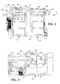
- Figure 2 is a partial, transverse cross sectional view (taken through the elongate axis of the support member) of the rebuncher shown in figure 1 ;
- Figure 3 is a partial, transverse cross sectional view (taken through the elongate axis of the support member) of the rebuncher of figures 1 and 2 , shown in a pivot position;
- Figure 4 is a partial end view of the rebuncher of figures 1 to 3 , shown pivotally attached to a structural member of the media depository, in a pivoted position;
- Figure 5 is a perspective view of a first hinge member of the rebuncher of Figures 1 to 4 .
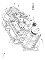
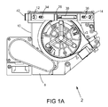
- FIG. 1 With reference to figures 1 and 1A , indicated generally at 1 is part of a media depository. Visible within figure 1 (but most clearly seen in figure 1A ) is a rebuncher unit 2 which is part of the media depository 1. The part of the media depository illustrated in figure 1 includes a transport arrangement 3 including elongated slots 4 on an upper portion thereof.
- a customer feeds notes (not shown) into the depository 1 in bunches.
- the individual notes are presented to a note validator unit (not shown).
- the rebuncher unit 2 reforms the notes into a bunch.
- Each rod 12, 14 has a proximal end 30 adjacent the wall 6 and a distal end 32 adjacent an open side 8 of the body 10; is attached to the wall 6 by a head 17 at its proximal end 30 on the remote side of the wall 6 to the body 10; and, extends through the wall 6 and the body 10, that is, through an opening 20 in the wall 6, through the material of the first body half 16, through the material of the second body half 18 and through an opening 26 in the side 8.
- the body 10 is held in the working position by a unitary latch mechanism 28 which latches the distal ends 32 of the rods 12, 14.
- the latch mechanism 28 is provided with two teardrop-shaped apertures 34, 36 whose spacing matches that of the openings 26 in the side 8.
- the latch mechanism 28 is urged by a spring 38 into its default position in which each of the narrow sections of the apertures 34, 36 is aligned with a corresponding opening 26 in the side 8.
- Each rod 12, 14 has a circumferential groove 40 adjacent its distal end 32 and the narrower part of the apertures 34, 36 are so sized that the web of the latch around the apertures 34, 36 extends into the circumferential groove 40 and latches the rods 12, 14 in place.
- the latch mechanism 28 has a handle 42, and the body 10 is released from the rods 12, 14 by moving the latch mechanism 28 to the disengaged position, against the urging force of the spring 38, so that the web of the latch mechanism 28 is pulled out of the groove 40 and aligns the wider part of the apertures 34, 36 with the opening 26 in the second wall, whereupon, because the wider section of the aperture 34, 36 is bigger than the opening 26, the body 10 is free to slidably move relative to the rods 12, 14.
- a first hinge member in the form of a bushing 48 is slid on to the rod 12. Again, in the working position of the body 10, the bushing 48 sits around the rod 12 in the enlarged diameter part 45 of the first cavity 44.
- the bushing 48 is generally cylindrical except that at one end it has inwardly directed resilient fingers 50 and, at the same end, a pin 52, which is slightly longer than the diameter of the bushing 48, is transversely mounted (in relation to the cylindrical axis of the bushing 48) on the outer cylindrical surface of the bushing 48.
- the pin 52 is mounted generally at its midpoint so that its ends 54, 56 are free, each one projecting in an opposite direction to the other.
- the enlarged diameter part 45 of the first cavity 44 is sized and shaped so as to house the bushing 48 in the support position with the pin 52 uppermost.
- the second cavity 46 which is cylindrical, is the same diameter as the rod 12.
- a second hinge member in the form of two, spaced-apart, j-shaped, hook-like fingers 60 which project such that each one is to an opposite side of the elongate axis of the rod 12.
- the bushing 48 During the first phase of movement of the body 10, the bushing 48 remains stationary on the rod 12, held by the frictional contact between the bushing 48 and the rod 12. Continued removal of the body 10 results in the hook-like fingers 60 engaging the bushing 48, which involves each one of the hook-like fingers 60 hooking around one of the free ends 54, 56 of the pin 52.
- the radius of curvature of the hook-like fingers 60 may be such that the hook-like fingers 60 clip on to the ends 54, 56 of the pin. This engagement marks the beginning of the second phase of movement of the body 10.
- the second phase of movement continues with the body 10 continuing to be moved until it is substantially removed from the rod 12, at which point the resilient fingers 50 of the bushing 48 engage the groove 40 in the rod 12 by extending into it, causing the bushing 48 to lock onto the rod 12. This is the end of the second phase of movement.
- the body 10 is then in the pivot position and, because the body 10 is substantially removed from the rod 12 and the rod 12 no longer extends through the body 10, the fingers 60 and the pin 52 form a pivoting mechanism by which the unit 2 is pivotally attached to the rod 12. In this position, the unit 2 is able to pivot upwardly about the rod 12 as shown in figure 4 .
- the body 10 can be pivoted such that the transverse axis of the body 10 is substantially orthogonal to how it is in the pivot position. With the body 10 in the pivoted-upwards position, known as the service position, it is possible to access the door underneath the rebuncher unit, for example, to free any jams.
- the body 10 When the body 10 is returned (pivoted downwards in this embodiment) to the pivot position, the body 10 can be re-inserted into the media dispenser 1 by sliding it over the rod 12.
Landscapes
- Engineering & Computer Science (AREA)
- Mechanical Engineering (AREA)
- Control Of Vending Devices And Auxiliary Devices For Vending Devices (AREA)
- Pivots And Pivotal Connections (AREA)
- Packaging For Recording Disks (AREA)
- Feeding And Guiding Record Carriers (AREA)
Applications Claiming Priority (1)
| Application Number | Priority Date | Filing Date | Title |
|---|---|---|---|
| US13/250,639 US8622295B2 (en) | 2011-09-30 | 2011-09-30 | Unit of a media depository |
Publications (3)
| Publication Number | Publication Date |
|---|---|
| EP2574579A2 true EP2574579A2 (de) | 2013-04-03 |
| EP2574579A3 EP2574579A3 (de) | 2013-09-04 |
| EP2574579B1 EP2574579B1 (de) | 2014-07-30 |
Family
ID=46799084
Family Applications (1)
| Application Number | Title | Priority Date | Filing Date |
|---|---|---|---|
| EP12182135.9A Active EP2574579B1 (de) | 2011-09-30 | 2012-08-29 | Mediendepot und Verfahren zum Betrieb des Mediendepots |
Country Status (4)
| Country | Link |
|---|---|
| US (1) | US8622295B2 (de) |
| EP (1) | EP2574579B1 (de) |
| CN (1) | CN103030037B (de) |
| BR (1) | BR102012024940B1 (de) |
Families Citing this family (1)
| Publication number | Priority date | Publication date | Assignee | Title |
|---|---|---|---|---|
| CN108280922A (zh) * | 2017-12-29 | 2018-07-13 | 张家港鸿盛电子科技股份有限公司 | 一种即开型彩票自助广告机 |
Family Cites Families (5)
| Publication number | Priority date | Publication date | Assignee | Title |
|---|---|---|---|---|
| JP2752087B2 (ja) * | 1988-06-30 | 1998-05-18 | 株式会社東芝 | 自動取引装置 |
| WO2004061787A2 (en) * | 2002-12-31 | 2004-07-22 | Diebold, Incorporated | Atm currency cassette arrangement |
| CA2733118C (en) * | 2003-03-10 | 2015-04-28 | Diebold, Incorporated | Cash dispensing automated banking machine with tilt out fascia |
| US7004383B2 (en) * | 2003-03-10 | 2006-02-28 | Diebold Self-Service Systems, A Division Of Diebold, Incorporated | ATM currency cassette door arrangement |
| EP1571661A1 (de) * | 2004-03-04 | 2005-09-07 | Thomson Licensing S.A. | Vorrichtung zur Verarbeitung von Medien |
-
2011
- 2011-09-30 US US13/250,639 patent/US8622295B2/en active Active
-
2012
- 2012-08-29 EP EP12182135.9A patent/EP2574579B1/de active Active
- 2012-09-28 BR BR102012024940-5A patent/BR102012024940B1/pt active IP Right Grant
- 2012-09-28 CN CN201210367664.2A patent/CN103030037B/zh active Active
Non-Patent Citations (1)
| Title |
|---|
| None |
Also Published As
| Publication number | Publication date |
|---|---|
| US20130081561A1 (en) | 2013-04-04 |
| CN103030037B (zh) | 2016-01-20 |
| BR102012024940B1 (pt) | 2019-11-26 |
| EP2574579A3 (de) | 2013-09-04 |
| US8622295B2 (en) | 2014-01-07 |
| BR102012024940A2 (pt) | 2013-11-05 |
| CN103030037A (zh) | 2013-04-10 |
| EP2574579B1 (de) | 2014-07-30 |
Similar Documents
| Publication | Publication Date | Title |
|---|---|---|
| EP2096062A2 (de) | Papierfördermechanismus und Papierhandhabungsvorrichtung | |
| US9114952B2 (en) | Device for filling a thin-walled transport container with securities | |
| EP2458125B1 (de) | Geldkassette mit selbstverriegelungsmechanismus | |
| US10617266B2 (en) | Hands-free sheet product dispensers and related methods | |
| CN102619412B (zh) | 车门的关闭锁定装置 | |
| EP2574579B1 (de) | Mediendepot und Verfahren zum Betrieb des Mediendepots | |
| KR101590714B1 (ko) | 금융기기 | |
| CN104813373B (zh) | 介质处理装置 | |
| JP5261660B2 (ja) | 紙幣収納装置 | |
| KR20230052912A (ko) | 프린터 | |
| KR101628206B1 (ko) | 계원용 금융자동화기기 | |
| JP5695755B2 (ja) | 紙葉類処理装置 | |
| EP3931806A1 (de) | Sitzspielgerät | |
| EP2152619B1 (de) | Vorrichtung zur handhabung von wertdokumenten | |
| JP5355427B2 (ja) | 自動取引装置のシャッタ構造 | |
| JP2021046316A (ja) | 後処理装置及び画像形成装置 | |
| EP2156415A1 (de) | Vorrichtung zur zahlung eines vorgegebenen rechnungsbetrages und verfahren annahme von wertdokumenten und ausgabe in einer speichereinrichtung gespeicherter wertdokumente | |
| KR102854703B1 (ko) | 유지보수가 용이한 지폐저장장치 | |
| JP5298818B2 (ja) | 施錠機構 | |
| JP7608673B2 (ja) | 紙葉類取扱装置 | |
| JP4915607B2 (ja) | 遊技機用台間機、及び紙幣取扱装置 | |
| JP2003006703A (ja) | 紙幣識別装置 | |
| KR200302436Y1 (ko) | 지폐류 저장박스 | |
| JPH03210693A (ja) | 紙幣収納装置 | |
| JP5176125B2 (ja) | スライドレール機構、及び金銭取扱い装置 |
Legal Events
| Date | Code | Title | Description |
|---|---|---|---|
| PUAI | Public reference made under article 153(3) epc to a published international application that has entered the european phase |
Free format text: ORIGINAL CODE: 0009012 |
|
| AK | Designated contracting states |
Kind code of ref document: A2 Designated state(s): AL AT BE BG CH CY CZ DE DK EE ES FI FR GB GR HR HU IE IS IT LI LT LU LV MC MK MT NL NO PL PT RO RS SE SI SK SM TR |
|
| AX | Request for extension of the european patent |
Extension state: BA ME |
|
| PUAL | Search report despatched |
Free format text: ORIGINAL CODE: 0009013 |
|
| AK | Designated contracting states |
Kind code of ref document: A3 Designated state(s): AL AT BE BG CH CY CZ DE DK EE ES FI FR GB GR HR HU IE IS IT LI LT LU LV MC MK MT NL NO PL PT RO RS SE SI SK SM TR |
|
| AX | Request for extension of the european patent |
Extension state: BA ME |
|
| RIC1 | Information provided on ipc code assigned before grant |
Ipc: B65H 29/51 20060101AFI20130726BHEP |
|
| 17P | Request for examination filed |
Effective date: 20140304 |
|
| RBV | Designated contracting states (corrected) |
Designated state(s): AL AT BE BG CH CY CZ DE DK EE ES FI FR GB GR HR HU IE IS IT LI LT LU LV MC MK MT NL NO PL PT RO RS SE SI SK SM TR |
|
| RIC1 | Information provided on ipc code assigned before grant |
Ipc: B65H 29/51 20060101AFI20140331BHEP Ipc: G07F 19/00 20060101ALI20140331BHEP |
|
| GRAJ | Information related to disapproval of communication of intention to grant by the applicant or resumption of examination proceedings by the epo deleted |
Free format text: ORIGINAL CODE: EPIDOSDIGR1 |
|
| GRAP | Despatch of communication of intention to grant a patent |
Free format text: ORIGINAL CODE: EPIDOSNIGR1 |
|
| GRAP | Despatch of communication of intention to grant a patent |
Free format text: ORIGINAL CODE: EPIDOSNIGR1 |
|
| INTG | Intention to grant announced |
Effective date: 20140527 |
|
| GRAS | Grant fee paid |
Free format text: ORIGINAL CODE: EPIDOSNIGR3 |
|
| GRAA | (expected) grant |
Free format text: ORIGINAL CODE: 0009210 |
|
| AK | Designated contracting states |
Kind code of ref document: B1 Designated state(s): AL AT BE BG CH CY CZ DE DK EE ES FI FR GB GR HR HU IE IS IT LI LT LU LV MC MK MT NL NO PL PT RO RS SE SI SK SM TR |
|
| REG | Reference to a national code |
Ref country code: GB Ref legal event code: FG4D |
|
| REG | Reference to a national code |
Ref country code: CH Ref legal event code: EP |
|
| REG | Reference to a national code |
Ref country code: DE Ref legal event code: R084 Ref document number: 602012002570 Country of ref document: DE |
|
| REG | Reference to a national code |
Ref country code: AT Ref legal event code: REF Ref document number: 679856 Country of ref document: AT Kind code of ref document: T Effective date: 20140815 |
|
| REG | Reference to a national code |
Ref country code: IE Ref legal event code: FG4D |
|
| REG | Reference to a national code |
Ref country code: DE Ref legal event code: R096 Ref document number: 602012002570 Country of ref document: DE Effective date: 20140911 |
|
| REG | Reference to a national code |
Ref country code: DE Ref legal event code: R084 Ref document number: 602012002570 Country of ref document: DE Effective date: 20140801 |
|
| REG | Reference to a national code |
Ref country code: GB Ref legal event code: 746 Effective date: 20140901 |
|
| REG | Reference to a national code |
Ref country code: AT Ref legal event code: MK05 Ref document number: 679856 Country of ref document: AT Kind code of ref document: T Effective date: 20140730 |
|
| REG | Reference to a national code |
Ref country code: NL Ref legal event code: VDEP Effective date: 20140730 |
|
| REG | Reference to a national code |
Ref country code: LT Ref legal event code: MG4D |
|
| PG25 | Lapsed in a contracting state [announced via postgrant information from national office to epo] |
Ref country code: LT Free format text: LAPSE BECAUSE OF FAILURE TO SUBMIT A TRANSLATION OF THE DESCRIPTION OR TO PAY THE FEE WITHIN THE PRESCRIBED TIME-LIMIT Effective date: 20140730 Ref country code: FI Free format text: LAPSE BECAUSE OF FAILURE TO SUBMIT A TRANSLATION OF THE DESCRIPTION OR TO PAY THE FEE WITHIN THE PRESCRIBED TIME-LIMIT Effective date: 20140730 Ref country code: BG Free format text: LAPSE BECAUSE OF FAILURE TO SUBMIT A TRANSLATION OF THE DESCRIPTION OR TO PAY THE FEE WITHIN THE PRESCRIBED TIME-LIMIT Effective date: 20141030 Ref country code: NO Free format text: LAPSE BECAUSE OF FAILURE TO SUBMIT A TRANSLATION OF THE DESCRIPTION OR TO PAY THE FEE WITHIN THE PRESCRIBED TIME-LIMIT Effective date: 20141030 Ref country code: SE Free format text: LAPSE BECAUSE OF FAILURE TO SUBMIT A TRANSLATION OF THE DESCRIPTION OR TO PAY THE FEE WITHIN THE PRESCRIBED TIME-LIMIT Effective date: 20140730 Ref country code: ES Free format text: LAPSE BECAUSE OF FAILURE TO SUBMIT A TRANSLATION OF THE DESCRIPTION OR TO PAY THE FEE WITHIN THE PRESCRIBED TIME-LIMIT Effective date: 20140730 Ref country code: PT Free format text: LAPSE BECAUSE OF FAILURE TO SUBMIT A TRANSLATION OF THE DESCRIPTION OR TO PAY THE FEE WITHIN THE PRESCRIBED TIME-LIMIT Effective date: 20141202 Ref country code: GR Free format text: LAPSE BECAUSE OF FAILURE TO SUBMIT A TRANSLATION OF THE DESCRIPTION OR TO PAY THE FEE WITHIN THE PRESCRIBED TIME-LIMIT Effective date: 20141031 |
|
| PG25 | Lapsed in a contracting state [announced via postgrant information from national office to epo] |
Ref country code: HR Free format text: LAPSE BECAUSE OF FAILURE TO SUBMIT A TRANSLATION OF THE DESCRIPTION OR TO PAY THE FEE WITHIN THE PRESCRIBED TIME-LIMIT Effective date: 20140730 Ref country code: IS Free format text: LAPSE BECAUSE OF FAILURE TO SUBMIT A TRANSLATION OF THE DESCRIPTION OR TO PAY THE FEE WITHIN THE PRESCRIBED TIME-LIMIT Effective date: 20141130 Ref country code: RS Free format text: LAPSE BECAUSE OF FAILURE TO SUBMIT A TRANSLATION OF THE DESCRIPTION OR TO PAY THE FEE WITHIN THE PRESCRIBED TIME-LIMIT Effective date: 20140730 Ref country code: PL Free format text: LAPSE BECAUSE OF FAILURE TO SUBMIT A TRANSLATION OF THE DESCRIPTION OR TO PAY THE FEE WITHIN THE PRESCRIBED TIME-LIMIT Effective date: 20140730 Ref country code: NL Free format text: LAPSE BECAUSE OF FAILURE TO SUBMIT A TRANSLATION OF THE DESCRIPTION OR TO PAY THE FEE WITHIN THE PRESCRIBED TIME-LIMIT Effective date: 20140730 Ref country code: CY Free format text: LAPSE BECAUSE OF FAILURE TO SUBMIT A TRANSLATION OF THE DESCRIPTION OR TO PAY THE FEE WITHIN THE PRESCRIBED TIME-LIMIT Effective date: 20140730 Ref country code: AT Free format text: LAPSE BECAUSE OF FAILURE TO SUBMIT A TRANSLATION OF THE DESCRIPTION OR TO PAY THE FEE WITHIN THE PRESCRIBED TIME-LIMIT Effective date: 20140730 Ref country code: LV Free format text: LAPSE BECAUSE OF FAILURE TO SUBMIT A TRANSLATION OF THE DESCRIPTION OR TO PAY THE FEE WITHIN THE PRESCRIBED TIME-LIMIT Effective date: 20140730 |
|
| PG25 | Lapsed in a contracting state [announced via postgrant information from national office to epo] |
Ref country code: IT Free format text: LAPSE BECAUSE OF FAILURE TO SUBMIT A TRANSLATION OF THE DESCRIPTION OR TO PAY THE FEE WITHIN THE PRESCRIBED TIME-LIMIT Effective date: 20140730 Ref country code: BE Free format text: LAPSE BECAUSE OF NON-PAYMENT OF DUE FEES Effective date: 20140831 Ref country code: CZ Free format text: LAPSE BECAUSE OF FAILURE TO SUBMIT A TRANSLATION OF THE DESCRIPTION OR TO PAY THE FEE WITHIN THE PRESCRIBED TIME-LIMIT Effective date: 20140730 Ref country code: SK Free format text: LAPSE BECAUSE OF FAILURE TO SUBMIT A TRANSLATION OF THE DESCRIPTION OR TO PAY THE FEE WITHIN THE PRESCRIBED TIME-LIMIT Effective date: 20140730 Ref country code: DK Free format text: LAPSE BECAUSE OF FAILURE TO SUBMIT A TRANSLATION OF THE DESCRIPTION OR TO PAY THE FEE WITHIN THE PRESCRIBED TIME-LIMIT Effective date: 20140730 Ref country code: MC Free format text: LAPSE BECAUSE OF FAILURE TO SUBMIT A TRANSLATION OF THE DESCRIPTION OR TO PAY THE FEE WITHIN THE PRESCRIBED TIME-LIMIT Effective date: 20140730 Ref country code: RO Free format text: LAPSE BECAUSE OF FAILURE TO SUBMIT A TRANSLATION OF THE DESCRIPTION OR TO PAY THE FEE WITHIN THE PRESCRIBED TIME-LIMIT Effective date: 20140730 Ref country code: EE Free format text: LAPSE BECAUSE OF FAILURE TO SUBMIT A TRANSLATION OF THE DESCRIPTION OR TO PAY THE FEE WITHIN THE PRESCRIBED TIME-LIMIT Effective date: 20140730 |
|
| REG | Reference to a national code |
Ref country code: DE Ref legal event code: R097 Ref document number: 602012002570 Country of ref document: DE |
|
| REG | Reference to a national code |
Ref country code: IE Ref legal event code: MM4A |
|
| PLBE | No opposition filed within time limit |
Free format text: ORIGINAL CODE: 0009261 |
|
| STAA | Information on the status of an ep patent application or granted ep patent |
Free format text: STATUS: NO OPPOSITION FILED WITHIN TIME LIMIT |
|
| 26N | No opposition filed |
Effective date: 20150504 |
|
| PG25 | Lapsed in a contracting state [announced via postgrant information from national office to epo] |
Ref country code: IE Free format text: LAPSE BECAUSE OF NON-PAYMENT OF DUE FEES Effective date: 20140829 |
|
| PG25 | Lapsed in a contracting state [announced via postgrant information from national office to epo] |
Ref country code: SI Free format text: LAPSE BECAUSE OF FAILURE TO SUBMIT A TRANSLATION OF THE DESCRIPTION OR TO PAY THE FEE WITHIN THE PRESCRIBED TIME-LIMIT Effective date: 20140730 |
|
| REG | Reference to a national code |
Ref country code: CH Ref legal event code: PL |
|
| PG25 | Lapsed in a contracting state [announced via postgrant information from national office to epo] |
Ref country code: LI Free format text: LAPSE BECAUSE OF NON-PAYMENT OF DUE FEES Effective date: 20150831 Ref country code: CH Free format text: LAPSE BECAUSE OF NON-PAYMENT OF DUE FEES Effective date: 20150831 |
|
| PG25 | Lapsed in a contracting state [announced via postgrant information from national office to epo] |
Ref country code: SM Free format text: LAPSE BECAUSE OF FAILURE TO SUBMIT A TRANSLATION OF THE DESCRIPTION OR TO PAY THE FEE WITHIN THE PRESCRIBED TIME-LIMIT Effective date: 20140730 |
|
| PG25 | Lapsed in a contracting state [announced via postgrant information from national office to epo] |
Ref country code: MT Free format text: LAPSE BECAUSE OF FAILURE TO SUBMIT A TRANSLATION OF THE DESCRIPTION OR TO PAY THE FEE WITHIN THE PRESCRIBED TIME-LIMIT Effective date: 20140730 |
|
| PG25 | Lapsed in a contracting state [announced via postgrant information from national office to epo] |
Ref country code: HU Free format text: LAPSE BECAUSE OF FAILURE TO SUBMIT A TRANSLATION OF THE DESCRIPTION OR TO PAY THE FEE WITHIN THE PRESCRIBED TIME-LIMIT; INVALID AB INITIO Effective date: 20120829 Ref country code: BE Free format text: LAPSE BECAUSE OF FAILURE TO SUBMIT A TRANSLATION OF THE DESCRIPTION OR TO PAY THE FEE WITHIN THE PRESCRIBED TIME-LIMIT Effective date: 20140730 Ref country code: LU Free format text: LAPSE BECAUSE OF NON-PAYMENT OF DUE FEES Effective date: 20140829 Ref country code: TR Free format text: LAPSE BECAUSE OF FAILURE TO SUBMIT A TRANSLATION OF THE DESCRIPTION OR TO PAY THE FEE WITHIN THE PRESCRIBED TIME-LIMIT Effective date: 20140730 |
|
| REG | Reference to a national code |
Ref country code: FR Ref legal event code: PLFP Year of fee payment: 5 |
|
| REG | Reference to a national code |
Ref country code: FR Ref legal event code: PLFP Year of fee payment: 6 |
|
| PG25 | Lapsed in a contracting state [announced via postgrant information from national office to epo] |
Ref country code: MK Free format text: LAPSE BECAUSE OF FAILURE TO SUBMIT A TRANSLATION OF THE DESCRIPTION OR TO PAY THE FEE WITHIN THE PRESCRIBED TIME-LIMIT Effective date: 20140730 |
|
| REG | Reference to a national code |
Ref country code: FR Ref legal event code: PLFP Year of fee payment: 7 |
|
| PG25 | Lapsed in a contracting state [announced via postgrant information from national office to epo] |
Ref country code: AL Free format text: LAPSE BECAUSE OF FAILURE TO SUBMIT A TRANSLATION OF THE DESCRIPTION OR TO PAY THE FEE WITHIN THE PRESCRIBED TIME-LIMIT Effective date: 20140730 |
|
| REG | Reference to a national code |
Ref country code: DE Ref legal event code: R081 Ref document number: 602012002570 Country of ref document: DE Owner name: CARDTRONICS USA, INC. (GESELLSCHAFT NACH DEN G, US Free format text: FORMER OWNER: NCR CORP., DULUTH, GA., US Ref country code: DE Ref legal event code: R082 Ref document number: 602012002570 Country of ref document: DE Representative=s name: V. BEZOLD & PARTNER PATENTANWAELTE - PARTG MBB, DE Ref country code: DE Ref legal event code: R081 Ref document number: 602012002570 Country of ref document: DE Owner name: NCR CORPORATION, ATLANTA, US Free format text: FORMER OWNER: NCR CORP., DULUTH, GA., US |
|
| P01 | Opt-out of the competence of the unified patent court (upc) registered |
Effective date: 20230507 |
|
| REG | Reference to a national code |
Ref country code: DE Ref legal event code: R081 Ref document number: 602012002570 Country of ref document: DE Owner name: CARDTRONICS USA, INC. (GESELLSCHAFT NACH DEN G, US Free format text: FORMER OWNER: NCR CORPORATION, ATLANTA, GA, US |
|
| PGFP | Annual fee paid to national office [announced via postgrant information from national office to epo] |
Ref country code: DE Payment date: 20250827 Year of fee payment: 14 |
|
| PGFP | Annual fee paid to national office [announced via postgrant information from national office to epo] |
Ref country code: GB Payment date: 20250827 Year of fee payment: 14 |
|
| PGFP | Annual fee paid to national office [announced via postgrant information from national office to epo] |
Ref country code: FR Payment date: 20250825 Year of fee payment: 14 |