EP2574376A1 - Hantelsystem mit Hantelgewichten und einem Griff - Google Patents
Hantelsystem mit Hantelgewichten und einem Griff Download PDFInfo
- Publication number
- EP2574376A1 EP2574376A1 EP11183307A EP11183307A EP2574376A1 EP 2574376 A1 EP2574376 A1 EP 2574376A1 EP 11183307 A EP11183307 A EP 11183307A EP 11183307 A EP11183307 A EP 11183307A EP 2574376 A1 EP2574376 A1 EP 2574376A1
- Authority
- EP
- European Patent Office
- Prior art keywords
- dumbbell
- locking
- locking slide
- handle
- pin
- Prior art date
- Legal status (The legal status is an assumption and is not a legal conclusion. Google has not performed a legal analysis and makes no representation as to the accuracy of the status listed.)
- Granted
Links
- 238000003780 insertion Methods 0.000 claims abstract description 41
- 230000037431 insertion Effects 0.000 claims abstract description 41
- 230000005540 biological transmission Effects 0.000 claims abstract description 12
- 230000000717 retained effect Effects 0.000 abstract 1
- 238000012549 training Methods 0.000 description 4
- 230000000694 effects Effects 0.000 description 3
- 239000013013 elastic material Substances 0.000 description 3
- 238000013461 design Methods 0.000 description 2
- 230000003993 interaction Effects 0.000 description 2
- 230000007423 decrease Effects 0.000 description 1
- 238000006073 displacement reaction Methods 0.000 description 1
- 238000007654 immersion Methods 0.000 description 1
- 239000003550 marker Substances 0.000 description 1
- 238000000034 method Methods 0.000 description 1
- 238000012544 monitoring process Methods 0.000 description 1
- 210000003205 muscle Anatomy 0.000 description 1
- 230000003287 optical effect Effects 0.000 description 1
- 230000007704 transition Effects 0.000 description 1
Images






Classifications
-
- A—HUMAN NECESSITIES
- A63—SPORTS; GAMES; AMUSEMENTS
- A63B—APPARATUS FOR PHYSICAL TRAINING, GYMNASTICS, SWIMMING, CLIMBING, OR FENCING; BALL GAMES; TRAINING EQUIPMENT
- A63B21/00—Exercising apparatus for developing or strengthening the muscles or joints of the body by working against a counterforce, with or without measuring devices
- A63B21/06—User-manipulated weights
- A63B21/072—Dumb-bells, bar-bells or the like, e.g. weight discs having an integral peripheral handle
- A63B21/075—Dumb-bells, bar-bells or the like, e.g. weight discs having an integral peripheral handle with variable weights, e.g. weight systems with weight selecting means for bar-bells or dumb-bells
-
- A—HUMAN NECESSITIES
- A63—SPORTS; GAMES; AMUSEMENTS
- A63B—APPARATUS FOR PHYSICAL TRAINING, GYMNASTICS, SWIMMING, CLIMBING, OR FENCING; BALL GAMES; TRAINING EQUIPMENT
- A63B21/00—Exercising apparatus for developing or strengthening the muscles or joints of the body by working against a counterforce, with or without measuring devices
- A63B21/06—User-manipulated weights
- A63B21/072—Dumb-bells, bar-bells or the like, e.g. weight discs having an integral peripheral handle
- A63B21/0726—Dumb bells, i.e. with a central bar to be held by a single hand, and with weights at the ends
-
- A—HUMAN NECESSITIES
- A63—SPORTS; GAMES; AMUSEMENTS
- A63B—APPARATUS FOR PHYSICAL TRAINING, GYMNASTICS, SWIMMING, CLIMBING, OR FENCING; BALL GAMES; TRAINING EQUIPMENT
- A63B2208/00—Characteristics or parameters related to the user or player
- A63B2208/12—Characteristics or parameters related to the user or player specially adapted for children
Definitions
- the invention relates to a dumbbell system with at least one weight and a handle dumbbell.
- a dumbbell is known as a training device for training the shoulder and arm muscles.
- An intensive and regular fitness and strength training is usually held in appropriately equipped gyms.
- a trainer is supervised by a trainer, who teaches the exerciser training exercises and pays attention to their proper execution by the trainer.
- the dumbbell has a support rod and weights at the two ends of the support rod, the support rod serving as a handle and the weights being releasably secured to the support rod.
- the weights are formed as discs, each with a central hole, with which the weights can be placed on the support rod and fixed, for example with a nut on a formed on the handle end rod thread.
- the end of the handrail is made accessible and one or more weights can be placed on the handrail.
- the weights are attached to the handrail.
- the problem here is that the replacement of the weights is cumbersome because for a secure hold of the weights, the mother and the support rod must be equipped with several to be overcome by turning threads. Furthermore, for a secure hold of the weights must always be taken to ensure that the mother is securely and firmly tightened.
- the object of the invention is to provide a dumbbell system that is easy and safe to use.
- the dumbbell system has at least one dumbbell weight and a handle, which has an axis and a handle tube which is arranged concentrically around the axis and rotatable about it, the axis projecting in the axial longitudinal direction with a pin having an eccentric, the weight of the dumbbell having a dumbbell weight body, in which a Einsteckschlitz is formed, which extends from the edge of the dumbbell weight body to its center region, on which a locking projection is formed and in which is delimited by a slot bottom of the insertion slot, which is formed on the pin so coordinated that the pin at the edge of Dumbbell weight with a Einsteckschlitz engageable and displaceable up to the slot base transversely to the axial longitudinal direction and arranged on slot base and the eccentric positively rotationally engageable in an end position, and wherein the handle has a locking slide and a transmission with which the Ver locking slide with the axis and the handle tube is coupled such that by rotation of the handle tube relative to the axis of the locking slide longitudinal
- the transmission By rotating the handle tube, the transmission is actuated, whereby the locking slide can be brought into its unlocked position and its locking position.
- the axis of the eccentric in the insertion slot is rotationally positively supported, so that relative to the axis is relatively moved during rotation of the handle tube.
- This will be the drive for the transmission generated, with which the twisting movement of the handle tube is translated into a longitudinal displacement of the locking slide.
- the handle has a single translational degree of freedom transverse to the axial longitudinal direction along the insertion slot away from the slot bottom.
- the locking slide is brought into its locking position, the locking slide is engaged with the locking projection, so that this translational degree of freedom of the handle is released. This is achieved in that the locking projection is arranged and cooperates with the locking slide, that retraction of the handle is inhibited from the insertion slot.
- the handle is securely attached to the dumbbell weight.
- the locking slide can be brought into its unlocked position and into its locking position by the rotation of the handle tube, a simple release of the handle of the weight of the dumbbell and a simple setting of the handle on the weight of the dumbbell is possible.
- the twisting can be done easily with one hand, making the operation of the dumbbell system easy.
- the transmission is preferably constructed so that its transmission characteristic is such that, for example, with a quarter turn of the handle tube of the locking slide from its unlocked position in its locking position and vice versa can be brought.
- the locking projection for engagement with the locking slide is formed by a first bevel of the weight of the dumbbell around the slot bottom, which surrounds the pin in its end position by 180 ° C.
- the first chamfer edges the slot base, wherein the C-shaped encompassing by 180 ° of the pin this has the degree of freedom transverse to the axial longitudinal axis of the insertion slot, when the locking projection is in the unlocked position.
- the first chamfer has a C-shaped course around the pin, wherein at the two ends of the C-shaped course each of the first chamfer an undercut based on the degree of freedom is formed.
- the effect of the locking projection is achieved because, when it is in engagement with the locking slide, in an attempt to extract the handle from the insertion slot of the locking projection abuts the undercut of the first chamfer.
- locking of the handle to the weight of the dumbbell can be achieved if the locking projection is inserted into the first chamfer and thereby can not be displaced beyond the undercut of the first chamfer.
- the first chamfer bounds the slot bottom, it extends radially outside of the slot bottom. The consequence of this is that the undercuts of the first bevel are arranged in the region of the insertion slot outside the slot bottom.
- the inner edge of the first chamfer runs together with the slot base and surrounds the pin in its end position C-shaped by 180 °.
- the outer edge of the first chamfer is arranged radially outside the inner edge, whereby an angle of more than 180 ° is circumscribed when the C-shaped embracing of the pin from the outer edge, depending on how deep the first chamfer is formed.
- it can be determined by the depth of the first bevel, by how much more than 180 °, the outer edge of the first bevel engages the pin C-shaped, whereby the size of the undercuts of the first bevel is defined.
- the locking slide is preferably formed as a sleeve, which is arranged between the handle tube and the axis and to this concentrically.
- the locking slide in engagement with the first chamfer and the locking slide is at least partially pushed over the journal.
- engages in the locking position of the sleeve formed as the locking slide in the first chamfer whereby the sleeve cooperates with the undercut of the first chamfer so that the locking position and the first chamfer the locking position is achieved.
- the sleeve is at least partially pushed over the pin, engages over the pin projecting portion of the sleeve in the first chamfer.
- the sleeve is to be pushed back away from the pin, so that the sleeve with the first bevel disengaged, whereby upon removal of the handle from the insertion slot, the sleeve is movable past the undercut of the first chamfer.
- the locking slide has preferably for engaging with the locking projection on a cooperating with this and arranged on the front second bevel on.
- the first and the second chamfer are preferably equipped with the same chamfer angle and the same depth, so that in the locking position the locking slide with its second chamfer lies flat against the first chamfer.
- the first chamfer extends around the slot base and is formed inclined to the axial longitudinal direction according to its chamfer angle. If the locking slide is pushed from the unlocked position into the locking position, the locking slide engages in the first chamfer and finally touches the surface of the first chamfer. If the rotationally symmetric axis of the slot bottom, with the axis of rotation of the first bevel coincides, do not coincide with the longitudinal axis of the pin, the first contact of the locking slide with the first chamfer usually takes place selectively, whereby upon further immersion of the locking slide in the first chamfer of this centering effect of the axis with respect to the Rotation axis of the first bevel takes place.
- the handle when moving the locking slide from the unlocking position to the locking position, the handle is brought into position relative to the weight of the dumbbell.
- the interaction of the first phase with the second phase results in both locking the handle to the dumbbell weight and positioning the handle relative to the weight of the dumbbell.
- the centering effect of the first bevel works particularly well when the locking slide is designed as the sleeve whose end face has the second chamfer.
- the second chamfer slides on the first chamfer, wherein in the locking position, both chamfers lie flat against each other.
- the transmission preferably has a screw drive, with which the handle tube is coupled to the locking slide, so that a rotation relative to the axis of the handle tube in a longitudinal movement of the locking slide in the axial direction is translatable.
- the screw has a fixed to the inside of the handle tube and radially extending drive pin and the locking slide on a thread-extending backdrop with which the drive pin is engaged, so that upon rotation of the handle tube, the drive pin takes the locking slide via the scenery.
- the gate preferably has a first gate area, in which the drive pin is arranged when the locking slide is arranged in the unlocked position, and a second gate area, in which the drive pin is arranged when the locking slide is arranged in the locking position, the pitch of the Backdrop in the first Setting area is higher than in the second setting area.
- the drive pin is also rotated, causing the drive pin slides in the scenery according to their leadership. Due to the thread-like design of the gate, the rotational movement of the drive pin is translated into a longitudinal movement of the locking slide, whereby the locking slide can be brought by the corresponding rotation of the handle tube in the unlocked position and in the locked position.
- the locking slide can be moved quickly when it is disengaged from the first chamfer, wherein the movement speed of the locking slide is reduced as soon as the locking slide is inserted into the first chamfer and centered by this.
- the transmission comprises a linear bearing, with which the locking slide is rotationally fixed to the axis and slidably coupled in the axial longitudinal direction.
- the linear bearing is a linear ball bearing, wherein both in the axis and in the locking slide, which is designed as the sleeve, two mutually congruent and achslnatureslegisparallel extending grooves are formed, into which a ball is inserted. Due to the torsionally rigid mounting of the locking slide on the axis with the linear bearing is advantageously achieved that when translating the twisting movement of the handle tube on the longitudinal movement of the locking slide this is supported against undesired rotation on the axis of the linear bearing.
- the insertion slot preferably opens from the slot bottom to the edge of the dumbbell weight V-shaped.
- the eccentric on a side facing away from the journal center is thicker than the journal and the insertion slot has a width substantially equal to the thickness of the journal, so that in the end position of the journal the eccentric faces away from the slot base is.
- the insertion slot is easy because the insertion slot at the edge of the dumbbell weight has a greater width than the pin is thick. Due to the V-shaped course of the insertion slot from the edge of the dumbbell weight to the slot base, the pin is guided by the insertion slot into the central position of the dumbbell weight when the handle is moved into the end position.
- the handle can only be brought into the end position when the eccentric is arranged away from the slot base in the insertion slot, since the eccentric is formed on its side facing away from the journal center thicker than the pin. If the eccentric arranged facing the slot base, the eccentric with the side that is thicker than the pin would get stuck in the insertion slot when bringing the handle into the end position. This prevents advantageous that the handle positioned incorrectly, namely facing the slot base with the eccentric is mounted on the dumbbell weight, whereby the pin would not be brought into the end position by a blockade of the eccentric on the slot bottom.
- the dumbbell weight body preferably has a flattening, with which the weight of the dumbbell can be stored in a rotationally fixed manner on a base during a twisting operation of the grip tube.
- a torque is transmitted to the dumbbell weight body on the support of the eccentric in the insertion slot against which the weight body dumbbell is to support.
- the flattening of the dumbbell weight body is a simple support against the unwanted twisting of the dumbbell weight body in the Actuation of the handle tube created when the weight body dumbbell is placed on the pad.
- the pin preferably has a collar facing away from the locking slide and the dumbbell weight body is preferably adapted to the collar shaped such that the dumbbell weight body between the collar and the locking slide when it is in the locking position, fixed in the axial direction.
- dumbbell weight body On the locking slide of the weight body dumbbell is supported in the one axial longitudinal direction, whereas with the federal government of the dumbbell weight body is supported in the other axial direction.
- the dumbbell weight body in the axial longitudinal direction has no degree of freedom and, when the locking slide is in the locking position, is firmly attached to the handle.
- the dumbbell system preferably has a fixing device, with which the dumbbell weight body, when the locking slide is in the locking position, on the handle tube from the outside releasably secured against rotation.
- the handle tube for bringing the locking slide from the locking position to the unlocked position can only be actuated when the fixing device is released and the handle tube can be rotated relative to the weight body dumbbell.
- the dumbbell weight body preferably has a cavity that is equipped with a predetermined weight element.
- a predetermined weight element e.g., a weight that is equipped with a predetermined weight element.
- the dumbbell weight bodies having the same dimensions for standardization but being provided with different weight elements.
- the dumbbell system has a plurality of dumbbell weights, which are each equipped with different heavy weight elements, so that at least one of the plurality of dumbbell weights predetermined dumbbell weight on the handle under Vermosbetuschist the handle tube is releasably fixed.
- a dumbbell system 1 has a handle 2 and a first dumbbell weight 3 and a second dumbbell weight 4.
- the handle 2 is rod-shaped and has two longitudinal ends facing away from each other, wherein the first dumbbell weight 3 is attached to the one longitudinal end and the second dumbbell weight 4 to the other longitudinal end.
- the two dumbbell weights 3, 4 are of identical design, so that only the dumbbell weight 3 is described below in a representative manner for the two dumbbell weights 3, 4.
- the dumbbell weight 3 has a dumbbell weight body 5, which is cylindrical.
- the dumbbell weight body 5 has on its cylindrically curved surface two mutually remote and mutually parallel flattenings 6, whereby the dumbbell weight body 5 can be placed for example on a flat surface.
- the dumbbell weight body 5 is hollow, wherein a cavity 7 is provided in the interior of the dumbbell weight body 5. In the cavity 7, one or more weight elements are optionally accommodated, whereby the mass of the dumbbell weight 3 can be determined by their dimensions and number.
- the weight-weighted body 5 has an insertion slot 8.
- the insertion slot 8 extends at the handle 2 facing the front side of the dumbbell weight body 5 of the outer wheel towards the center.
- the insertion slot 8 has two mutually opposite guide flanks 9, which extend substantially parallel to the flattenings 6, wherein the distance decreases from the outer edge of the dumbbell weight body 5 to the center, so that the insertion slot 8 seen in the direction of the cylinder axis of the dumbbell weight body 5 a V -shaped course.
- In the center of the dumbbell weight body 5 of the insertion slot 8 of a Slit bottom 10 limited, which has a cylindrical shell-like shape about the cylinder axis of the dumbbell weight body 5.
- a ring recess 13 is provided in the dumbbell weight body 5, which is formed as a first chamfer 18.
- the slot bottom 10 extends over an angle of 180 °, so that the inner edge of the first chamfer 18 also covers the angle of 180 °.
- the front regions 15, 16 are arranged with their chamfer surfaces facing away from the guide flanks 9, so that a locking projection 14 is formed by the front regions 15, 16.
- the region of the first chamfer 18 between the front regions 15, 16 is a rear region 17 of the first chamfer 18, on which the fixing recess 12 is arranged adjacent.
- the handle 2 has an axis 19 which has a pin 20 at its longitudinal ends.
- the pin 20 is cylindrical, whose cylinder axis coincides with the axial longitudinal direction 19.
- a portion of the cylinder surface is a spine 21, on the opposite an eccentric 22 is formed on the pin 20 and radially protrudes from the pin 20.
- the eccentric 22 has an eccentric 23, which is arranged facing away from the spine 21.
- the pin 20 is inserted in the insertion slot 8 to the slot bottom 10.
- the slot bottom 10, the pin 20 and the eccentric 22 are dimensioned matched to one another that the pin 20 rests with its spine 21 flat on the slot base 10 and the eccentric 22 extends with its eccentric 23 in the eccentric slot 8 along the guide flanks 9, wherein the eccentric 22 bears against the guide flanks 9.
- this has a collar 24, which projects radially from the pin 20. If the handle 2 is mounted on the weight of the dumbbell 3, the collar 24 engages behind the dumbbell weight body 5, in that the collar 24 is in engagement with the undercut 11.
- the collar 24 has a pin 20 associated annular first stop surface 25, with which the collar 24 abuts the undercut when the pin 20 is pulled axially from the insertion slot 8.
- a device cavity 26 is provided, which is open to the spine 21 outward.
- an optical sensor instrument can be accommodated with which a mounted at the appropriate location on the slot base 10 marker can be scanned.
- the marking indicates how heavy the weight of the dumbbell 3 is, so that, for example, monitoring of the fitting of the handle 2 with the weight of the dumbbell 3 can be effected with the sensor instrument.
- the handle 2 further comprises a handle tube 27, in which the axis 19 is arranged concentrically.
- the outside of the handle tube 27 is formed by a gripping surface 28, with which the handle can be touched.
- the handle tube 27 each have a drive pin 29 which is fixed to the handle tube 27 and extends radially inwardly.
- each end face of the handle tube 27 each forms a second stop surface 30 on which the dumbbell weight body 5 is supported when the dumbbell weight 3 is mounted on the handle 2.
- the first stop surface 25 of the Bunds 24 and the second stop surface 30 of the handle tube 27 are arranged at an axial distance from each other such that between the stop surfaces 25, 30 of the dumbbell weight body 5 is fixed in the axial direction.
- an annular groove is provided in which, for example, an elastic material, such as rubber, is introduced, whereby the fixing of the dumbbell weight body 5 with the stop surfaces 25, 30 under a Bias caused by the elastic material is accomplished. Characterized a game between the abutment surfaces 25, 30 and the dumbbell weight body 5 is bridged, wherein the dumbbell weight body 5 is mounted without play in the axial longitudinal direction of the handle 2. Due to the fact that the elastic material can yield, an easy-to-handle assembly of the weight of the dumbbell 3 on the handle 2 is still possible.
- a prestressed locking block 31 is respectively provided on its front side, which is dimensioned and arranged in such a way matched to the Fixieraussparung 12, that when the handle 2 is in its mounting position, the locking block 31 biased into the Fixieraussparung 12 engages.
- the grip tube 27 is locked against rotation relative to the weight body 5 by the lock formed by the locking block 31 in the fixing recess 12.
- the locking block 31 protrudes axially from the locking recess 12 and is accessible from outside the grip tube 27, so that the locking block 31 can be pressed out of the fixing recess 12 against its bias, as a result of which the rotational locking of the grip tube 27 relative to the weight body 5 is canceled again.
- the handle 2 has a return spring 32 which acts both on the handle tube 27 and on the axis 19 and is biased such that the return spring 32 the Disassembly process of the handle 2 supported by the dumbbell weight 3.
- the handle 2 has a locking slide 33, which is formed as a sleeve, and is provided respectively at the longitudinal ends of the handle 2.
- the locking slide 33 is slidably disposed over the pin 20 and about the axis 19, wherein the locking slide 33 has on its free longitudinal end of the axis 19 side facing a locking front 34.
- the locking front 34 is formed as a second chamfer 35, which is dimensioned as a counterpart to the first chamfer 18.
- a linear bearing 36 is provided, with which the locking slide 33 is longitudinally displaceable in the longitudinal direction but rotationally mounted on the axis 19.
- the locking slide 33 has in its cylindrical outer side a link 37, which extends in a thread-like manner in the locking slide 33, wherein the drive pin 29 rests in the slot 37.
- the link 37 has at its one end a first link area 38 and at its other end a second link area 39, the first link area 38 facing the adjacent longitudinal end of the axis 19 and the second link area 39 is disposed away from the adjacent longitudinal end of the axis 19.
- the slope of the thread-like course of the link 37 is greater in the first gate area 38 than in the second gate area 39.
- the handle 2 of the dumbbell weight 3 is spatially separated.
- the handle 2 is to be grasped by hand on the gripping surface 28, wherein the weight of the dumbbell 3 is ready placed on its flattening 6.
- the handle 2 is to be guided horizontally to the dumbbell weight 3, wherein the axial longitudinal direction with the cylinder axis of the dumbbell weight body 5 is parallel.
- the handle 2 is to be guided on the outer edge of the dumbbell weight body 5 to the insertion slot 8, wherein the pin 20 in the insertion slot. 8 is introduced so that the collar 24 engages behind the undercuts 11 and that the eccentric 22, the slot base 10 is arranged facing away.
- the handle 2 is to be brought into its end position, in which the spine 21 bears against the slot bottom 10.
- the longitudinal axis of the axis 19 substantially coincides with the cylinder axis of the weight-weighted body 5.
- the locking block 31 is out of engagement with the fixing recess 12.
- the locking slide 33 is in an unlocking position in which the locking slide 33 has its maximum possible axial distance from the dumbbell weight body 5, wherein the drive pin 29 engages in the link 37 in the first link area 38.
- the dumbbell weight body 5 is determined by the positive connection between the stop surfaces 25 and 30 together with the undercuts 11 in the axial direction.
- the return spring 32 biases the grip tube 27 relative to the axis 19 such that the drive pin 29 is pressed into the first link region 38 of the link 37 and thus the rotational position of the grip tube 27 is stabilized.
- the locking slide 33 is to be brought from its unlocked position into its locking position. This can be done by manually rotating the handle tube 27 in the direction of rotation, which is released due to the stop of the drive pin 29 in the link area 38. When rotating the handle tube 27 in this direction of rotation is to work against the bias of the return spring 32.
- the drive pin 29 moves through the link 37 from the unlocked position to an intermediate position and finally into a locking position, in which the drive pin 29 is arranged in the second link area 39. In the locking position, the drive pin 29 in the second gate area 39 abut the link 37.
- the locking slide 33 is brought into the locked position, the locking slide 33 engages with its second bevel 35 more and more in the Ring recess 13 with its first chamfer 18, whereby the handle 2 with the locking slide 33 on the dumbbell weight body 5 with the cooperation of the chamfers 18, 35 is centered.
- Characterized in that the locking slide engages with its locking front 34 in the annular recess 33 is formed with the front portions 15, 16 of the locking projection 14 of the annular recess 13 a positive connection through which a movement of the handle 2 away from the slot base 10 is blocked.
- the axis 19 is held against rotation relative to the dumbbell weight body 5 by applying the eccentric 22 to one of the guide flanks 9 of the Einsteckschlitzes 8.
- the locking block 31 is arranged on the Fixieraussparung 12 such that the locking block 31 is driven by its bias in the Fixieraussparung 12 and engages in this.
- the grip tube 27 is locked against rotation relative to the dumbbell weight body 5.
- the locking block 31 is to bring against its bias from the Fixieraussparung 12, so that the locking block 31 is no longer with the Fixieraussparung 12 in Intervention is.
- the rotation of the handle tube 27 is released relative to the axis 19 and the weight body 5 dumbbell.
- the grip tube 27 is manually rotated so far until the drive pin 29 abuts the link 37 in the first link area 38.
- the locking slide 33 is pushed from the locking position into the unlocked position, whereby the locking slide 33 is brought out of engagement with the annular recess 13.
- the handle 2 has a degree of freedom along the guide flanks 9 of the insertion slot 8 away from the slot bottom 10.
- the handle 2 can be taken out of the insertion slot 8 and disassembled from the dumbbell weight 3.
Landscapes
- Health & Medical Sciences (AREA)
- Life Sciences & Earth Sciences (AREA)
- Biophysics (AREA)
- Orthopedic Medicine & Surgery (AREA)
- General Health & Medical Sciences (AREA)
- Physical Education & Sports Medicine (AREA)
- Mutual Connection Of Rods And Tubes (AREA)
Abstract
Description
- Die Erfindung betrifft ein Hantelsystem mit mindestens einem Hantelgewicht und einem Griff.
- Eine Hantel ist als ein Trainingsgerät zum Trainieren der Schulter- und der Armmuskulatur bekannt. Ein intensives und regelmäßiges Fitness- und Krafttraining wird üblicherweise in entsprechend ausgestatteten Fitnessstudios abgehalten. Häufig wird hierbei ein Trainierender von einem Trainer betreut, der dem Trainierenden Trainingsübungen beibringt und auf deren ordnungsgemäße Durchführung durch den Trainierenden achtet. Die Hantel weist eine Haltestange und Gewichte an den beiden Enden der Haltestange auf, wobei die Haltestange als ein Griff dient und die Gewichte an der Haltestange lösbar befestigt sind. Herkömmlich sind die Gewichte als Scheiben mit jeweils einem zentrischen Loch ausgebildet, mit dem die Gewichte auf die Haltestange gesteckt und beispielsweise mit einer Mutter an einem an dem Haltestangenende ausgebildeten Gewinde festgelegt werden können. Durch das Lösen und das Herunterschrauben der Mutter von dem Gewinde ist das Ende der Haltestange zugänglich gemacht und es können ein oder mehrere Gewichte auf die Haltestange gesteckt werden. Indem die Mutter auf das Gewinde geschraubt wird, werden die Gewichte an der Haltestange befestigt. Problematisch hierbei ist, dass das Auswechseln der Gewichte umständlich ist, da für einen sicheren Halt der Gewichte die Mutter und die Haltestange mit mehreren durch Drehung zu überwindenden Gewindegängen ausgestattet werden müssen. Weiterhin muss für einen sicheren Halt der Gewichte immer darauf geachtet werden, dass die Mutter sicher und fest angezogen ist.
- Aufgabe der Erfindung ist es ein Hantelsystem zu schaffen, das einfach und sicher in der Handhabung ist.
- Die Aufgabe wird gelöst mit den Merkmalen des Patentanspruchs 1. Bevorzugte Ausgestaltungen dazu sind in den weiteren Patentansprüchen angegeben.
- Das erfindungsgemäße Hantelsystem weist mindestens ein Hantelgewicht und einen Griff auf, der eine Achse und ein konzentrisch um die Achse sowie um diese verdrehbar angeordnetes Griffrohr aufweist, von dem in Achslängsrichtung die Achse mit einem einen Exzenter aufweisenden Zapfen vorsteht, wobei das Hantelgewicht einen Hantelgewichtkörper aufweist, in dem ein Einsteckschlitz geformt ist, der sich vom Rand des Hantelgewichtkörpers bis zu dessen Zentrumsbereich erstreckt, an dem ein Verriegelungsvorsprung angeformt und in dem von einem Schlitzgrund der Einsteckschlitz begrenzt ist, der auf dem Zapfen derart abgestimmt geformt ist, dass der Zapfen am Rand des Hantelgewichts mit einem Einsteckschlitz in Eingriff bringbar und bis zum Schlitzgrund quer zur Achslängsrichtung verschiebbar und am Schlitzgrund angeordnet sowie von dem Exzenter formschlüssig verdrehfest in eine Endlage bringbar ist, und wobei der Griff einen Verriegelungsschieber und ein Getriebe aufweist, mit dem der Verriegelungsschieber mit der Achse und dem Griffrohr derart gekoppelt ist, dass durch Verdrehen des Griffrohrs relativ zur Achse der Verriegelungsschieber längsverschiebbar und dadurch in eine Entriegelungsstellung, in der der Verriegelungsschieber mit einem Verriegelungsvorsprung außer Eingriff steht, und in eine Verriegelungsstellung bringbar ist, in der der Verriegelungsschieber mit dem Verriegelungsvorsprung derart in Eingriff steht, dass der Zapfen von dem Verriegelungsvorsprung via den Verriegelungsschieber zusammen mit dem Schlitzgrund quer zur Achslängsrichtung gehalten ist, wodurch das Hantelgewicht an den Griff lösbar festlegbar ist durch ein Verdrehen des Griffrohrs relativ zu dem Hantelgewichtkörper.
- Durch Verdrehen des Griffrohrs wird das Getriebe betätigt, wodurch der Verriegelungsschieber in seine Entriegelungsstellung und seine Verriegelungsstellung bringbar ist. Dabei ist die Achse von dem Exzenter in dem Einsteckschlitz formschlüssig verdrehfest abgestützt, so dass beim Verdrehen des Griffrohrs dieses bezogen auf die Achse relativbewegt ist. Daraus wird der Antrieb für das Getriebe generiert, mit dem die Verdrehbewegung des Griffrohrs in eine Längsverschiebung des Verriegelungsschiebers übersetzt wird. Beim Verdrehen des Griffrohrs derart, dass der Verriegelungsschieber in seine Entriegelungsstellung gebracht wird, wird von dem Getriebe der Verriegelungsschieber weg von dem Hantelgewichtkörper bewegt. Im Gegensatz dazu wird der Verriegelungsschieber zum Hantelgewichtkörper hin bewegt, wenn durch das Verdrehen des Griffrohrs der Verriegelungsschieber von dem Getriebe angetrieben in seine Verriegelungsstellung gebracht wird.
- Ist der Zapfen in seiner Endlage, stößt der Zapfen an den Schlitzgrund an. Befindet sich dabei der Verriegelungsschieber in der Entriegelungsstellung, so hat der Griff einen einzigen translatorischen Freiheitsgrad quer zur Achslängsrichtung entlang des Einsteckschlitzes weg vom Schlitzgrund. Wird der Verriegelungsschieber in seine Verriegelungsstellung gebracht, steht der Verriegelungsschieber mit dem Verriegelungsvorsprung in Eingriff, so dass dieser translatorische Freiheitsgrad des Griffs aufgehoben ist. Dies wird dadurch erreicht, dass der Verriegelungsvorsprung derart angeordnet ist und mit dem Verriegelungsschieber so zusammenwirkt, dass ein Herausziehen des Griffs aus dem Einsteckschlitz gehemmt ist. Somit ist der Griff an dem Hantelgewicht sicher befestigt.
- Dadurch, dass durch das Verdrehen des Griffrohrs der Verriegelungsschieber in seine Entriegelungsstellung und in seine Verriegelungsstellung bringbar ist, ist ein einfaches Lösen des Griffs von dem Hantelgewicht und ein einfaches Festlegen des Griffs an dem Hantelgewicht ermöglicht. Das Verdrehen kann mit einer Hand leicht ausgeführt werden, wodurch die Bedienung des Hantelsystems einfach ist. Aus praktischen Gründen ist bevorzugt das Getriebe derart konstruiert, dass seine Übersetzungscharakteristik so ist, dass beispielsweise mit einer Vierteldrehung des Griffrohrs der Verriegelungsschieber von seiner Entriegelungsstellung in seine Verriegelungsstellung und umgekehrt bringbar ist.
- Es ist bevorzugt, dass der Verriegelungsvorsprung zum Ineingriffstehen mit dem Verriegelungsschieber von einer ersten Fase des Hantelgewichts um den Schlitzgrund gebildet ist, der den Zapfen in dessen Endlage um 180° C-förmig umgreift. Dadurch berandet die erste Fase den Schlitzgrund, wobei durch das C-förmige Umgreifen um 180° des Zapfens dieser den Freiheitsgrad quer zur Achslängsrichtung der Achse entlang des Einsteckschlitzes hat, wenn der Verriegelungsvorsprung in der Entriegelungsstellung ist. Die erste Fase hat einen C-förmigen Verlauf um den Zapfen, wobei an den beiden Enden des C-förmigen Verlaufs jeweils von der ersten Fase eine Hinterschneidung bezogen auf den Freiheitsgrad ausgebildet ist. Mit dieser Hinterschneidung ist die Wirkung des Verriegelungsvorsprungs erzielt, da, wenn sie in Eingriff mit dem Verriegelungsschieber steht, beim Versuch des Herausziehens des Griffs aus dem Einsteckschlitz der Verriegelungsvorsprung an die Hinterschneidung der ersten Fase anstößt. Somit kann ein Verriegeln des Griffs an das Hantelgewicht dadurch erreicht werden, wenn der Verriegelungsvorsprung in die erste Fase eintaucht und dadurch nicht über die Hinterschneidung der ersten Fase hinweg verschiebbar ist. Dadurch, dass die erste Fase den Schlitzgrund berandet, erstreckt sie sich radial außerhalb des Schlitzgrunds. Die Folge hiervon ist, dass die Hinterschneidungen der ersten Fase im Bereich des Einsteckschlitzes außerhalb des Schlitzgrunds angeordnet sind.
- Der Innenrand der ersten Fase verläuft zusammen mit dem Schlitzgrund und umgreift den Zapfen in dessen Endlage C-förmig um 180°. Hingegen ist der Außenrand der ersten Fase radial außerhalb des Innenrands angeordnet, wodurch beim C-förmigen Umgreifen des Zapfens von dem Außenrand ein Winkel von mehr als 180° umstrichen ist, je nachdem wie tief die erste Fase ausgebildet ist. Somit kann durch die Tiefe der ersten Fase bestimmt werden, um wie viel mehr als 180° der Außenrand der ersten Fase den Zapfen C-förmig umgreift, wodurch die Größe der Hinterschneidungen der ersten Fase definiert ist.
- Der Verriegelungsschieber ist bevorzugt als eine Hülse ausgebildet, die zwischen dem Griffrohr und der Achse sowie zu dieser konzentrisch angeordnet ist. Hierbei ist es bevorzugt, dass in der Verriegelungsstellung der Verriegelungsschieber mit der ersten Fase in Eingriff steht und der Verriegelungsschieber zumindest teilweise über den Zapfen geschoben ist. Dadurch greift in der Verriegelungsstellung der als die Hülse ausgebildete Verriegelungsschieber in die erst Fase ein, wodurch die Hülse mit der Hinterschneidung der ersten Fase derart zusammenwirkt, dass von dem Verriegelungsschieber und der ersten Fase die Verriegelungsstellung erzielt ist. Dadurch, dass die Hülse zumindest teilweise über den Zapfen geschoben ist, greift der über den Zapfen ragende Bereich der Hülse in die erste Fase ein. Ist der Verriegelungsschieber in die Entriegelung zu bringen, ist die Hülse von dem Zapfen weg zurückzuschieben, so dass die Hülse mit der ersten Fase außer Eingriff gerät, wodurch beim Herausnehmen des Griffs aus dem Einsteckschlitz die Hülse an der Hinterschneidung der ersten Fase vorbei bewegbar ist.
- Der Verriegelungsschieber weist bevorzugtermaßen zum Ineingriffstehen mit dem Verriegelungsvorsprung eine mit diesem zusammenwirkende und stirnseitig angeordnete zweite Fase auf. Bevorzugt sind die erste und die zweite Fase mit gleichem Fasenwinkel und gleicher Tiefe ausgestattet, so dass in der Verriegelungsstellung der Verriegelungsschieber mit seiner zweiten Fase flächig an der ersten Fase anliegt. Dadurch ist zwischen dem Verriegelungsvorsprung und dem Verriegelungsschieber ein Formschluss hergestellt, bei dem vorteilhaft nur geringe Flächenpressungen auftreten.
- Die erste Fase verläuft um den Schlitzgrund und ist entsprechend ihrem Fasenwinkel geneigt zur Achslängsrichtung ausgebildet. Wird der Verriegelungsschieber von der Entriegelungsstellung in die Verriegelungsstellung geschoben, greift der Verriegelungsschieber in die erste Fase ein und berührt schließlich die Oberfläche der ersten Fase. Sollte die rotationssymmetrische Achse des Schlitzgrunds, die mit der rotationssymmetrischen Achse der ersten Fase zusammenfällt, nicht mit der Längsachse des Zapfens zusammenfallen, so findet die erste Berührung des Verriegelungsschiebers mit der ersten Fase in der Regel punktuell statt, wodurch bei weiterem Eintauchen des Verriegelungsschiebers in die erste Fase von dieser eine Zentrierungswirkung der Achse bezüglich der Rotationsachse der ersten Fase stattfindet. Dadurch wird beim Verschieben des Verriegelungsschiebers von der Entriegelungsstellung in die Verriegelungsstellung der Griff bezüglich des Hantelgewichts in Position gebracht. Somit führt das Zusammenwirken der ersten Phase mit der zweiten Phase sowohl zum Verriegeln des Griffs an dem Hantelgewicht als auch zum Positionieren des Griffs bezogen auf das Hantelgewicht.
- Die Zentrierungswirkung der ersten Fase funktioniert besonders gut, wenn der Verriegelungsschieber als die Hülse ausgebildet ist, dessen Stirnseite die zweite Fase aufweist. Beim Zentrieren gleitet die zweite Fase an der ersten Fase, wobei in der Verriegelungsstellung beide Fasen flächig aneinander liegen.
- Das Getriebe weist bevorzugt einen Gewindetrieb auf, mit dem das Griffrohr mit dem Verriegelungsschieber gekoppelt ist, so dass ein Verdrehung relativ zur Achse des Griffrohrs in eine Längsbewegung des Verriegelungsschiebers in die Achslängsrichtung übersetzbar ist. Hierbei weist bevorzugt der Gewindetrieb einen an der Innenseite des Griffrohrs befestigten und radial sich erstreckenden Antriebsstift und der Verriegelungsschieber eine gewindegangartig verlaufende Kulisse auf, mit der der Antriebsstift in Eingriff steht, so dass beim Verdrehen des Griffrohrs der Antriebsstift den Verriegelungsschieber via die Kulisse mitnimmt. Die Kulisse weist bevorzugt einen ersten Kulissenbereich, in dem der Antriebsstift angeordnet ist, wenn der Verriegelungsschieber in der Entriegelungsstellung angeordnet ist, und einen zweiten Kulissenbereich auf, in dem der Antriebsstift angeordnet ist, wenn der Verriegelungsschieber in der Verriegelungsstellung angeordnet ist, wobei die Steigung der Kulisse im ersten Kulissenbereich höher ist als im zweiten Kulissenbereich. Beim Verdrehen des Griffrohrs wird der Antriebsstift mit verdreht, wodurch der Antriebsstift in der Kulisse gemäß deren Führung gleitet. Durch die gewindegangartige Ausführung der Kulisse wird die Drehbewegung des Antriebsstifts in eine Längsbewegung des Verriegelungsschiebers übersetzt, wodurch der Verriegelungsschieber durch das entsprechende Verdrehen des Griffrohrs in die Entriegelungsstellung und in die Verriegelungsstellung bringbar ist. Wird der Verriegelungsschieber mit dem Getriebe aus der Entriegelungsstellung bewegt, ist bei gleichbleibender Verdrehgeschwindigkeit des Griffrohrs die Geschwindigkeit der Translationsbewegung des Verriegelungsschiebers höher, als wenn der Verriegelungsschieber aus der Verriegelungsstellung bewegt wird, da die Steigung der Kulisse im ersten Kulissenbereich höher ist als im zweiten Kulissenbereich. Dadurch kann vorteilhaft der Verriegelungsschieber schnell bewegt werden, wenn er mit der ersten Fase außer Eingriff steht, wobei die Bewegungsgeschwindigkeit des Verriegelungsschiebers sich reduziert, sobald der Verriegelungsschieber in die erste Fase eintaucht, und von dieser zentriert wird.
- Ferner ist es bevorzugt, dass das Getriebe ein Linearlager aufweist, mit dem der Verriegelungsschieber mit der Achse verdrehstarr und in die Achslängsrichtung verschiebbar gekoppelt ist. Bevorzugt ist das Linearlager ein Linearkugellager, wobei sowohl in der Achse als auch in dem Verriegelungsschieber, der als die Hülse ausgebildet ist, jeweils zwei zueinander deckungsgleich und achslängsrichtungsparallel verlaufende Rillen ausgebildet sind, in die eine Kugel eingesetzt ist. Durch die verdrehstarre Lagerung des Verriegelungsschiebers auf der Achse mit dem Linearlager wird vorteilhaft erreicht, dass beim Übersetzen der Verdrehbewegung des Griffrohrs auf die Längsbewegung des Verriegelungsschiebers dieser gegen unerwünschtes Verdrehen auf der Achse von dem Linearlager abgestützt ist.
- Der Einsteckschlitz öffnet sich bevorzugt von dem Schlitzgrund zum Rand des Hantelgewichts V-förmig. Hierbei ist es bevorzugt, dass der Exzenter an einer dem Zapfenzentrum abgewandten Seite dicker als der Zapfen ist sowie der Einsteckschlitz am Schlitzgrund im Wesentlichen eine Weite hat, die der Dicke des Zapfens entspricht, so dass in der Endlage des Zapfens der Exzenter dem Schlitzgrund abgewandt angeordnet ist. Durch die V-förmige Öffnung des Einsteckschlitzes ist das Einführen des Zapfens in dem Einsteckschlitz einfach, da der Einsteckschlitz am Rand des Hantelgewichts eine größere Weite hat als der Zapfen dick ist. Durch den V-förmigen Verlauf des Einsteckschlitzes von dem Rand des Hantelgewichts zu dem Schlitzgrund wird beim Bewegen des Griffs in die Endlage der Zapfen von dem Einsteckschlitz in die Zentrallage des Hantelgewichts geführt. Der Griff kann nur dann in die Endlage gebracht werden, wenn der Exzenter dem Schlitzgrund abgewandt in dem Einsteckschlitz angeordnet ist, da der Exzenter an seiner dem Zapfenzentrum abgewandten Seite dicker als der Zapfen ausgebildet ist. Wäre der Exzenter dem Schlitzgrund zugewandt angeordnet, würde beim Bringen des Griffs in die Endlage der Exzenter mit der Seite, die dicker als der Zapfen ausgebildet ist, im Einsteckschlitz stecken bleiben. Dadurch ist vorteilhaft unterbunden, dass der Griff falsch positioniert, nämlich mit dem Exzenter dem Schlitzgrund zugewandt, an das Hantelgewicht montiert wird, wodurch der Zapfen durch eine Blockade des Exzenters am Schlitzgrund nicht in die Endlage bringbar wäre.
- Der Hantelgewichtkörper weist bevorzugt eine Abplattung auf, mit der das Hantelgewicht bei einer Verdrehbetätigung des Griffrohrs verdrehfest auf eine Unterlage ablegbar ist. Beim Verdrehen des Griffrohrs wird über die Abstützung des Exzenters in dem Einsteckschlitz ein Drehmoment auf den Hantelgewichtkörper übertragen, gegen das der Hantelgewichtkörper abzustützen ist. Mit der Abplattung des Hantelgewichtkörpers ist eine einfache Abstützung gegen das unerwünschte Verdrehen des Hantelgewichtkörpers bei der Betätigung des Griffrohrs geschaffen, wenn der Hantelgewichtkörper auf die Unterlage abgelegt ist.
- Der Zapfen weist bevorzugt einen dem Verriegelungsschieber abgewandt angeordneten Bund auf und der Hantelgewichtkörper ist bevorzugt auf den Bund abgestimmt derart geformt, dass der Hantelgewichtkörper zwischen dem Bund und dem Verriegelungsschieber, wenn dieser in der Verriegelungsstellung ist, in Achslängsrichtung festgelegt ist. An dem Verriegelungsschieber ist der Hantelgewichtkörper in die eine Achslängsrichtung abgestützt, wohingegen mit dem Bund der Hantelgewichtkörper in die andere Achslängsrichtung abgestützt ist. Somit hat der Hantelgewichtkörper in Achslängsrichtung keinen Freiheitsgrad und ist, wenn der Verriegelungsschieber in der Verriegelungsstellung ist, an dem Griff fest befestigt.
- Ferner weist das Hantelsystem bevorzugt eine Fixiereinrichtung auf, mit der der Hantelgewichtkörper, wenn der Verriegelungsschieber in der Verriegelungsstellung ist, an dem Griffrohr von außen lösbar verdrehfest fixierbar ist. Dadurch kann das Griffrohr zum Bringen des Verriegelungsschiebers aus der Verriegelungsstellung in die Entriegelungsstellung erst dann betätigt werden, wenn die Fixiereinrichtung gelöst ist und das Griffrohr relativ zu dem Hantelgewichtkörper verdreht werden kann.
- Der Hantelgewichtkörper weist bevorzugt einen Hohlraum auf, der mit einem vorherbestimmten Gewichtelement bestückt ist. Dadurch können vorteilhaft mehrere Hantelgewichtkörper für das Hantelsystem eingesetzt werden, wobei die Hantelgewichtkörper zur Standardisierung dieselben Abmaße haben, aber mit unterschiedlichen Gewichtelementen versehen sind. Bevorzugt ist es, dass das Hantelsystem eine Mehrzahl an Hantelgewichten aufweist, die jeweils mit unterschiedlich schweren Gewichtselementen bestückt sind, so dass mindestens ein aus der Mehrzahl an Hantelgewichte vorherbestimmtes Hantelgewicht an dem Griff unter Verdrehbetätigung des Griffrohrs lösbar festlegbar ist.
- Im Folgenden wird eine bevorzugte Ausführungsform des erfindungsgemäßen Hantelsystems anhand der beigefügten schematischen Zeichnungen erläutert. Es zeigen:
-
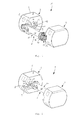
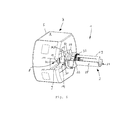
Figuren 1 bis 3 eine perspektivische Darstellung des Hantelsystems, wobei inFigur 1 ein Griff beim Einführen in einen Einsteckschlitz eines Hantelgewichtkörpers, inFigur 2 der Griff in einer Endlage mit dem Hantelgewichtkörper unverriegelt und inFigur 3 der Griff in der Endlage mit dem Hantelgewichtkörper verriegelt gezeigt sind, -
Figuren 4 bis 6 eine teilweise geschnittene perspektivische Darstellung des Hantelsystems, wobei inFigur 4 der Griff in einer Entriegelungsstellung, inFigur 5 der Griff in einer Zwischenstellung und inFigur 6 der Griff in einer Verriegelungsstellung gezeigt ist, -
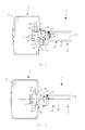
Figuren 7 bis 10 einen Längsschnitt einer Seite des Hantelsystems, wobeiFigur 8 eine Detailvergrößerung ausFigur 7 ist und inFiguren 7 und 8 der Griff in der Entriegelungsstellung, inFigur 9 der Griff in der Zwischenstellung und inFigur 10 der Griff in der Verriegelungsstellung gezeigt sind, -
Figuren 11 bis 13 eine geschnittene perspektivische Darstellung des Hantelsystems, wobei inFigur 11 der Griff in der Entriegelungsstellung, inFigur 12 der Griff in der Zwischenstellung und inFigur 13 der Griff in der Verriegelungsstellung gezeigt ist, -
Figuren 14 und 15 eine teilweise geschnittene perspektivische Darstellung des Hantelsystems, wobeiFigur 15 eine vergrößerte Detaildarstellung ausFigur 14 ist und -
Figuren 16 und 17 eine Teilexplosionsdarstellung des Hantelsystems, wobei inFigur 16 ein Verriegelungsschieber in der Entriegelungsstellung und inFigur 17 der Verriegelungsschieber in der Verriegelungsstellung gezeigt ist. - Wie es aus
Figuren 1 bis 17 ersichtlich ist, weist ein Hantelsystem 1 einen Griff 2 sowie ein erstes Hantelgewicht 3 und ein zweites Hantelgewicht 4 auf. Der Griff 2 ist stabförmig ausgebildet und weist zwei einander abgewandte Längsenden auf, wobei das erste Hantelgewicht 3 an das eine Längsende und das zweite Hantelgewicht 4 an das andere Längsende anbringbar ist. Die beiden Hantelgewichte 3, 4 sind gleich ausgebildet, so dass im Folgenden repräsentativ für die beiden Hantelgewichte 3, 4 lediglich das Hantelgewicht 3 beschrieben ist. - Das Hantelgewicht 3 weist einen Hantelgewichtkörper 5 auf, der zylinderförmig ausgebildet ist. Der Hantelgewichtkörper 5 weist an seiner zylindrisch gewölbten Oberfläche zwei einander abgewandt angeordnete und zueinander parallel verlaufende Abplattungen 6 auf, wodurch der Hantelgewichtkörper 5 beispielsweise auf eine plane Unterlage gestellt werden kann. Ferner ist der Hantelgewichtkörper 5 hohl ausgebildet, wobei im Inneren des Hantelgewichtkörpers 5 ein Hohlraum 7 vorgesehen ist. In den Hohlraum 7 sind wahlweise ein oder mehrere Gewichtselemente unterbringbar, womit durch deren Dimensionierung und Anzahl die Masse des Hantelgewichts 3 bestimmbar ist.
- In etwa parallel zu den Abplattungen 6 verlaufend weist der Hantelgewichtkörper 5 einen Einsteckschlitz 8 auf. Der Einsteckschlitz 8 verläuft an der dem Griff 2 zugewandten Stirnseite des Hantelgewichtkörpers 5 von dessen Außenrad hin zu dessen Mittelpunkt. Der Einsteckschlitz 8 weist zwei einander gegenüberliegende Führungsflanken 9 auf, die im Wesentlichen parallel zu den Abplattungen 6 verlaufen, wobei deren Abstand vom Außenrand des Hantelgewichtkörpers 5 zu dessen Zentrum hin abnimmt, so dass der Einsteckschlitz 8 in Richtung der Zylinderachse des Hantelgewichtkörpers 5 gesehen einen V-förmigen Verlauf hat. Im Zentrum des Hantelgewichtkörpers 5 ist der Einsteckschlitz 8 von einem Schlitzgrund 10 begrenzt, der um die Zylinderachse des Hantelgewichtkörpers 5 eine zylindermantelartigen Form hat. In Schnitten parallel zur Zylinderachse ist der Einsteckschlitz 8 als eine T-Nut ausgebildet, wobei im Inneren des Einsteckschlitzes 8 Hinterschneidungen 11 vorgesehen sind. Außerhalb des Einsteckschlitzes 8 ist in der Nähe des Schlitzgrunds 10 in der Oberfläche des Hantelgewichtkörpers 5 eine Fixieraussparung 12 vorgesehen.
- Um den Schlitzgrund 10 ist in dem Hantelgewichtkörper 5 eine Ringaussparung 13 vorgesehen, die als eine erste Fase 18 ausgebildet ist. Der Schlitzgrund 10 überstreicht einen Winkel von 180°, so dass der Innenrand der ersten Fase 18 ebenfalls den Winkel von 180° überstreicht. Dadurch, dass der Außenrand der ersten Fase 18 radial außerhalb des Schlitzgrunds 10 angeordnet ist, überstreicht der Außenrand der ersten Fase 18 einen Winkel, der größer als 180° ist. Dadurch ergibt sich am Übergang vom Schlitzgrund 10 zu den Führungsflanken 9 ein erster Vorderbereich 15 der ersten Flanke 18 und ein zweiter Vorderbereich 16 der ersten Flanke 18, wobei die Vorderbereiche 15, 16 am Einsteckschlitz 8 einander gegenüberliegend angeordnet sind. Die Vorderbereiche 15, 16 sind mit ihren Fasenflächen den Führungsflanken 9 abgewandt angeordnet, so dass von den Vorderbereichen 15, 16 ein Verriegelungsvorsprung 14 ausgebildet ist. Der Bereich der ersten Fase 18 zwischen den Vorderbereichen 15, 16 ist ein Hinterbereich 17 der ersten Fase 18, an dem benachbart die Fixieraussparung 12 angeordnet ist.
- Der Griff 2 weist eine Achse 19 auf, die an ihren Längsenden jeweils einen Zapfen 20 aufweist. Der Zapfen 20 ist zylinderförmig ausgebildet, dessen Zylinderachse mit der Achslängsrichtung 19 zusammenfällt. Ein Abschnitt der Zylinderoberfläche ist ein Zapfenrücken 21, dem gegenüberliegend ein Exzenter 22 an dem Zapfen 20 angeformt ist und von dem Zapfen 20 radial vorsteht. Der Exzenter 22 weist einen Exzenterrücken 23 auf, der dem Zapfenrücken 21 abgewandt angeordnet ist.
- Ist der Griff 2 an das Hantelgewicht 3 montiert, ist der Zapfen 20 in dem Einsteckschlitz 8 bis zum Schlitzgrund 10 gesteckt. Der Schlitzgrund 10, der Zapfen 20 und der Exzenter 22 sind derart aufeinander abgestimmt dimensioniert, dass der Zapfen 20 mit seinem Zapfenrücken 21 flächig am Schlitzgrund 10 anliegt und der Exzenter 22 mit seinem Exzenterrücken 23 in dem Exzenterschlitz 8 entlang der Führungsflanken 9 sich erstreckt, wobei der Exzenter 22 an den Führungsflanken 9 anliegt.
- Am stirnseitigen freien Ende des Zapfens weist dieser einen Bund 24 auf, der radial von dem Zapfen 20 vorsteht. Ist der Griff 2 an das Hantelgewicht 3 montiert, hintergreift der Bund 24 den Hantelgewichtkörper 5, indem der Bund 24 mit der Hinterschneidung 11 in Eingriff steht. Der Bund 24 weist eine dem Zapfen 20 zugeordnete ringförmige erste Anschlagfläche 25 auf, mit der der Bund 24 an der Hinterschneidung anstößt, wenn der Zapfen 20 axial aus dem Einsteckschlitz 8 gezogen wird.
- In dem Zapfen 20 ist ein Gerätehohlraum 26 vorgesehen, der zum Zapfenrücken 21 hin nach außen offen ist. In dem Gerätehohlraum 26 kann beispielsweise ein optisches Sensorinstrument untergebracht sein, mit dem eine an entsprechender Stelle am Schlitzgrund 10 angebrachte Markierung abgetastet werden kann. Mit der Markierung ist beispielsweise angezeigt, wie schwer das Hantelgewicht 3 ist, so dass beispielsweise mit dem Sensorinstrument eine Überwachung der Bestückung des Griffs 2 mit dem Hantelgewicht 3 bewerkstelligbar ist.
- Der Griff 2 weist ferner ein Griffrohr 27 auf, in dem konzentrisch die Achse 19 angeordnet ist. Die Außenseite des Griffrohrs 27 ist gebildet von einer Grifffläche 28, mit der der Griff angefasst werden kann. In der Nähe ihrer Längsenden weist das Griffrohr 27 jeweils einen Antriebsstift 29 auf, der an dem Griffrohr 27 befestigt ist und radial nach innen sich erstreckt. Außerdem bildet jede Stirnseite des Griffrohrs 27 jeweils eine zweite Anschlagfläche 30, an der der Hantelgewichtkörper 5 abgestützt ist, wenn das Hantelgewicht 3 an dem Griff 2 montiert ist. Die erste Anschlagfläche 25 des Bunds 24 und die zweite Anschlagfläche 30 des Griffrohrs 27 sind im Axialabstand derart voneinander angeordnet, dass zwischen den Anschlagflächen 25, 30 der Hantelgewichtkörper 5 in Achslängsrichtung fixiert ist. Denkbar ist, dass beispielsweise in der ersten Anschlagfläche 25 und/oder der zweiten Anschlagfläche 30 eine Ringnut vorgesehen ist, in der beispielsweise ein elastisches Material, wie beispielsweise Gummi, eingebracht ist, wodurch das Fixieren des Hantelgewichtkörpers 5 mit den Anschlagflächen 25, 30 unter einer Vorspannung hervorgerufen durch das elastische Material bewerkstelligt ist. Dadurch ist ein Spiel zwischen den Anschlagflächen 25, 30 und dem Hantelgewichtkörper 5 überbrückt, wobei der Hantelgewichtkörper 5 spielfrei in Achslängsrichtung an dem Griff 2 montierbar ist. Dadurch, dass das elastische Material nachgeben kann, ist dennoch eine einfach handhabbare Montage des Hantelgewichts 3 an den Griff 2 ermöglicht.
- An der Außenseite des Griffrohrs 27 ist jeweils an ihrer Stirnseite ein vorgespannter Riegelstein 31 vorgesehen, der derart auf die Fixieraussparung 12 abgestimmt dimensioniert und angeordnet ist, dass, wenn der Griff 2 in seiner Montageposition ist, der Riegelstein 31 vorgespannt in die Fixieraussparung 12 eingreift. Dadurch ist durch den von dem Riegelstein 31 in der Fixieraussparung 12 ausgebildeten Formschluss das Griffrohr 27 gegen das Verdrehen relativ zu dem Hantelgewichtkörper 5 verriegelt. Der Riegelstein 31 steht von der Verriegelungsaussparung 12 axial vor und ist von außerhalb des Griffrohrs 27 zugänglich, so dass der Riegelstein 31 entgegen seiner Vorspannung aus der Fixieraussparung 12 gedrückt werden kann, wodurch die Drehverriegelung des Griffrohrs 27 relativ zu dem Hantelgewichtkörper 5 wieder aufgehoben ist.
- Der Griff 2 weist eine Rückstellfeder 32 auf, die sowohl an dem Griffrohr 27 als auch an der Achse 19 angreift und derart vorgespannt ist, dass die Rückstellfeder 32 den Demontagevorgang des Griffs 2 von dem Hantelgewicht 3 unterstützt.
- Außerdem weist der Griff 2 einen Verriegelungsschieber 33 auf, der als eine Hülse ausgebildet ist, und jeweils an den Längsenden des Griffs 2 vorgesehen ist. Der Verriegelungsschieber 33 ist über den Zapfen 20 und über die Achse 19 verschiebbar angeordnet, wobei der Verriegelungsschieber 33 an seiner dem freien Längsende der Achse 19 zugewandten Seite eine Verriegelungsfront 34 aufweist. Die Verriegelungsfront 34 ist als eine zweite Fase 35 ausgebildet, die als Gegenstück zur ersten Fase 18 dimensioniert ist. Zwischen dem Verriegelungsschieber 33 und der Achse 19 ist ein Linearlager 36 vorgesehen, mit dem der Verriegelungsschieber 33 in Achslängsrichtung längsverschiebbar aber verdrehfest auf der Achse 19 gelagert ist. Der Verriegelungsschieber 33 weist in seiner zylindrischen Außenseite eine Kulisse 37 auf, die gewindegangartig in dem Verriegelungsschieber 33 sich erstreckt, wobei in die Kulisse 37 der Antriebsstift 29 eingereift. Die Kulisse 37 weist an ihrem einen Ende einen ersten Kulissenbereich 38 und an ihrem anderen Ende einen zweiten Kulissenbereich 39, wobei der erste Kulissenbereich 38 zu dem benachbarten Längsende der Achse 19 zugewandt und der zweite Kulissenbereich 39 dem benachbarten Längsende der Achse 19 abgewandt angeordnet ist. Die Steigung des gewindegangartigen Verlaufs der Kulisse 37 ist im ersten Kulissenbereich 38 größer als im zweiten Kulissenbereich 39.
- Im Folgenden wird die Montage des Griffs an das Hantelgewicht 3 beschrieben. Als Ausgangslage ist der Griff 2 von dem Hantelgewicht 3 räumlich getrennt. Der Griff 2 ist mit der Hand an der Grifffläche 28 zu fassen, wobei das Hantelgewicht 3 auf seine Abplattung 6 gestellt bereitsteht. Der Griff 2 ist horizontal an das Hantelgewicht 3 hinzuführen, wobei die Achslängsrichtung mit der Zylinderachse des Hantelgewichtkörpers 5 parallel ist. Der Griff 2 ist am Außenrand des Hantelgewichtkörpers 5 an den Einsteckschlitz 8 heranzuführen, wobei der Zapfen 20 in den Einsteckschlitz 8 derart eingeführt wird, dass der Bund 24 hinter die Hinterschneidungen 11 greift und dass der Exzenter 22 den Schlitzgrund 10 abgewandt geordnet ist. Parallel zu den Führungsflanken 9 verlaufend ist der Griff 2 in seine Endlage zu bringen, in der der Zapfenrücken 21 an dem Schlitzgrund 10 anliegt. In der Endlage fallen im Wesentlichen die Längsachse der Achse 19 mit der Zylinderachse des Hantelgewichtkörpers 5 zusammen. Der Riegelstein 31 steht mit der Fixieraussparung 12 außer Eingriff.
- Der Verriegelungsschieber 33 ist in einer Entriegelungsstellung, bei der der Verriegelungsschieber 33 seinen maximal möglichen Axialabstand von dem Hantelgewichtkörper 5 hat, wobei der Antriebsstift 29 im ersten Kulissenbereich 38 in die Kulisse 37 eingreift. Der Hantelgewichtkörper 5 ist durch die formschlüssige Verbindung zwischen den Anschlagflächen 25 und 30 zusammen mit den Hinterschneidungen 11 in Achslängsrichtung festgelegt. Die Rückstellfeder 32 spannt das Griffrohr 27 gegenüber der Achse 19 derart vor, dass der Antriebsstift 29 in den ersten Kulissenbereich 38 der Kulisse 37 gedrückt wird und somit die Verdrehposition des Griffrohrs 27 stabilisiert ist.
- Zum Abschluss der Montage ist der Verriegelungsschieber 33 von seiner Entriegelungsstellung in seine Verriegelungsstellung zu bringen. Dies ist durch manuelles Verdrehen des Griffrohrs 27 in die Drehrichtung zu bewerkstelligen, die aufgrund des Anschlags des Antriebsstifts 29 in dem Kulissenbereich 38 freigegeben ist. Beim Verdrehen des Griffrohrs 27 in diese Drehrichtung ist gegen die Vorspannung der Rückstellfeder 32 zu arbeiten. Beim Verdrehen des Griffrohrs 27 durchwandert der Antriebsstift 29 die Kulisse 37 von der Entriegelungsstellung in eine Zwischenstellung und schließlich in eine Verriegelungsstellung, in der der Antriebsstift 29 im zweiten Kulissenbereich 39 angeordnet ist. In der Verriegelungsstellung kann der Antriebsstift 29 im zweiten Kulissenbereich 39 an die Kulisse 37 anstoßen. Beim Gelangen von der Entriegelungsstellung via die Zwischenstellung in die Verriegelungsstellung rotiert der Antriebsstift 29 von dem Griffrohr 27 angetrieben um die Achse 19, wobei durch das Zusammenwirken des Antriebsstifts 29 und der Kulisse 37 und deren gewindegangartigem Verlauf der Verriegelungsschieber 33 in Richtung zu dem Hantelgewichtkörper 5 verschoben wird. Dabei wird von dem Linearlager 36 der Verriegelungsschieber 33 verdrehfest auf der Achse 19 gehalten. Beim Verschieben des Verriegelungsschiebers 33 von der Entriegelungsstellung zu der Verriegelungsstellung berührt die zweite Fase 35 des Verriegelungsschiebers 33 die erste Fase 18 des Hantelgewichtkörpers 5. Wird schließlich der Verriegelungsschieber 33 in die Verriegelungsstellung gebracht, greift der Verriegelungsschieber 33 mit seiner zweiten Fase 35 immer mehr in die Ringaussparung 13 mit ihrer ersten Fase 18 ein, wodurch der Griff 2 mit dem Verriegelungsschieber 33 an dem Hantelgewichtkörper 5 unter Zusammenwirken der Fasen 18, 35 zentriert wird. Dadurch, dass der Verriegelungsschieber mit seiner Verriegelungsfront 34 in die Ringaussparung 33 eingreift, wird mit den Vorderbereichen 15, 16 des Verriegelungsvorsprungs 14 der Ringaussparung 13 eine formschlüssige Verbindung ausgebildet, durch die eine Bewegung des Griffs 2 weg von dem Schlitzgrund 10 versperrt ist. Beim Verdrehen des Griffrohrs 27, so dass der Verriegelungsschieber 33 von der Entriegelungsstellung in die Verriegelungsstellung gebracht wird, ist die Achse 19 durch ein Anlegen des Exzenters 22 an eine der Führungsflanken 9 des Einsteckschlitzes 8 relativ zum Hantelgewichtkörper 5 verdrehfest gehalten. Sobald der Verriegelungsschieber 33 in der Verriegelungsstellung ist, ist der Riegelstein 31 an der Fixieraussparung 12 derart angeordnet, dass der Riegelstein 31 durch seine Vorspannung in die Fixieraussparung 12 getrieben wird und in diese eingreift. Dadurch ist das Griffrohr 27 gegen ein Verdrehen relativ zum Hantelgewichtkörper 5 verriegelt.
- Zum Demontieren des Griffs 2 von dem Hantelgewicht 3 ist wie folgt vorzugehen. Der Riegelstein 31 ist entgegen seiner Vorspannung aus der Fixieraussparung 12 zu bringen, so dass der Riegelstein 31 nicht mehr mit der Fixieraussparung 12 in Eingriff steht. Dadurch ist das Verdrehen des Griffrohrs 27 relativ zur Achse 19 und zum Hantelgewichtkörper 5 freigegeben. Das Griffrohr 27 ist manuell so weit zu verdrehen, bis der Antriebsstift 29 im ersten Kulissenbereich 38 an die Kulisse 37 anstößt. Dabei wird der Verriegelungsschieber 33 aus der Verriegelungsstellung in die Entriegelungsstellung geschoben, wodurch der Verriegelungsschieber 33 außer Eingriff mit der Ringaussparung 13 gebracht wird. Dadurch ist die formschlüssige Verbindung zwischen dem Verriegelungsschieber 33 und dem Verriegelungsvorsprung 14 aufgelöst, wodurch der Griff 2 einen Freiheitsgrad entlang der Führungsflanken 9 des Einsteckschlitzes 8 weg von dem Schlitzgrund 10 hat. Somit kann der Griff 2 aus dem Einsteckschlitz 8 herausgenommen und von dem Hantelgewicht 3 demontiert werden.
-
- 1
- Hantelsystem
- 2
- Griff
- 3
- erstes Hantelgewicht
- 4
- zweites Hantelgewicht
- 5
- Hantelgewichtkörper
- 6
- Abplattung
- 7
- Hohlraum
- 8
- Einsteckschlitz
- 9
- Führungsflanke
- 10
- Schlitzgrund
- 11
- Hinterschneidung
- 12
- Fixieraussparung
- 13
- Ringsaussparung
- 14
- Verriegelungsvorsprung
- 15
- erster Vorderbereich
- 16
- zweiter Vorderbereich
- 17
- Hinterbereich
- 18
- erste Fase
- 19
- Achse
- 20
- Zapfen
- 21
- Zapfenrücken
- 22
- Exzenter
- 23
- Exzenterrücken
- 24
- Bund
- 25
- erste Anschlagfläche
- 26
- Geräthohlraum
- 27
- Griffrohr
- 28
- Grifffläche
- 29
- Antriebsstift
- 30
- zweite Anschlagfläche
- 31
- Riegelsrein
- 32
- Rückstellfeder
- 33
- Verriegelungsschieber
- 34
- Verriegelungsfront
- 35
- zweite Fase
- 36
- Linearlager
- 37
- Kulisse
- 38
- erster Kulissenbereich
- 39
- zweiter Kulissenbereich
Claims (16)
- Hantelsystem mit mindestens einem Hantelgewicht (3, 4) und einem Griff (2), der eine Achse (19) und ein konzentrisch um die Achse (19) sowie um diese verdrehbar angeordnetes Griffrohr (27) aufweist, von dem in Achslängsrichtung die Achse (19) mit einem einen Exzenter (22) aufweisenden Zapfen (20) vorsteht, wobei das Hantelgewicht (3, 4) einen Hantelgewichtkörper (5) aufweist, in dem ein Einsteckschlitz (8) geformt ist, der sich vom Rand des Hantelgewichtkörpers (5) bis zu dessen Zentrumsbereich erstreckt, an dem ein Verriegelungsvorsprung (14) angeformt und in dem von einem Schlitzgrund (10) der Einsteckschlitz (8) begrenzt ist, der auf den Zapfen (20) derart abgestimmt geformt ist, dass der Zapfen (20) am Rand des Hantelgewichts (3, 4) mit dem Einsteckschlitz (8) in Eingriff bringbar und bis zum Schlitzgrund (10) quer zur Achslängsrichtung verschiebbar und am Schlitzgrund (10) angeordnet sowie von dem Exzenter (22) formschlüssig verdrehfest in eine Endlage bringbar ist, und wobei der Griff (2) einen Verriegelungsschieber (33) und ein Getriebe (36) aufweist, mit dem der Verriegelungsschieber (33) mit der Achse (19) und dem Griffrohr (27) derart gekoppelt ist, dass durch Verdrehen des Griffrohrs (27) relativ zur Achse (19) der Verriegelungsschieber (33) längsverschiebbar und dadurch in eine Entriegelungsstellung, in der der Verriegelungsschieber (33) mit dem Verriegelungsvorsprung (14) außer Eingriff steht, und in eine Verriegelungsstellung bringbar ist, in der der Verriegelungsschieber (33) mit dem Verriegelungsvorsprung (14) derart in Eingriff steht, dass der Zapfen (20) von dem Verriegelungsvorsprung (33) via den Verriegelungsschieber (33) zusammen mit dem Schlitzgrund (10) quer zur Achslängsrichtung gehalten ist, wodurch das Hantelgewicht (3, 4) an den Griff (2) lösbar festlegbar ist durch ein Verdrehen des Griffrohrs (27) relativ zu dem Hantelgewichtkörper (5).
- Hantelsystem gemäß Anspruch 1, wobei der Verriegelungsvorsprung (14) zum InEingriffstehen mit dem Verriegelungsschieber (33) von einer ersten Fase (18) des Hantelgewichtkörpers (5) um den Schlitzgrund (10) gebildet ist, der den Zapfen (20) in dessen Endlage um 180° C-förmig umgreift.
- Hantelsystem gemäß Anspruch 2, wobei der Verriegelungsschieber (33) als eine Hülse ausgebildet ist, die zwischen dem Griffrohr (27) und der Achse (19) sowie zu dieser konzentrisch angeordnet ist.
- Hantelsystem gemäß Anspruch 3, wobei in der Verriegelungsstellung der Verriegelungsschieber (33) mit der ersten Fase (18) in Eingriff steht und der Verriegelungsschieber (33) zumindest teilweise über den Zapfen (10) geschoben ist.
- Hantelsystem gemäß einem der Ansprüche 1 bis 4, wobei der Verriegelungsschieber (33) zum InEingriffstehen mit dem Verriegelungsvorsprung (14) eine mit diesem zusammenwirkende und stirnseitig angeordnete zweite Fase (35) aufweist.
- Hantelsystem gemäß einem der Ansprüche 1 bis 5, wobei das Getriebe einen Gewindetrieb (29, 37) aufweist, mit dem das Griffrohr (27) mit dem Verriegelungsschieber (33) gekoppelt ist, so dass eine Verdrehung relativ zur Achse des Griffrohrs (27) in eine Längsbewegung des Verriegelungsschiebers (33) in die Achslängsrichtung übersetzbar ist.
- Hantelsystem gemäß Anspruch 6, wobei der Gewindetrieb einen an der Innenseite des Griffrohrs (27) befestigten und radial sich erstreckenden Antriebsstift (29) und der Verriegelungsschieber (33) eine gewindegangartig verlaufende Kulisse (37) aufweist, mit der der Antriebsstift (29) in Eingriff steht, so dass beim Verdrehen des Griffrohrs (27) der Antriebsstift (29) den Verriegelungsschieber (33) via die Kulisse (37) mitnimmt.
- Hantelsystem gemäß Anspruch 7, wobei die Kulisse (37) einen ersten Kulissenbereich (38), in dem der Antriebsstift (29) angeordnet ist, wenn der Verriegelungsschieber (33) in der Entriegelungsstellung angeordnet ist, und einen zweiten Kulissenbereich (39) aufweist, in dem der Antriebsstift (29) angeordnet ist, wenn der Verriegelungsschieber (33) in der Verriegelungsstellung angeordnet ist, wobei sie Steigung der Kulisse (37) im ersten Kulissenbereich (38) höher ist als im zweiten Kulissenbereich (39).
- Hantelsystem gemäß einem der Ansprüche 1 bis 8, wobei das Getriebe ein Linearlager (36) aufweist, mit dem der Verriegelungsschieber (33) mit der Achse (19) verdrehstarr und in die Achslängsrichtung verschiebbar gekoppelt ist.
- Hantelsystem gemäß einem der Ansprüche 1 bis 9, wobei der Einsteckschlitz (8) sich von dem Schlitzgrund (10) zum Rand des Hantelgewichtkörpers (5) V-förmig öffnet.
- Hantelsystem gemäß Anspruch 10, wobei der Exzenter (22) an einer dem Zapfenzentrum abgewandten Seite dicker als der Zapfen (20) ist sowie der Einsteckschlitz (8) am Schlitzgrund (10) im wesentlichen eine Weite hat, die der Dicke des Zapfens (20) entspricht, so dass in der Endlage des Zapfens (20) der Exzenter (22) dem Schlitzgrund (10) abgewandt angeordnet ist.
- Hantelsystem gemäß einem der Ansprüche 1 bis 11, wobei der Hantelgewichtkörper (5) eine Abplattung (6) aufweist, mit der das Hantelgewicht (3, 4) bei einer Verdrehbetätigung des Griffrohrs (27) verdrehfest auf eine Unterlage ablegbar ist.
- Hantelsystem gemäß einem der Ansprüche 1 bis 12, wobei der Zapfen (20) einen dem Verriegelungsschieber (33) abgewandt angeordneten Bund (24) aufweist und der Hantelgewichtkörper (5) auf den Bund (24) abgestimmt derart geformt ist, dass der Hantelgewichtkörper (5) zwischen dem Bund (24) und dem Verriegelungsschieber (33), wenn dieser in der Verriegelungsstellung ist, in Achslängsrichtung festgelegt ist.
- Hantelsystem gemäß einem der Ansprüche 1 bis 13, wobei das Hantelsystem (1) eine Fixiereinrichtung (12, 31) aufweist, mit der der Hantelgewichtkörper (5), wenn der Verriegelungsschieber (33) in der Verriegelungsstellung ist, an dem Griffrohr (27) von außen lösbar verdrehfest fixierbar ist.
- Hantelsystem gemäß einem der Ansprüche 1 bis 14, wobei der Hantelgewichtkörper (5) einen Hohlraum (7) aufweist, der mit einem vorherbestimmten Gewichtelement bestückt ist.
- Hantelsystem gemäß Anspruch 15, wobei das Hantelsystem (1) eine Mehrzahl an Hantelgewichten aufweist, die jeweils mit unterschiedlich schweren Gewichtselementen bestückt sind, so dass mindestens ein aus der Mehrzahl der Hantelgewichte (3, 4) vorherbestimmtes Hantelgewicht (3, 4) an den Griff (2) unter Verdrehbetätigung des Griffrohrs (27) lösbar festlegbar ist.
Priority Applications (2)
| Application Number | Priority Date | Filing Date | Title |
|---|---|---|---|
| EP11183307.5A EP2574376B1 (de) | 2011-09-29 | 2011-09-29 | Hantelsystem mit Hantelgewichten und einem Griff |
| PCT/EP2012/069286 WO2013045677A1 (de) | 2011-09-29 | 2012-09-28 | Hantelsystem mit hantelgewichten und einem griff |
Applications Claiming Priority (1)
| Application Number | Priority Date | Filing Date | Title |
|---|---|---|---|
| EP11183307.5A EP2574376B1 (de) | 2011-09-29 | 2011-09-29 | Hantelsystem mit Hantelgewichten und einem Griff |
Publications (2)
| Publication Number | Publication Date |
|---|---|
| EP2574376A1 true EP2574376A1 (de) | 2013-04-03 |
| EP2574376B1 EP2574376B1 (de) | 2016-05-11 |
Family
ID=44719572
Family Applications (1)
| Application Number | Title | Priority Date | Filing Date |
|---|---|---|---|
| EP11183307.5A Not-in-force EP2574376B1 (de) | 2011-09-29 | 2011-09-29 | Hantelsystem mit Hantelgewichten und einem Griff |
Country Status (2)
| Country | Link |
|---|---|
| EP (1) | EP2574376B1 (de) |
| WO (1) | WO2013045677A1 (de) |
Cited By (2)
| Publication number | Priority date | Publication date | Assignee | Title |
|---|---|---|---|---|
| CN114011010A (zh) * | 2021-12-01 | 2022-02-08 | 江苏万喜至工业设计有限公司 | 双联手抓自动增减重块式哑铃 |
| GB2599077A (en) * | 2020-09-09 | 2022-03-30 | Fluvial Innovations Ltd | Exercise weight |
Families Citing this family (2)
| Publication number | Priority date | Publication date | Assignee | Title |
|---|---|---|---|---|
| CN104826276B (zh) * | 2015-05-14 | 2017-09-01 | 苏州桀勇不锈钢制品有限公司 | 一种混沌摆哑铃 |
| CN107970561B (zh) * | 2017-12-28 | 2022-11-08 | 南通安客体育用品有限公司 | 一种健身锻炼设备及其组件和相关方法 |
Citations (3)
| Publication number | Priority date | Publication date | Assignee | Title |
|---|---|---|---|---|
| US20050277525A1 (en) * | 2004-06-10 | 2005-12-15 | Liu Wei M | Weight lifting device having selector device |
| US20080026921A1 (en) * | 2006-07-27 | 2008-01-31 | Ping Liu | Adjustable dumbbell system |
| GB2468857A (en) * | 2009-03-24 | 2010-09-29 | Paul Chen | Weight adjustable exercise device |
-
2011
- 2011-09-29 EP EP11183307.5A patent/EP2574376B1/de not_active Not-in-force
-
2012
- 2012-09-28 WO PCT/EP2012/069286 patent/WO2013045677A1/de not_active Ceased
Patent Citations (3)
| Publication number | Priority date | Publication date | Assignee | Title |
|---|---|---|---|---|
| US20050277525A1 (en) * | 2004-06-10 | 2005-12-15 | Liu Wei M | Weight lifting device having selector device |
| US20080026921A1 (en) * | 2006-07-27 | 2008-01-31 | Ping Liu | Adjustable dumbbell system |
| GB2468857A (en) * | 2009-03-24 | 2010-09-29 | Paul Chen | Weight adjustable exercise device |
Cited By (3)
| Publication number | Priority date | Publication date | Assignee | Title |
|---|---|---|---|---|
| GB2599077A (en) * | 2020-09-09 | 2022-03-30 | Fluvial Innovations Ltd | Exercise weight |
| GB2599077B (en) * | 2020-09-09 | 2024-10-02 | Fluvial Innovations Ltd | Exercise weight |
| CN114011010A (zh) * | 2021-12-01 | 2022-02-08 | 江苏万喜至工业设计有限公司 | 双联手抓自动增减重块式哑铃 |
Also Published As
| Publication number | Publication date |
|---|---|
| EP2574376B1 (de) | 2016-05-11 |
| WO2013045677A1 (de) | 2013-04-04 |
Similar Documents
| Publication | Publication Date | Title |
|---|---|---|
| EP2054110B1 (de) | Injektionsvorrichtung mit mechanikverriegelung | |
| DE60106980T2 (de) | Hebelbetätigter Verschluss für Teleskopstange | |
| DE202019101385U1 (de) | Drehmomentwerkzeug mit einer Anordnung zur Erkennung des Ver- bzw. Entriegelungszustandes einer Einrichtung zur Drehmomenteinstellung | |
| EP0271782B1 (de) | Federnspanner | |
| DE202004015990U1 (de) | Chirurgisches Stanzinstrument | |
| DE202004021288U1 (de) | Höhenverstellbares Implantat zum Einsetzen zwischen Wirbelkörpern und Handhabungswerkzeug | |
| DE112009001844T5 (de) | Terminkalendersynchronisierung für Smartphone-Anwendungen | |
| EP1922004A1 (de) | Schraubendreher für knochenschrauben | |
| EP0521490B1 (de) | Anordnung aus zwei teleskopisch miteinander verbundenen Bauelementen | |
| EP2574376B1 (de) | Hantelsystem mit Hantelgewichten und einem Griff | |
| DE102014116705B4 (de) | Laborrührer | |
| DE102013225594A1 (de) | Arretierbolzen-Anordnung mit kappenartigem Drehknopf | |
| EP2861890B1 (de) | Verstellvorrichtung für ein fahrwerk eines fahrzeugs | |
| EP2704929B1 (de) | Arretiermechanismus | |
| DE112009001858T5 (de) | Tightening Device With Cam Lever | |
| DE202013105249U1 (de) | Elektromotorischer Linearantrieb | |
| DE4441019C2 (de) | Wellenkupplung | |
| EP2784192A1 (de) | Auflösewalze mit Drehverschluss und Sicherungselement | |
| DE69831970T2 (de) | Übertragungsvorrichtung und einstellbarer fahrradlenker mit einer solchen vorrichtung | |
| DE102011103337A1 (de) | Betätigungsvorrichtung zur An- oder Auskupplung einer Antriebswelle an oder von einem Antriebsstrang | |
| DE3205133A1 (de) | Vorrichtung zur winkelverstellung der rueckenlehne eines sitzes, insbesondere kraftfahrzeugsitzes | |
| DE202006014177U1 (de) | Vorrichtung zum Ausziehen eines in einer Bohrung eines Bauteils sitzenden Bauelements | |
| DE2244222C3 (de) | Umschalteinrichtung für den Freilauf eines Schraubwerkzeugs mit Ratsche, insbesondere für einen Schraubendreher | |
| DE1920743C3 (de) | Antrieb mittels biegsamer Welle fur auswechselbare Dentalwerkzeuge | |
| DE4142201A1 (de) | Muttern- bzw. schraubenschluessel mit ratschenfunktion |
Legal Events
| Date | Code | Title | Description |
|---|---|---|---|
| PUAI | Public reference made under article 153(3) epc to a published international application that has entered the european phase |
Free format text: ORIGINAL CODE: 0009012 |
|
| AK | Designated contracting states |
Kind code of ref document: A1 Designated state(s): AL AT BE BG CH CY CZ DE DK EE ES FI FR GB GR HR HU IE IS IT LI LT LU LV MC MK MT NL NO PL PT RO RS SE SI SK SM TR |
|
| AX | Request for extension of the european patent |
Extension state: BA ME |
|
| RAP1 | Party data changed (applicant data changed or rights of an application transferred) |
Owner name: BEIER, JUERGEN |
|
| 17P | Request for examination filed |
Effective date: 20140115 |
|
| RBV | Designated contracting states (corrected) |
Designated state(s): AL AT BE BG CH CY CZ DE DK EE ES FI FR GB GR HR HU IE IS IT LI LT LU LV MC MK MT NL NO PL PT RO RS SE SI SK SM TR |
|
| RAP1 | Party data changed (applicant data changed or rights of an application transferred) |
Owner name: MAYR, FICHTNER, FICHTNER, BEHR GBR |
|
| REG | Reference to a national code |
Ref country code: DE Ref legal event code: R079 Ref document number: 502011009706 Country of ref document: DE Free format text: PREVIOUS MAIN CLASS: A63B0021072000 Ipc: A63B0021075000 |
|
| GRAP | Despatch of communication of intention to grant a patent |
Free format text: ORIGINAL CODE: EPIDOSNIGR1 |
|
| RIC1 | Information provided on ipc code assigned before grant |
Ipc: A63B 21/075 20060101AFI20140331BHEP Ipc: A63B 21/072 20060101ALI20140331BHEP |
|
| INTG | Intention to grant announced |
Effective date: 20140505 |
|
| GRAS | Grant fee paid |
Free format text: ORIGINAL CODE: EPIDOSNIGR3 |
|
| GRAA | (expected) grant |
Free format text: ORIGINAL CODE: 0009210 |
|
| AK | Designated contracting states |
Kind code of ref document: B1 Designated state(s): AL AT BE BG CH CY CZ DE DK EE ES FI FR GB GR HR HU IE IS IT LI LT LU LV MC MK MT NL NO PL PT RO RS SE SI SK SM TR |
|
| REG | Reference to a national code |
Ref country code: GB Ref legal event code: FG4D Free format text: NOT ENGLISH |
|
| REG | Reference to a national code |
Ref country code: CH Ref legal event code: EP |
|
| REG | Reference to a national code |
Ref country code: AT Ref legal event code: REF Ref document number: 798175 Country of ref document: AT Kind code of ref document: T Effective date: 20160515 |
|
| REG | Reference to a national code |
Ref country code: IE Ref legal event code: FG4D Free format text: LANGUAGE OF EP DOCUMENT: GERMAN |
|
| REG | Reference to a national code |
Ref country code: DE Ref legal event code: R096 Ref document number: 502011009706 Country of ref document: DE |
|
| REG | Reference to a national code |
Ref country code: LT Ref legal event code: MG4D |
|
| REG | Reference to a national code |
Ref country code: NL Ref legal event code: MP Effective date: 20160511 |
|
| PG25 | Lapsed in a contracting state [announced via postgrant information from national office to epo] |
Ref country code: NO Free format text: LAPSE BECAUSE OF FAILURE TO SUBMIT A TRANSLATION OF THE DESCRIPTION OR TO PAY THE FEE WITHIN THE PRESCRIBED TIME-LIMIT Effective date: 20160811 Ref country code: LT Free format text: LAPSE BECAUSE OF FAILURE TO SUBMIT A TRANSLATION OF THE DESCRIPTION OR TO PAY THE FEE WITHIN THE PRESCRIBED TIME-LIMIT Effective date: 20160511 Ref country code: NL Free format text: LAPSE BECAUSE OF FAILURE TO SUBMIT A TRANSLATION OF THE DESCRIPTION OR TO PAY THE FEE WITHIN THE PRESCRIBED TIME-LIMIT Effective date: 20160511 Ref country code: FI Free format text: LAPSE BECAUSE OF FAILURE TO SUBMIT A TRANSLATION OF THE DESCRIPTION OR TO PAY THE FEE WITHIN THE PRESCRIBED TIME-LIMIT Effective date: 20160511 |
|
| PG25 | Lapsed in a contracting state [announced via postgrant information from national office to epo] |
Ref country code: SE Free format text: LAPSE BECAUSE OF FAILURE TO SUBMIT A TRANSLATION OF THE DESCRIPTION OR TO PAY THE FEE WITHIN THE PRESCRIBED TIME-LIMIT Effective date: 20160511 Ref country code: RS Free format text: LAPSE BECAUSE OF FAILURE TO SUBMIT A TRANSLATION OF THE DESCRIPTION OR TO PAY THE FEE WITHIN THE PRESCRIBED TIME-LIMIT Effective date: 20160511 Ref country code: LV Free format text: LAPSE BECAUSE OF FAILURE TO SUBMIT A TRANSLATION OF THE DESCRIPTION OR TO PAY THE FEE WITHIN THE PRESCRIBED TIME-LIMIT Effective date: 20160511 Ref country code: GR Free format text: LAPSE BECAUSE OF FAILURE TO SUBMIT A TRANSLATION OF THE DESCRIPTION OR TO PAY THE FEE WITHIN THE PRESCRIBED TIME-LIMIT Effective date: 20160812 Ref country code: PT Free format text: LAPSE BECAUSE OF FAILURE TO SUBMIT A TRANSLATION OF THE DESCRIPTION OR TO PAY THE FEE WITHIN THE PRESCRIBED TIME-LIMIT Effective date: 20160912 Ref country code: ES Free format text: LAPSE BECAUSE OF FAILURE TO SUBMIT A TRANSLATION OF THE DESCRIPTION OR TO PAY THE FEE WITHIN THE PRESCRIBED TIME-LIMIT Effective date: 20160511 Ref country code: HR Free format text: LAPSE BECAUSE OF FAILURE TO SUBMIT A TRANSLATION OF THE DESCRIPTION OR TO PAY THE FEE WITHIN THE PRESCRIBED TIME-LIMIT Effective date: 20160511 |
|
| PG25 | Lapsed in a contracting state [announced via postgrant information from national office to epo] |
Ref country code: IT Free format text: LAPSE BECAUSE OF FAILURE TO SUBMIT A TRANSLATION OF THE DESCRIPTION OR TO PAY THE FEE WITHIN THE PRESCRIBED TIME-LIMIT Effective date: 20160511 |
|
| PG25 | Lapsed in a contracting state [announced via postgrant information from national office to epo] |
Ref country code: DK Free format text: LAPSE BECAUSE OF FAILURE TO SUBMIT A TRANSLATION OF THE DESCRIPTION OR TO PAY THE FEE WITHIN THE PRESCRIBED TIME-LIMIT Effective date: 20160511 Ref country code: SK Free format text: LAPSE BECAUSE OF FAILURE TO SUBMIT A TRANSLATION OF THE DESCRIPTION OR TO PAY THE FEE WITHIN THE PRESCRIBED TIME-LIMIT Effective date: 20160511 Ref country code: RO Free format text: LAPSE BECAUSE OF FAILURE TO SUBMIT A TRANSLATION OF THE DESCRIPTION OR TO PAY THE FEE WITHIN THE PRESCRIBED TIME-LIMIT Effective date: 20160511 Ref country code: CZ Free format text: LAPSE BECAUSE OF FAILURE TO SUBMIT A TRANSLATION OF THE DESCRIPTION OR TO PAY THE FEE WITHIN THE PRESCRIBED TIME-LIMIT Effective date: 20160511 Ref country code: EE Free format text: LAPSE BECAUSE OF FAILURE TO SUBMIT A TRANSLATION OF THE DESCRIPTION OR TO PAY THE FEE WITHIN THE PRESCRIBED TIME-LIMIT Effective date: 20160511 |
|
| REG | Reference to a national code |
Ref country code: DE Ref legal event code: R097 Ref document number: 502011009706 Country of ref document: DE |
|
| PG25 | Lapsed in a contracting state [announced via postgrant information from national office to epo] |
Ref country code: SM Free format text: LAPSE BECAUSE OF FAILURE TO SUBMIT A TRANSLATION OF THE DESCRIPTION OR TO PAY THE FEE WITHIN THE PRESCRIBED TIME-LIMIT Effective date: 20160511 Ref country code: PL Free format text: LAPSE BECAUSE OF FAILURE TO SUBMIT A TRANSLATION OF THE DESCRIPTION OR TO PAY THE FEE WITHIN THE PRESCRIBED TIME-LIMIT Effective date: 20160511 Ref country code: BE Free format text: LAPSE BECAUSE OF NON-PAYMENT OF DUE FEES Effective date: 20160930 |
|
| PLBE | No opposition filed within time limit |
Free format text: ORIGINAL CODE: 0009261 |
|
| STAA | Information on the status of an ep patent application or granted ep patent |
Free format text: STATUS: NO OPPOSITION FILED WITHIN TIME LIMIT |
|
| REG | Reference to a national code |
Ref country code: DE Ref legal event code: R119 Ref document number: 502011009706 Country of ref document: DE |
|
| 26N | No opposition filed |
Effective date: 20170214 |
|
| PG25 | Lapsed in a contracting state [announced via postgrant information from national office to epo] |
Ref country code: MC Free format text: LAPSE BECAUSE OF FAILURE TO SUBMIT A TRANSLATION OF THE DESCRIPTION OR TO PAY THE FEE WITHIN THE PRESCRIBED TIME-LIMIT Effective date: 20160511 |
|
| REG | Reference to a national code |
Ref country code: CH Ref legal event code: PL |
|
| GBPC | Gb: european patent ceased through non-payment of renewal fee |
Effective date: 20160929 |
|
| PG25 | Lapsed in a contracting state [announced via postgrant information from national office to epo] |
Ref country code: SI Free format text: LAPSE BECAUSE OF FAILURE TO SUBMIT A TRANSLATION OF THE DESCRIPTION OR TO PAY THE FEE WITHIN THE PRESCRIBED TIME-LIMIT Effective date: 20160511 |
|
| REG | Reference to a national code |
Ref country code: IE Ref legal event code: MM4A |
|
| REG | Reference to a national code |
Ref country code: FR Ref legal event code: ST Effective date: 20170531 |
|
| PG25 | Lapsed in a contracting state [announced via postgrant information from national office to epo] |
Ref country code: IE Free format text: LAPSE BECAUSE OF NON-PAYMENT OF DUE FEES Effective date: 20160929 Ref country code: CH Free format text: LAPSE BECAUSE OF NON-PAYMENT OF DUE FEES Effective date: 20160930 Ref country code: GB Free format text: LAPSE BECAUSE OF NON-PAYMENT OF DUE FEES Effective date: 20160929 Ref country code: LI Free format text: LAPSE BECAUSE OF NON-PAYMENT OF DUE FEES Effective date: 20160930 Ref country code: FR Free format text: LAPSE BECAUSE OF NON-PAYMENT OF DUE FEES Effective date: 20160930 Ref country code: DE Free format text: LAPSE BECAUSE OF NON-PAYMENT OF DUE FEES Effective date: 20170401 |
|
| PG25 | Lapsed in a contracting state [announced via postgrant information from national office to epo] |
Ref country code: LU Free format text: LAPSE BECAUSE OF NON-PAYMENT OF DUE FEES Effective date: 20160929 |
|
| REG | Reference to a national code |
Ref country code: AT Ref legal event code: MM01 Ref document number: 798175 Country of ref document: AT Kind code of ref document: T Effective date: 20160929 |
|
| REG | Reference to a national code |
Ref country code: BE Ref legal event code: MM Effective date: 20160930 |
|
| PG25 | Lapsed in a contracting state [announced via postgrant information from national office to epo] |
Ref country code: AT Free format text: LAPSE BECAUSE OF NON-PAYMENT OF DUE FEES Effective date: 20160929 |
|
| PG25 | Lapsed in a contracting state [announced via postgrant information from national office to epo] |
Ref country code: HU Free format text: LAPSE BECAUSE OF FAILURE TO SUBMIT A TRANSLATION OF THE DESCRIPTION OR TO PAY THE FEE WITHIN THE PRESCRIBED TIME-LIMIT; INVALID AB INITIO Effective date: 20110929 Ref country code: CY Free format text: LAPSE BECAUSE OF FAILURE TO SUBMIT A TRANSLATION OF THE DESCRIPTION OR TO PAY THE FEE WITHIN THE PRESCRIBED TIME-LIMIT Effective date: 20160511 |
|
| PG25 | Lapsed in a contracting state [announced via postgrant information from national office to epo] |
Ref country code: TR Free format text: LAPSE BECAUSE OF FAILURE TO SUBMIT A TRANSLATION OF THE DESCRIPTION OR TO PAY THE FEE WITHIN THE PRESCRIBED TIME-LIMIT Effective date: 20160511 Ref country code: IS Free format text: LAPSE BECAUSE OF FAILURE TO SUBMIT A TRANSLATION OF THE DESCRIPTION OR TO PAY THE FEE WITHIN THE PRESCRIBED TIME-LIMIT Effective date: 20160511 Ref country code: MK Free format text: LAPSE BECAUSE OF FAILURE TO SUBMIT A TRANSLATION OF THE DESCRIPTION OR TO PAY THE FEE WITHIN THE PRESCRIBED TIME-LIMIT Effective date: 20160511 Ref country code: MT Free format text: LAPSE BECAUSE OF FAILURE TO SUBMIT A TRANSLATION OF THE DESCRIPTION OR TO PAY THE FEE WITHIN THE PRESCRIBED TIME-LIMIT Effective date: 20160511 |
|
| PG25 | Lapsed in a contracting state [announced via postgrant information from national office to epo] |
Ref country code: BG Free format text: LAPSE BECAUSE OF FAILURE TO SUBMIT A TRANSLATION OF THE DESCRIPTION OR TO PAY THE FEE WITHIN THE PRESCRIBED TIME-LIMIT Effective date: 20160511 |
|
| PG25 | Lapsed in a contracting state [announced via postgrant information from national office to epo] |
Ref country code: AL Free format text: LAPSE BECAUSE OF FAILURE TO SUBMIT A TRANSLATION OF THE DESCRIPTION OR TO PAY THE FEE WITHIN THE PRESCRIBED TIME-LIMIT Effective date: 20160511 |