EP2572094B1 - Vorrichtung zur bestimmung einer zusammensetzung eines kraftstoffgemischs mittels eines vom krafstoffgemisch durchströmten koaxialen wellenleiters - Google Patents
Vorrichtung zur bestimmung einer zusammensetzung eines kraftstoffgemischs mittels eines vom krafstoffgemisch durchströmten koaxialen wellenleiters Download PDFInfo
- Publication number
- EP2572094B1 EP2572094B1 EP11709417.7A EP11709417A EP2572094B1 EP 2572094 B1 EP2572094 B1 EP 2572094B1 EP 11709417 A EP11709417 A EP 11709417A EP 2572094 B1 EP2572094 B1 EP 2572094B1
- Authority
- EP
- European Patent Office
- Prior art keywords
- inner conductor
- fuel mixture
- cup
- plug
- flow tube
- Prior art date
- Legal status (The legal status is an assumption and is not a legal conclusion. Google has not performed a legal analysis and makes no representation as to the accuracy of the status listed.)
- Not-in-force
Links
- 239000000203 mixture Substances 0.000 title claims description 71
- 239000000446 fuel Substances 0.000 title claims description 61
- 239000004020 conductor Substances 0.000 claims description 30
- 238000005259 measurement Methods 0.000 claims description 8
- 230000008878 coupling Effects 0.000 claims description 7
- 238000010168 coupling process Methods 0.000 claims description 7
- 238000005859 coupling reaction Methods 0.000 claims description 7
- 238000007789 sealing Methods 0.000 claims description 5
- 239000012223 aqueous fraction Substances 0.000 claims description 2
- 239000000470 constituent Substances 0.000 claims 1
- 239000002031 ethanolic fraction Substances 0.000 claims 1
- 238000000034 method Methods 0.000 description 13
- 230000004044 response Effects 0.000 description 13
- 230000005855 radiation Effects 0.000 description 10
- 239000000463 material Substances 0.000 description 9
- LFQSCWFLJHTTHZ-UHFFFAOYSA-N Ethanol Chemical compound CCO LFQSCWFLJHTTHZ-UHFFFAOYSA-N 0.000 description 8
- 238000003780 insertion Methods 0.000 description 6
- 230000037431 insertion Effects 0.000 description 6
- 230000005684 electric field Effects 0.000 description 5
- 238000010521 absorption reaction Methods 0.000 description 4
- 239000004033 plastic Substances 0.000 description 4
- 229920003023 plastic Polymers 0.000 description 4
- 230000005540 biological transmission Effects 0.000 description 3
- 239000011159 matrix material Substances 0.000 description 3
- 230000006978 adaptation Effects 0.000 description 2
- 239000000654 additive Substances 0.000 description 2
- 230000008901 benefit Effects 0.000 description 2
- 239000012530 fluid Substances 0.000 description 2
- 238000004519 manufacturing process Methods 0.000 description 2
- 239000002184 metal Substances 0.000 description 2
- 229910001220 stainless steel Inorganic materials 0.000 description 2
- 239000010935 stainless steel Substances 0.000 description 2
- 239000000126 substance Substances 0.000 description 2
- 230000007704 transition Effects 0.000 description 2
- 239000004698 Polyethylene Substances 0.000 description 1
- 150000001298 alcohols Chemical class 0.000 description 1
- 238000006243 chemical reaction Methods 0.000 description 1
- 238000010276 construction Methods 0.000 description 1
- 238000007796 conventional method Methods 0.000 description 1
- 238000005260 corrosion Methods 0.000 description 1
- 230000007797 corrosion Effects 0.000 description 1
- 239000004148 curcumin Substances 0.000 description 1
- 238000013016 damping Methods 0.000 description 1
- 239000003989 dielectric material Substances 0.000 description 1
- 238000004836 empirical method Methods 0.000 description 1
- 238000013213 extrapolation Methods 0.000 description 1
- 230000004907 flux Effects 0.000 description 1
- 230000006870 function Effects 0.000 description 1
- 230000006872 improvement Effects 0.000 description 1
- 230000001788 irregular Effects 0.000 description 1
- 239000007769 metal material Substances 0.000 description 1
- 239000002480 mineral oil Substances 0.000 description 1
- 235000010446 mineral oil Nutrition 0.000 description 1
- 230000007935 neutral effect Effects 0.000 description 1
- 230000035699 permeability Effects 0.000 description 1
- -1 polyethylene Polymers 0.000 description 1
- 229920000573 polyethylene Polymers 0.000 description 1
- 230000008569 process Effects 0.000 description 1
- 230000000979 retarding effect Effects 0.000 description 1
- 230000002441 reversible effect Effects 0.000 description 1
- 239000000523 sample Substances 0.000 description 1
- XLYOFNOQVPJJNP-UHFFFAOYSA-N water Substances O XLYOFNOQVPJJNP-UHFFFAOYSA-N 0.000 description 1
Images

Classifications
-
- G—PHYSICS
- G01—MEASURING; TESTING
- G01N—INVESTIGATING OR ANALYSING MATERIALS BY DETERMINING THEIR CHEMICAL OR PHYSICAL PROPERTIES
- G01N22/00—Investigating or analysing materials by the use of microwaves or radio waves, i.e. electromagnetic waves with a wavelength of one millimetre or more
-
- G—PHYSICS
- G01—MEASURING; TESTING
- G01N—INVESTIGATING OR ANALYSING MATERIALS BY DETERMINING THEIR CHEMICAL OR PHYSICAL PROPERTIES
- G01N33/00—Investigating or analysing materials by specific methods not covered by groups G01N1/00 - G01N31/00
- G01N33/26—Oils; Viscous liquids; Paints; Inks
- G01N33/28—Oils, i.e. hydrocarbon liquids
- G01N33/2835—Specific substances contained in the oils or fuels
- G01N33/2852—Alcohol in fuels
-
- F—MECHANICAL ENGINEERING; LIGHTING; HEATING; WEAPONS; BLASTING
- F02—COMBUSTION ENGINES; HOT-GAS OR COMBUSTION-PRODUCT ENGINE PLANTS
- F02D—CONTROLLING COMBUSTION ENGINES
- F02D19/00—Controlling engines characterised by their use of non-liquid fuels, pluralities of fuels, or non-fuel substances added to the combustible mixtures
- F02D19/06—Controlling engines characterised by their use of non-liquid fuels, pluralities of fuels, or non-fuel substances added to the combustible mixtures peculiar to engines working with pluralities of fuels, e.g. alternatively with light and heavy fuel oil, other than engines indifferent to the fuel consumed
- F02D19/08—Controlling engines characterised by their use of non-liquid fuels, pluralities of fuels, or non-fuel substances added to the combustible mixtures peculiar to engines working with pluralities of fuels, e.g. alternatively with light and heavy fuel oil, other than engines indifferent to the fuel consumed simultaneously using pluralities of fuels
- F02D19/082—Premixed fuels, i.e. emulsions or blends
- F02D19/085—Control based on the fuel type or composition
- F02D19/087—Control based on the fuel type or composition with determination of densities, viscosities, composition, concentration or mixture ratios of fuels
-
- F—MECHANICAL ENGINEERING; LIGHTING; HEATING; WEAPONS; BLASTING
- F02—COMBUSTION ENGINES; HOT-GAS OR COMBUSTION-PRODUCT ENGINE PLANTS
- F02M—SUPPLYING COMBUSTION ENGINES IN GENERAL WITH COMBUSTIBLE MIXTURES OR CONSTITUENTS THEREOF
- F02M25/00—Engine-pertinent apparatus for adding non-fuel substances or small quantities of secondary fuel to combustion-air, main fuel or fuel-air mixture
- F02M25/022—Adding fuel and water emulsion, water or steam
- F02M25/0227—Control aspects; Arrangement of sensors; Diagnostics; Actuators
-
- F—MECHANICAL ENGINEERING; LIGHTING; HEATING; WEAPONS; BLASTING
- F02—COMBUSTION ENGINES; HOT-GAS OR COMBUSTION-PRODUCT ENGINE PLANTS
- F02M—SUPPLYING COMBUSTION ENGINES IN GENERAL WITH COMBUSTIBLE MIXTURES OR CONSTITUENTS THEREOF
- F02M25/00—Engine-pertinent apparatus for adding non-fuel substances or small quantities of secondary fuel to combustion-air, main fuel or fuel-air mixture
- F02M25/022—Adding fuel and water emulsion, water or steam
- F02M25/0228—Adding fuel and water emulsion
-
- F—MECHANICAL ENGINEERING; LIGHTING; HEATING; WEAPONS; BLASTING
- F02—COMBUSTION ENGINES; HOT-GAS OR COMBUSTION-PRODUCT ENGINE PLANTS
- F02D—CONTROLLING COMBUSTION ENGINES
- F02D19/00—Controlling engines characterised by their use of non-liquid fuels, pluralities of fuels, or non-fuel substances added to the combustible mixtures
- F02D19/06—Controlling engines characterised by their use of non-liquid fuels, pluralities of fuels, or non-fuel substances added to the combustible mixtures peculiar to engines working with pluralities of fuels, e.g. alternatively with light and heavy fuel oil, other than engines indifferent to the fuel consumed
- F02D19/08—Controlling engines characterised by their use of non-liquid fuels, pluralities of fuels, or non-fuel substances added to the combustible mixtures peculiar to engines working with pluralities of fuels, e.g. alternatively with light and heavy fuel oil, other than engines indifferent to the fuel consumed simultaneously using pluralities of fuels
- F02D19/082—Premixed fuels, i.e. emulsions or blends
- F02D19/084—Blends of gasoline and alcohols, e.g. E85
-
- Y—GENERAL TAGGING OF NEW TECHNOLOGICAL DEVELOPMENTS; GENERAL TAGGING OF CROSS-SECTIONAL TECHNOLOGIES SPANNING OVER SEVERAL SECTIONS OF THE IPC; TECHNICAL SUBJECTS COVERED BY FORMER USPC CROSS-REFERENCE ART COLLECTIONS [XRACs] AND DIGESTS
- Y02—TECHNOLOGIES OR APPLICATIONS FOR MITIGATION OR ADAPTATION AGAINST CLIMATE CHANGE
- Y02T—CLIMATE CHANGE MITIGATION TECHNOLOGIES RELATED TO TRANSPORTATION
- Y02T10/00—Road transport of goods or passengers
- Y02T10/10—Internal combustion engine [ICE] based vehicles
- Y02T10/12—Improving ICE efficiencies
-
- Y—GENERAL TAGGING OF NEW TECHNOLOGICAL DEVELOPMENTS; GENERAL TAGGING OF CROSS-SECTIONAL TECHNOLOGIES SPANNING OVER SEVERAL SECTIONS OF THE IPC; TECHNICAL SUBJECTS COVERED BY FORMER USPC CROSS-REFERENCE ART COLLECTIONS [XRACs] AND DIGESTS
- Y02—TECHNOLOGIES OR APPLICATIONS FOR MITIGATION OR ADAPTATION AGAINST CLIMATE CHANGE
- Y02T—CLIMATE CHANGE MITIGATION TECHNOLOGIES RELATED TO TRANSPORTATION
- Y02T10/00—Road transport of goods or passengers
- Y02T10/10—Internal combustion engine [ICE] based vehicles
- Y02T10/30—Use of alternative fuels, e.g. biofuels
Definitions
- the prior art discloses methods and devices for determining compositions of fuel mixtures.
- fuel mixtures which in addition to the actual mineral oil fuels can process an admixture of ethanol and / or other alcohols.
- the parameters of the engine control of the motor vehicle are adapted to the composition of the fuel mixture.
- knowledge about the composition of the fuel mixture, in particular an ethanol-fuel mixture ratio, is required in many cases.
- a known measuring method is the measurement of an absorption, transmission or reflection of microwaves by the fuel mixture.
- An example of a device that is set up for this purpose is off DE 34 12 704 A1 known.
- DE102006034884 discloses an apparatus for determining the composition of a fluid having a Koaxial effetsresonator consisting of a holey, cup-shaped outer conductor and a shorted to the outer conductor inner conductor. The microwaves reflected from the coaxial conductor immersed in the fluid under study are evaluated to determine the composition.
- a device which can be used to determine a composition of a fuel mixture.
- dielectric properties of fuels can be used to determine the ethanol content of fuel mixtures.
- other proportions of the fuel mixture can be determined quantitatively, for example water fractions and / or proportions of additives.
- the device according to the invention is defined in claim 1.
- the housing member is preferably made of a fuel-resistant material, such as a fuel-resistant metal, such as a stainless steel or other metallic material.
- a fuel-resistant material such as a fuel-resistant metal, such as a stainless steel or other metallic material.
- a preferred material is in particular type 1.4301 stainless steel.
- electromagnetic high-frequency signals which are preferably in a frequency range of above 100 MHz or even 300 MHz, for example in a frequency range between 300 MHz and 300 GHz, in particular between 300 MHz and 20 GHz, preferably between 500 MHz and 10 GHz, and more preferably in the range of 0.5 and 8.5 GHz.
- the axis of the cup extends transversely to a flow direction of the fuel mixture through the device, ie transversely to the flow tube axis.
- the cup axis may extend substantially perpendicularly, ie, for example, at an angle of 90 ° ⁇ 20 °, preferably 90 ° ⁇ 10 ° and particularly preferably 90 ° ⁇ 5 °, to a flow tube axis.
- the cup may in particular (preferably outside the flow cross section) have a closed cup bottom. The cup can thus be described as closed at one end by the cup bottom hollow cylinder.
- the cup is electrically conductively connected to the inner conductor, in particular in the region of the cup bottom.
- the inner conductor can protrude into the cup base, be inserted into it (for example, if the inner conductor is configured as a plug pin) or otherwise electrically connected to the cup bottom.
- the housing element in particular the cup, may in particular have a plurality of bores through which an inflow of fuel into the interior of the cup is made possible, as well as an outflow of fuel from the interior of the cup.
- the cup thus has a plurality of holes.
- the bores preferably have a diameter which is considerably smaller than the smallest wavelength of the coupled microwaves in the fuel mixture. In this way, a coupling out of microwaves, which form between the inner conductor and the cup or the inner wall of the cup can be avoided.
- the holes have a diameter which is smaller than 2 mm, in particular smaller than 1 mm.
- the minimum wavelength ⁇ 7 mm.
- the holes can basically have any cross-section. Particularly preferred are round cross sections. However, non-round cross sections are also conceivable in principle.
- a "diameter" for non-round cross-sections, for example polygonal cross-sections, is to be understood by a "diameter” as an "equivalent diameter", for example a diameter of a circle with the same opening area.
- the connecting device is intended to serve for coupling and / or decoupling of microwave signals.
- this connection device may have a plug and / or a plug connection.
- Particularly preferred are standardized connectors.
- coaxial plugs can be used in which at least one contact is provided for acting on the inner conductor with microwave signals, that is for the coupling and / or decoupling of microwave signals.
- the contact is surrounded by a coaxial connector of at least one shielding connector part.
- SMA RP connectors can be used.
- the bores of the cup are in each case aligned with the direction of flow, so that the cup of the cartridge can be flowed through by the fuel mixture without diverting the flow.
- the receptacle comprises an extension in the housing, with at least one receiving bore into which the cartridge can be inserted transversely to the flow direction.
- the plug-in recording can be reversible or permanent. After insertion of the cartridge, for example, a fixation of the cartridge in the recording done, for example, by a screw, caulking, clamping rings or other types of fixings.
- the insertion cartridge can be sealed in particular by means of at least one sealing element with respect to the flow tube section. For example, one, two, four or more O-rings may be provided for this purpose.
- the above-described connecting device can be arranged, for example, on an end face of the cartridge outside the flow tube section, so that, for example, the flow tube section, the cartridge and the connecting device, for example the plug connection, form a T configuration.
- the flow tube section may for example have two or more ports, for example an inlet port and a drain port.
- These connections can be designed standardized, for example in the form of cost-effective, hydraulic standardized connections, for example according to the SAE standard.
- the flow tube cross-section is widened outside the measuring range in the measuring range with respect to the flow tube cross-section.
- the flow can be widened in the measuring range.
- the widening takes place in that one, two or more shells are provided in the measuring area, specifically as part of the cartridge, which provide for widening in the measuring area, namely for a continuous widening, ie widening with a substantially linear course .
- the expansion shells can, for example, avoid dead volumes at the transition between the flow tube section and the measuring region, for example at the transition between the flow tube section and the insertion cartridge.
- the shells may be designed, for example, annular and, for example, also be accommodated concentrically around the inner conductor in the insertion cartridge.
- the trays may be made of a plastic material, such as a fuel resistant plastic material, such as a fluorinated polyethylene.
- the response signal generally represents a reaction of the fuel mixture to the irradiation of the injected signal.
- these may generally be transmitted, reflected, remitted or emitted signals or combinations of several types of these signals.
- conclusions can also be drawn from the absorption, ie a lack of signal components.
- the parameter can basically be any size comprising, from the coupled microwave signals and the Response signals is formed. In this case, for example, linear combinations of amplitudes and / or phases of the injected signals and corresponding sizes of the response signals can be formed.
- the parameter may include, for example, at least one of the following parameters: a permittivity, in particular complex permittivity; a permittivity number, in particular a complex permittivity number; an absorption, in particular a complex absorption; a transmission, in particular a complex transmission.
- a permittivity in particular complex permittivity
- a permittivity number in particular a complex permittivity number
- an absorption in particular a complex absorption
- a transmission in particular a complex transmission.
- complex quantities are to be understood in each case as a variable which includes an amplitude and a phase.
- the permittivity which is often referred to by the letter ⁇ , describes the permeability of materials for electric fields. It is a material property of dielectrics or at least only weakly electrically conductive materials, which manifests itself in the application of electrical fields to these materials. It represents the proportionality constant between the electrical flux density D and the electric field.
- the permittivity number frequently also referred to as ⁇ r or else as relative permittivity, is the ratio of the permittivity ⁇ to the electrical field constant ⁇ 0 (permittivity of the vacuum).
- microwave signals are coupled in over a frequency range.
- microwave signals are coupled in with at least two microwave frequencies. These two microwave frequencies can be coupled in succession and / or simultaneously.
- the microwave frequencies preferably cover a frequency range of at least 100 MHz. In this case, this frequency range can be covered by the at least two microwave frequencies continuously or else in regular or irregular steps.
- the coupled-in microwave signals to comprise ultra-wideband microwave radiation.
- Under an ultra-wideband microwave radiation (English Ultra Wide Band, UWB) is understood as a microwave radiation in the sense of the above definition, which uses an extremely large frequency range, with a bandwidth of at least 500 MHz.
- UWB Ultra Wide Band
- any analytical, semiempirical or empirical methods can be used to evaluate the measured characteristic of the parameter and thus to determine the composition of the fuel mixture.
- the determination of the composition of the fuel mixture can be understood to mean, for example, the determination of a concentration of one or more components of this fuel mixture and / or a mixing ratio. Accordingly, the determination of the composition of the fuel mixture can be made completely, in the sense of a complete analysis, or only partially, for example by determining only the concentration and / or the mixing ratio of a single component and / or several components.
- reference curves of the parameters can be determined analytically, empirically or semiempirically.
- the fuel mixture may comprise at least two, preferably three, four or more components, wherein in each case reference curves of the parameter are at least partially known via the frequency of the injected microwave signals for these components.
- reference curves can be determined by examining the respective components as pure substances or as essentially pure substances by means of the method described above and thereby recording characteristic curves.
- These characteristic curves of the individual components can then be stored as reference curves for the respective component, for example in a memory. In the actual measurement of the composition of the fuel mixture can then be concluded from the measured course of the actual characteristic by means of the known reference curves on the composition of the fuel mixture.
- composition can be made, for example, by a single comparison of the measured profile with the reference curves and / or an interpolation or extrapolation thereof.
- Other methods are conceivable.
- a linear combination of the reference curves can be formed in order to adapt the linear combination of the reference curves to the measured profile in this way. From the coefficients of the linear combination determined in the case of this adaptation to the measured profile, which coefficients are, for example, can then be determined on the proportions of the individual components.
- other possibilities are also conceivable, for example by storing a multiplicity of combinations and corresponding reference curves for different fuel mixture compositions in a memory and, accordingly, selecting from the measured course of the characteristic reference curves with the greatest possible match. Also in this way it is possible to conclude the composition of the fuel mixture.
- the temperature near the fuel volume can be measured to compensate for the temperature dependence of the measured quantities.
- the device described above has numerous advantages over known devices. Thus, it is possible to realize a measuring sensor through which the fuel mixture flows, which may be composed of several individual parts, wherein a simple and cost-effective production is possible, in particular using the insertion cartridge described above. Furthermore, a sensor with a reduced volume without dead volume can be realized.
- the sensor can be designed to be electromagnetically neutral without exposing the environment of the probe to microwave radiation.
- the sensor can be designed cost-effectively and provided, for example, with SAE standard-compliant hydraulic connections.
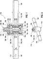
- FIGS. 1 to 3 an embodiment of a device 110 according to the invention for determining a composition of a fuel mixture is shown. This can be used in particular for determining an ethanol content in a fuel.
- the device 110 is in FIG. 1 shown in a sectional view with a sectional plane parallel to a flow direction 112 of the fuel mixture, in FIG. 2 in a perspective view, and in FIG. 3 is a schematic cross section through the device 110 through a measuring area 114 with a sectional plane perpendicular to the cutting plane in FIG. 1 shown, wherein the schematic representation according to FIG. 3 symbolically intended to clarify a field line history.
- the device 110 comprises, as in FIG FIG. 1 can be seen, a housing 116.
- the housing 116 includes a flow tube section 118 with hydraulic connections 120, for example, for connecting a fuel line.
- the hydraulic connections 120 can be configured in a standardized manner, for example.
- the housing 116 in the measuring region 114 in this embodiment by way of example symmetrically surrounded by the hydraulic ports 120, a receptacle 122, for example with a cylindrical receiving bore 124.
- a plug-in cartridge 126 is introduced, substantially perpendicular to the flow direction 112 which represents the actual measuring device in this embodiment.
- This plug-in cartridge 126 comprises a flow-through housing element 128 in the form of a metallic cup 130.
- This cup comprises a cylindrical cup wall 132 and a cup bottom 134.
- An axis 135 of the cup 130 or the Einsteckkartusche 126 which is perpendicular to the cup bottom 134 and parallel to the cup wall
- the cup wall 132 encloses a measuring volume 136 of the measuring area 114.
- the cup wall 132 has, at least opposite and facing away from the flow direction 112, a plurality of bores 138, which in this embodiment are configured as a bore matrix are. Through these holes 138, which act as flow holes, fuel mixture in FIG. 1 on the left side in the measuring volume 136 of the measuring area 114 and on the right side in FIG. 1 emerge from this again or vice versa.
- the plug-in cartridge 126 can be provided, for example, at the top with an additional blind hole bore, which can serve as a receptacle of a temperature sensor.
- the housing element 128 or the cup 130 concentrically surround a pin-shaped inner conductor 140 in the illustrated exemplary embodiment. This is therefore surrounded by fuel mixture in the measurement volume 136.
- the inner conductor 140 is connected at its lower end to the metallic cup bottom 134 by the inner conductor 140 is inserted into this cup bottom 134.
- the inner conductor 140 is embedded in a dielectric 142, for example a plastic, by means of which the inner conductor 140 is electrically separated from a plug housing 144.
- the plug housing 144 is part of a connecting device 146, which in this case is designed in the form of a coaxial plug 148. This includes, in addition to the plug housing 144, a contact 150 of the inner conductor 140.
- the coaxial plug 150 may be designed as an SMA plug.
- the plug housing 144 is bolted at its upper end to a cup rim 152 of the cup 130.
- the plug housing 144 and the cup 130 are therefore preferably electrically connected to each other.
- the plug housing 144 and the cup 130 are thereby electrically connected to each other.
- the cup 130 itself may, for example, be connected to an outer conductor or plug housing of the connecting device 146, for example a coaxial plug.
- the inner conductor preferably forms a short-circuited coaxial line with the cup.
- at least one sealing element 154 may be introduced, for example in the form of one or more O-rings, for example made of a fuel-resistant material.
- one or more sealing elements 154 may also be provided between the insertion cartridge 126 and the wall of the receptacle 122 of the housing 116, for example in corresponding annular grooves of the cup 130, as in FIG FIG. 1 indicated.
- this can for example be secured by a lock fuse 156, for example, also a screw, so that the Einsteckkartusche 126 is firmly anchored in the receptacle 122.
- the flow cross-section from an originally small flow cross-section A 0 in the region of the hydraulic connections 120 to a flow cross section A 1 in the region of the measuring volume 136 continues to expand.
- This expansion takes place in the illustrated embodiment continuously through shells 158, which may be part of the Einsteckkartusche 126 and which may be made for example of a plastic material.
- the in the Figures 1 and 2 illustrated device 110 has a comparatively easy to manufacture and yet effective construction.
- the innermost component of the device 110 embodied as a measuring sensor is the cup 130 which is cylindrical in this case and which can be produced from corrosion-resistant and fuel-compatible metal.
- the inner conductor 140 is preferably added according to the coaxial principle, so that the Einsteckkartusche 126 is in principle a coaxial sensor.
- the inner conductor 140 is conductively connected to the cup bottom 134, wherein the cup itself is flowed through by bores 138 due to the matrix.
- the bores 138 may be dimensioned in total from their flow cross-section forth such that the flow cross-section A 0 is maintained by the total number of holes 138 on one side of the cup 130.
- the cross-section of the fuel-resistant and preferably SAE-standard-conforming connection A 0 is continuously widened to the bore matrix cross section by means of the inserted shells 158.
- the bore diameter of the individual holes 138 are preferably small compared to the minimum wavelength occurring in the fuel mixture. This avoids unwanted radiation into the environment.
- the measuring principle of the device 110 according to the Figures 1 and 2 is an example of the sectional view according to FIG. 3 be explained. This illustration shows, as stated above, a sectional view perpendicular to the cutting plane in FIG. 1 It should be noted that this is only a schematic representation, on the basis of which the course of the electric field lines 160 at a single frequency can be explained.
- the device 110 may be connected via the connecting device 146, for example via a coaxial, standardized connector (eg SMA-RP), with a high frequency (HF) sensor circuit.
- the device 110 can be supplied with microwave signals or generally high-frequency signals of different frequencies, and it can response signals on the same Connecting device 146 are detected.
- the connecting device 146 thus preferably serves at the same time for coupling in microwave signals and for coupling out response signals.
- One or more parameters can be determined in each case from the coupled-in signal and the response signal, as well as the course of these parameters via the frequency of the coupled-in radiation.
- An essential characteristic, as described above, is the permittivity.
- a comparison with reference curves can be made for this purpose, for example by adapting linear coefficients, for example by minimizing error squares or using similar adaptation methods.
- the filled with fuel mixture measuring volume 136 in the form of the filled coaxial line section depending on the loss characteristics of the fuel mixture (described for example by the imaginary part of the permittivity of the fuel mixture) a damping and depending on the real part of the permittivity a retarding effect on leading and returning waves.
- the returning wave experiences at the end of the short-circuited coaxial line in the area of the cup bottom 134 a defined phase jump of, for example, 180 °.
- the parameter is determined at different frequencies over the widest possible frequency range. For example, this can be done by using an ultra-wideband sensor (UWB).
- UWB ultra-wideband sensor
- the permittivity is not only determined for individual frequency lines, but their course over the entire measured frequency range, for example, a frequency range of 1.5 GHz to 8.5 GHz. This considerably increases the information content of the measurement.
Landscapes
- Engineering & Computer Science (AREA)
- Chemical & Material Sciences (AREA)
- Physics & Mathematics (AREA)
- Health & Medical Sciences (AREA)
- Life Sciences & Earth Sciences (AREA)
- General Engineering & Computer Science (AREA)
- Mechanical Engineering (AREA)
- Combustion & Propulsion (AREA)
- Analytical Chemistry (AREA)
- Pathology (AREA)
- Immunology (AREA)
- Biochemistry (AREA)
- General Health & Medical Sciences (AREA)
- General Physics & Mathematics (AREA)
- Oil, Petroleum & Natural Gas (AREA)
- Electromagnetism (AREA)
- Food Science & Technology (AREA)
- Medicinal Chemistry (AREA)
- General Chemical & Material Sciences (AREA)
- Chemical Kinetics & Catalysis (AREA)
- Investigating Or Analyzing Materials By The Use Of Electric Means (AREA)
- Liquid Carbonaceous Fuels (AREA)
Description
- Aus dem Stand der Technik sind Verfahren und Vorrichtungen zur Bestimmung von Zusammensetzungen von Kraftstoffgemischen bekannt. Beispielsweise werden in Kraftfahrzeugen zunehmend Kraftstoffgemische eingesetzt, welche neben den eigentlichen Mineralöl-Kraftstoffen eine Beimischung an Ethanol und/oder anderen Alkoholen verarbeiten können. Üblicherweise werden dabei die Parameter der Motorsteuerung des Kraftfahrzeugs auf die Zusammensetzung des Kraftstoffgemischs angepasst. Zu diesem Zweck werden jedoch in vielen Fällen Kenntnisse über die Zusammensetzung des Kraftstoffgemischs, insbesondere eines Ethanol-Kraftstoff-Mischungsverhältnisses, vorausgesetzt. Ein bekanntes Messverfahren ist dabei die Messung einer Absorption, Transmission oder Reflexion von Mikrowellen durch das Kraftstoffgemisch. Ein Beispiel einer Vorrichtung, welche zu diesem Zweck eingerichtet ist, ist aus
DE 34 12 704 A1 bekannt. Weiterhin ist aus der nachveröffentlichtenDE 10 2008 044 383.2 ein Verfahren zur Bestimmung einer Zusammensetzung eines Kraftstoffgemischs bekannt, bei welchem über einen größeren Frequenzbereich hinweg ein charakteristischer Verlauf einer bestimmten Antwort auf eine Mikrowelleneinstrahlung zur Ermittlung der Eigenschaften des Kraftstoffgemischs erfasst und daraus auf die Zusammensetzung des Kraftstoffgemischs geschlossen wird. Ein Vorteil des inDE 10 2008 044 383.2 beschriebenen Verfahrens besteht insbesondere darin, dass die Genauigkeit durch Verwendung größerer Frequenzbereiche gesteigert werden kann, so dass beispielsweise Alkohol-KraftstoffGemische, welche zusätzlich noch einen Wasseranteil und/oder Additive enthalten, erheblich genauer charakterisiert werden können als mit herkömmlichen Verfahren. Es besteht jedoch ein Verbesserungspotenzial hinsichtlich der Einkopplung und Auskopplung der Mikrowellensignale in den bzw. aus dem Kraftstoff.DE102006034884 offenbart eine Vorrichtung zur Bestimmung der Zusammensetzung eines Fluids, die einen Koaxialleitungsresonator bestehend aus einem löchrigen, becherförmigen Aussenleiter und einem mit dem Aussenleiter am Ende kurzgeschlossenen Innenleiter aufweist. Die vom in das zu untersuchende Fluid eingetauchten Koaxialleiter reflektierten Mikrowellen werden ausgewertet, um die Zusammensetzung zu bestimmen. - Es wird eine Vorrichtung vorgeschlagen, welche zur Bestimmung einer Zusammensetzung eines Kraftstoffgemischs einsetzbar sind. Auf diese Weise können insbesondere dielektrische Eigenschaften von Kraftstoffen zur Bestimmung des Ethanolgehalts von Kraftstoffgemischen herangezogen werden. Alternativ oder zusätzlich können andere Anteile an dem Kraftstoffgemisch quantitativ bestimmt werden, beispielsweise Wasseranteile und/oder Anteile von Additiven.
- Die erfindungsgemässe Vorrichtung ist in Anspruch 1 definiert.
- Das Gehäuseelement ist vorzugsweise aus einem kraftstoffbeständigen Material hergestellt, beispielsweise aus einem kraftstoffbeständigen Metall, wie beispielsweise einem Edelstahl oder einem anderen metallischen Material. Ein bevorzugtes Material ist insbesondere Edelstahl vom Typ 1.4301.
- Unter Mikrowellensignalen sind dabei allgemein elektromagnetische Hochfrequenzsignale zu verstehen, welche vorzugsweise in einem Frequenzbereich von oberhalb von 100 MHz oder sogar 300 MHz liegen, beispielsweise in einem Frequenzbereich zwischen 300 MHz und 300 GHz, insbesondere zwischen 300 MHz und 20 GHz, vorzugsweise zwischen 500 MHz und 10 GHz und besonders bevorzugt im Bereich von 0,5 und 8,5 GHz.
- Die Achse des Bechers erstreckt sich quer zu einer Strömungsrichtung des Kraftstoffgemischs durch die Vorrichtung, d.h. quer zur Strömungsrohrachse. Beispielsweise kann sich die Becherachse im Wesentlichen senkrecht, d.h. beispielsweise unter einem Winkel von 90°±20°, vorzugsweise 90°±10° und besonders bevorzugt 90°±5°, zu einer Strömungsrohrachse erstrecken. Der Becher kann insbesondere (vorzugsweise außerhalb des Strömungsquerschnitts) einen geschlossenen Becherboden aufweisen. Der Becher kann somit als an einem Ende durch den Becherboden geschlossener Hohlzylinder beschrieben werden. Der Becher ist elektrisch leitend mit dem Innenleiter verbunden sein, insbesondere im Bereich des Becherbodens. Beispielsweise kann der Innenleiter in den Becherboden hineinragen, hineingesteckt sein (beispielsweise wenn der Innenleiter als Steckerstift ausgestaltet ist) oder auf andere Weise elektrisch leitend mit dem Becherboden verbunden sein.
- Das Gehäuseelement, insbesondere der Becher, kann insbesondere eine Mehrzahl von Bohrungen aufweisen, durch welche ein Einströmen von Kraftstoff ins Innere des Bechers ermöglicht wird sowie ein Ausströmen von Kraftstoff aus dem Inneren des Bechers. Vorzugsweise weist der Becher also eine Mehrzahl von Bohrungen auf. Die Bohrungen weisen vorzugsweise einen Durchmesser auf, welcher erheblich kleiner ausgestaltet ist als die kleinste Wellenlänge der eingekoppelten Mikrowellen in dem Kraftstoffgemisch. Auf diese Weise kann eine Auskopplung von Mikrowellen, welche sich zwischen dem Innenleiter und dem Becher bzw. der Innenwand des Bechers ausbilden, vermieden werden. Vorzugsweise weisen die Bohrungen einen Durchmesser auf, welcher kleiner ist als 2 mm, insbesondere kleiner als 1 mm. Beispielsweise ist für E100, also Kraftstoff mit einem nominellen Ethanolanteil von 100%, bei einer Frequenz f=19 GHz die minimale Wellenlänge λ=7 mm. Die Bohrungen können dabei grundsätzlich einen beliebigen Querschnitt aufweisen. Besonders bevorzugt sind runde Querschnitte. Auch nicht-runde Querschnitte sind jedoch grundsätzlich denkbar. Unter einem "Durchmesser" bei nicht-runden Querschnitten, beispielsweise polygonalen Querschnitten, ist unter einem "Durchmesser" ein "Äquivalentdurchmesser" zu verstehen, beispielsweise ein Durchmesser eines Kreises mit gleicher Öffnungsfläche.
- Die Verbindungsvorrichtung soll zum Ein- und/oder Auskoppeln von Mikrowellensignalen dienen. Insbesondere kann diese Verbindungsvorrichtung einen Stecker und/oder eine Steckverbindung aufweisen. Besonders bevorzugt sind hierbei genormte Steckverbindungen. Beispielsweise können Koaxialstecker verwendet werden, bei welchen mindestens ein Kontakt zur Beaufschlagung des Innenleiters mit Mikrowellensignalen vorgesehen ist, also zur Einkopplung und/oder Auskopplung von Mikrowellensignalen. Der Kontakt wird bei einem Koaxialstecker von mindestens einem abschirmenden Steckerteil umgeben. Beispielsweise können hierbei SMA-RP-Steckverbinder eingesetzt werden.
- Vorzugsweise sind die Bohrungen des Bechers jeweils der Strömungsrichtung zuweisend ausgerichtet, so dass der Becher der Kartusche ohne Umleitung der Strömung von dem Kraftstoffgemisch durchströmbar ist. Die Aufnahme umfasst eine Erweiterung in dem Gehäuse, mit mindestens einer Aufnahmebohrung, in welche die Kartusche quer zur Strömungsrichtung einsteckbar ist. Die einsteckbare Aufnahme kann dabei reversibel oder auch permanent erfolgen. Nach Einstecken der Kartusche kann beispielsweise eine Fixierung der Kartusche in der Aufnahme erfolgen, beispielsweise durch eine Verschraubung, Verstemmung, Klemmringe oder andere Arten von Fixierungen. Weiterhin kann die Einsteckkartusche insbesondere mittels mindestens eines Dichtelements gegenüber dem Strömungsrohrabschnitt abgedichtet sein. Beispielsweise können zu diesem Zweck ein, zwei, vier oder mehrere O-Ringe vorgesehen sein. Die oben beschriebene Verbindungsvorrichtung kann beispielsweise auf einer Stirnseite der Kartusche außerhalb des Strömungsrohrabschnitts angeordnet sein, so dass beispielsweise der Strömungsrohrabschnitt, die Kartusche und die Verbindungsvorrichtung, beispielsweise die Steckverbindung, eine T-Konfiguration bilden. Weiterhin kann der Strömungsrohrabschnitt beispielsweise zwei oder mehr Anschlüsse aufweisen, beispielsweise einen Zulaufanschluss und einen Ablaufanschluss. Diese Anschlüsse können genormt ausgestaltet sein, beispielsweise in Form von kostengünstigen, hydraulischen genormten Anschlüssen, beispielsweise nach der SAE-Norm.
- Der Strömungsrohrquerschnitt ist in dem Messbereich gegenüber dem Strömungsrohrquerschnitt außerhalb des Messbereichs aufgeweitet. Dies bedeutet, dass der Messbereich in einem größeren Querschnitt durchströmt wird als sonstige Bereiche der Vorrichtung, beispielsweise Bereiche des Strömungsrohrs außerhalb des Messbereichs. In anderen Worten kann die Strömung im Messbereich aufgeweitet sein. Die Aufweitung erfolgt dadurch, dass in dem Messbereich eine, zwei oder mehr Schalen vorgesehen sind, und zwar als Bestandteil der Kartusche, welche für die Aufweitung in dem Messbereich sorgen, und zwar für eine kontinuierliche Aufweitung, also eine Aufweitung mit einem im Wesentlichen linearen Verlauf. Die Aufweitungsschalen können beispielsweise Totvolumina am Übergang zwischen dem Strömungsrohrabschnitt und dem Messbereich, beispielsweise am Übergang zwischen dem Strömungsrohrabschnitt und der Einsteckkartusche, vermeiden. Die Schalen können beispielsweise ringförmig ausgestaltet sein und beispielsweise ebenfalls konzentrisch um den Innenleiter in der Einsteckkartusche aufgenommen sein. Die Schalen können beispielsweise aus einem Kunststoffmaterial, beispielsweise einem kraftstoffbeständigen Kunststoffmaterial, beispielsweise einem fluorierten Polyethylen, hergestellt sein. Bei der Bestimmung einer Zusammensetzung eines Kraftstoffgemischs kommt ein Verfahren zum Einsatz, bei welchem über einen Frequenzbereich hinweg Mikrowellensignale unter Verwendung einer Vorrichtung gemäß einer oder mehreren der oben beschriebenen Ausgestaltungen in das Kraftstoffgemisch eingekoppelt werden. Dabei werden Antwortsignale unter Verwendung der Vorrichtung empfangen. Antwortsignale können dabei beispielsweise reflektierte und/oder transmittierte Signale sein, welche beispielsweise ebenfalls über die Verbindungsvorrichtung ausgekoppelt werden können. Aus einem Vergleich der eingekoppelten Mikrowellensignale und der Antwortsignale wird dabei mindestens eine Kenngröße in Abhängigkeit von der Mikrowellenfrequenz der eingekoppelten Mikrowellensignale bestimmt. Aus einem Verlauf der Kenngröße über die Mikrowellenfrequenz wird dabei auf die Zusammensetzung des Kraftstoffgemischs geschlossen.
- Dabei lässt sich grundsätzlich das in
DE 10 2008 044 383.2 beschriebene Verfahren einsetzen. Auch andere Verfahren sind jedoch grundsätzlich möglich. Das Antwortsignal stellt dabei allgemein eine Reaktion des Kraftstoffgemischs auf die Einstrahlung des eingekoppelten Signals dar. Beispielsweise kann es sich dabei allgemein um transmittierte, reflektierte, remittierte oder emittierte Signale oder um Kombinationen mehrerer Arten dieser Signale handeln. Alternativ oder zusätzlich können auch aus der Absorption, d.h. einem Fehlen von Signalanteilen, Rückschlüsse gezogen werden. Die Kenngröße kann dabei grundsätzlich eine beliebige Größe umfassen, welche aus den eingekoppelten Mikrowellensignalen und den Antwortsignalen gebildet wird. Dabei können beispielsweise auch Linearkombinationen aus Amplituden und/oder Phasen der eingekoppelten Signale und entsprechenden Größen der Antwortsignale gebildet werden. Beispielsweise kann eine Differenz zwischen einer Amplitude der eingekoppelten Mikrowellenstrahlung und einer Amplitude der Antwortmikrowellenstrahlung und eine Differenz aus der Phase der eingekoppelten Mikrowellenstrahlung und der Phase der ausgekoppelten Mikrowellenstrahlung gebildet werden. Die Differenzen können dann jeweils die Kenngröße bilden und/oder einen Teil dieser Kenngröße. Entsprechend der Art des Vergleichs der eingekoppelten Signale und der Antwortsignale kann die Kenngröße beispielsweise mindestens eine der folgenden Kenngrößen umfassen: eine Permitivität, insbesondere komplexe Permitivität; eine Permitivitätszahl, insbesondere eine komplexe Permitivitätszahl; eine Absorption, insbesondere eine komplexe Absorption; eine Transmission, insbesondere eine komplexe Transmission. Unter komplexen Größen ist dabei jeweils eine Größe zu verstehen, welche eine Amplitude und eine Phase beinhaltet. Die Permitivität, welche häufig auch mit dem Buchstaben ε bezeichnet wird, beschreibt die Durchlässigkeit von Materialien für elektrische Felder. Sie ist eine Materialeigenschaft von Dielektrika oder zumindest nur schwach elektrisch leitfähigen Materialien, welche sich bei der Beaufschlagung dieser Materialien mit elektrischen Feldern äußert. Sie stellt die Proportionalitätskonstante zwischen der elektrischen Flussdichte D und dem elektrischen Feld dar. Die Permitivitätszahl, häufig auch als εr bezeichnet oder auch als relative Permitivität, ist das Verhältnis der Permitivität ε zur elektrischen Feldkonstante ε0 (Permitivität des Vakuums). - Bei dem Verfahren werden Mikrowellensignale über einen Frequenzbereich hinweg eingekoppelt. Dies bedeutet, dass Mikrowellensignale mit mindestens zwei Mikrowellenfrequenzen eingekoppelt werden. Diese zwei Mikrowellenfrequenzen können nacheinander und/oder gleichzeitig eingekoppelt werden. Die Mikrowellenfrequenzen decken vorzugsweise einen Frequenzbereich von mindestens 100 MHz ab. Dabei kann dieser Frequenzbereich durch die mindestens zwei Mikrowellenfrequenzen kontinuierlich oder auch in regelmäßigen oder unregelmäßigen Schritten abgedeckt sein. Besonders bevorzugt ist es, wenn die eingekoppelten Mikrowellensignale eine Ultrabreitband-Mikrowellenstrahlung umfassen. Unter einer Ultrabreitband-Mikrowellenstrahlung (englisch Ultra Wide Band, UWB) wird dabei eine Mikrowellenstrahlung im Sinne der obigen Definition verstanden, welche einen extrem großen Frequenzbereich nutzt, mit einer Bandbreite von mindestens 500 MHz. Wie oben dargestellt, wird bei dem vorgeschlagenen Verfahren aus dem Verlauf der Kenngröße über die Mikrowellenfrequenz auf die Zusammensetzung des Kraftstoffgemischs geschlossen. Dieser Verlauf kann beispielsweise in einem einzelnen Schritt bestimmt werden, beispielsweise indem die Kenngrößen über den Frequenzbereich hinweg gleichzeitig und/oder nacheinander bestimmt werden, oder es kann eine iterative oder schrittweise Bestimmung der Kenngrößen über den Frequenzbereich hinweg erfolgen.
- Zur Auswertung des gemessenen Verlaufs der Kenngröße und somit zur Bestimmung der Zusammensetzung des Kraftstoffgemischs können grundsätzlich beliebige analytische, semiempirische oder empirische Verfahren herangezogen werden. Allgemein kann unter der Bestimmung der Zusammensetzung des Kraftstoffgemischs beispielsweise die Bestimmung einer Konzentration einer einzelnen oder mehrerer Komponenten dieses Kraftstoffgemischs und/oder ein Mischungsverhältnis verstanden werden. Dementsprechend kann die Bestimmung der Zusammensetzung des Kraftstoffgemischs vollständig, im Sinne einer vollständigen Analyse, oder lediglich teilweise erfolgen, beispielsweise indem lediglich die Konzentration und/oder das Mischungsverhältnis einer einzelnen Komponente und/oder mehrerer Komponenten bestimmt werden. Beispielsweise können Referenzverläufe der Kenngrößen analytisch, empirisch oder semiempirisch bestimmt werden. So kann das Kraftstoffgemisch beispielsweise mindestens zwei, vorzugsweise drei, vier oder mehr Komponenten umfassen, wobei jeweils Referenzverläufe der Kenngröße über die Frequenz der eingekoppelten Mikrowellensignale für diese Komponenten zumindest teilweise bekannt sind. Beispielsweise können diese Referenzverläufe dadurch ermittelt werden, dass die jeweiligen Komponenten als Reinstoffe oder als im Wesentlichen reine Stoffe mittels des oben beschriebenen Verfahrens untersucht und dabei Kennlinienverläufe aufgenommen werden. Diese Kennlinienverläufe der einzelnen Komponenten können dann als Referenzverläufe für die jeweilige Komponente beispielsweise in einem Speicher hinterlegt sein. Bei der eigentlichen Messung der Zusammensetzung des Kraftstoffgemischs kann dann aus dem gemessenen Verlauf der tatsächlichen Kenngröße mittels der bekannten Referenzverläufe auf die Zusammensetzung des Kraftstoffgemischs geschlossen werden. Dieser Rückschluss auf die Zusammensetzung kann beispielsweise durch einen Einzelvergleich des gemessenen Verlaufs mit den Referenzverläufen und/oder einer Interpolation oder Extrapolation derselben erfolgen. Auch andere Verfahren sind denkbar. So kann beispielsweise eine Linearkombination der Referenzverläufe gebildet werden, um auf diese Weise die Linearkombination der Referenzverläufe an den gemessenen Verlauf anzupassen. Aus den bei dieser Anpassung an den gemessenen Verlauf bestimmten Koeffizienten der Linearkombination, welche beispielsweise nach bekannten Anpassungsverfahren bestimmt werden können, kann dann auf die Anteile der einzelnen Komponenten geschlossen werden. Auch andere Möglichkeiten sind jedoch denkbar, beispielsweise indem eine Vielzahl von Kombinationen und entsprechende Referenzverläufe für verschiedene Kraftstoffgemischzusammensetzungen in einem Speicher hinterlegt werden und dementsprechend aus dem gemessenen Verlauf der Kenngröße Referenzverläufe mit der größtmöglichen Übereinstimmung herausgesucht werden. Auch auf diese Weise lässt sich auf die Zusammensetzung des Kraftstoffgemischs schließen. Zusätzlich kann die Temperatur nahe dem Kraftstoffvolumen gemessen werden um die TemperaturAbhängigkeit der Messgrößen zu kompensieren.
- Die oben beschriebene Vorrichtung weist gegenüber bekannten Vorrichtungen zahlreiche Vorteile auf. So lässt sich ein von dem Kraftstoffgemisch durchströmter Messfühler realisieren, der aus mehreren Einzelteilen zusammengesetzt sein kann, wobei eine einfache und kostengünstige Herstellung möglich ist, insbesondere unter Verwendung der oben beschriebenen Einsteckkartusche. Weiterhin lässt sich ein Messfühler mit einem reduzierten Volumen ohne Totvolumen realisieren. Der Messfühler kann elektromagnetisch neutral ausgestaltet werden, ohne die Umgebung des Messfühlers mit Mikrowellenstrahlung zu beaufschlagen. Der Messfühler lässt sich kostengünstig ausgestalten und beispielsweise mit SAE-Norm-konformen hydraulischen Anschlüssen versehen.
- Ausführungsbeispiele der Erfindung sind in den Figuren dargestellt und werden in der nachfolgenden Beschreibung näher erläutert.
- Es zeigen:
- Figur 1
- einen Querschnitt durch eine erfindungsgemäße Vorrichtung zur Bestimmung einer Zusammensetzung eines Kraftstoffgemischs mit einer Schnittebene parallel zu einer Strömungsrichtung;
- Figur 2
- eine perspektivische Darstellung der Vorrichtung gemäß
Figur 1 ; und - Figur 3
- einen Querschnitt durch einen Messbereich der Vorrichtung gemäß
Figur 1 mit einer Schnittebene senkrecht zur Schnittebene gemäßFigur 1 . - In den
Figuren 1 bis 3 ist ein Ausführungsbeispiel einer erfindungsgemäßen Vorrichtung 110 zu Bestimmung einer Zusammensetzung eines Kraftstoffgemischs dargestellt. Diese kann insbesondere zur Bestimmung eines Ethanolanteils in einem Kraftstoff eingesetzt werden. Die Vorrichtung 110 ist inFigur 1 in einer Schnittdarstellung mit einer Schnittebene parallel zu einer Strömungsrichtung 112 des Kraftstoffgemischs dargestellt, inFigur 2 in einer perspektivischen Darstellung, und inFigur 3 ist ein schematischer Querschnitt durch die Vorrichtung 110 durch einen Messbereich 114 mit einer Schnittebene senkrecht zur Schnittebene inFigur 1 gezeigt, wobei die schematische Darstellung gemäßFigur 3 symbolisch einer Verdeutlichung eines Feldlinienverlaufs dienen soll. - Die Vorrichtung 110 umfasst, wie in
Figur 1 erkennbar ist, ein Gehäuse 116. Das Gehäuse 116 umfasst einen Strömungsrohrabschnitt 118 mit hydraulischen Anschlüssen 120, beispielsweise zum Anschließen einer Kraftstoffleitung. Die hydraulischen Anschlüsse 120 können beispielsweise genormt ausgestaltet sein. Weiterhin umfasst das Gehäuse 116 in dem Messbereich 114, in diesem Ausführungsbeispiel exemplarisch symmetrisch von den hydraulischen Anschlüssen 120 umgeben, eine Aufnahme 122, beispielsweise mit einer zylindrischen Aufnahmebohrung 124. In dieser Aufnahmebohrung 124 ist, im Wesentlichen senkrecht zur Strömungsrichtung 112, eine Einsteckkartusche 126 eingebracht, welche in diesem Ausführungsbeispiel die eigentliche Messvorrichtung darstellt. Diese Einsteckkartusche 126 umfasst ein durchströmbares Gehäuseelement 128 in Form eines metallischen Bechers 130. Dieser Becher umfasst eine zylindrische Becherwand 132 und einen Becherboden 134. Eine Achse 135 des Bechers 130 bzw. der Einsteckkartusche 126, welche sich senkrecht zum Becherboden 134 und parallel zu der Becherwand 132 erstreckt, steht im Wesentlichen senkrecht auf die Strömungsrichtung 112. Die Becherwand 132 umschließt ein Messvolumen 136 des Messbereichs 114. Die Becherwand 132 weist, zumindest entgegen und abgewandt der Strömungsrichtung 112, eine Mehrzahl von Bohrungen 138 auf, welche in diesem Ausführungsbeispiel als Bohrungsmatrix ausgestaltet sind. Durch diese Bohrungen 138, welche als Strömungsbohrungen fungieren, kann Kraftstoffgemisch inFigur 1 auf der linken Seite in das Messvolumen 136 des Messbereichs 114 eintreten und auf der rechten Seite inFigur 1 aus diesem wieder austreten oder umgekehrt. Die Einsteckkartusche 126 kann zum Beispiel an der Oberseite mit einer zusätzlichen Sacklochbohrung versehen werden, die als Aufnahme eines Temperatursensors dienen kann. - Das Gehäuseelement 128 bzw. der Becher 130 umschließen in dem dargestellten Ausführungsbeispiel konzentrisch einen stiftförmigen Innenleiter 140. Dieser wird also in dem Messvolumen 136 von Kraftstoffgemisch umspült. Der Innenleiter 140 ist an seinem unteren Ende mit dem metallischen Becherboden 134 verbunden, indem der Innenleiter 140 in diesen Becherboden 134 eingesteckt ist. Oberhalb des Messvolumens 136 ist der Innenleiter 140 in einem Dielektrikum 142 eingebettet, beispielsweise einem Kunststoff, durch welchen der Innenleiter 140 elektrisch gegenüber einem Steckergehäuse 144 getrennt ist. Das Steckergehäuse 144 ist Teil einer Verbindungsvorrichtung 146, welche in diesem Fall in Form eines Koaxialsteckers 148 ausgestaltet ist. Diese umfasst neben dem Steckergehäuse 144 einen Kontakt 150 des Innenleiters 140. Beispielsweise kann der Koaxialstecker 150 als SMA-Stecker ausgestaltet sein.
- Das Steckergehäuse 144 ist an seinem oberen Ende mit einem Becherrand 152 des Bechers 130 verschraubt. Das Steckergehäuse 144 und der Becher 130 sind also vorzugsweise elektrisch miteinander verbunden. Das Steckergehäuse 144 und der Becher 130 sind dadurch elektrisch miteinander verbunden. Der Becher 130 selbst kann beispielsweise mit einem Außenleiter oder Steckergehäuse der Verbindungsvorrichtung 146, beispielsweise eines Koaxialsteckers, verbunden sein. Auf diese Weise bildet der Innenleiter mit dem Becher vorzugsweise eine kurzgeschlossene Koaxialleitung. Zwischen dem eingeschraubten Steckergehäuse 144 und dem Becher 130 kann zusätzlich, wie in
Figur 1 dargestellt, mindestens ein Dichtelement 154 eingebracht sein, beispielsweise in Form eines oder mehrerer O-Ringe, beispielsweise aus einem kraftstoffbeständigen Material. Weiterhin können auch zwischen der Einsteckkartusche 126 und der Wand der Aufnahme 122 des Gehäuses 116 ein oder mehrere Dichtelemente 154 vorgesehen sein, beispielsweise in entsprechenden Ringnuten des Bechers 130, wie inFigur 1 angedeutet. An der der Verbindungsvorrichtung 146 gegenüberliegenden Stirnseite der Einsteckkartusche 126 kann diese beispielsweise durch eine Verschlusssicherung 156 gesichert sein, beispielsweise ebenfalls eine Verschraubung, so dass die Einsteckkartusche 126 fest in der Aufnahme 122 verankert ist. - Im Bereich der Einsteckkartusche 126 findet weiterhin eine Aufweitung des Strömungsquerschnitts von einem ursprünglich kleinen Strömungsquerschnitt A0 im Bereich der hydraulischen Anschlüsse 120 hin zu einem Strömungsquerschnitt A1 im Bereich des Messvolumens 136 statt. Diese Aufweitung erfolgt in dem dargestellten Ausführungsbeispiel kontinuierlich durch Schalen 158, welche Bestandteil der Einsteckkartusche 126 sein können und welche beispielsweise aus einem Kunststoffmaterial hergestellt sein können.
- Die in den
Figuren 1 und 2 dargestellte Vorrichtung 110 weist einen vergleichsweise einfach herzustellenden und dennoch effektiven Aufbau auf. Innerstes Bauteil der als Messfühler ausgestalteten Vorrichtung 110 ist der in diesem Fall zylindrisch ausgestaltete Becher 130, welcher aus korrosionsbeständigem und kraftstoffverträglichem Metall hergestellt sein kann. In diesem ist vorzugsweise nach dem koaxialen Prinzip der Innenleiter 140 aufgenommen, so dass die Einsteckkartusche 126 prinzipiell ein koaxialer Messfühler ist. Der Innenleiter 140 ist leitend mit dem Becherboden 134 verbunden, wobei der Becher selbst aufgrund der Matrix an Bohrungen 138 durchströmbar ist. Die Bohrungen 138 können insgesamt von ihrem Durchflussquerschnitt her derart bemessen sein, dass der Durchflussquerschnitt A0 durch die Gesamtzahl der Bohrungen 138 auf einer Seite des Bechers 130 erhalten bleibt. Zur Aufweitung der Strömung wird der Querschnitt des kraftstoffbeständigen und vorzugsweise SAE-Norm-konformen Anschlusses A0 kontinuierlich auf den Bohrungsmatrixquerschnitt mittels der eingelegten Schalen 158 aufgeweitet. Die Bohrungsdurchmesser der einzelnen Bohrungen 138 sind dabei vorzugsweise klein gegenüber der minimalen, im Kraftstoffgemisch auftretenden Wellenlänge. Damit wird eine unerwünschte Abstrahlung in die Umgebung vermieden. Das Messprinzip der Vorrichtung 110 gemäß denFiguren 1 und 2 soll exemplarisch an der Schnittdarstellung gemäßFigur 3 erläutert werden. Diese Darstellung zeigt, wie oben ausgeführt, eine Schnittdarstellung senkrecht zur Schnittebene inFigur 1 , durch die Achse 135. Es sei darauf hingewiesen, dass es sich hierbei lediglich um eine schematische Darstellung handelt, aufgrund welcher der Verlauf der elektrischen Feldlinien 160 bei einer einzelnen Frequenz erläutert werden kann. - Die Vorrichtung 110 kann über die Verbindungsvorrichtung 146, beispielsweise über einen koaxialen, genormten Steckverbinder (z.B. SMA-RP), mit einer Hochfrequenz (HF)-Sensorschaltung verbunden sein. Über diese kann die Vorrichtung 110 mit Mikrowellensignalen oder allgemein Hochfrequenzsignalen verschiedener Frequenzen beaufschlagt werden, und es können Antwortsignale über dieselbe Verbindungsvorrichtung 146 erfasst werden. Die Verbindungsvorrichtung 146 dient also vorzugsweise gleichzeitig zum Einkoppeln von Mikrowellensignalen und zum Auskoppeln von Antwortsignalen. Jeweils aus eingekoppeltem Signal und Antwortsignal können eine oder mehrere Kenngrößen ermittelt werden, sowie der Verlauf dieser Kenngrößen über die Frequenz der eingekoppelten Strahlung. Eine wesentliche Kenngröße ist, wie oben beschrieben, die Permitivität. Beispielsweise kann aus einer Differenz (Amplitude und Phase) zwischen ausgesendetem bzw. eingekoppeltem und empfangenem Signal bzw. Antwortsignal auf die Permitivität des sich im Messvolumen befindlichen Kraftstoffgemischs geschlossen werden. Der Verlauf der Permitivität und/oder einer oder mehrerer alternativer Kenngrößen über die Frequenz wird zur Identifizierung und Quantifizierung von Einzelkomponenten des Kraftstoffgemischs herangezogen. Wie oben dargestellt kann hierzu beispielsweise ein Vergleich mit Referenzkurven erfolgen, beispielsweise durch eine Anpassung von Linearkoeffizienten, beispielsweise unter Minimierung von Fehlerquadraten oder unter Verwendung ähnlicher Anpassungsverfahren.
- Das mit Kraftstoffgemisch gefüllte Messvolumen 136 in Form des gefüllten Koaxialleitungsabschnitts hat, abhängig von den Verlusteigenschaften des Kraftstoffgemischs (beschrieben beispielsweise durch den Imaginärteil der Permitivität des Kraftstoffgemischs) eine dämpfende und abhängig von dem Realteil der Permitivität eine verzögernde Wirkung auf vorlaufende und rücklaufende Wellen. Die rücklaufende Welle erfährt am Ende der kurzgeschlossenen Koaxialleitung im Bereich des Becherbodens 134 einen definierten Phasensprung von beispielsweise 180°.
- Die Kenngröße wird bei verschiedenen Frequenzen über einen möglichst großen Frequenzbereich hinweg ermittelt. Beispielsweise kann dies durch den Einsatz eines Ultra-Breitband-Sensors (UWB) erfolgen. Durch den Einsatz eines UWBs wird die Permitivität nicht nur bei einzelnen Frequenzlinien ermittelt, sondern deren Verlauf über den gesamten gemessenen Frequenzbereich, beispielsweise einen Frequenzbereich von 1,5 GHz bis 8,5 GHz. Hierdurch wird der Informationsgehalt der Messung erheblich erhöht. Insgesamt lässt sich auf diese Weise eine einfach herzustellende, kostengünstige und einfach zu handhabende sowie zuverlässig abdichtende Messvorrichtung schaffen, welche beispielsweise in Kraftfahrzeugen eingesetzt werden kann, insbesondere in Ottomotoren, jedoch auch in Dieselmotoren.
Claims (5)
- Vorrichtung (110) zur Bestimmung einer Zusammensetzung eines Kraftstoffgemischs, insbesondere zur Bestimmung eines Ethanolanteils und/oder eines Wasseranteils in dem Kraftstoffgemisch, umfassend mindestens ein Gehäuse (116) mit mindestens einem elektrisch leitfähigen, von dem Kraftstoffgemisch durchströmbaren Gehäuseelement (128), wobei in das Gehäuseelement (128) mindestens ein Innenleiter (140) eingebracht ist, wobei der Innenleiter (140) von dem Gehäuseelement (128) zumindest teilweise umschlossen ist, wobei die Vorrichtung (110) weiterhin mindestens eine Verbindungsvorrichtung (146) zum Koppeln von Mikrowellensignalen aufweist, wobei das Gehäuseelement (128) mindestens einen den Innenleiter (140) zumindest teilweise umschließenden und elektrisch leitend mit dem Innenleiter (140) verbunden Becher (130) aufweist,
dadurch gekennzeichnet, dass die Vorrichtung (110) weiterhin mindestens einen von dem Kraftstoffgemisch in einer Strömungsrichtung (112) durchströmbaren Strömungsrohrabschnitt (118) umfasst, wobei das Gehäuse (116) den Strömungsrohrabschnitt umfasst, wobei der Innenleiter (140) und das Gehäuseelement (128) quer, vorzugsweise im Wesentlichen senkrecht, zu der Strömungsrichtung (112) in den Strömungsrohrabschnitt (118) eingebracht sind, und dass die Vorrichtung (110) weiterhin eine Einsteckkartusche (126) umfasst, wobei die Einsteckkartusche (126) den Innenleiter (140) und das Gehäuseelement (128) umfasst und in einem Messbereich (114) quer zur Strömungsrichtung (112) in eine Aufnahme (122) des Strömungsrohrabschnitts (118) eingesteckt ist, wobei das Gehäuseelement (128) und der Innenleiter (140) in einem Messbereich (114) aufgenommen sind, wobei ein Strömungsrohrquerschnitt in dem Messbereich (114) gegenüber einem Strömungsrohrquerschnitt außerhalb des Messbereichs (114) aufgeweitet ist und wobei die Aufweitung kontinuierlich durch Schalen (158) erfolgt, welche Bestandteil der Einsteckkartusche (126) sind. - Vorrichtung (110) nach dem vorhergehenden Anspruch, wobei das Gehäuseelement (128) den Innenleiter (140) koaxial umschließt.
- Vorrichtung (110) nach Anspruch 1 oder 2, wobei der Becher (130) eine Mehrzahl von Bohrungen (138) aufweist, wobei die Bohrungen (138) einen Durchmesser aufweisen, welcher kleiner ist als die kleinste Wellenlänge der eingekoppelten Mikrowellen, insbesondere kleiner als 2 mm, vorzugsweise kleiner als 1 mm.
- Vorrichtung (110) nach einem der vorhergehenden Ansprüche, wobei die Verbindungsvorrichtung (146) mindestens einen Koaxialstecker (148) aufweist, wobei der Koaxialstecker (148) mindestens einen Kontakt (150) zur Beaufschlagung des Innenleiters (140) mit Mikrowellensignalen umfasst.
- Vorrichtung (110) nach Anspruch 1, wobei die Einsteckkartusche (126) mittels mindestens eines Dichtelements (154) gegenüber dem Strömungsrohrabschnitt (118) abgedichtet ist.
Applications Claiming Priority (2)
| Application Number | Priority Date | Filing Date | Title |
|---|---|---|---|
| DE102010029007A DE102010029007A1 (de) | 2010-05-17 | 2010-05-17 | Vorrichtung zur Bestimmung einer Zusammensetzung eines Kraftstoffgemischs |
| PCT/EP2011/054318 WO2011144377A1 (de) | 2010-05-17 | 2011-03-22 | Vorrichtung zur bestimmung einer zusammensetzung eines kraftstoffgemischs mittels eines vom krafstoffgemisch durchströmten koaxialen wellenleiters |
Publications (2)
| Publication Number | Publication Date |
|---|---|
| EP2572094A1 EP2572094A1 (de) | 2013-03-27 |
| EP2572094B1 true EP2572094B1 (de) | 2018-08-08 |
Family
ID=44041637
Family Applications (1)
| Application Number | Title | Priority Date | Filing Date |
|---|---|---|---|
| EP11709417.7A Not-in-force EP2572094B1 (de) | 2010-05-17 | 2011-03-22 | Vorrichtung zur bestimmung einer zusammensetzung eines kraftstoffgemischs mittels eines vom krafstoffgemisch durchströmten koaxialen wellenleiters |
Country Status (6)
| Country | Link |
|---|---|
| US (1) | US9261466B2 (de) |
| EP (1) | EP2572094B1 (de) |
| CN (1) | CN103003553B (de) |
| BR (1) | BR112012029314A2 (de) |
| DE (1) | DE102010029007A1 (de) |
| WO (1) | WO2011144377A1 (de) |
Families Citing this family (10)
| Publication number | Priority date | Publication date | Assignee | Title |
|---|---|---|---|---|
| DE102011085490A1 (de) | 2011-10-31 | 2013-05-02 | Robert Bosch Gmbh | Vorrichtung zur Bestimmung einer Zusammensetzung einer Flüssigkeit |
| US20130119977A1 (en) * | 2011-11-11 | 2013-05-16 | Boris Leonid Sheikman | Sensing element for sensor assembly |
| DE102013205452A1 (de) | 2012-12-27 | 2014-07-03 | Robert Bosch Gmbh | Anordnung zur Bestimmung eines Verdampfungsverhaltens eines Kraftstoffs |
| KR101590573B1 (ko) * | 2013-07-31 | 2016-02-01 | 주식회사 엘지화학 | 순물질 조합을 이용한 혼합물의 특성 평가 방법 및 이를 이용한 시스템 |
| CN103728320B (zh) * | 2013-12-23 | 2015-12-02 | 宁波威瑞泰默赛多相流仪器设备有限公司 | 一种微波流体介质探测器 |
| DE102015220849A1 (de) | 2015-10-26 | 2017-04-27 | Robert Bosch Gmbh | Vorrichtung zur Bestimmung eines Anteils eines in einer Flüssigkeit ungelösten Gases |
| DK3249201T3 (da) * | 2016-05-24 | 2020-08-03 | CleanTech Swiss AG | Indretning til drift af en motor |
| US11016075B2 (en) * | 2017-07-20 | 2021-05-25 | Saudi Arabian Oil Company | Methods and systems for characterization of geochemical properties of hydrocarbons using microwaves |
| WO2023210553A1 (ja) * | 2022-04-27 | 2023-11-02 | 株式会社サンエー | 組成特定プログラム、組成特定装置及び組成特定システム |
| DE102023101256A1 (de) * | 2023-01-19 | 2024-07-25 | Technische Universität Hamburg, Körperschaft des öffentlichen Rechts | Verfahren zur Messung der Qualität eines Kraftstoffes und Messvorrichtung dafür |
Family Cites Families (24)
| Publication number | Priority date | Publication date | Assignee | Title |
|---|---|---|---|---|
| FR2057904A5 (de) | 1969-08-07 | 1971-05-21 | Bendix Corp | |
| IT961071B (it) | 1971-09-04 | 1973-12-10 | Cnen | Sonda ed installazione per la misura di livelli di interfacce di fluidi e delle costanti dielettri che degli stessi |
| SU759927A1 (ru) | 1977-07-13 | 1980-08-30 | Aleksandr A Gromov | Радиоволновый концентратомер 1 . ' |
| US4345202A (en) | 1980-12-19 | 1982-08-17 | General Motors Corporation | Method of detecting soot in engine oil using microwaves |
| US4503384A (en) | 1982-04-28 | 1985-03-05 | General Motors Corporation | Microwave probe for measurement of dielectric constants |
| DE3412704A1 (de) | 1983-04-06 | 1984-10-11 | Nippondenso Co., Ltd., Kariya, Aichi | Vorrichtung zum messen des alkoholgehaltes in kraftstoffgemischen |
| US4580441A (en) * | 1983-05-10 | 1986-04-08 | Nippondenso Co., Ltd. | Diesel smoke meter |
| US4862060A (en) * | 1986-11-18 | 1989-08-29 | Atlantic Richfield Company | Microwave apparatus for measuring fluid mixtures |
| US5361035A (en) * | 1992-02-11 | 1994-11-01 | Ford Motor Company | Resonant cavity flexible fuel sensor and system |
| US5926024A (en) * | 1995-01-04 | 1999-07-20 | Atlantic Richfield Company | System and method for measuring fluid properties by forming a coaxial transmission line in a cased well |
| AU6756198A (en) * | 1996-10-07 | 1998-06-22 | Berwind Corporation | Material interface level sensing |
| US6927583B2 (en) | 2001-05-17 | 2005-08-09 | Siemens Vdo Automotive Inc. | Fuel sensor |
| DE10239409B4 (de) * | 2002-08-28 | 2004-09-09 | Robert Bosch Gmbh | Vorrichtung zum Zünden eines Luft-Kraftstoff-Gemischs in einem Verbrennungsmotor |
| BRPI0204519B1 (pt) | 2002-10-10 | 2016-11-29 | Conselho Nacional Cnpq | equipamento eletrônico para monitoramento da concentração dos componentes em combustíveis líquidos |
| US6989676B2 (en) * | 2003-01-13 | 2006-01-24 | Delphi Technologies, Inc. | Apparatus and method for sensing particle and water concentrations in a medium |
| US20040234916A1 (en) * | 2003-05-21 | 2004-11-25 | Alexza Molecular Delivery Corporation | Optically ignited or electrically ignited self-contained heating unit and drug-supply unit employing same |
| CN1255688C (zh) * | 2003-06-13 | 2006-05-10 | 四川大学 | 一种液体介电常数测量探头 |
| FR2862758B1 (fr) * | 2003-11-20 | 2006-01-13 | Commissariat Energie Atomique | Capteur et ensemble de mesures hydrometriques |
| US7135870B2 (en) | 2004-05-04 | 2006-11-14 | Kam Controls Incorporated | Device for determining the composition of a fluid mixture |
| US7402777B2 (en) * | 2004-05-20 | 2008-07-22 | Alexza Pharmaceuticals, Inc. | Stable initiator compositions and igniters |
| DE102006034884A1 (de) | 2005-07-27 | 2007-04-05 | Ademics Gbr | Messgerät zur Bestimmung der elektromagnetischen Eigenschaften eines Fluids |
| NL2000362C2 (nl) * | 2006-12-07 | 2008-06-10 | Ihc Syst Bv | Systeem en werkwijze voor meten van een concentratieparameter van een vaste stof/vloeistof mengsel in een transportleiding. |
| JP5261631B2 (ja) * | 2007-07-12 | 2013-08-14 | イマジニアリング株式会社 | 点火またはプラズマ発生装置 |
| DE102008044383A1 (de) | 2008-12-05 | 2010-06-10 | Robert Bosch Gmbh | Verfahren zur Bestimmung einer Zusammensetzung eines Kraftstoffgemischs |
-
2010
- 2010-05-17 DE DE102010029007A patent/DE102010029007A1/de not_active Ceased
-
2011
- 2011-03-22 CN CN201180034581.5A patent/CN103003553B/zh not_active Expired - Fee Related
- 2011-03-22 WO PCT/EP2011/054318 patent/WO2011144377A1/de not_active Ceased
- 2011-03-22 EP EP11709417.7A patent/EP2572094B1/de not_active Not-in-force
- 2011-03-22 BR BR112012029314A patent/BR112012029314A2/pt not_active Application Discontinuation
- 2011-03-22 US US13/698,613 patent/US9261466B2/en not_active Expired - Fee Related
Non-Patent Citations (1)
| Title |
|---|
| None * |
Also Published As
| Publication number | Publication date |
|---|---|
| CN103003553A (zh) | 2013-03-27 |
| US20130111980A1 (en) | 2013-05-09 |
| EP2572094A1 (de) | 2013-03-27 |
| US9261466B2 (en) | 2016-02-16 |
| CN103003553B (zh) | 2016-04-13 |
| WO2011144377A1 (de) | 2011-11-24 |
| DE102010029007A1 (de) | 2011-11-17 |
| BR112012029314A2 (pt) | 2016-07-26 |
Similar Documents
| Publication | Publication Date | Title |
|---|---|---|
| EP2572094B1 (de) | Vorrichtung zur bestimmung einer zusammensetzung eines kraftstoffgemischs mittels eines vom krafstoffgemisch durchströmten koaxialen wellenleiters | |
| DE102016120665B3 (de) | Radarsensoreinheit zum Einsatz in rauen Umgebungen | |
| DE102010063167A1 (de) | Mit Mikrowellen arbeitendes Messgerät | |
| DE102008044383A1 (de) | Verfahren zur Bestimmung einer Zusammensetzung eines Kraftstoffgemischs | |
| EP0379644A1 (de) | Verfahren zur Feststellung des Alkoholgehaltes und/oder des Heizwertes von Kraftstoffen | |
| EP2212688B1 (de) | Verfahren zur bestimmung eines kraftstoffanteils in einem motoröl eines kraftfahrzeugs | |
| DE102010045780A1 (de) | Kalibriereinheit für ein Messgerät | |
| EP2796840B1 (de) | Modenkonverter für Füllstandsradar | |
| WO2018082726A1 (de) | Mikrowellenmessanordnung zur bestimmung der beladung einer zweiphasenströmung | |
| DE102009008156A1 (de) | Elektrische Prüfstiftvorrichtung | |
| EP4586396A1 (de) | Radarsensor und hohlleiter-trennstelle | |
| EP1339978B1 (de) | Vorrichtung und verfahren zum messen der einspritzmenge von einspritzdüsen, insbesonderer für kraftfahrzeuge | |
| DE102015220849A1 (de) | Vorrichtung zur Bestimmung eines Anteils eines in einer Flüssigkeit ungelösten Gases | |
| DE602005000472T2 (de) | Testsonde mit integriertem Schaltkreis | |
| EP3813188A1 (de) | Hohlleiteranordnung und antenne | |
| DE102010026020A1 (de) | Messeinrichtung mit einer Messstrecke und einer Referenzstrecke | |
| DE112004000368T5 (de) | Verfahren und Vorrichtung für ein Radarfüllstandsmesssystem | |
| EP3732473B1 (de) | Verfahren zum bestimmen einer qualitätseigenschaft einer betriebsflüssigkeit in einem betriebsflüssigkeitsbehälter für ein kraftfahrzeug und betriebsflüssigkeitsbehälter zum durchführen des verfahrens | |
| DE102015006739A1 (de) | Hochfrequenzleitersystem mit leitungsgebundener HF-Durchführung | |
| EP3150864A1 (de) | Vorrichtung und verfahren zur positionsbestimmung eines zylinderkolbens | |
| EP3642917B1 (de) | Zündkerze mit mehrstufigem isolatorsitz | |
| DE102005020809B3 (de) | Sensor | |
| DE102016008903A1 (de) | Kuppler zwischen einem koaxialen Verbinder und einem Koaxialkabel | |
| DE102016000093A1 (de) | Verfahren zum Abstimmen von Hochfrequenzfiltern und ein derartig abgestimmtes Hochfrequenzfilter | |
| WO2011138385A1 (de) | Nahfeldsensor zur lokalen messung von dielektrischen eigenschaften |
Legal Events
| Date | Code | Title | Description |
|---|---|---|---|
| PUAI | Public reference made under article 153(3) epc to a published international application that has entered the european phase |
Free format text: ORIGINAL CODE: 0009012 |
|
| 17P | Request for examination filed |
Effective date: 20121217 |
|
| AK | Designated contracting states |
Kind code of ref document: A1 Designated state(s): AL AT BE BG CH CY CZ DE DK EE ES FI FR GB GR HR HU IE IS IT LI LT LU LV MC MK MT NL NO PL PT RO RS SE SI SK SM TR |
|
| DAX | Request for extension of the european patent (deleted) | ||
| STAA | Information on the status of an ep patent application or granted ep patent |
Free format text: STATUS: EXAMINATION IS IN PROGRESS |
|
| 17Q | First examination report despatched |
Effective date: 20161107 |
|
| REG | Reference to a national code |
Ref country code: DE Ref legal event code: R079 Ref document number: 502011014563 Country of ref document: DE Free format text: PREVIOUS MAIN CLASS: F02D0019080000 Ipc: F02M0025022000 |
|
| GRAP | Despatch of communication of intention to grant a patent |
Free format text: ORIGINAL CODE: EPIDOSNIGR1 |
|
| RIC1 | Information provided on ipc code assigned before grant |
Ipc: F02D 19/08 20060101ALI20180410BHEP Ipc: F02M 25/022 20060101AFI20180410BHEP Ipc: G01N 22/00 20060101ALI20180410BHEP Ipc: G01N 33/28 20060101ALI20180410BHEP |
|
| STAA | Information on the status of an ep patent application or granted ep patent |
Free format text: STATUS: GRANT OF PATENT IS INTENDED |
|
| INTG | Intention to grant announced |
Effective date: 20180517 |
|
| GRAS | Grant fee paid |
Free format text: ORIGINAL CODE: EPIDOSNIGR3 |
|
| GRAA | (expected) grant |
Free format text: ORIGINAL CODE: 0009210 |
|
| STAA | Information on the status of an ep patent application or granted ep patent |
Free format text: STATUS: THE PATENT HAS BEEN GRANTED |
|
| AK | Designated contracting states |
Kind code of ref document: B1 Designated state(s): AL AT BE BG CH CY CZ DE DK EE ES FI FR GB GR HR HU IE IS IT LI LT LU LV MC MK MT NL NO PL PT RO RS SE SI SK SM TR |
|
| REG | Reference to a national code |
Ref country code: GB Ref legal event code: FG4D Free format text: NOT ENGLISH |
|
| REG | Reference to a national code |
Ref country code: CH Ref legal event code: EP Ref country code: AT Ref legal event code: REF Ref document number: 1027300 Country of ref document: AT Kind code of ref document: T Effective date: 20180815 |
|
| REG | Reference to a national code |
Ref country code: IE Ref legal event code: FG4D Free format text: LANGUAGE OF EP DOCUMENT: GERMAN |
|
| REG | Reference to a national code |
Ref country code: DE Ref legal event code: R096 Ref document number: 502011014563 Country of ref document: DE |
|
| REG | Reference to a national code |
Ref country code: NL Ref legal event code: MP Effective date: 20180808 |
|
| REG | Reference to a national code |
Ref country code: LT Ref legal event code: MG4D |
|
| PG25 | Lapsed in a contracting state [announced via postgrant information from national office to epo] |
Ref country code: NO Free format text: LAPSE BECAUSE OF FAILURE TO SUBMIT A TRANSLATION OF THE DESCRIPTION OR TO PAY THE FEE WITHIN THE PRESCRIBED TIME-LIMIT Effective date: 20181108 Ref country code: GR Free format text: LAPSE BECAUSE OF FAILURE TO SUBMIT A TRANSLATION OF THE DESCRIPTION OR TO PAY THE FEE WITHIN THE PRESCRIBED TIME-LIMIT Effective date: 20181109 Ref country code: SE Free format text: LAPSE BECAUSE OF FAILURE TO SUBMIT A TRANSLATION OF THE DESCRIPTION OR TO PAY THE FEE WITHIN THE PRESCRIBED TIME-LIMIT Effective date: 20180808 Ref country code: FI Free format text: LAPSE BECAUSE OF FAILURE TO SUBMIT A TRANSLATION OF THE DESCRIPTION OR TO PAY THE FEE WITHIN THE PRESCRIBED TIME-LIMIT Effective date: 20180808 Ref country code: LT Free format text: LAPSE BECAUSE OF FAILURE TO SUBMIT A TRANSLATION OF THE DESCRIPTION OR TO PAY THE FEE WITHIN THE PRESCRIBED TIME-LIMIT Effective date: 20180808 Ref country code: PL Free format text: LAPSE BECAUSE OF FAILURE TO SUBMIT A TRANSLATION OF THE DESCRIPTION OR TO PAY THE FEE WITHIN THE PRESCRIBED TIME-LIMIT Effective date: 20180808 Ref country code: RS Free format text: LAPSE BECAUSE OF FAILURE TO SUBMIT A TRANSLATION OF THE DESCRIPTION OR TO PAY THE FEE WITHIN THE PRESCRIBED TIME-LIMIT Effective date: 20180808 Ref country code: IS Free format text: LAPSE BECAUSE OF FAILURE TO SUBMIT A TRANSLATION OF THE DESCRIPTION OR TO PAY THE FEE WITHIN THE PRESCRIBED TIME-LIMIT Effective date: 20181208 Ref country code: NL Free format text: LAPSE BECAUSE OF FAILURE TO SUBMIT A TRANSLATION OF THE DESCRIPTION OR TO PAY THE FEE WITHIN THE PRESCRIBED TIME-LIMIT Effective date: 20180808 Ref country code: BG Free format text: LAPSE BECAUSE OF FAILURE TO SUBMIT A TRANSLATION OF THE DESCRIPTION OR TO PAY THE FEE WITHIN THE PRESCRIBED TIME-LIMIT Effective date: 20181108 |
|
| PG25 | Lapsed in a contracting state [announced via postgrant information from national office to epo] |
Ref country code: AL Free format text: LAPSE BECAUSE OF FAILURE TO SUBMIT A TRANSLATION OF THE DESCRIPTION OR TO PAY THE FEE WITHIN THE PRESCRIBED TIME-LIMIT Effective date: 20180808 Ref country code: LV Free format text: LAPSE BECAUSE OF FAILURE TO SUBMIT A TRANSLATION OF THE DESCRIPTION OR TO PAY THE FEE WITHIN THE PRESCRIBED TIME-LIMIT Effective date: 20180808 Ref country code: HR Free format text: LAPSE BECAUSE OF FAILURE TO SUBMIT A TRANSLATION OF THE DESCRIPTION OR TO PAY THE FEE WITHIN THE PRESCRIBED TIME-LIMIT Effective date: 20180808 |
|
| PG25 | Lapsed in a contracting state [announced via postgrant information from national office to epo] |
Ref country code: EE Free format text: LAPSE BECAUSE OF FAILURE TO SUBMIT A TRANSLATION OF THE DESCRIPTION OR TO PAY THE FEE WITHIN THE PRESCRIBED TIME-LIMIT Effective date: 20180808 Ref country code: ES Free format text: LAPSE BECAUSE OF FAILURE TO SUBMIT A TRANSLATION OF THE DESCRIPTION OR TO PAY THE FEE WITHIN THE PRESCRIBED TIME-LIMIT Effective date: 20180808 Ref country code: CZ Free format text: LAPSE BECAUSE OF FAILURE TO SUBMIT A TRANSLATION OF THE DESCRIPTION OR TO PAY THE FEE WITHIN THE PRESCRIBED TIME-LIMIT Effective date: 20180808 Ref country code: RO Free format text: LAPSE BECAUSE OF FAILURE TO SUBMIT A TRANSLATION OF THE DESCRIPTION OR TO PAY THE FEE WITHIN THE PRESCRIBED TIME-LIMIT Effective date: 20180808 Ref country code: IT Free format text: LAPSE BECAUSE OF FAILURE TO SUBMIT A TRANSLATION OF THE DESCRIPTION OR TO PAY THE FEE WITHIN THE PRESCRIBED TIME-LIMIT Effective date: 20180808 |
|
| PGFP | Annual fee paid to national office [announced via postgrant information from national office to epo] |
Ref country code: FR Payment date: 20190326 Year of fee payment: 9 |
|
| REG | Reference to a national code |
Ref country code: DE Ref legal event code: R097 Ref document number: 502011014563 Country of ref document: DE |
|
| PG25 | Lapsed in a contracting state [announced via postgrant information from national office to epo] |
Ref country code: SM Free format text: LAPSE BECAUSE OF FAILURE TO SUBMIT A TRANSLATION OF THE DESCRIPTION OR TO PAY THE FEE WITHIN THE PRESCRIBED TIME-LIMIT Effective date: 20180808 Ref country code: DK Free format text: LAPSE BECAUSE OF FAILURE TO SUBMIT A TRANSLATION OF THE DESCRIPTION OR TO PAY THE FEE WITHIN THE PRESCRIBED TIME-LIMIT Effective date: 20180808 Ref country code: SK Free format text: LAPSE BECAUSE OF FAILURE TO SUBMIT A TRANSLATION OF THE DESCRIPTION OR TO PAY THE FEE WITHIN THE PRESCRIBED TIME-LIMIT Effective date: 20180808 |
|
| PLBE | No opposition filed within time limit |
Free format text: ORIGINAL CODE: 0009261 |
|
| STAA | Information on the status of an ep patent application or granted ep patent |
Free format text: STATUS: NO OPPOSITION FILED WITHIN TIME LIMIT |
|
| 26N | No opposition filed |
Effective date: 20190509 |
|
| PGFP | Annual fee paid to national office [announced via postgrant information from national office to epo] |
Ref country code: DE Payment date: 20190520 Year of fee payment: 9 |
|
| PG25 | Lapsed in a contracting state [announced via postgrant information from national office to epo] |
Ref country code: SI Free format text: LAPSE BECAUSE OF FAILURE TO SUBMIT A TRANSLATION OF THE DESCRIPTION OR TO PAY THE FEE WITHIN THE PRESCRIBED TIME-LIMIT Effective date: 20180808 |
|
| PG25 | Lapsed in a contracting state [announced via postgrant information from national office to epo] |
Ref country code: MC Free format text: LAPSE BECAUSE OF FAILURE TO SUBMIT A TRANSLATION OF THE DESCRIPTION OR TO PAY THE FEE WITHIN THE PRESCRIBED TIME-LIMIT Effective date: 20180808 |
|
| REG | Reference to a national code |
Ref country code: CH Ref legal event code: PL |
|
| GBPC | Gb: european patent ceased through non-payment of renewal fee |
Effective date: 20190322 |
|
| PG25 | Lapsed in a contracting state [announced via postgrant information from national office to epo] |
Ref country code: LU Free format text: LAPSE BECAUSE OF NON-PAYMENT OF DUE FEES Effective date: 20190322 |
|
| REG | Reference to a national code |
Ref country code: BE Ref legal event code: MM Effective date: 20190331 |
|
| PG25 | Lapsed in a contracting state [announced via postgrant information from national office to epo] |
Ref country code: GB Free format text: LAPSE BECAUSE OF NON-PAYMENT OF DUE FEES Effective date: 20190322 Ref country code: LI Free format text: LAPSE BECAUSE OF NON-PAYMENT OF DUE FEES Effective date: 20190331 Ref country code: CH Free format text: LAPSE BECAUSE OF NON-PAYMENT OF DUE FEES Effective date: 20190331 Ref country code: IE Free format text: LAPSE BECAUSE OF NON-PAYMENT OF DUE FEES Effective date: 20190322 |
|
| PG25 | Lapsed in a contracting state [announced via postgrant information from national office to epo] |
Ref country code: BE Free format text: LAPSE BECAUSE OF NON-PAYMENT OF DUE FEES Effective date: 20190331 |
|
| PG25 | Lapsed in a contracting state [announced via postgrant information from national office to epo] |
Ref country code: TR Free format text: LAPSE BECAUSE OF FAILURE TO SUBMIT A TRANSLATION OF THE DESCRIPTION OR TO PAY THE FEE WITHIN THE PRESCRIBED TIME-LIMIT Effective date: 20180808 |
|
| PG25 | Lapsed in a contracting state [announced via postgrant information from national office to epo] |
Ref country code: PT Free format text: LAPSE BECAUSE OF FAILURE TO SUBMIT A TRANSLATION OF THE DESCRIPTION OR TO PAY THE FEE WITHIN THE PRESCRIBED TIME-LIMIT Effective date: 20181208 Ref country code: MT Free format text: LAPSE BECAUSE OF FAILURE TO SUBMIT A TRANSLATION OF THE DESCRIPTION OR TO PAY THE FEE WITHIN THE PRESCRIBED TIME-LIMIT Effective date: 20180808 |
|
| REG | Reference to a national code |
Ref country code: AT Ref legal event code: MM01 Ref document number: 1027300 Country of ref document: AT Kind code of ref document: T Effective date: 20190322 |
|
| REG | Reference to a national code |
Ref country code: DE Ref legal event code: R119 Ref document number: 502011014563 Country of ref document: DE |
|
| PG25 | Lapsed in a contracting state [announced via postgrant information from national office to epo] |
Ref country code: AT Free format text: LAPSE BECAUSE OF NON-PAYMENT OF DUE FEES Effective date: 20190322 |
|
| PG25 | Lapsed in a contracting state [announced via postgrant information from national office to epo] |
Ref country code: FR Free format text: LAPSE BECAUSE OF NON-PAYMENT OF DUE FEES Effective date: 20200331 Ref country code: DE Free format text: LAPSE BECAUSE OF NON-PAYMENT OF DUE FEES Effective date: 20201001 |
|
| PG25 | Lapsed in a contracting state [announced via postgrant information from national office to epo] |
Ref country code: CY Free format text: LAPSE BECAUSE OF FAILURE TO SUBMIT A TRANSLATION OF THE DESCRIPTION OR TO PAY THE FEE WITHIN THE PRESCRIBED TIME-LIMIT Effective date: 20180808 |
|
| PG25 | Lapsed in a contracting state [announced via postgrant information from national office to epo] |
Ref country code: HU Free format text: LAPSE BECAUSE OF FAILURE TO SUBMIT A TRANSLATION OF THE DESCRIPTION OR TO PAY THE FEE WITHIN THE PRESCRIBED TIME-LIMIT; INVALID AB INITIO Effective date: 20110322 |
|
| PG25 | Lapsed in a contracting state [announced via postgrant information from national office to epo] |
Ref country code: MK Free format text: LAPSE BECAUSE OF FAILURE TO SUBMIT A TRANSLATION OF THE DESCRIPTION OR TO PAY THE FEE WITHIN THE PRESCRIBED TIME-LIMIT Effective date: 20180808 |