EP2572025B1 - Waschmaschine worin unwucht ist ausgeglichen - Google Patents
Waschmaschine worin unwucht ist ausgeglichen Download PDFInfo
- Publication number
- EP2572025B1 EP2572025B1 EP11719283.1A EP11719283A EP2572025B1 EP 2572025 B1 EP2572025 B1 EP 2572025B1 EP 11719283 A EP11719283 A EP 11719283A EP 2572025 B1 EP2572025 B1 EP 2572025B1
- Authority
- EP
- European Patent Office
- Prior art keywords
- water
- rim
- separator
- slot
- drum
- Prior art date
- Legal status (The legal status is an assumption and is not a legal conclusion. Google has not performed a legal analysis and makes no representation as to the accuracy of the status listed.)
- Not-in-force
Links
Images


Classifications
-
- D—TEXTILES; PAPER
- D06—TREATMENT OF TEXTILES OR THE LIKE; LAUNDERING; FLEXIBLE MATERIALS NOT OTHERWISE PROVIDED FOR
- D06F—LAUNDERING, DRYING, IRONING, PRESSING OR FOLDING TEXTILE ARTICLES
- D06F33/00—Control of operations performed in washing machines or washer-dryers
- D06F33/30—Control of washing machines characterised by the purpose or target of the control
- D06F33/48—Preventing or reducing imbalance or noise
-
- D—TEXTILES; PAPER
- D06—TREATMENT OF TEXTILES OR THE LIKE; LAUNDERING; FLEXIBLE MATERIALS NOT OTHERWISE PROVIDED FOR
- D06F—LAUNDERING, DRYING, IRONING, PRESSING OR FOLDING TEXTILE ARTICLES
- D06F37/00—Details specific to washing machines covered by groups D06F21/00 - D06F25/00
- D06F37/20—Mountings, e.g. resilient mountings, for the rotary receptacle, motor, tub or casing; Preventing or damping vibrations
- D06F37/22—Mountings, e.g. resilient mountings, for the rotary receptacle, motor, tub or casing; Preventing or damping vibrations in machines with a receptacle rotating or oscillating about a horizontal axis
- D06F37/225—Damping vibrations by displacing, supplying or ejecting a material, e.g. liquid, into or from counterbalancing pockets
-
- D—TEXTILES; PAPER
- D06—TREATMENT OF TEXTILES OR THE LIKE; LAUNDERING; FLEXIBLE MATERIALS NOT OTHERWISE PROVIDED FOR
- D06F—LAUNDERING, DRYING, IRONING, PRESSING OR FOLDING TEXTILE ARTICLES
- D06F37/00—Details specific to washing machines covered by groups D06F21/00 - D06F25/00
- D06F37/02—Rotary receptacles, e.g. drums
- D06F37/04—Rotary receptacles, e.g. drums adapted for rotation or oscillation about a horizontal or inclined axis
- D06F37/06—Ribs, lifters, or rubbing means forming part of the receptacle
-
- D—TEXTILES; PAPER
- D06—TREATMENT OF TEXTILES OR THE LIKE; LAUNDERING; FLEXIBLE MATERIALS NOT OTHERWISE PROVIDED FOR
- D06F—LAUNDERING, DRYING, IRONING, PRESSING OR FOLDING TEXTILE ARTICLES
- D06F2103/00—Parameters monitored or detected for the control of domestic laundry washing machines, washer-dryers or laundry dryers
- D06F2103/26—Imbalance; Noise level
-
- Y—GENERAL TAGGING OF NEW TECHNOLOGICAL DEVELOPMENTS; GENERAL TAGGING OF CROSS-SECTIONAL TECHNOLOGIES SPANNING OVER SEVERAL SECTIONS OF THE IPC; TECHNICAL SUBJECTS COVERED BY FORMER USPC CROSS-REFERENCE ART COLLECTIONS [XRACs] AND DIGESTS
- Y02—TECHNOLOGIES OR APPLICATIONS FOR MITIGATION OR ADAPTATION AGAINST CLIMATE CHANGE
- Y02B—CLIMATE CHANGE MITIGATION TECHNOLOGIES RELATED TO BUILDINGS, e.g. HOUSING, HOUSE APPLIANCES OR RELATED END-USER APPLICATIONS
- Y02B40/00—Technologies aiming at improving the efficiency of home appliances, e.g. induction cooking or efficient technologies for refrigerators, freezers or dish washers
Definitions
- the present invention relates to a washing machine wherein the unbalanced load inside the drum is balanced by using water.
- the washing process is performed by the drum being rotated at different speeds. While the drum is being rotated, an uneven load distribution occurs as a result of the laundry piling up at some areas. Especially in the spin-drying step wherein the drum is rotated at high speeds, the unbalanced load resulting from the laundry and structural factors increases vibration and noise, and cause the washing machine to wear out. Furthermore, the spin-drying performance of the washing machine is adversely affected.
- water taken from the outside for the balancing operation is generally transferred to the chambers on the drum baffles by being passed through the hub of the drum and the tub where the shaft rotating the drum is supported. Water taken from the mains is delivered to the slots between the sealing elements placed in a sequence at the hub portion wherein the shaft is supported.
- the aim of the present invention is the realization of a washing machine wherein the unbalanced load in the drum is precisely balanced by using water.
- the washing machine realized in order to attain the aim of the present invention, explicated in the first claim and the respective claims thereof comprises the balancing chambers disposed in the drum baffles at the front and the rear sides, into which water is delivered in order to balance the unbalanced load occurred in the drum and the sealing gaskets and the slots which provide water to be distributed to the balancing chambers from the hub parts of the tub and the drum, and water taken from the outside for the balancing process is first delivered to the slots and then to the balancing chambers corresponding to each slot.
- Each slot is connected to a single drum baffle and each slot is separated into two divisions by a separator.
- Each division that the separator separates in the slot is connected to a balancing chamber disposed at the drum baffle and water is delivered from each division in the slot to the balancing chamber that the said division is connected to almost independently from the other division.
- the separator is fixed to the inner surface of the housing which is a part of the drum surrounding the tub hub and the slots so as to completely surround the slot and concentrically rotates around the same axis together with the drum, the housing, the gaskets and the slots.
- the gaskets rotate around the tub hub and by rubbing the tub hub in order to provide leak-proofing.
- the separators contrary to the gaskets, rotate around the drum hub without contacting the drum hub. Therefore, the separators are not needed to be produced from a friction resistant and expensive material like the gaskets.
- the separator comprises a ring-shaped rim which is fixed to the inner surface of the housing completely surrounding the slots, which surrounds the divisions and which rotates around the slot together with the housing and a ring-shaped extension which is connected to the inner surface of the rim, which extends towards between the water inlet lines opening to the slot by passing through the slot from outside towards the inside in the radial direction and thus which divides the slot from almost the middle thereof in the radial direction into the divisions.
- the separator furthermore, comprises two orifices which are disposed on the rim, which overlap the distribution lines delivering water to the balancing chambers and rotate together with the distribution lines, the slot, the rim and the extension, which provide water applying pressure onto the inner surface of the rim by the effect of the centrifugal force to reach the distribution lines by passing through the rim in the radial direction.
- the separator has blades which extend into the divisions from both sides of the extension at the inner side of the rim, which rotates together with the rim and which increase the centrifugal force affecting onto water directing onto the inner surface of the rim surrounding the division during the rotational movement.
- the blades extend flatly or curvedly at the inner side of the separator towards the inner surface of the rim. The effect of the curved blades to increase the centrifugal force affecting onto water delivered to the balancing chambers from the divisions is larger than the flat blades.
- the separator comprises two channels which are disposed between the blades and the inner surface of the rim at both sides of the extension facing the divisions, which extend all around the inner surface of the rim and facilitates the transfer of the water along the inner surface of the rim.
- the separator comprises a groove which extends all around the outer surface of the rim and which, by means of an o-ring mounted thereon, provides the separator to be attached to the inner surface of the housing in a leak-proof manner at the same level with the slots.
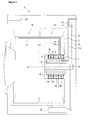
- the washing machine (1) comprises a drum (2) rotated by a motor (M) around the horizontal axis (E), wherein the laundry is placed, a tub (3) wherein the drum (2) moves, a shaft (4) that transfers the movement received from the motor (M) to the drum (2), a hub (5) disposed at the center of the rear wall of the tub (3), which is stationary together with the tub (3) and wherein the shaft (4) is supported, a cylindrical housing (6) disposed at the center of the rear wall of the drum (2), surrounding the hub (5) concentrically and rotating together with the drum (2), more than one ring-shaped gasket (7) placed between the cylindrical inner surface of the housing (6) and the cylindrical outer surface of the hub (5), arranged one after the other and in parallel to each other, the outer edges of which are secured to the inner surface of the housing (6), rotating together with the housing (6) and the inner edges of which contact the cylindrical outer surface of the hub (5) so as to rotate around the hub (5) by rubbing against it, more than one slot (8) disposed between the gaskets
- the washing machine (1) of the present invention comprises
- control unit (12) detects the unbalanced load in the drum (2) and controls the operation of the water inlet valves (11, 111).
- the control unit (12) delivers water through the first water inlet line (13) by opening the first water inlet valve (11) upon detecting unbalance in the first chamber (10), water coming to the slot (8) fills only into the first division (15) by means of the separator (16) and is delivered to the first water distribution line (14) and from there to the first chamber (10) by means of the centrifugal force.
- the control unit (12) delivers water through the second water inlet line (113) by opening the second water inlet valve (111) upon detecting unbalance in the second chamber (110), water coming to the slot (8) fills only into the second division (115) by means of the separator (16) and is delivered to the second water distribution line (114) and from there to the second chamber (110) by means of the centrifugal force.
- a single slot (8) serves as two separate slots (8) by means of the separator (16), the separator (16) almost completely prevents the water passage from one division (15, 115) to the other division (15, 115) and water can be separately delivered to two chambers (10, 110) from each slot (8) by means of the divisions (15, 115).
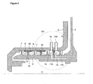
- the separator (16) comprises a ring-shaped rim (17) which is fixed to the cylindrical inner surface of the housing (6) between the gaskets (7) and which rotates together with the housing (6) and a ring-shaped extension (18) which is connected to the inner surface of the rim (17) and which extends, in the radial direction, towards between the water inlet lines (13, 113) opening to the slot (8) such that a gap (G) remains between the cylindrical outer surface of the hub (5) and the extension (18) ( Figure 3 ).
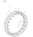
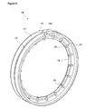
- the separator (16) furthermore, comprises at least two orifices (19, 119) which are disposed on the rim (17), which overlap with the water distribution lines (14, 114) and which rotate together with the housing (6) and the water distribution lines (14, 114), which provide water sticking onto the inner surface of the rim (17) by the effect of the centrifugal force to reach the water distribution lines (14, 114) by passing through the rim (17) in the radial direction ( Figure 3 , Figure 4 , Figure 5 , Figure 6 ).
- the drum baffles (9), the housing (6), the gaskets (7), the slots (8), the distribution lines (14, 114) and the separators (16) rotate together with the drum (2) around the horizontal axis (E).
- the gaskets (7) contact the hub (5), but the separators (16) do not contact the hub (5).
- the control unit (12) When the unbalanced load is detected by the control unit (12), the amount and the position of the unbalanced load and to which chamber (10, 110) in which baffle (9) water should be delivered is determined, then first necessary amount of water is taken from the water mains by operating the water inlet valves (11, 111) and water is delivered by means of the water inlet lines (13, 113) to the division (15, 115) in connection with the chamber (10, 110) wherein the unbalance is detected.
- the separator (16) comprises more than one blade (20) which is connected to the extension (18) in the inner side of the rim (17), which extends into the divisions (15, 115) from both sides of the extension (18), which rotates together with the rim (17) and the extension (18), which increase the speed of water delivered to the water distribution line (14, 114) from the division (15, 115) by increasing the centrifugal force affecting water heading toward the inner surface of the rim (17) during the rotational movement ( Figure 5 , Figure 6 ).
- the blades (20) extend towards the inner surface of the rim (17) in the radial direction at both sides of the extension (18) ( Figure 6 ).
- the blades (20) extend towards the inner surface of the rim (17) in a curved manner in comparison with the radial direction at both sides of the extension (18) ( Figure 5 ).
- the curved blades (20) provide water to be delivered at an increased speed to the inner surface of the rim (17) and to the water distribution line (14, 114) by means of the orifice (19, 119) by increasing the centrifugal force affecting water in the divisions (15, 115) more than the flat blades (20).
- the separator (16) comprises two channels (21) which are formed by cutting-out the portions of the blades (20) near the inner surface of the rim (17) or by producing the blades (20) in recessed form at both sides of the extension (18), which extend all around the inner surface of the rim (17) and which provide water in the division (15, 115) during the rotational movement and the effect of the centrifugal force thereon of which is increased by the blades (20) to reach the orifice (19, 119) on the inner surface of the rim (17) ( Figure 3 , Figure 5 ).
- Water reaching the division (15, 115) through the water inlet line (13, 113) continues its movement in the radial direction and first reaches the blades (20) disposed in the division (15, 115) and then to the channel (21).
- Water reaching the channel (21) applies pressure onto the inner surface of the rim (17) with the effect of the centrifugal force and quickly passes to the water distribution line (14, 114) by means of the orifice (19, 119).
- the separator (16) comprises a groove (22) which extends all around the outer surface of the rim (17) and which, by means of an o-ring mounted thereon, provides the separator (16) to be attached to the inner surface of the housing (6) in a leak-proof manner at the same level with the slots (8) ( Figure 4 , Figure 5 , Figure 6 ).
- water in an amount to compensate the unbalanced load and decrease the effect thereof to a minimum is taken from the mains and delivered to the related divisions (15, 115) in the slots (8) disposed between the gaskets (7) placed at the portion wherein the shaft (4) rotating the drum (2) is supported by means of the water inlet lines (13, 113) and then is transferred to the chambers (10, 110) from the divisions (15, 115) by means of the water distribution lines (14, 114).
- the separator (16) separating each slot (8) into two divisions (15, 115) provides that the chambers (10, 110) are supplied from a single slot (8) almost independently from each other, utilization of separate slots (8) for supplying each chamber (10, 110) is no more required and thus cost is decreased by using fewer number of slots (8) and gaskets (7) in comparison with the state of the art embodiments.
- water in an amount that does not affect the unbalancing process passes from one division (15, 115) to the other division (15, 115) in the slot (8) through the gap (G) between the separator (16) and the hub (5).
- one slot (8) serves as two separate slots (8), two chambers (10, 110) in one drum baffle (9) are supplied from a single slot (8), number of slots (8) and thus of costly gaskets (7) the production of which is difficult is decreased, saving is provided by using fewer number of gaskets (7) instead of a larger number of gaskets (7) and low-cost separators (16).
Landscapes
- Engineering & Computer Science (AREA)
- Textile Engineering (AREA)
- Main Body Construction Of Washing Machines And Laundry Dryers (AREA)
Claims (8)
- Waschmaschine (1), umfassend eine Trommel (2), die von einem Motor um die horizontale Achse gedreht wird, einen Waschbehälter (3), in dem sich die Trommel (2) bewegt, eine Welle (4), die die vom Motor empfangene Bewegung auf die Trommel (2) überträgt, eine Nabe (5), die in der Mitte der Rückwand des Waschbehälters (3) um die horizontale Achse herum angeordnet ist und zusammen mit dem Waschbehälter (3) stationär ist und in der die Welle (4) gelagert ist, ein zylindrisches Gehäuse (6), das in der Mitte der Rückwand der Trommel (2) um die horizontale Achse herum angeordnet ist und die Nabe (5) konzentrisch lagert und sich zusammen mit der Trommel (2) dreht, mehrere ringförmige Dichtungen (7), die zwischen der zylindrischen Innenfläche des Gehäuses (6) und der zylindrischen Außenfläche der Nabe (5) angeordnet sind und eine nach der anderen und parallel zueinander angeordnet sind, mehrere Schlitze (8), die zwischen den Dichtungen (7) angeordnet sind, wenigstens ein Trommelleitblech (9), das an der Innenfläche der Trommel (2) angeordnet ist, mehrere Kammern (10, 110), die im Trommelleitblech (9) angeordnet sind und in die entsprechend des Zustands eines Ladungsungleichgewichts Wasser geleitet wird, wenigstens ein Wassereinlassventil (11, 111), das dafür sorgt, dass Wasser von der Wasserversorgung in der für den Ausgleichvorgang benötigten Menge an die Kammern (10, 110) geleitet wird, eine Steuereinheit (12), die die Wassereinlassventile (11, 111) öffnet/schließt, indem sie die Menge und die Position des Ladungsungleichgewichts bestimmt, wenn das Ladungsungleichgewicht erkannt wird, und bestimmt, wie viel Wasser in welches Leitblech (9) und welche Kammer (10, 110) geleitet werden soll.
dadurch gekennzeichnet, dass- sich wenigstens zwei Wassereinlassleitungen (13, 113) in den Schlitz (8) hinein öffnen, indem sie durch die Nabe (5) verlaufen, und stationär zusammen mit dem Waschbehälter (3) sind, wobei ein Ende davon mit den Wassereinlassventilen (11, 111) und das andere Ende mit dem Schlitz (8) verbunden ist,- wenigstens zwei Wasserverteilungsleitungen (14, 114) vorliegen, von denen ein Ende mit dem Schlitz (8) verbunden ist und das andere Ende mit den Kammern (10, 110), und die dafür sorgen, dass Wasser vom Schlitz (8) an die Kammern (10, 110) geleitet wird,
und- wenigstens eine Trenneinrichtung (16), die zwischen den zwei Dichtungen (7) angeordnet ist und sich in den Schlitz (8) erstreckt, den Schlitz (8) in wenigstens zwei Abteilungen (15, 115) unterteilt und dafür sorgt, dass Wasser von der ersten Wassereinlassleitung (13) an die erste Abteilung (15) und an die erste Wasserverteilungsleitung (14) geleitet wird und Wasser von der zweiten Wassereinlassleitung (113) an die zweite Abteilung (115) und an die zweite Wasserverteilungsleitung (114) geleitet wird, und auf diese Weise dafür sorgt, dass die Kammern (10, 110) nahezu unabhängig voneinander von separaten Abteilungen (15, 115) im selben Schlitz (8) versorgt werden. - Waschmaschine (1) nach Anspruch 1, dadurch gekennzeichnet, dass die Trenneinrichtung (16) einen ringförmigen Rand (17) mit einer Außenfläche aufweist, die an der zylindrischen Innenfläche des Gehäuses (6) zwischen den Dichtungen (7) befestigt ist, und der sich zusammen mit dem Gehäuse (6) dreht, und eine ringförmige Verlängerung (18), die mit der Innenfläche des Randes (17) verbunden ist und sich in radialer Richtung zu einem Bereich zwischen den Wassereinlassleitungen (13, 113), die sich in den Schlitz (8) hinein öffnen, erstreckt, derart, dass ein Spalt (G) zwischen der zylindrischen Außenfläche der Nabe (5) und der Verlängerung (18) verbleibt.
- Waschmaschine (1) nach Anspruch 1 oder 2, dadurch gekennzeichnet, dass die Trenneinrichtung (16) wenigstens zwei Mündungen (19, 119) umfasst, die im Rand (17) angeordnet sind und die Wasserverteilungsleitungen (14, 114) überlagern und dafür sorgen, dass Wasser, das an der Innenfläche des Randes (17) haftet, mittels Zentrifugalkraftwirkung die Wasserverteilungsleitungen (14, 114) erreicht, indem es in radialer Richtung durch den Rand (17) tritt.
- Waschmaschine (1) nach einem der vorangehenden Ansprüche, dadurch gekennzeichnet, dass die Trenneinrichtung (16) mehrere Schaufeln (20) umfasst, die sich von beiden Seiten der Verlängerung (18) an der Innenseite des Randes (17) in die Abteilungen (15, 115) erstrecken und sich zusammen mit dem Rand (17) und der Verlängerung (18) drehen, was die Zentrifugalkraft erhöht, die auf das Wasser einwirkt, das sich während der Drehbewegung zur Innenfläche des Randes (17) bewegt.
- Waschmaschine (1) nach Anspruch 4, dadurch gekennzeichnet, dass bei der Trenneinrichtung (16) die Schaufeln (20) auf beiden Seiten der Verlängerung (18) angeordnet sind und sich in radialer Richtung zur Innenfläche des Randes (17) erstrecken.
- Waschmaschine (1) nach Anspruch 4, dadurch gekennzeichnet, dass bei der Trenneinrichtung (16) die Schaufeln (20) auf beiden Seiten der Verlängerung (18) angeordnet sind und sich im Vergleich zur radialen Richtung auf gekrümmte Weise zur Innenfläche des Randes (17) erstrecken.
- Waschmaschine (1) nach einem der vorangehenden Ansprüche, dadurch gekennzeichnet, dass die Trenneinrichtung (16) zwei Kanäle (21) umfasst, die durch Ausnehmen der Abschnitte der Schaufeln (20) nahe der Innenfläche des Randes (17) oder durch Herstellen der Schaufeln (20) in auf beiden Seiten der Verlängerung (18), die den Abteilungen (15, 115) zugewandt sind, in vertiefter Form, und die sich um die gesamte Innenfläche des Randes (17) herum erstrecken.
- Waschmaschine (1) nach einem der vorangehenden Ansprüche, dadurch gekennzeichnet, dass die Trenneinrichtung (16) eine Nut (22) umfasst, die sich um die gesamte Außenfläche des Randes (17) erstreckt und mittels eines daran angeordneten O-Rings dafür sorgt, dass die Trenneinrichtung (16) auf dichte Weise an der Innenfläche des Gehäuses (6) angebracht ist.
Priority Applications (1)
| Application Number | Priority Date | Filing Date | Title |
|---|---|---|---|
| PL11719283T PL2572025T3 (pl) | 2010-05-20 | 2011-05-16 | Pralka, w której niezbalansowany ładunek jest balansowany |
Applications Claiming Priority (2)
| Application Number | Priority Date | Filing Date | Title |
|---|---|---|---|
| TR201004003 | 2010-05-20 | ||
| PCT/EP2011/057858 WO2011144559A1 (en) | 2010-05-20 | 2011-05-16 | A washing machine wherein the unbalanced load is balanced |
Publications (2)
| Publication Number | Publication Date |
|---|---|
| EP2572025A1 EP2572025A1 (de) | 2013-03-27 |
| EP2572025B1 true EP2572025B1 (de) | 2014-04-16 |
Family
ID=44562706
Family Applications (1)
| Application Number | Title | Priority Date | Filing Date |
|---|---|---|---|
| EP11719283.1A Not-in-force EP2572025B1 (de) | 2010-05-20 | 2011-05-16 | Waschmaschine worin unwucht ist ausgeglichen |
Country Status (6)
| Country | Link |
|---|---|
| US (1) | US9303352B2 (de) |
| EP (1) | EP2572025B1 (de) |
| KR (1) | KR101396249B1 (de) |
| CN (1) | CN102892940B (de) |
| PL (1) | PL2572025T3 (de) |
| WO (1) | WO2011144559A1 (de) |
Families Citing this family (16)
| Publication number | Priority date | Publication date | Assignee | Title |
|---|---|---|---|---|
| ITCS20120007A1 (it) * | 2012-02-21 | 2013-08-22 | Guido Danieli | Terza variante al sistema di controllo delle vibrazioni durante la centrifugazione in una lavatrice domestica |
| KR102032845B1 (ko) | 2013-02-13 | 2019-10-16 | 엘지전자 주식회사 | 의류처리장치 |
| CN104120584B (zh) * | 2013-04-26 | 2018-08-07 | 青岛海尔洗衣机有限公司 | 一种具有主动注水平衡环的洗衣机及控制方法 |
| KR102204614B1 (ko) * | 2014-02-20 | 2021-01-19 | 엘지전자 주식회사 | 의류처리장치 |
| KR102254892B1 (ko) * | 2014-11-03 | 2021-05-24 | 엘지전자 주식회사 | 의류처리장치 및 의류처리장치의 제어방법 |
| CH710591B1 (de) * | 2015-01-06 | 2018-11-30 | V Zug Ag | Waschmaschine mit Unwuchtkompensation und progressiver Lagerung. |
| CH710592A1 (de) * | 2015-01-06 | 2016-07-15 | V Zug Ag | Waschmaschine mit Unwuchtkompensation. |
| CH710593A1 (de) * | 2015-01-06 | 2016-07-15 | V Zug Ag | Hydrauliksystem für Waschmaschine mit Unwuchtkompensation. |
| US9518352B2 (en) * | 2015-01-07 | 2016-12-13 | Haier Us Appliance Solutions, Inc. | Unitary balance ring for a washing machine appliance |
| JP2017113232A (ja) * | 2015-12-24 | 2017-06-29 | 青島海爾洗衣机有限公司QingDao Haier Washing Machine Co.,Ltd. | 洗濯機の制御方法 |
| US10815597B2 (en) * | 2018-05-31 | 2020-10-27 | Whirlpool Corporation | Laundry treating appliance having a liquid distribution assembly |
| US11535969B2 (en) * | 2019-05-29 | 2022-12-27 | Whirlpool Corporation | Fluid delivery system for a front-load washing appliance for delivering fluid to lifters of the drum |
| DE102019208968B3 (de) * | 2019-06-19 | 2020-06-10 | Haier Deutschland GmbH | Waschmaschine und Verfahren zum Ausgleichen einer durch Wäsche verursachten Unwucht |
| EP3862478B1 (de) | 2020-02-10 | 2025-03-05 | The Procter & Gamble Company | Dynamische auswuchtanordnungen und waschvorrichtungen mit einem oder mehreren drehfedern |
| EP3862477B1 (de) * | 2020-02-10 | 2024-08-14 | The Procter & Gamble Company | Waschvorrichtungen mit dynamischen auswuchtanordnungen |
| EP3862479A1 (de) | 2020-02-10 | 2021-08-11 | The Procter & Gamble Company | Aufhängungslose wäschevorrichtungen und verfahren zum auswuchten einer wäschevorrichtung |
Family Cites Families (14)
| Publication number | Priority date | Publication date | Assignee | Title |
|---|---|---|---|---|
| USRE24140E (en) * | 1956-04-10 | Automatic balancing system for rotatable | ||
| US2534267A (en) * | 1945-10-03 | 1950-12-19 | Leo M Kahn | Washing machine cylinder balancing apparatus |
| US2534268A (en) * | 1946-05-31 | 1950-12-19 | Kahn | Washing machine cylinder balancing apparatus |
| US2534269A (en) * | 1948-05-26 | 1950-12-19 | Kahn | Automatic balancing system for cleaning machine cylinders |
| US2975528A (en) * | 1957-11-29 | 1961-03-21 | Gen Motors Corp | Prime mover for clothes drier |
| US5280660A (en) * | 1992-10-05 | 1994-01-25 | Pellerin Milnor Corporation | Centrifugal extracting machine having balancing system |
| US5582040A (en) * | 1995-08-09 | 1996-12-10 | Khan; Aman U. | Water balancing apparatus for horizontal axis and vertical axis laundry appliances |
| DE19859567A1 (de) * | 1998-12-22 | 2000-06-29 | Bsh Bosch Siemens Hausgeraete | Antriebsvorrichtung für eine von vorn beschickbare Waschmaschine |
| JP2002136792A (ja) * | 2000-11-01 | 2002-05-14 | Sanyo Electric Co Ltd | ドラム式洗濯機 |
| JP2002355491A (ja) * | 2001-03-28 | 2002-12-10 | Sanyo Electric Co Ltd | 洗濯機 |
| PL1693500T3 (pl) * | 2005-06-24 | 2015-02-27 | V Zug Ag | Pralka ze zbiornikami dla kompensacji niewyważenia |
| CN101680150B (zh) | 2007-04-17 | 2011-06-22 | 阿塞里克股份有限公司 | 洗涤机/干燥机 |
| CN102187031B (zh) * | 2008-10-16 | 2012-12-05 | 阿塞里克股份有限公司 | 洗涤/烘干机 |
| KR101395619B1 (ko) * | 2009-11-13 | 2014-05-16 | 아세릭 에이. 에스 | 불균형 하중을 균형시키는 세탁기 |
-
2011
- 2011-05-16 CN CN201180025015.8A patent/CN102892940B/zh not_active Expired - Fee Related
- 2011-05-16 PL PL11719283T patent/PL2572025T3/pl unknown
- 2011-05-16 WO PCT/EP2011/057858 patent/WO2011144559A1/en not_active Ceased
- 2011-05-16 EP EP11719283.1A patent/EP2572025B1/de not_active Not-in-force
- 2011-05-16 US US13/699,287 patent/US9303352B2/en not_active Expired - Fee Related
- 2011-05-16 KR KR1020127022525A patent/KR101396249B1/ko not_active Expired - Fee Related
Also Published As
| Publication number | Publication date |
|---|---|
| US20130061639A1 (en) | 2013-03-14 |
| CN102892940B (zh) | 2017-01-11 |
| WO2011144559A1 (en) | 2011-11-24 |
| US9303352B2 (en) | 2016-04-05 |
| CN102892940A (zh) | 2013-01-23 |
| PL2572025T3 (pl) | 2014-09-30 |
| EP2572025A1 (de) | 2013-03-27 |
| KR20120123111A (ko) | 2012-11-07 |
| KR101396249B1 (ko) | 2014-05-19 |
Similar Documents
| Publication | Publication Date | Title |
|---|---|---|
| US9303352B2 (en) | Washing machine wherein the unbalanced load is balanced | |
| US9175430B2 (en) | Washing machine wherein the unbalanced load is balanced | |
| US9187858B2 (en) | Washing machine wherein the unbalanced load is balanced | |
| EP2147142B1 (de) | Waschtrockner | |
| EP2235247B1 (de) | Waschmaschine mit reservoirs in den rippen für ausgleich und waschsprays | |
| EP2362921B1 (de) | Waschtrockner | |
| CN1304468A (zh) | 灵敏的平衡装置 | |
| US20090173110A1 (en) | Washing machine | |
| EP2572027B1 (de) | Waschmaschine mit ausgeglichener asymmetrischer last | |
| EP2499288B1 (de) | Waschmaschine mit ausgeglichener asymmetrischer last | |
| JPH11169595A (ja) | 回転胴のバランス調整装置 | |
| EP3401432A1 (de) | Technik zum ausgleichen während der trommelrotation in einer waschmaschine | |
| EP2572024B1 (de) | Waschmaschine mit einer trommel | |
| JPS6216672B2 (de) | ||
| EP2631342A1 (de) | Wäschetrommel für eine Wäschebehandlungsmaschine |
Legal Events
| Date | Code | Title | Description |
|---|---|---|---|
| PUAI | Public reference made under article 153(3) epc to a published international application that has entered the european phase |
Free format text: ORIGINAL CODE: 0009012 |
|
| 17P | Request for examination filed |
Effective date: 20120628 |
|
| AK | Designated contracting states |
Kind code of ref document: A1 Designated state(s): AL AT BE BG CH CY CZ DE DK EE ES FI FR GB GR HR HU IE IS IT LI LT LU LV MC MK MT NL NO PL PT RO RS SE SI SK SM TR |
|
| DAX | Request for extension of the european patent (deleted) | ||
| GRAP | Despatch of communication of intention to grant a patent |
Free format text: ORIGINAL CODE: EPIDOSNIGR1 |
|
| INTG | Intention to grant announced |
Effective date: 20131209 |
|
| GRAS | Grant fee paid |
Free format text: ORIGINAL CODE: EPIDOSNIGR3 |
|
| GRAA | (expected) grant |
Free format text: ORIGINAL CODE: 0009210 |
|
| AK | Designated contracting states |
Kind code of ref document: B1 Designated state(s): AL AT BE BG CH CY CZ DE DK EE ES FI FR GB GR HR HU IE IS IT LI LT LU LV MC MK MT NL NO PL PT RO RS SE SI SK SM TR |
|
| REG | Reference to a national code |
Ref country code: GB Ref legal event code: FG4D |
|
| REG | Reference to a national code |
Ref country code: CH Ref legal event code: EP |
|
| REG | Reference to a national code |
Ref country code: AT Ref legal event code: REF Ref document number: 662666 Country of ref document: AT Kind code of ref document: T Effective date: 20140515 |
|
| REG | Reference to a national code |
Ref country code: IE Ref legal event code: FG4D |
|
| REG | Reference to a national code |
Ref country code: DE Ref legal event code: R096 Ref document number: 602011006224 Country of ref document: DE Effective date: 20140605 |
|
| REG | Reference to a national code |
Ref country code: AT Ref legal event code: MK05 Ref document number: 662666 Country of ref document: AT Kind code of ref document: T Effective date: 20140416 |
|
| REG | Reference to a national code |
Ref country code: NL Ref legal event code: VDEP Effective date: 20140416 |
|
| REG | Reference to a national code |
Ref country code: LT Ref legal event code: MG4D |
|
| REG | Reference to a national code |
Ref country code: PL Ref legal event code: T3 |
|
| PG25 | Lapsed in a contracting state [announced via postgrant information from national office to epo] |
Ref country code: GR Free format text: LAPSE BECAUSE OF FAILURE TO SUBMIT A TRANSLATION OF THE DESCRIPTION OR TO PAY THE FEE WITHIN THE PRESCRIBED TIME-LIMIT Effective date: 20140717 Ref country code: LT Free format text: LAPSE BECAUSE OF FAILURE TO SUBMIT A TRANSLATION OF THE DESCRIPTION OR TO PAY THE FEE WITHIN THE PRESCRIBED TIME-LIMIT Effective date: 20140416 Ref country code: NL Free format text: LAPSE BECAUSE OF FAILURE TO SUBMIT A TRANSLATION OF THE DESCRIPTION OR TO PAY THE FEE WITHIN THE PRESCRIBED TIME-LIMIT Effective date: 20140416 Ref country code: FI Free format text: LAPSE BECAUSE OF FAILURE TO SUBMIT A TRANSLATION OF THE DESCRIPTION OR TO PAY THE FEE WITHIN THE PRESCRIBED TIME-LIMIT Effective date: 20140416 Ref country code: IS Free format text: LAPSE BECAUSE OF FAILURE TO SUBMIT A TRANSLATION OF THE DESCRIPTION OR TO PAY THE FEE WITHIN THE PRESCRIBED TIME-LIMIT Effective date: 20140816 Ref country code: NO Free format text: LAPSE BECAUSE OF FAILURE TO SUBMIT A TRANSLATION OF THE DESCRIPTION OR TO PAY THE FEE WITHIN THE PRESCRIBED TIME-LIMIT Effective date: 20140716 Ref country code: CY Free format text: LAPSE BECAUSE OF FAILURE TO SUBMIT A TRANSLATION OF THE DESCRIPTION OR TO PAY THE FEE WITHIN THE PRESCRIBED TIME-LIMIT Effective date: 20140416 Ref country code: BG Free format text: LAPSE BECAUSE OF FAILURE TO SUBMIT A TRANSLATION OF THE DESCRIPTION OR TO PAY THE FEE WITHIN THE PRESCRIBED TIME-LIMIT Effective date: 20140716 |
|
| PG25 | Lapsed in a contracting state [announced via postgrant information from national office to epo] |
Ref country code: AT Free format text: LAPSE BECAUSE OF FAILURE TO SUBMIT A TRANSLATION OF THE DESCRIPTION OR TO PAY THE FEE WITHIN THE PRESCRIBED TIME-LIMIT Effective date: 20140416 Ref country code: HR Free format text: LAPSE BECAUSE OF FAILURE TO SUBMIT A TRANSLATION OF THE DESCRIPTION OR TO PAY THE FEE WITHIN THE PRESCRIBED TIME-LIMIT Effective date: 20140416 Ref country code: ES Free format text: LAPSE BECAUSE OF FAILURE TO SUBMIT A TRANSLATION OF THE DESCRIPTION OR TO PAY THE FEE WITHIN THE PRESCRIBED TIME-LIMIT Effective date: 20140416 Ref country code: LV Free format text: LAPSE BECAUSE OF FAILURE TO SUBMIT A TRANSLATION OF THE DESCRIPTION OR TO PAY THE FEE WITHIN THE PRESCRIBED TIME-LIMIT Effective date: 20140416 Ref country code: RS Free format text: LAPSE BECAUSE OF FAILURE TO SUBMIT A TRANSLATION OF THE DESCRIPTION OR TO PAY THE FEE WITHIN THE PRESCRIBED TIME-LIMIT Effective date: 20140416 Ref country code: SE Free format text: LAPSE BECAUSE OF FAILURE TO SUBMIT A TRANSLATION OF THE DESCRIPTION OR TO PAY THE FEE WITHIN THE PRESCRIBED TIME-LIMIT Effective date: 20140416 |
|
| PG25 | Lapsed in a contracting state [announced via postgrant information from national office to epo] |
Ref country code: PT Free format text: LAPSE BECAUSE OF FAILURE TO SUBMIT A TRANSLATION OF THE DESCRIPTION OR TO PAY THE FEE WITHIN THE PRESCRIBED TIME-LIMIT Effective date: 20140818 |
|
| REG | Reference to a national code |
Ref country code: CH Ref legal event code: PL |
|
| REG | Reference to a national code |
Ref country code: DE Ref legal event code: R097 Ref document number: 602011006224 Country of ref document: DE |
|
| PG25 | Lapsed in a contracting state [announced via postgrant information from national office to epo] |
Ref country code: LI Free format text: LAPSE BECAUSE OF NON-PAYMENT OF DUE FEES Effective date: 20140531 Ref country code: CZ Free format text: LAPSE BECAUSE OF FAILURE TO SUBMIT A TRANSLATION OF THE DESCRIPTION OR TO PAY THE FEE WITHIN THE PRESCRIBED TIME-LIMIT Effective date: 20140416 Ref country code: DK Free format text: LAPSE BECAUSE OF FAILURE TO SUBMIT A TRANSLATION OF THE DESCRIPTION OR TO PAY THE FEE WITHIN THE PRESCRIBED TIME-LIMIT Effective date: 20140416 Ref country code: BE Free format text: LAPSE BECAUSE OF FAILURE TO SUBMIT A TRANSLATION OF THE DESCRIPTION OR TO PAY THE FEE WITHIN THE PRESCRIBED TIME-LIMIT Effective date: 20140416 Ref country code: CH Free format text: LAPSE BECAUSE OF NON-PAYMENT OF DUE FEES Effective date: 20140531 Ref country code: SK Free format text: LAPSE BECAUSE OF FAILURE TO SUBMIT A TRANSLATION OF THE DESCRIPTION OR TO PAY THE FEE WITHIN THE PRESCRIBED TIME-LIMIT Effective date: 20140416 Ref country code: MC Free format text: LAPSE BECAUSE OF FAILURE TO SUBMIT A TRANSLATION OF THE DESCRIPTION OR TO PAY THE FEE WITHIN THE PRESCRIBED TIME-LIMIT Effective date: 20140416 Ref country code: EE Free format text: LAPSE BECAUSE OF FAILURE TO SUBMIT A TRANSLATION OF THE DESCRIPTION OR TO PAY THE FEE WITHIN THE PRESCRIBED TIME-LIMIT Effective date: 20140416 Ref country code: RO Free format text: LAPSE BECAUSE OF FAILURE TO SUBMIT A TRANSLATION OF THE DESCRIPTION OR TO PAY THE FEE WITHIN THE PRESCRIBED TIME-LIMIT Effective date: 20140416 |
|
| PLBE | No opposition filed within time limit |
Free format text: ORIGINAL CODE: 0009261 |
|
| STAA | Information on the status of an ep patent application or granted ep patent |
Free format text: STATUS: NO OPPOSITION FILED WITHIN TIME LIMIT |
|
| REG | Reference to a national code |
Ref country code: IE Ref legal event code: MM4A |
|
| 26N | No opposition filed |
Effective date: 20150119 |
|
| PG25 | Lapsed in a contracting state [announced via postgrant information from national office to epo] |
Ref country code: IE Free format text: LAPSE BECAUSE OF NON-PAYMENT OF DUE FEES Effective date: 20140516 |
|
| REG | Reference to a national code |
Ref country code: DE Ref legal event code: R097 Ref document number: 602011006224 Country of ref document: DE Effective date: 20150119 |
|
| PG25 | Lapsed in a contracting state [announced via postgrant information from national office to epo] |
Ref country code: SI Free format text: LAPSE BECAUSE OF FAILURE TO SUBMIT A TRANSLATION OF THE DESCRIPTION OR TO PAY THE FEE WITHIN THE PRESCRIBED TIME-LIMIT Effective date: 20140416 |
|
| PG25 | Lapsed in a contracting state [announced via postgrant information from national office to epo] |
Ref country code: MT Free format text: LAPSE BECAUSE OF FAILURE TO SUBMIT A TRANSLATION OF THE DESCRIPTION OR TO PAY THE FEE WITHIN THE PRESCRIBED TIME-LIMIT Effective date: 20140416 |
|
| PG25 | Lapsed in a contracting state [announced via postgrant information from national office to epo] |
Ref country code: SM Free format text: LAPSE BECAUSE OF FAILURE TO SUBMIT A TRANSLATION OF THE DESCRIPTION OR TO PAY THE FEE WITHIN THE PRESCRIBED TIME-LIMIT Effective date: 20140416 |
|
| REG | Reference to a national code |
Ref country code: FR Ref legal event code: PLFP Year of fee payment: 6 |
|
| PG25 | Lapsed in a contracting state [announced via postgrant information from national office to epo] |
Ref country code: HU Free format text: LAPSE BECAUSE OF FAILURE TO SUBMIT A TRANSLATION OF THE DESCRIPTION OR TO PAY THE FEE WITHIN THE PRESCRIBED TIME-LIMIT; INVALID AB INITIO Effective date: 20110516 Ref country code: LU Free format text: LAPSE BECAUSE OF NON-PAYMENT OF DUE FEES Effective date: 20140516 |
|
| REG | Reference to a national code |
Ref country code: FR Ref legal event code: PLFP Year of fee payment: 7 |
|
| PGFP | Annual fee paid to national office [announced via postgrant information from national office to epo] |
Ref country code: TR Payment date: 20170327 Year of fee payment: 7 |
|
| PGFP | Annual fee paid to national office [announced via postgrant information from national office to epo] |
Ref country code: GB Payment date: 20170519 Year of fee payment: 7 Ref country code: FR Payment date: 20170523 Year of fee payment: 7 Ref country code: DE Payment date: 20170523 Year of fee payment: 7 |
|
| PGFP | Annual fee paid to national office [announced via postgrant information from national office to epo] |
Ref country code: PL Payment date: 20170511 Year of fee payment: 7 Ref country code: IT Payment date: 20170526 Year of fee payment: 7 |
|
| PG25 | Lapsed in a contracting state [announced via postgrant information from national office to epo] |
Ref country code: MK Free format text: LAPSE BECAUSE OF FAILURE TO SUBMIT A TRANSLATION OF THE DESCRIPTION OR TO PAY THE FEE WITHIN THE PRESCRIBED TIME-LIMIT Effective date: 20140416 |
|
| PG25 | Lapsed in a contracting state [announced via postgrant information from national office to epo] |
Ref country code: AL Free format text: LAPSE BECAUSE OF FAILURE TO SUBMIT A TRANSLATION OF THE DESCRIPTION OR TO PAY THE FEE WITHIN THE PRESCRIBED TIME-LIMIT Effective date: 20140416 |
|
| REG | Reference to a national code |
Ref country code: DE Ref legal event code: R119 Ref document number: 602011006224 Country of ref document: DE |
|
| GBPC | Gb: european patent ceased through non-payment of renewal fee |
Effective date: 20180516 |
|
| PG25 | Lapsed in a contracting state [announced via postgrant information from national office to epo] |
Ref country code: DE Free format text: LAPSE BECAUSE OF NON-PAYMENT OF DUE FEES Effective date: 20181201 Ref country code: FR Free format text: LAPSE BECAUSE OF NON-PAYMENT OF DUE FEES Effective date: 20180531 Ref country code: IT Free format text: LAPSE BECAUSE OF NON-PAYMENT OF DUE FEES Effective date: 20180516 Ref country code: GB Free format text: LAPSE BECAUSE OF NON-PAYMENT OF DUE FEES Effective date: 20180516 |
|
| PG25 | Lapsed in a contracting state [announced via postgrant information from national office to epo] |
Ref country code: PL Free format text: LAPSE BECAUSE OF NON-PAYMENT OF DUE FEES Effective date: 20180516 |
|
| PG25 | Lapsed in a contracting state [announced via postgrant information from national office to epo] |
Ref country code: TR Free format text: LAPSE BECAUSE OF NON-PAYMENT OF DUE FEES Effective date: 20180516 |