EP2572027B1 - Waschmaschine mit ausgeglichener asymmetrischer last - Google Patents
Waschmaschine mit ausgeglichener asymmetrischer last Download PDFInfo
- Publication number
- EP2572027B1 EP2572027B1 EP11733598.4A EP11733598A EP2572027B1 EP 2572027 B1 EP2572027 B1 EP 2572027B1 EP 11733598 A EP11733598 A EP 11733598A EP 2572027 B1 EP2572027 B1 EP 2572027B1
- Authority
- EP
- European Patent Office
- Prior art keywords
- valve
- drum
- washing machine
- water
- tub
- Prior art date
- Legal status (The legal status is an assumption and is not a legal conclusion. Google has not performed a legal analysis and makes no representation as to the accuracy of the status listed.)
- Not-in-force
Links
- 238000005406 washing Methods 0.000 title claims description 42
- XLYOFNOQVPJJNP-UHFFFAOYSA-N water Substances O XLYOFNOQVPJJNP-UHFFFAOYSA-N 0.000 claims description 65
- 230000001960 triggered effect Effects 0.000 claims description 8
- 238000000034 method Methods 0.000 claims description 6
- 230000005355 Hall effect Effects 0.000 claims description 3
- 230000003247 decreasing effect Effects 0.000 description 6
- 230000007423 decrease Effects 0.000 description 4
- 238000001035 drying Methods 0.000 description 2
- 230000000694 effects Effects 0.000 description 2
- 238000004519 manufacturing process Methods 0.000 description 2
- 239000000463 material Substances 0.000 description 2
- 238000007789 sealing Methods 0.000 description 2
- 230000002411 adverse Effects 0.000 description 1
- 239000002184 metal Substances 0.000 description 1
Images

Classifications
-
- D—TEXTILES; PAPER
- D06—TREATMENT OF TEXTILES OR THE LIKE; LAUNDERING; FLEXIBLE MATERIALS NOT OTHERWISE PROVIDED FOR
- D06F—LAUNDERING, DRYING, IRONING, PRESSING OR FOLDING TEXTILE ARTICLES
- D06F37/00—Details specific to washing machines covered by groups D06F21/00 - D06F25/00
- D06F37/20—Mountings, e.g. resilient mountings, for the rotary receptacle, motor, tub or casing; Preventing or damping vibrations
- D06F37/22—Mountings, e.g. resilient mountings, for the rotary receptacle, motor, tub or casing; Preventing or damping vibrations in machines with a receptacle rotating or oscillating about a horizontal axis
- D06F37/225—Damping vibrations by displacing, supplying or ejecting a material, e.g. liquid, into or from counterbalancing pockets
Definitions
- the present invention relates to a washing machine wherein the unbalanced load inside the drum is balanced by using water.
- the washing process is performed by the drum being rotated at different speeds. While the drum is being rotated, an uneven load distribution occurs as a result of the laundry piling up at some areas. Especially in the spin-drying step wherein the drum is rotated at high speeds, the unbalanced load resulting from the laundry and structural factors increases vibration and noise, and causes the washing machine to wear out. Furthermore, the spin-drying performance of the washing machine is adversely affected.
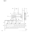
- water taken from the outside for the balancing operation is generally transferred to the chambers on the drum baffles by being passed through the hub of the drum and the tub where the shaft rotating the drum is supported. Water taken from the mains is delivered to the slots between the sealing elements placed in a sequence at the hub portion wherein the shaft is supported.
- the washing machine realized in order to attain the aim of the present invention, explicated in the first claim and the respective claims thereof comprises at least one baffle which has two balancing chambers at the front and rear thereof into which water is delivered in order to balance the unbalanced load occurring in the drum and at least one multiple-way valve rotating together with the drum, having an inlet channel and more than one outlet channel, directing water received from the inlet channel to the desired balancing chambers by means of the outlet channels.
- Water taken from the mains for the balancing process in the washing machine is transferred to the tub hub where the shaft rotating the drum is supported by means of the water inlet line which is stationary together with the tub.
- the hub of the tub is concentrically surrounded by a housing located at the drum rear wall.
- the ring-shaped gaskets rotating together with the housing are placed in sequence between the hub and the housing, and the slots are disposed between the gaskets.
- the inlet channel of the valve is connected to the slot and the outlet channels are connected to the balancing chambers by means of the distribution lines, and more than one balancing chamber at one baffle is supplied from the same slot by means of the multiple-way valve.
- the valve is of electromagnetic-type and comprises a body on which the inlet channel and the outlet channels are disposed and a piston-type magnet which closes one outlet channel by moving therein and which allows water discharge from the other outlet channel.
- the washing machine comprises at least one magnetic coil which is mounted onto the rear wall of the tub so as to be opposite to the valve, which is stationary together with the tub, which has no mechanical connection with the valve, which is magnetized by the control unit applying electric current and which triggers the valve by means of the magnetic field it produces.
- the washing machine comprises more than one valve which is connected to the periphery of the housing on the drum rear wall and which rotates by following a circular course with the rotation of the drum and a single magnetic coil which is connected to the tub rear wall, which is stationary together with the tub and which is commonly used by all the valves.
- the washing machine comprises a preferably "hall effect” type position sensor which is placed near the magnetic coil at the rear wall of the tub and which detects if the valves are aligned with the magnetic coil during their rotation together with the drum in the tub.
- the position sensor produces different voltage values for each valve rotating by following the same course in order to distinguish the valves from each other and thus gives the control unit the information as to which valve should be triggered.
- the washing machine comprises more than one valve connected to the periphery of the housing on the drum rear wall at different radii and thus rotating by following different circle-shaped courses and magnetic coils with the same number as the valves, connected to the tub rear wall so that each thereof aligns with a single valve.
- water in an amount that compensates the unbalanced load and decreases the effect to minimum is taken from the mains and delivered to the slots between the gaskets placed at the portion where the shaft rotating the drum is supported and transferred to the balancing chambers on the baffles from the slots.
- the valve connected to each slot more than one chamber at one baffle is supplied by means of a single slot and saving is provided by decreasing the number of costly gaskets the production process of which is difficult.
- the laundry loading capacity of the drum is increased.
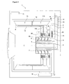
- the washing machine (1) comprises a drum (2) rotated by a motor (M) around the horizontal axis (E), wherein the laundry is placed, a tub (3) wherein the drum (2) moves, a shaft (4) that transfers the movement received from the motor (M) to the drum (2), a hub (5) disposed at the center of the rear wall of the tub (3), which is stationary together with the tub (3) and wherein the shaft (4) is supported, at least one baffle (6) disposed at the cylindrical inner surface of the drum (2), which provides the tumbling of the laundry and wherein water is transferred in case of an unbalanced load, a cylindrical housing (7) disposed at the center of the rear wall of the drum (2), surrounding the hub (5) concentrically such that there remains a gap therebetween and rotating together with the drum (2), more than one ring-shaped gasket (8) arranged one after the other and in parallel to each other in the gap between the housing (7) and the hub (5), the outer edges of which are secured to the inner surface of the housing (7), rotating together with the housing (7) and
- the washing machine (1) of the present invention comprises at least one valve (18) which
- valve (18) is of multiple-way type and mounted onto the periphery of the housing (7) and rotates together with the drum (2).
- the valve (18) has one inlet channel (16) and two outlet channels (17, 117), and the inlet channel (16) is connected to the slot (9), the first outlet channel (17) to the first distribution line (14) and the second outlet channel (117) to the second distribution line (114).
- the control unit (15) detects the unbalanced load during the movement of the drum (2) and controls the operation of the valve (18).
- the control unit (15) provides the valve (18) to deliver water taken from the slot (9) to the first chamber (13) by means of the first outlet channel (17) and the first distribution line (14) or to the second chamber (113) by means of the second outlet channel (117) and the second distribution line (114) according to the unbalanced load status.
- the baffles (6), the housing (7), the slots (9), the distribution lines (14, 114) and the valves (18) rotate together with the drum (2) around the horizontal axis (E).
- the control unit (15) the amount and the position of the unbalanced load and to which baffle (6) water should be delivered is determined, then first the necessary amount of water is taken from the water mains by operating the water inlet valves (11) and water is delivered by means of the water inlet line (10) to the slot (9) in connection with the baffle (6) wherein the unbalance is detected.
- the embodiment of the present invention is activated and the control unit (15) decides whether water should be delivered to the first chamber (13) or the second chamber (113) supplied by the same slot (9) according to the unbalanced load status.
- the control unit (15) decides that water should be delivered to the first chamber (13)
- it provides the valve (18) to open the first outlet channel (17) connected to the first distribution line (14).
- the control unit (15) detects that water should be delivered to the second chamber (113), it provides the valve (18) to open the second outlet channel (117) connected to the second distribution line (114).
- the valve (18) provides that the first chamber (13) or the second chamber (113) is supplied by a single slot (9), utilization of separate slots (9) for supplying each chamber (13, 113) is no more required and thus cost is decreased by using fewer number of slots (9) and gaskets (8) in comparison with the state of the art embodiments.
- the valve (18) is of electromagnetic-type and comprises a body (19) on which the inlet channel (16) and the outlet channels (17, 117) are disposed and a piston-type magnet (20) which closes one outlet channel (17, 117) by moving in the body (19) and which allows water discharge from the other outlet channel (17, 117).
- the washing machine (1) comprises at least one magnetic coil (21) which is mounted onto the rear wall of the tub (3) so as to be opposite to the valve (18), which is stationary together with the tub (3), which has no mechanical connection with the valve (18), which is magnetized by the control unit (15) by applying electric current and which provides the magnet (20) to open/close the outlet channels (17, 117) by remotely triggering the valve (18) rotating together with the drum (2) when the valve (18) is aligned by means of the magnetic field the magnetic coil (21) produces.
- the magnetic coil (21) forms a magnetic field and the valve (18) rotating together with the drum (2) is triggered when aligned with the magnetic coil (21), the magnet (20) in the valve (18) moves forwards or backwards in the body (19) according to the magnetic field applied by the magnetic coil (21).
- the magnetic coil (21) to which electric current is applied by the control unit (15) tries to push or pull the magnet (20) in the body (19) according to the direction of the electric current applied.
- the magnet (20) moving inside the body (19) provides water to be delivered to the first chamber (13) or the second chamber (113) by opening one outlet channel (17, 117) and closing the other outlet channel (17, 117).
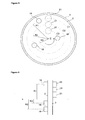
- the washing machine (1) comprises more than one valve (18) connected to the periphery of the housing (7) and rotating by following a semi-circular course (C) with a radius of (R) with the rotation of the drum (2) and a single magnetic coil (21) connected to the tub (3) rear wall, stationary together with the tub (3) and commonly used for all the valves (18) and a preferably "hall effect" type position sensor (22) placed near to the magnetic coil (21) at the tub (3) rear wall and detecting if the valves (18) are aligned with the magnetic coil (21) during the rotation ( Figure 3, Figure 4 ).
- valves (18) rotating together with the drum (2) and the rotating paths of which forms a circular course (C) passes by the stationary magnetic coil (21) in turn and the position sensor (22) detects if the valves (18) are aligned with the magnetic coil (21).
- the control unit (15) applies electric current to the magnetic coil (21) when the valve (18) connected to the said baffle (6) is aligned with the magnetic coil (21) and the valve (18) is triggered and delivers water to the desired chamber (13, 113).
- the position sensor (22) sends the information as to which valve (18) should be triggered to the control unit (15) by producing different voltage values for each valve (18), which provide to differentiate more than one valve (18) rotating the same course (C).
- the control unit (15) when the valve (18) corresponding to the baffle (6) which needs balancing is aligned with the magnetic coil (21), operates the valve (18) by applying current to the magnetic coil (21).
- the washing machine (1) comprises more than one valve (18) which is connected to the periphery of the housing (7) at different distances from each other in the radial direction in reference to the horizontal axis (E) and thus which rotate by following different courses (C1, C2, C3, ...) at radii (R1, R2, R3, ...) different from each other and magnetic coils (21) in a number as many as the number of the valves (18), which are connected to the tub (3) rear wall at different distances perpendicular to the horizontal axis (E) such that each thereof is opposite to a single valve (18) ( Figure 5, Figure 6 ).
- the control unit (15) applies current to the magnetic coil (21) corresponding to the valve (18) that is triggered.
- Each magnetic coil (21) affects only the valve (18) that it corresponds to in terms of the position thereof and not the other valves (18). Due to the different courses (C1, C2, C3, ...) that the valves (18) follow, the need to detect and differentiate different valves (18) passing by a magnetic coil (21) is eliminated, thus the control unit (15) does not need a position sensor (22) in order to apply current to the magnetic coil (21).
- the control unit (15) applies electric current for a certain period of time to the magnetic coil (21) corresponding to the baffle (6) the chambers (13, 113) of which will be supplied with water without waiting it to align with the valve (18) and the related valve (18) performs its function, during the rotation thereof, by being triggered at the moment it passes by the magnetic coil (21) forming a magnetic field beforehand.
- the washing machine (1) comprises 3 baffles (6) placed around the rotational axis (E) at 120 degree-gaps, 6 chambers (13, 113) 4 gaskets (8) arranged in order between the housing (7) and the hub (5), 3 slots (9) disposed between the gaskets (8) and each of which is connected to a baffle (6) and 3 valves (18) connected to the said 3 slots (9) and guiding water received from the slots (9) to the chambers (13, 113).
- Each valve (18) provides each chamber (13 or 113) to be supplied from the same slot (9) by means of the two outlet channels (17), 3 slots (9) and 4 gaskets (8) are used for 6 chambers (13, 113) instead of 6 slots (9) and 7 gaskets (8) proposed in the state of the art and thus number of gaskets (8) and slots (9) is decreased.
Landscapes
- Engineering & Computer Science (AREA)
- Textile Engineering (AREA)
- Control Of Washing Machine And Dryer (AREA)
- Main Body Construction Of Washing Machines And Laundry Dryers (AREA)
Claims (11)
- Waschmaschine (1), umfassend eine Trommel (2), die von einem Motor um die horizontale Achse gedreht wird und in die Wäsche gegeben wird, einen Waschbehälter (3), in dem sich die Trommel (2) bewegt, eine Welle (4), die die Bewegung vom Motor auf die Trommel (2) überträgt, eine Nabe (5), die in der Mitte der Rückwand des Waschbehälters (3) angeordnet ist und zusammen mit dem Waschbehälter (3) stationär ist und in der die Welle (4) getragen wird, wenigstens ein Prallblech (6), das an der Innenfläche der Trommel (2) angeordnet ist und in das im Falle einer Unwucht Wasser geleitet wird, ein zylindrisches Gehäuse (7) das in der Mitte der Rückwand der Trommel (2) angeordnet ist und die Nabe (5) konzentrisch umgibt, derart, dass ein Spalt dazwischen verbleibt, und sich zusammen mit der Trommel (2) dreht, mehrere ringförmige Dichtungen (8), die eine nach der anderen und parallel zueinander in dem Spalt zwischen dem Gehäuse (7) und der Nabe (5) angeordnet sind, mehrere Schlitze (9), die zwischen den Dichtungen angeordnet sind (8), wenigstens eine Wassereinlassleitung (10), die dafür sorgt, dass Wasser für den Auswuchtungsprozess der Unwucht vom Wasserversorgungsnetz an den Schlitz (9) geleitet wird, und deren eines Ende mit dem Wasserversorgungsnetz und deren anderes Ende mit dem Schlitz (9) verbunden ist und die zusammen mit dem Waschbehälter (3) stationär ist, wenigstens ein Trennelement (12), das im Innenbereich des Prallblechs (6) angeordnet ist und das Innenvolumen des Prallblechs (6) in zwei oder mehr Teile teilt, wenigstens zwei Kammern (13, 113), die im Prallblech (6) angeordnet sind und in denen entsprechend dem Unwuchtstatus Wasser geleitet wird und die das Trennelement (12) voneinander teilt, wenigstens zwei Verteilungsleitungen (14, 114), die dafür sorgen, dass Wasser von dem Schlitz (9) in die zwei Kammern (13, 113) geleitet wird, eine Steuereinheit (15), die Wassereinlassventile (11) öffnet/schließt, indem sie die Menge und Position der Unwucht bestimmt, wenn eine Unwucht erkannt wird, und bestimmt, wie viel Wasser in welches Prallblech (6) und welche Kammer (13, 113) geleitet werden soll,
gekennzeichnet durch- wenigstens ein Ventil (18), das am Auslass des Schlitzes (9) angeordnet ist und mit den Verteilungsleitungen (14, 114) verbunden ist und Wasser vom Schlitz (9) an die erste Kammer (13) oder die zweite Kammer (113) im Prallblech (6) lenkt, wenn die Steuereinheit (15) eine Unwucht erkennt, und dadurch dafür sorgt, dass die Kammern (13, 113) im Prallblech (6) durch denselben Schlitz (9) versorgt werden. - Waschmaschine (1) nach Anspruch 1, dadurch gekennzeichnet, dass das Ventil (18) ein Mehrwegeventil (18) ist, das am Umfang des Gehäuses (7) angebracht ist und sich zusammen mit der Trommel (2) dreht.
- Waschmaschine (1) nach Anspruch 1 oder 2, dadurch gekennzeichnet, dass das Ventil (18) einen Einlasskanal (16) und zwei Auslasskanäle (17, 117) aufweist, wobei der Einlasskanal (16) mit dem Schlitz (9), der erste Auslasskanal (17) mit der ersten Verteilungsleitung (14) und der zweite Auslasskanal (117) mit der zweiten Verteilungsleitung (114) verbunden ist.
- Waschmaschine (1) nach einem der vorangehenden Ansprüche, dadurch gekennzeichnet, dass das elektromagnetische Ventil (18) einen Körper (19), an dem der Einlasskanal (16) und die Auslasskanäle (17, 117) angeordnet sind, und einen Magnet (20) umfasst, der einen Auslasskanal (17, 117) schließt, indem er sich im Körper (19) bewegt, und das Ablassen von Wasser aus dem Auslasskanal (17, 117) zulässt.
- Waschmaschine (1) nach Anspruch 4, gekennzeichnet durch wenigstens eine Magnetspule (21), die an der Rückwand des Waschbehälters (3) angebracht ist, derart, dass sie gegenüber dem Ventil (18) ist, zusammen mit dem Waschbehälter stationär ist (3) und durch die Steuereinheit (15) magnetisiert wird, indem elektrischer Strom angelegt wird, und das Ventil (18) ansteuert, das sich zusammen mit der Trommel (2) dreht, wenn das Ventil (18) durch das Magnetfeld ausgerichtet wird, das die Magnetspule (21) erzeugt.
- Waschmaschine (1) nach Anspruch 5, dadurch gekennzeichnet, dass mehrere Ventile (18) mit dem Umfang des Gehäuses (7) verbunden sind und sich drehen, indem sie einem halbkreisförmigen Weg (C) mit einem Radius von (R) mit der Drehung der Trommel (2) folgen, und eine einzelne Magnetspule (21) mit der Rückwand des Waschbehälters (3) verbunden ist und zusammen mit dem Waschbehälter (3) stationär ist und für alle Ventile (18) gemeinsam benutzt wird.
- Waschmaschine (1) nach Anspruch 5 oder 6, gekennzeichnet durch einen Positionssensor (22), der in der Nähe der Magnetspule (21) an der Rückwand des Waschbehälters (3) angeordnet ist und erkennt, ob die Ventile (18) während der Drehung an der Magnetspule (21) ausgerichtet sind.
- Waschmaschine (1) nach Anspruch 7, dadurch gekennzeichnet, dass der Positionssensor (22) an die Steuereinheit (15) die Information dazu sendet, welches Ventil (18) angesteuert werden soll, indem er unterschiedliche Spannungswerte für jedes Ventil (18) erzeugt, das sich dreht, indem es demselben Weg (C) folgt.
- Waschmaschine (1) nach Anspruch 7 oder 8, dadurch gekennzeichnet, dass der Positionssensor (22) ein Hall-Positionssensor (22) ist.
- Waschmaschine (1) nach Anspruch 5, dadurch gekennzeichnet, dass mehrere Ventile (18) in unterschiedlichen Abständen voneinander in radialer Richtung in Bezug auf die horizontale Achse (E) mit dem Gehäuse (7) verbunden sind und sich somit drehen, indem sie unterschiedlichen Wegen (C1, C2, C3, ...) in zueinander unterschiedlichen Radien (R1, R2, R3, ...) folgen, und Magnetspulen (21) in gleicher Anzahl wie die Ventile (18) vorliegen und derart mit der Rückwand des Waschbehälters (3) verbunden sind, dass jede davon gegenüber einem einzelnen Ventil (18) ist.
- Waschmaschine (1) nach einem der vorangehenden Ansprüche, gekennzeichnet durch 3 Prallbleche (6), die mit Abständen von 120 Grad um die Rotationsachse (E) angeordnet sind, 6 Kammern (13, 113), 4 Dichtungen (8), die der Reihe nach zwischen dem Gehäuse (7) und der Nabe (5) angeordnet sind, 3 Schlitze (9), die zwischen den Dichtungen (8) angeordnet sind und jeweils mit einem Prallblech (6) verbunden sind, und 3 Ventile (18), die mit den 3 Schlitzen (9) verbunden sind und Wasser von den Schlitzen (9) an die Kammern (13, 113) lenken.
Applications Claiming Priority (2)
| Application Number | Priority Date | Filing Date | Title |
|---|---|---|---|
| TR201004002 | 2010-05-20 | ||
| PCT/EP2011/057854 WO2011144558A1 (en) | 2010-05-20 | 2011-05-16 | A washing machine wherein the unbalanced load is balanced |
Publications (2)
| Publication Number | Publication Date |
|---|---|
| EP2572027A1 EP2572027A1 (de) | 2013-03-27 |
| EP2572027B1 true EP2572027B1 (de) | 2015-08-05 |
Family
ID=44628640
Family Applications (1)
| Application Number | Title | Priority Date | Filing Date |
|---|---|---|---|
| EP11733598.4A Not-in-force EP2572027B1 (de) | 2010-05-20 | 2011-05-16 | Waschmaschine mit ausgeglichener asymmetrischer last |
Country Status (2)
| Country | Link |
|---|---|
| EP (1) | EP2572027B1 (de) |
| WO (1) | WO2011144558A1 (de) |
Cited By (1)
| Publication number | Priority date | Publication date | Assignee | Title |
|---|---|---|---|---|
| US11053623B2 (en) | 2019-01-23 | 2021-07-06 | Haier Us Appliance Solutions, Inc. | Methods of operating balancing systems of washing machine appliances with motion sensors |
Families Citing this family (2)
| Publication number | Priority date | Publication date | Assignee | Title |
|---|---|---|---|---|
| KR102032845B1 (ko) * | 2013-02-13 | 2019-10-16 | 엘지전자 주식회사 | 의류처리장치 |
| CN104120583B (zh) * | 2013-04-26 | 2017-10-24 | 青岛海尔洗衣机有限公司 | 一种具有注水口式平衡环的洗衣机及控制方法 |
Family Cites Families (4)
| Publication number | Priority date | Publication date | Assignee | Title |
|---|---|---|---|---|
| GB605731A (en) * | 1945-11-28 | 1948-07-29 | George Thilmeyer Hemmeter | Improvements in or relating to dynamically self-balancing units and an extractor employing the same |
| JP2002136792A (ja) | 2000-11-01 | 2002-05-14 | Sanyo Electric Co Ltd | ドラム式洗濯機 |
| CN101680150B (zh) | 2007-04-17 | 2011-06-22 | 阿塞里克股份有限公司 | 洗涤机/干燥机 |
| CN102187031B (zh) * | 2008-10-16 | 2012-12-05 | 阿塞里克股份有限公司 | 洗涤/烘干机 |
-
2011
- 2011-05-16 EP EP11733598.4A patent/EP2572027B1/de not_active Not-in-force
- 2011-05-16 WO PCT/EP2011/057854 patent/WO2011144558A1/en not_active Ceased
Cited By (1)
| Publication number | Priority date | Publication date | Assignee | Title |
|---|---|---|---|---|
| US11053623B2 (en) | 2019-01-23 | 2021-07-06 | Haier Us Appliance Solutions, Inc. | Methods of operating balancing systems of washing machine appliances with motion sensors |
Also Published As
| Publication number | Publication date |
|---|---|
| WO2011144558A1 (en) | 2011-11-24 |
| EP2572027A1 (de) | 2013-03-27 |
Similar Documents
| Publication | Publication Date | Title |
|---|---|---|
| EP2572025B1 (de) | Waschmaschine worin unwucht ist ausgeglichen | |
| EP2759628B1 (de) | Waschmaschine | |
| US9121126B2 (en) | Washing machine and control method thereof | |
| EP2572026B1 (de) | Waschmaschine mit auswuchten einer waschladung | |
| US9605370B2 (en) | Washing machine having dual-drum and assembly method thereof | |
| EP2147142B1 (de) | Waschtrockner | |
| CN1304468A (zh) | 灵敏的平衡装置 | |
| EP2519672A1 (de) | Waschmaschine mit ausgeglichener asymmetrischer last | |
| EP2572027B1 (de) | Waschmaschine mit ausgeglichener asymmetrischer last | |
| EP2362921B1 (de) | Waschtrockner | |
| US10683600B2 (en) | Washing machine | |
| EP2759629B1 (de) | Waschmaschine | |
| KR20150052454A (ko) | 밸런서 및 이를 갖는 세탁기 | |
| US20050194848A1 (en) | BLDC Motor | |
| KR101250244B1 (ko) | 세탁기 | |
| EP2572024B1 (de) | Waschmaschine mit einer trommel | |
| KR101870720B1 (ko) | 세탁기의 운전 및 제어방법 | |
| KR20130044753A (ko) | 세탁기 및 세탁기의 드럼 조립방법 | |
| KR20160117949A (ko) | 의류처리장치 및 의류처리장치의 제어방법 |
Legal Events
| Date | Code | Title | Description |
|---|---|---|---|
| PUAI | Public reference made under article 153(3) epc to a published international application that has entered the european phase |
Free format text: ORIGINAL CODE: 0009012 |
|
| 17P | Request for examination filed |
Effective date: 20120628 |
|
| AK | Designated contracting states |
Kind code of ref document: A1 Designated state(s): AL AT BE BG CH CY CZ DE DK EE ES FI FR GB GR HR HU IE IS IT LI LT LU LV MC MK MT NL NO PL PT RO RS SE SI SK SM TR |
|
| DAX | Request for extension of the european patent (deleted) | ||
| GRAP | Despatch of communication of intention to grant a patent |
Free format text: ORIGINAL CODE: EPIDOSNIGR1 |
|
| INTG | Intention to grant announced |
Effective date: 20150327 |
|
| GRAS | Grant fee paid |
Free format text: ORIGINAL CODE: EPIDOSNIGR3 |
|
| GRAA | (expected) grant |
Free format text: ORIGINAL CODE: 0009210 |
|
| AK | Designated contracting states |
Kind code of ref document: B1 Designated state(s): AL AT BE BG CH CY CZ DE DK EE ES FI FR GB GR HR HU IE IS IT LI LT LU LV MC MK MT NL NO PL PT RO RS SE SI SK SM TR |
|
| REG | Reference to a national code |
Ref country code: GB Ref legal event code: FG4D |
|
| REG | Reference to a national code |
Ref country code: CH Ref legal event code: EP |
|
| REG | Reference to a national code |
Ref country code: AT Ref legal event code: REF Ref document number: 740784 Country of ref document: AT Kind code of ref document: T Effective date: 20150815 |
|
| REG | Reference to a national code |
Ref country code: IE Ref legal event code: FG4D |
|
| REG | Reference to a national code |
Ref country code: DE Ref legal event code: R096 Ref document number: 602011018468 Country of ref document: DE |
|
| REG | Reference to a national code |
Ref country code: AT Ref legal event code: MK05 Ref document number: 740784 Country of ref document: AT Kind code of ref document: T Effective date: 20150805 |
|
| REG | Reference to a national code |
Ref country code: LT Ref legal event code: MG4D |
|
| REG | Reference to a national code |
Ref country code: NL Ref legal event code: MP Effective date: 20150805 |
|
| PG25 | Lapsed in a contracting state [announced via postgrant information from national office to epo] |
Ref country code: GR Free format text: LAPSE BECAUSE OF FAILURE TO SUBMIT A TRANSLATION OF THE DESCRIPTION OR TO PAY THE FEE WITHIN THE PRESCRIBED TIME-LIMIT Effective date: 20151106 Ref country code: FI Free format text: LAPSE BECAUSE OF FAILURE TO SUBMIT A TRANSLATION OF THE DESCRIPTION OR TO PAY THE FEE WITHIN THE PRESCRIBED TIME-LIMIT Effective date: 20150805 Ref country code: NO Free format text: LAPSE BECAUSE OF FAILURE TO SUBMIT A TRANSLATION OF THE DESCRIPTION OR TO PAY THE FEE WITHIN THE PRESCRIBED TIME-LIMIT Effective date: 20151105 Ref country code: LV Free format text: LAPSE BECAUSE OF FAILURE TO SUBMIT A TRANSLATION OF THE DESCRIPTION OR TO PAY THE FEE WITHIN THE PRESCRIBED TIME-LIMIT Effective date: 20150805 Ref country code: LT Free format text: LAPSE BECAUSE OF FAILURE TO SUBMIT A TRANSLATION OF THE DESCRIPTION OR TO PAY THE FEE WITHIN THE PRESCRIBED TIME-LIMIT Effective date: 20150805 |
|
| PG25 | Lapsed in a contracting state [announced via postgrant information from national office to epo] |
Ref country code: RS Free format text: LAPSE BECAUSE OF FAILURE TO SUBMIT A TRANSLATION OF THE DESCRIPTION OR TO PAY THE FEE WITHIN THE PRESCRIBED TIME-LIMIT Effective date: 20150805 Ref country code: HR Free format text: LAPSE BECAUSE OF FAILURE TO SUBMIT A TRANSLATION OF THE DESCRIPTION OR TO PAY THE FEE WITHIN THE PRESCRIBED TIME-LIMIT Effective date: 20150805 Ref country code: AT Free format text: LAPSE BECAUSE OF FAILURE TO SUBMIT A TRANSLATION OF THE DESCRIPTION OR TO PAY THE FEE WITHIN THE PRESCRIBED TIME-LIMIT Effective date: 20150805 Ref country code: IS Free format text: LAPSE BECAUSE OF FAILURE TO SUBMIT A TRANSLATION OF THE DESCRIPTION OR TO PAY THE FEE WITHIN THE PRESCRIBED TIME-LIMIT Effective date: 20151205 Ref country code: SE Free format text: LAPSE BECAUSE OF FAILURE TO SUBMIT A TRANSLATION OF THE DESCRIPTION OR TO PAY THE FEE WITHIN THE PRESCRIBED TIME-LIMIT Effective date: 20150805 Ref country code: ES Free format text: LAPSE BECAUSE OF FAILURE TO SUBMIT A TRANSLATION OF THE DESCRIPTION OR TO PAY THE FEE WITHIN THE PRESCRIBED TIME-LIMIT Effective date: 20150805 Ref country code: PT Free format text: LAPSE BECAUSE OF FAILURE TO SUBMIT A TRANSLATION OF THE DESCRIPTION OR TO PAY THE FEE WITHIN THE PRESCRIBED TIME-LIMIT Effective date: 20151207 Ref country code: PL Free format text: LAPSE BECAUSE OF FAILURE TO SUBMIT A TRANSLATION OF THE DESCRIPTION OR TO PAY THE FEE WITHIN THE PRESCRIBED TIME-LIMIT Effective date: 20150805 |
|
| PG25 | Lapsed in a contracting state [announced via postgrant information from national office to epo] |
Ref country code: NL Free format text: LAPSE BECAUSE OF FAILURE TO SUBMIT A TRANSLATION OF THE DESCRIPTION OR TO PAY THE FEE WITHIN THE PRESCRIBED TIME-LIMIT Effective date: 20150805 |
|
| PG25 | Lapsed in a contracting state [announced via postgrant information from national office to epo] |
Ref country code: IT Free format text: LAPSE BECAUSE OF FAILURE TO SUBMIT A TRANSLATION OF THE DESCRIPTION OR TO PAY THE FEE WITHIN THE PRESCRIBED TIME-LIMIT Effective date: 20150805 Ref country code: SK Free format text: LAPSE BECAUSE OF FAILURE TO SUBMIT A TRANSLATION OF THE DESCRIPTION OR TO PAY THE FEE WITHIN THE PRESCRIBED TIME-LIMIT Effective date: 20150805 Ref country code: DK Free format text: LAPSE BECAUSE OF FAILURE TO SUBMIT A TRANSLATION OF THE DESCRIPTION OR TO PAY THE FEE WITHIN THE PRESCRIBED TIME-LIMIT Effective date: 20150805 Ref country code: CZ Free format text: LAPSE BECAUSE OF FAILURE TO SUBMIT A TRANSLATION OF THE DESCRIPTION OR TO PAY THE FEE WITHIN THE PRESCRIBED TIME-LIMIT Effective date: 20150805 Ref country code: EE Free format text: LAPSE BECAUSE OF FAILURE TO SUBMIT A TRANSLATION OF THE DESCRIPTION OR TO PAY THE FEE WITHIN THE PRESCRIBED TIME-LIMIT Effective date: 20150805 |
|
| REG | Reference to a national code |
Ref country code: DE Ref legal event code: R097 Ref document number: 602011018468 Country of ref document: DE |
|
| REG | Reference to a national code |
Ref country code: FR Ref legal event code: PLFP Year of fee payment: 6 |
|
| PG25 | Lapsed in a contracting state [announced via postgrant information from national office to epo] |
Ref country code: RO Free format text: LAPSE BECAUSE OF FAILURE TO SUBMIT A TRANSLATION OF THE DESCRIPTION OR TO PAY THE FEE WITHIN THE PRESCRIBED TIME-LIMIT Effective date: 20150805 |
|
| PLBE | No opposition filed within time limit |
Free format text: ORIGINAL CODE: 0009261 |
|
| STAA | Information on the status of an ep patent application or granted ep patent |
Free format text: STATUS: NO OPPOSITION FILED WITHIN TIME LIMIT |
|
| 26N | No opposition filed |
Effective date: 20160509 |
|
| PG25 | Lapsed in a contracting state [announced via postgrant information from national office to epo] |
Ref country code: BE Free format text: LAPSE BECAUSE OF NON-PAYMENT OF DUE FEES Effective date: 20160531 Ref country code: SI Free format text: LAPSE BECAUSE OF FAILURE TO SUBMIT A TRANSLATION OF THE DESCRIPTION OR TO PAY THE FEE WITHIN THE PRESCRIBED TIME-LIMIT Effective date: 20150805 |
|
| PG25 | Lapsed in a contracting state [announced via postgrant information from national office to epo] |
Ref country code: BE Free format text: LAPSE BECAUSE OF FAILURE TO SUBMIT A TRANSLATION OF THE DESCRIPTION OR TO PAY THE FEE WITHIN THE PRESCRIBED TIME-LIMIT Effective date: 20150805 Ref country code: LU Free format text: LAPSE BECAUSE OF FAILURE TO SUBMIT A TRANSLATION OF THE DESCRIPTION OR TO PAY THE FEE WITHIN THE PRESCRIBED TIME-LIMIT Effective date: 20160516 |
|
| REG | Reference to a national code |
Ref country code: CH Ref legal event code: PL |
|
| PG25 | Lapsed in a contracting state [announced via postgrant information from national office to epo] |
Ref country code: CH Free format text: LAPSE BECAUSE OF NON-PAYMENT OF DUE FEES Effective date: 20160531 Ref country code: LI Free format text: LAPSE BECAUSE OF NON-PAYMENT OF DUE FEES Effective date: 20160531 |
|
| REG | Reference to a national code |
Ref country code: IE Ref legal event code: MM4A |
|
| REG | Reference to a national code |
Ref country code: FR Ref legal event code: PLFP Year of fee payment: 7 |
|
| PG25 | Lapsed in a contracting state [announced via postgrant information from national office to epo] |
Ref country code: IE Free format text: LAPSE BECAUSE OF NON-PAYMENT OF DUE FEES Effective date: 20160516 |
|
| PGFP | Annual fee paid to national office [announced via postgrant information from national office to epo] |
Ref country code: TR Payment date: 20170327 Year of fee payment: 7 |
|
| PGFP | Annual fee paid to national office [announced via postgrant information from national office to epo] |
Ref country code: FR Payment date: 20170523 Year of fee payment: 7 Ref country code: GB Payment date: 20170519 Year of fee payment: 7 Ref country code: DE Payment date: 20170523 Year of fee payment: 7 |
|
| PG25 | Lapsed in a contracting state [announced via postgrant information from national office to epo] |
Ref country code: SM Free format text: LAPSE BECAUSE OF FAILURE TO SUBMIT A TRANSLATION OF THE DESCRIPTION OR TO PAY THE FEE WITHIN THE PRESCRIBED TIME-LIMIT Effective date: 20150805 Ref country code: CY Free format text: LAPSE BECAUSE OF FAILURE TO SUBMIT A TRANSLATION OF THE DESCRIPTION OR TO PAY THE FEE WITHIN THE PRESCRIBED TIME-LIMIT Effective date: 20150805 Ref country code: HU Free format text: LAPSE BECAUSE OF FAILURE TO SUBMIT A TRANSLATION OF THE DESCRIPTION OR TO PAY THE FEE WITHIN THE PRESCRIBED TIME-LIMIT; INVALID AB INITIO Effective date: 20110516 |
|
| PG25 | Lapsed in a contracting state [announced via postgrant information from national office to epo] |
Ref country code: MK Free format text: LAPSE BECAUSE OF FAILURE TO SUBMIT A TRANSLATION OF THE DESCRIPTION OR TO PAY THE FEE WITHIN THE PRESCRIBED TIME-LIMIT Effective date: 20150805 Ref country code: MC Free format text: LAPSE BECAUSE OF FAILURE TO SUBMIT A TRANSLATION OF THE DESCRIPTION OR TO PAY THE FEE WITHIN THE PRESCRIBED TIME-LIMIT Effective date: 20150805 Ref country code: MT Free format text: LAPSE BECAUSE OF NON-PAYMENT OF DUE FEES Effective date: 20160531 |
|
| PG25 | Lapsed in a contracting state [announced via postgrant information from national office to epo] |
Ref country code: BG Free format text: LAPSE BECAUSE OF FAILURE TO SUBMIT A TRANSLATION OF THE DESCRIPTION OR TO PAY THE FEE WITHIN THE PRESCRIBED TIME-LIMIT Effective date: 20150805 |
|
| PG25 | Lapsed in a contracting state [announced via postgrant information from national office to epo] |
Ref country code: AL Free format text: LAPSE BECAUSE OF FAILURE TO SUBMIT A TRANSLATION OF THE DESCRIPTION OR TO PAY THE FEE WITHIN THE PRESCRIBED TIME-LIMIT Effective date: 20150805 |
|
| REG | Reference to a national code |
Ref country code: DE Ref legal event code: R119 Ref document number: 602011018468 Country of ref document: DE |
|
| GBPC | Gb: european patent ceased through non-payment of renewal fee |
Effective date: 20180516 |
|
| PG25 | Lapsed in a contracting state [announced via postgrant information from national office to epo] |
Ref country code: GB Free format text: LAPSE BECAUSE OF NON-PAYMENT OF DUE FEES Effective date: 20180516 Ref country code: FR Free format text: LAPSE BECAUSE OF NON-PAYMENT OF DUE FEES Effective date: 20180531 Ref country code: DE Free format text: LAPSE BECAUSE OF NON-PAYMENT OF DUE FEES Effective date: 20181201 |
|
| PG25 | Lapsed in a contracting state [announced via postgrant information from national office to epo] |
Ref country code: TR Free format text: LAPSE BECAUSE OF NON-PAYMENT OF DUE FEES Effective date: 20180516 |