EP2571817B1 - Apparatus for removal of ions, and a method for removal of ions - Google Patents
Apparatus for removal of ions, and a method for removal of ions Download PDFInfo
- Publication number
- EP2571817B1 EP2571817B1 EP11720101.2A EP11720101A EP2571817B1 EP 2571817 B1 EP2571817 B1 EP 2571817B1 EP 11720101 A EP11720101 A EP 11720101A EP 2571817 B1 EP2571817 B1 EP 2571817B1
- Authority
- EP
- European Patent Office
- Prior art keywords
- water
- velocity
- electrodes
- electrode
- flow
- Prior art date
- Legal status (The legal status is an assumption and is not a legal conclusion. Google has not performed a legal analysis and makes no representation as to the accuracy of the status listed.)
- Not-in-force
Links
- 150000002500 ions Chemical class 0.000 title claims description 129
- 238000000034 method Methods 0.000 title claims description 9
- XLYOFNOQVPJJNP-UHFFFAOYSA-N water Substances O XLYOFNOQVPJJNP-UHFFFAOYSA-N 0.000 claims description 184
- 125000006850 spacer group Chemical group 0.000 claims description 90
- 239000011148 porous material Substances 0.000 claims description 8
- 239000000463 material Substances 0.000 claims description 5
- 230000004907 flux Effects 0.000 description 35
- 238000002242 deionisation method Methods 0.000 description 20
- 239000012528 membrane Substances 0.000 description 17
- 238000002156 mixing Methods 0.000 description 16
- 238000005259 measurement Methods 0.000 description 15
- 230000006872 improvement Effects 0.000 description 14
- 230000008901 benefit Effects 0.000 description 5
- 150000001768 cations Chemical class 0.000 description 5
- 230000000694 effects Effects 0.000 description 5
- 230000006870 function Effects 0.000 description 5
- 150000003839 salts Chemical class 0.000 description 5
- OKTJSMMVPCPJKN-UHFFFAOYSA-N Carbon Chemical compound [C] OKTJSMMVPCPJKN-UHFFFAOYSA-N 0.000 description 4
- 150000001450 anions Chemical class 0.000 description 4
- 239000003014 ion exchange membrane Substances 0.000 description 4
- 230000004044 response Effects 0.000 description 4
- 230000008859 change Effects 0.000 description 3
- 239000011232 storage material Substances 0.000 description 3
- NWUYHJFMYQTDRP-UHFFFAOYSA-N 1,2-bis(ethenyl)benzene;1-ethenyl-2-ethylbenzene;styrene Chemical compound C=CC1=CC=CC=C1.CCC1=CC=CC=C1C=C.C=CC1=CC=CC=C1C=C NWUYHJFMYQTDRP-UHFFFAOYSA-N 0.000 description 2
- 239000003990 capacitor Substances 0.000 description 2
- 239000011248 coating agent Substances 0.000 description 2
- 238000000576 coating method Methods 0.000 description 2
- 239000004020 conductor Substances 0.000 description 2
- 238000006073 displacement reaction Methods 0.000 description 2
- 239000012530 fluid Substances 0.000 description 2
- 239000003456 ion exchange resin Substances 0.000 description 2
- 229920003303 ion-exchange polymer Polymers 0.000 description 2
- 230000001788 irregular Effects 0.000 description 2
- 238000005086 pumping Methods 0.000 description 2
- 238000000746 purification Methods 0.000 description 2
- 230000009182 swimming Effects 0.000 description 2
- 239000004966 Carbon aerogel Substances 0.000 description 1
- 239000003011 anion exchange membrane Substances 0.000 description 1
- 239000003957 anion exchange resin Substances 0.000 description 1
- 230000004888 barrier function Effects 0.000 description 1
- 229910052799 carbon Inorganic materials 0.000 description 1
- 239000002041 carbon nanotube Substances 0.000 description 1
- 229910021393 carbon nanotube Inorganic materials 0.000 description 1
- 238000005341 cation exchange Methods 0.000 description 1
- 239000003729 cation exchange resin Substances 0.000 description 1
- 238000006243 chemical reaction Methods 0.000 description 1
- 230000003247 decreasing effect Effects 0.000 description 1
- 239000003792 electrolyte Substances 0.000 description 1
- 239000000835 fiber Substances 0.000 description 1
- 239000003292 glue Substances 0.000 description 1
- -1 grapheme Chemical compound 0.000 description 1
- 239000003673 groundwater Substances 0.000 description 1
- 230000003993 interaction Effects 0.000 description 1
- 238000003973 irrigation Methods 0.000 description 1
- 230000002262 irrigation Effects 0.000 description 1
- 230000005012 migration Effects 0.000 description 1
- 238000013508 migration Methods 0.000 description 1
- 230000009467 reduction Effects 0.000 description 1
- 239000000126 substance Substances 0.000 description 1
Images


Classifications
-
- C—CHEMISTRY; METALLURGY
- C02—TREATMENT OF WATER, WASTE WATER, SEWAGE, OR SLUDGE
- C02F—TREATMENT OF WATER, WASTE WATER, SEWAGE, OR SLUDGE
- C02F1/00—Treatment of water, waste water, or sewage
- C02F1/46—Treatment of water, waste water, or sewage by electrochemical methods
- C02F1/469—Treatment of water, waste water, or sewage by electrochemical methods by electrochemical separation, e.g. by electro-osmosis, electrodialysis, electrophoresis
- C02F1/4691—Capacitive deionisation
-
- C—CHEMISTRY; METALLURGY
- C02—TREATMENT OF WATER, WASTE WATER, SEWAGE, OR SLUDGE
- C02F—TREATMENT OF WATER, WASTE WATER, SEWAGE, OR SLUDGE
- C02F2201/00—Apparatus for treatment of water, waste water or sewage
- C02F2201/46—Apparatus for electrochemical processes
- C02F2201/461—Electrolysis apparatus
- C02F2201/46105—Details relating to the electrolytic devices
- C02F2201/46115—Electrolytic cell with membranes or diaphragms
-
- C—CHEMISTRY; METALLURGY
- C02—TREATMENT OF WATER, WASTE WATER, SEWAGE, OR SLUDGE
- C02F—TREATMENT OF WATER, WASTE WATER, SEWAGE, OR SLUDGE
- C02F2303/00—Specific treatment goals
- C02F2303/16—Regeneration of sorbents, filters
-
- Y—GENERAL TAGGING OF NEW TECHNOLOGICAL DEVELOPMENTS; GENERAL TAGGING OF CROSS-SECTIONAL TECHNOLOGIES SPANNING OVER SEVERAL SECTIONS OF THE IPC; TECHNICAL SUBJECTS COVERED BY FORMER USPC CROSS-REFERENCE ART COLLECTIONS [XRACs] AND DIGESTS
- Y10—TECHNICAL SUBJECTS COVERED BY FORMER USPC
- Y10T—TECHNICAL SUBJECTS COVERED BY FORMER US CLASSIFICATION
- Y10T29/00—Metal working
- Y10T29/49—Method of mechanical manufacture
- Y10T29/49002—Electrical device making
- Y10T29/49117—Conductor or circuit manufacturing
Definitions
- the invention relates to an apparatus for removal of ions from water, the apparatus being provided with a housing comprising a water inlet for letting water into the housing, a water outlet for letting water out of the housing, a first and a second electrode connected to a power controller for applying an electrical potential difference between the first and the second electrode.
- a method for water purification is by capacitive deionisation, using an apparatus provided with a flow through capacitor (FTC) for removal of ions in water.
- the FTC functions as an electrically regenerable cell for capacitive deionisation.
- ions are removed from an electrolyte and are held in electrical double layers at the electrodes.
- the electrodes can be (partially) electrically regenerated to desorb such previously removed ions without adding chemicals.
- the apparatus for removal of ions comprises one or more pairs of spaced apart electrodes (a cathode and an anode) and may comprise a spacer, separating the electrodes and allowing water to flow between the electrodes.
- the apparatus is provided with a housing comprising a water inlet for letting water in the housing and a water outlet for letting water out of the housing.
- a housing comprising a water inlet for letting water in the housing and a water outlet for letting water out of the housing.
- the layers of electrodes (and spacers) are stacked in a "sandwich” fashion by compressive force, normally by mechanical fastening.
- the efficiency of the apparatus during purification is important because it is indicative of the amount of water that may be purified by the apparatus over a period of time.
- an apparatus for removal of ions from water comprising:
- the invention relates to a method for removal of ions, the method comprising:
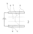
- Figure 1 shows a schematic cross section of an embodiment of an electrode, being a first or a second electrode.
- the electrode 11 has a sheet like shape with a rectangular form, but other shapes, such as a round, polygonal or hexagonal shape are also possible.
- a hole 12 is provided, which may have a rectangular shape but also other shapes, such as a round shape, are possible.
- water may be flowing along the electrode from the outer edges towards the hole, as is indicated by the dotted arrows 13 in figure 1 .
- the outer dimensions of the electrode 11 are about 16 x 16 cm and the dimensions of the hole 12 are about 3 x 3 cm.
- An advantage of a rectangular or a hexagonal shape of the electrode may be that these electrodes are efficiently produced with respect to use of material.
- An advantage of a round shaped electrode with a round hole in the centre may be that distance between the outer edge and the inner edge (i.e. the distance the water will flow along the electrode) is constant for all flow directions.
- Figure 2 shows a stack of electrodes.
- the first electrodes 21 and the second electrodes 22 each comprises a current collector, indicated by 34 in figure 3 , and an ion storage material, indicated by 35 in figure 3 .
- the current collector is connected to a power controller PC for applying an electrical potential difference between two adjacent electrodes.
- the ion storage material may store ions that have been removed from the water.
- the ion storage material may be a so-called high surface area material, with more than 500 m 2 /gr, or preferably more than 1000 m 2 /gr, or even more preferably more than 2000 m 2 /gr.
- the material may comprise activated carbon, carbon aerogels, grapheme, carbon nanofibres and/or carbon nanotubes on both sides of the electrode which are in contact with the water.
- FIG. 3 shows a schematic representation of an apparatus for removal of ions for use with the invention.
- the apparatus has a housing 31, provided with a water inlet 32 and a water outlet 33.
- the water will flow from the inlet 31 to the outlet 33 through the flow through capacitor (FTC), comprising a pair of a first electrode 21 and an adjacent second electrode 22.
- FTC flow through capacitor
- the spacer 36 may have a shape as is depicted in figure 1 .
- the main function of a spacer is to separate the first electrode from the second electrode, for example by maintaining a constant or fixed distance between the two electrodes.
- a power controller PC By applying an electrical potential difference between the first and second electrode by a power controller PC, for example by applying a positive voltage to the first electrodes (the anodes) 21 relative to the second electrodes 22, which are the cathodes, the anions of the water flowing through the spacer 36 are attracted to the first electrodes 21 and the cations are attracted to the second electrodes 22. In this way the ions (anions and cations) will be removed from the water flowing through the spacer 36.
- the electrodes may be provided with a charge barrier, for example an ion exchange membrane or an ion selective membrane.
- a charge barrier for example an ion exchange membrane or an ion selective membrane.
- the membrane provided on the cathode may be permeable for cations and only substantially allow the transport of cations and substantially block the transport of anions and the membrane provided on the anode may be permeable for anions and substantially block the transport of cations.
- the electrical potential differences between the anode and the cathode are rather low, for example lower than 2 Volt, preferably lower than 1,7 Volt and even more preferably lower than 1,4 Volt.
- a power controller is used to control the conversion of the voltage and electrical current from a power supply to the required voltage difference over the first and second electrode.
- An element of the efficiency of the apparatus is the ion flux, whereby the ion flux may then be defined as the number of ions removed from the water, for example from the water in a spacer to one of the electrodes per unit time per projected electrode area.
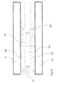
- Figure 4 shows two adjacent electrodes in an apparatus for removal of ions.
- the dotted line 41 indicates the concentration of ions in the water flowing between the two electrodes.
- the ion concentration is lower than in the centre.
- the ion concentration in the water in region 42 may be lower than the ion concentration in region 43.
- the ion concentration may decrease gradually or even linearly with the distance from one of the electrodes and that therefore the choice of regions is arbitrary.
- ion exchange membranes or ion selective membranes which are placed between the electrode and the spacer, then a similar situation may occur, whereby the ion concentration in the water in region 42 may be lower than the ion concentration in region 43.
- a low ion concentration close to the electrode (or membrane) may result in a low ion flux to the electrode (or through the membrane) to the electrode.
- the ion flux may be increased, hence improving the ion removal efficiency.
- the ion concentration near the electrodes may be increased for example by mixing the water, by the displacement of the water in a direction perpendicular to electrodes or by increasing the mobility of the ions in the water.
- the ion improvement device comprises a mixing device.
- the mixing device may be a spacer with a special structure that causes mixing of the water and which may even cause turbulence in the water.
- the spacer may have a spiral or a helical structure.
- Helical spacers may influence the water flow by forcing the fluid to twist along the spacer. The effect may be a faster local velocity of the water or it may results in that water with higher ion concentration further away from the electrode (or membrane) is brought closer to the electrode (or membrane), which may increase the ion flux towards the electrode.
- a helical spacer may improve the ion flux by a factor up to two times compared to non-helical spacers.
- helical spacers may increase the mixing of the water where the flow is still laminar.
- Helical spacers may also promote turbulence in the flow channel, which may further improve the mixing of the water.
- the mixing device causes a unsteady flow in the water.
- the flow profile is not constant, i.e. it changes over time.
- the flow velocity at a certain point may change over time and/or its direction.
- the ion flux improvement device may also comprise a turbulence creator to create a turbulent flow in the water in the spacer or a recirculation circuit with a pump and a storage facility.
- a turbulence creator to create a turbulent flow in the water in the spacer or a recirculation circuit with a pump and a storage facility.
- water from the FTC with low ion concentration may be mixed with water in the storage facility with a higher ion concentration.
- the storage water may be used for other purposes, for example as a swimming pool, or for irrigation.
- the ion flux improvement device comprises a spacer, which is ion-conductive or comprises ion-conductive material.
- Ion-conductive spacers may improve the ion mobility towards one of the electrodes.
- Ion-conductive spacers may comprise a membrane (for example: anion exchange membrane, cation exchange membrane, mosaic membranes (for mixed charges) and bipolar membranes) or ion exchange resins (for example anion exchange resin, cation exchange resin and mixed ion exchange resin).
- Ion-conductive spacers allow the passage of charged species such as ions and may increase the mobility of the ions towards one of the electrodes.
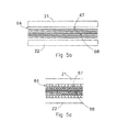
- Figure 5a shows a schematic cross section of a first and a second electrode, between which water is flowing.
- the elements in figure 5 such as electrodes 21 and 22 and their sizes and mutual distances are depicted schematically. It may be that the flow of water through the spacer is more or less laminar, e.g. the water flows in more or less constant layers (parallel to the electrodes) without mixing of the water or without water flowing with a direction component perpendicular to the electrodes.
- region 61 the flow velocity of a laminar flow parallel to the electrodes is depicted, wherein the length of the straight arrows indicates the velocity of the flow: a longer arrow indicates a higher velocity.
- the ion improvement device may comprise a velocity adjuster 64 for adjusting a flow velocity of a first portion of the water with respect to a second portion of the water, wherein, in use i.e. during ion removal from the water, in said first portion an ion concentration is higher than in said second portion. If a portion of water experiences the electrical potential difference longer (i.e. its flow velocity is lower) than another portion of water, then at the same ion concentration in the water the number of ions removed from this portion will be higher than from another portion of water that experiences the electrical potential difference shorter in time.
- Velocity adjuster 64 may be located in the spacer, along the spacer, or outside the spacer or it may be incorporated in the spacer. Without the velocity adjuster 64 the flow in the flow channel will follow a parabolic ("Poisseuille") profile with a maximum flow velocity in the centre of the flow channel and zero flow at both electrode surfaces.
- the velocity adjuster 64 is constructed to change the velocity of the water in such way, that a portion of the water flowing further away from one of the electrodes (for example in region 63) is flowing slower relative to a portion flowing closer to one of the electrodes (for example in region 62).
- Region 65 depicts a possible effect on the flow velocity of the water, wherein the length of the straight arrows indicates the absolute velocity of the flow: a longer arrow indicates a higher velocity and the orientation of the arrow indicates the direction of the flow.
- the velocity adjuster 64 has reduced the velocity of the water so much that the velocity in the centre of the flow channel has become lower than closer to the electrodes. Nevertheless, in another embodiment the velocity adjuster 64 a lower reduction of the flow velocity in the centre may be achieved, whereby the flow will only gradually decrease from the centre to close to the electrodes. In another embodiment the velocity adjuster may cause the velocity to be more uniform inside the spacer, whereby the flow velocity will be substantially independent from the distance from the electrode..
- the velocity adjuster 64 may comprise a porous material, wherein the flow resistance in the centre of the velocity adjuster is larger than in the edges, causing the velocity of the water passing through the centre of the velocity adjuster 64 (for example in region 63) to be reduced compared to the water passing through the edges of the velocity adjuster 64 (for example in region 62).
- the flow resistance of this velocity adjuster may be continuously increasing from the edge, near one of the electrodes, towards the centre of the velocity adjuster, i.e. the central axis of the spacer.
- the porosity of the velocity adjuster 64 may be varied from a value larger than 70%, preferably larger than 80%, and most preferably larger than 90% close to the electrodes (e.g.
- Porosity may be measured as a percentage of the volume of voids over the total volume.
- the velocity adjuster 64 for use in the apparatus for removing ions may comprise a spacer with multiple layers between the electrodes and the layers close to the electrodes may have a low flow resistance and the layers further away from the electrodes a relatively higher flow resistance.
- the low flow resistance may cause a higher velocity of the water close to the electrodes and the higher flow resistance may cause a lower velocity of the water further away from the electrodes.
- Without the velocity adjuster 64 less ions will be removed from the water in the centre of the flow channel or spacer, because these ions will have to migrate over a larger distance whereas the residence time of the ion in the centre of the flow channel or spacer is lower than that closer to the electrodes.
- the layers in the spacers may be provided with a porous material with a low flow resistance in a first direction and a higher flow resistance in a second direction. This may be achieved by orientating fibers in the spacer substantially parallel to the first direction and/or perpendicular to the second direction.
- the layers in the spacer close to the electrodes may be orientated such that the first direction is substantially equal to the water flow direction.
- the water may therefore experience a low flow resistance close to the electrodes and the speed of the water may therefore be relatively high.
- the layers in the spacer further away from the electrodes are orientated such that the second direction is substantially equal to the water flow direction so that the water further away from the electrodes experience a higher resistivity resulting in a lower velocity of the water.
- the thickness of the spacer with the velocity adjuster may be 20-300 micrometer, preferably 40-200 micrometer, more preferably 60-150 micrometer and most preferably 70-120 micrometer.
- a velocity adjuster comprises a material that closes off the spacer but has several small channels in the longitudinal direction of the spacer through which water may pass from one side to the other.
- the overal cross section of the channels in the region near the edges may be larger than the overal cross section of the channels in the central region of the velocity adjuster 64.
- FIG. 5b is an example of such a velocity adjuster 64 for use in the apparatus for removing ions according to an embodiment of the invention.
- the velocity adjuster 64 is provided with channel walls 66 creating small channels 67, 68 in the spacer 64.
- the channel walls 66 are permeable for water and/or ions flowing through them but they create a resistivity for the water flow. As depicted the channel walls are parallel to the electrodes but they may also be more randomly oriented.
- the small channels 68 in the middle of the spacer create a higher flow resistivity then the larger small channels 67 closer to the electrodes.
- the flow velocity of the water flowing in the flow direction 69 is thereby adjusted so that the flow velocity is lower in the middle of the spacer than the flow velocity closer to the electrodes 21, 22.
- the flow resistance of the small channels may be continuously increasing from the larger small channels 67 near the edge, near one of the electrodes 21, 22, towards the middle, i.e. the central small channel 68 of the spacer.
- the water further away of the electrodes may get a lower velocity so that it stays longer between the electrodes and there is more time by the electrodes 21, 22 to attract the ions.
- Water close to the electrodes may relatively fast be de-ionized because of the close proximity of the electrodes and may therefore be a relatively short time between the electrodes.
- the water further away from the electrodes may because of the higher flow resistance further away from the electrodes also be moved towards the electrodes so that the ions are more easily attracted to the electrodes.
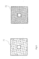
- Figure 5c discloses a cross section of the velocity adjuster 64 of figure 5b perpendicular to the flow direction 69.
- Figure 5c discloses that the small channels have a total cross section which is decreasing close to the centre 68 of the flow channel and which is increasing closer 67 to the electrodes 21, 22.
- FIG. 6 Another example of a velocity adjuster may be a shifted spacer, as is depicted in figure 6 .
- the spacer may comprise a grid structure 71.
- the grid structure will influence the velocity of the water flowing through the spacer. It may also cause mixing of the water or cause a displacement of the water in a direction perpendicular to electrodes. By shifting or rotating the orientation of the grid with respect to the electrode, these effects may be further optimized.
- Figure 6 shows a shifted grid structure 72.
- the shift or rotation of the orientation may be around 45 degrees, where the threads of the spacer are at an angle of around 45 degrees with respect to the side of one of the electrodes, as can be seen from figure 6 . Or in other words, the threads of the spacer are parallel to the diagonal of the electrode.
- the dimensions of the spacer are about the same as the dimension of the electrode shown in figure 1 or maybe a bit larger, for example 17x17 cm.
- Figure 7 shows another embodiment of the ion flux improvement device, comprising an electrical current measurement device A and a flow controller FC.
- the current measurement device A measures the current flowing to the first electrode 21 or to the second electrode 22.
- the ion flux is a function of the electrical current and the electrical current may thus be used as a measure for the ion flux.
- the current measurement device A provides a current signal to the flow controller FC, which may adjust the water flow depending on the measured electrical current.
- the flow controller FC may be arranged for adjusting the flow velocity of the water, for example by controlling the pump P, via a control signal. In this way, the ion flux may be controlled via the flow controller.
- the ion flux may increase to one of the electrodes (or to the ion exchange membrane or ion selective membrane), because of an increased ion concentrations nearby, for example in region 42 in figure 4 .
- An optimum ion flux to the electrode (or membrane) may be obtained when the percentage of ions removed from the water per cycle is relatively low, for example below 80%, preferably below 60% more preferably below 40% or even more preferably below 20%. In one cycle the water flows once between two FTC electrodes.
- High ion fluxes may thus be obtained for example at flow velocities higher than 1 liter/m 2 projected electrode area/min, or higher than 2 liter/m 2 projected electrode area/min or even higher than 3 liter/m 2 projected electrode area/min up to even higher than 4 liter/m 2 projected electrode area/min.
- the ion flux which is defined per unit time per projected electrode area, may increase because the number of cycles per unit time may also increases with higher flow velocities.
- the ion flux improvement devices may comprise a deionization rate measurement device to measure the deionization rate (i.e. the percentage of ions removed from the water) per cycle.
- the deionization rate measurement device may comprise two ion concentration measurement devices, one measuring the ion concentration of the water before the water flows between the two electrodes and one measuring the ion concentration of the water after flowing between the two electrodes.
- the deionization rate measurement device may comprise only one of these two ion concentration measurement devices and an electrical current measurement device as described above.
- the deionization rate measurement device may calculate the deionization rate on the basis of one measurement of the ion concentration and the measurement of the current flowing to one of the electrodes.
- the deionization rate measurement device may provide a deionization rate signal indicating the measured or calculated deionization rate.
- the ion flux improvement device may further comprises a flow controller to control the water flow in response to the deionization rate signal.
- a flow controller to control the water flow in response to the deionization rate signal.
- the ion flux may be higher than 0.5 gram salt per m 2 projected electrode area per min, preferably higher than 1.0 gram salt per m 2 projected electrode area per min, more preferably higher than 1.5 gram salt per m 2 projected electrode area per min or even more preferably higher than 2.0 gram salt per m 2 projected electrode area per min.
- the pressure drop may cause the flow regime to change from a laminar flow to a unsteady or turbulent flow.
- the pressure drop shows a linear relationship with the flow velocity.
- the pressure drop over the spacer or flow channel is no longer linear with the flow velocity, but increases more rapidly with the flow. This requires more pumping energy.
- the pressure drop should be limited, for example in the range of 0 - 20 bar per m 2 projected electrode area, or more preferably in the range of 15-18 bar and even more preferably in the range of 2- 10 bar per m 2 projected electrode area.
- the pressure drop may also be limited to 0.1 -20 bar preferably 1-15 bar per m 2 projected electrode area.
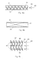
- Figure 8a discloses a cross-section of an apparatus for removal of ions according to a further embodiment of the invention comprising a first and second electrode 21, 22 and a spacer between the first and second electrode 21, 22.
- the spacer may have an helical structure 81.
- the thickness of the spacer with the helical structure 81 may be 20-300 micrometer, preferably 40-200 micrometer, more preferably 60-150 micrometer and most preferably 70-120 micrometer.
- the helical structure 81 may influence the principle water flow 83 by forcing the fluid to twist along the helical structure in a direction 85.
- the effect may be a faster local velocity of the water or it may results in that water with a higher ion concentration further away from the electrode (or membrane) may be brought closer to the electrode (or membrane), which may increase the ion flux towards the electrode.
- a helical structure in the spacer may improve the ion flux by a factor up to two times compared to spacers without helical structures.
- helical structures may increase the mixing of the water where the flow is still laminar. Helical structures may also promote turbulence in the flow channel, which may further improve the mixing of the water.
- the electrodes may be provided with a flat surface and multiple helical structures may be sandwiched between the flat surface of the first electrode and the flat surface of the second electrode.
- the spacer is to keep the surfaces of the two electrodes at a substantial constant distance of for example between 0,02 and 0,5 mm. The latter is important because if the distance between the electrodes is irregular then this may affect the flux of ions towards the electrode with lower fluxes where the spacer is thicker.
- the helical structure 81 provides seven twists over the length of the helical structure. Seven twists assures that the water is flowing along each electrode at least seven times.
- the porosity of the spacer with the helical structure may be larger than 50%, preferably larger than 60%, more preferably larger than 70% and most preferably larger than 90%.
- Figure 8b discloses a cross-section of an apparatus for removal of ions according to a further embodiment of the invention comprising a first and second electrode 21, 22 and a spacer between the first and second electrode 21, 22.
- the spacer is provided with a helical structure 81 having a less steep torsion and only half a twist in total.
- An advantage may be that the flow resistance in such case is lower and that the water will rotate along an electrode.
- An optimum between low flow resistance and sufficient interaction with the electrodes may be with a number of twists between 0,5 and 7, preferably between 1 and 5 and most preferable between 2 and 4 twists.
- Figure 8c discloses a cross-section of an apparatus for removal of ions according to a further embodiment of the invention.
- Figure 8c gives a top view of a spacer with one of the electrodes removed so that the multiple adjacent helical structures 81 on top of the flat surface of the electrode 22 can be seen.
- the helical structures are provided with four and half twists and the twists of two adjacent helical structures 81 are opposite.
- the helical structures 81 cause the water to twist 85 around the principle flow direction 83 of the water and since two adjacent helical structures 81 have an opposite twist the water in between the helical structures 81 move in the same direction perpendicular to the principle flow direction 83. This may improve the flow of the water towards the electrodes at a position 89 in between the helical structures 81. Since two adjacent helical structures are co-operating there may be a relatively low increase of the flow resistance.
- the twist direction of two adjacent helical structures 81 may also be the same which causes turbulences in between the helical structures and improved mixing.
- the helical structures in figure 8c are provided with a support 87 in the centre. This forces the water out of the centre of the helical structure towards the electrodes where the water is de-ionized.
- Any embodiment of the above described apparatus for removal of ions from water may be used for the removal of ions from water in a swimming pool, from water in a storage tank or from water in a factory plant or from ground water.
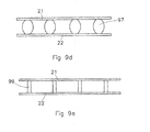
- Figure 9a discloses a cross-section of an apparatus for removal of ions according to a further embodiment of the invention comprising a first and second electrode 21, 22 and a spacer between the first and second electrode 21, 22.
- the spacer may have a structure as a pillar 91 to keep the electrodes at a fixed distance.
- the thickness of the spacer with the pillar structure may be 20-300 micrometer, preferably 40-200 micrometer, more preferably 60-150 micrometer and most preferably 70-120 micrometer.
- the pillar structure 91 may be produced in a netting structure or frame work 93 to form a layer which may form the spacer.
- the spacer is electrically insulating but at the same time open enough for water and ions to move through.
- the term pillar is to be interpreted as a structural element that keeps the first and second electrode at a distance.
- the netting 93 keeps the pillar 91 perpendicular compared to the main direction of the spacer.
- the netting frame work causes a higher flow resistivity in the middle of the flow channel between the electrodes 21, 22 thereby forcing the water in the flow channel to move closer to the first or second electrode resulting in increased deionization of water.
- the netting framework and the pillars may cause better mixing of the water in the flow channel, which may increase the ion flux towards the electrode.
- the spacer comprising pillars and a netting is that it creates a very open spacer, especially in the flow direction, with a low flow resistivity, which may result in a lower pressure drop over the channel, or increased flow in the flow channel and it may also result in a reduced risk of fouling of the spacer.
- the porosity of the spacer with the pillar structure may be larger than 50%, preferably larger than 60%, more preferably larger than 70% and most preferably larger than 90%.
- the electrodes may be provided with a flat surface and multiple pillars held by the netting may be sandwiched between the flat surface of the first electrode and the flat surface of the second electrode.
- One of the functions of the spacer is to keep the surfaces of the two electrodes at a substantial constant or fixed distance of for example between 0,02 and 0,5 mm. The latter is important because if the distance between the electrodes is irregular, then the ion flux towards the electrodes may be affected.
- Figure 9b gives a top view of a part of a spacer with one of the electrodes removed so that the multiple adjacent pillars 91 on top of the flat surface of the electrode 22 which are held in the netting 93 can be seen.
- the netting 93 provides support over the full surface of the electrode so that it keeps the pillars 91 perpendicular to the surface of the electrode as well as at a fixed distance of each other.
- Figure 9c discloses a cross-section of an apparatus for removal of ions according to a further embodiment of the invention.
- the pillar 95 in this embodiment may be provided with a spherical, elliptical or egg shape so that the pillar structure may have a thicker middle portion so as to provide for a higher flow resistivity in the middle of the flow channel in order to force the water flowing in the centre part of the flow channel between the electrodes 21, 22 in the direction of the electrodes. At the same time the flow velocity in the centre of the flow channel may be reduced compared to that of the water flowing closer to the first and/or second electrode.
- the pillar may also have a conical or rhombus structure, which is thicker in the middle than at the edges.
- the spacer is provided with a netting 97 to keep het pillars 95 in position.
- the netting of figure 9b may be constructed similar as the netting in figure 9b .
- Figure 9d discloses a cross-section of an apparatus for removal of ions according to a further embodiment of the invention.
- This embodiment is the same as the embodiment of figure 9c except that the netting is omitted.
- the pillars 97 may be spherical, elliptical, conical, rhombus or ball shaped so as to provide a higher flow resistivity further away from the electrode 21, 22 and hence increasing the residence time of the water in the centre of the channel compared to that of the edges of the spacer.
- the pillars 97 may be attached to the electrodes so that the electrodes keep the pillars perpendicular to the electrode surface by for example a glue or a specific coating.
- the pillars may also be produced by printing the pillars on the first electrodes with for example a 3D printer and subsequently providing the second electrode on top of the already printed electrodes.
- the pillars may also be printed on top of an additional layer, for example an ion exchange membrane, which may be placed on top of the electrode as a separate layer or as a coating or laminate.
- Figure 9e discloses a cross-section of an apparatus for removal of ions according to a further embodiment of the invention. This embodiment is the same as the embodiment of figure 9a and 9b except that the netting is omitted.
- the pillars 99 may be connected to the electrodes so that the electrodes keep the pillars perpendicular to the electrodes.
- the pillars may be produced by printing the pillars on the electrodes with for example a 3D printer.
- An advantage of the pillars without netting is that a very open spacer is created in which the flow resistivity is reduced as well as the risk of fouling.
- ions may be removed by providing a method comprising the steps of a) providing a first and a second electrode in a housing; b) providing an electrical potential difference between the first and the second electrode; c) allowing water to flow between the first and the second electrode from an inlet in the housing to an outlet in the housing; and d) improving the ion flux from the water to one of the first and the second electrode.
- the apparatus may be provided with a housing comprising: a water inlet for letting water in the housing; a water outlet for letting water out of the housing; a first and a second electrode connected to a power controller for applying an electrical potential difference between the first and the second electrode; the apparatus may be provided with an ion flux improvement device for improving the ion flux from the water flowing between the first and second electrode to one of the first and the second electrode.
- the ion flux improvement device may comprises a mixing device constructed and arranged for mixing the water, or an unsteady flow creator for creating an unsteady flow in the water, or a turbulence creator for creating turbulence in the water, or a spacer between the first and second electrode for allowing water to flow in between the first and second electrode, the spacer may have a spiral structure for changing a flow profile of the water.
- the mixing device may comprise a recirculation circuit constructed and arranged for the recirculation of water flowing between the first and second electrode, the recirculation circuit may preferably comprise a pump and a storage facility.
- the ion flux improvement device may comprise a spacer between the first and second electrode for allowing water to flow in between the first and second electrode; and, the spacer may comprise ion-conductive material to increase a mobility of ions towards one of the first and second electrode.
- the ion flux improvement device may comprises a spacer between the first and second electrode for allowing water to flow in between the first and second electrode, the first and second electrode and the spacer may have a substantially rectangular sheet-like shape, in which a hole may be provided; and the spacer may comprise a grid structure and an orientation of the grid structure may be rotated with respect to a straight side of the first and second electrode, with at least 30 degrees, or preferably in the range of 30-50 degrees or more preferably about 45 degrees.
- the ion flux improvement device may comprise a velocity adjuster constructed and arranged for adjusting a flow velocity of a first portion of the water with respect to a second portion of the water, wherein, in use, i.e. when removing ions from water, in said first portion an ion concentration is higher than in said second portion.
- the ion flux improvement device may comprise an electrical current measurement device arranged and constructed for measuring an electrical current between the first and the second electrode and for sending a current signal indicating said electrical current; and a flow controller arranged and constructed for receiving said current signal and for adjusting a flow velocity at which the water is flowing between the first and second electrode in response to said current signal.
- the flux improvement device may comprise a deionization rate measurement device arranged and constructed for measuring a deionization rate per cycle of the water flowing between the first and the second electrode and for sending a deionization rate signal indicating said deionization rate; and, a flow controller (FC) arranged and constructed for receiving said deionization rate signal and for adjusting a flow velocity at which the water is flowing between the first and second electrode (21, 22) in response to said deionization rate signal.
- the flow controller may be arranged and constructed to maintain the deionization rate below 60%, preferably below 40% or even more preferably below 20% of ions removed per cycle.
- the percentage of ion removal per cycle may be increased for example from 20% in the first cycle to 40% in the second cycle to 60% in the third cycle and to 80% in the fourth cycle and effectively almost complete removal in the fifth's cycle.
- the flow controller may be arranged and constructed to maintain liter/m 2 projected electrode area/min, or even more preferably higher than 4 liter/m 2 projected electrode area/min.
- the flow controller (FC) may be constructed and arranged for sending a control signal to a pump (P), the pump (P) being constructed and arranged for receiving said control signal and for pumping the water between the first and second electrode (21, 22) with a flow velocity in response to said control signal.
Landscapes
- Chemical & Material Sciences (AREA)
- Chemical Kinetics & Catalysis (AREA)
- Life Sciences & Earth Sciences (AREA)
- Electrochemistry (AREA)
- Analytical Chemistry (AREA)
- Molecular Biology (AREA)
- Health & Medical Sciences (AREA)
- General Chemical & Material Sciences (AREA)
- Hydrology & Water Resources (AREA)
- Engineering & Computer Science (AREA)
- Environmental & Geological Engineering (AREA)
- Water Supply & Treatment (AREA)
- Organic Chemistry (AREA)
- Water Treatment By Electricity Or Magnetism (AREA)
Priority Applications (1)
| Application Number | Priority Date | Filing Date | Title |
|---|---|---|---|
| EP11720101.2A EP2571817B1 (en) | 2010-05-17 | 2011-05-17 | Apparatus for removal of ions, and a method for removal of ions |
Applications Claiming Priority (3)
| Application Number | Priority Date | Filing Date | Title |
|---|---|---|---|
| EP10163021 | 2010-05-17 | ||
| EP11720101.2A EP2571817B1 (en) | 2010-05-17 | 2011-05-17 | Apparatus for removal of ions, and a method for removal of ions |
| PCT/EP2011/058001 WO2011144636A1 (en) | 2010-05-17 | 2011-05-17 | Apparatus for removal of ions, and a method for removal of ions |
Publications (2)
| Publication Number | Publication Date |
|---|---|
| EP2571817A1 EP2571817A1 (en) | 2013-03-27 |
| EP2571817B1 true EP2571817B1 (en) | 2015-01-14 |
Family
ID=42751940
Family Applications (2)
| Application Number | Title | Priority Date | Filing Date |
|---|---|---|---|
| EP11720101.2A Not-in-force EP2571817B1 (en) | 2010-05-17 | 2011-05-17 | Apparatus for removal of ions, and a method for removal of ions |
| EP11721755.4A Not-in-force EP2571606B1 (en) | 2010-05-17 | 2011-05-17 | Apparatus for removal of ions, and a method of manufacturing an apparatus for removal of ions from water |
Family Applications After (1)
| Application Number | Title | Priority Date | Filing Date |
|---|---|---|---|
| EP11721755.4A Not-in-force EP2571606B1 (en) | 2010-05-17 | 2011-05-17 | Apparatus for removal of ions, and a method of manufacturing an apparatus for removal of ions from water |
Country Status (5)
| Country | Link |
|---|---|
| US (2) | US20130081949A1 (enExample) |
| EP (2) | EP2571817B1 (enExample) |
| JP (1) | JP5783475B2 (enExample) |
| CN (1) | CN102906028B (enExample) |
| WO (3) | WO2011144635A1 (enExample) |
Cited By (1)
| Publication number | Priority date | Publication date | Assignee | Title |
|---|---|---|---|---|
| EP3995459A1 (en) | 2020-11-05 | 2022-05-11 | Voltea | Ion-selective membrane-capacitive deionization system with dynamic management of water quality |
Families Citing this family (10)
| Publication number | Priority date | Publication date | Assignee | Title |
|---|---|---|---|---|
| US20110056843A1 (en) | 2009-09-08 | 2011-03-10 | Patrick Michael Curran | Concentric layer electric double layer capacitor cylinder, system, and method of use |
| CN102906028B (zh) | 2010-05-17 | 2014-11-12 | 沃尔泰亚公司 | 去除离子的装置以及去除离子的方法 |
| KR102093443B1 (ko) * | 2012-11-29 | 2020-03-25 | 삼성전자주식회사 | 전기 흡착 탈이온 장치 및 이를 사용한 유체 처리 방법 |
| USD739349S1 (en) * | 2013-02-12 | 2015-09-22 | IDEMITSU KOGYO Co., LTD. | Current plate for insulation washer for power transformer |
| JP5678388B1 (ja) * | 2013-04-15 | 2015-03-04 | 有限会社ターナープロセス | 系に保持されている水性液体のイオン濃度を低減する装置および方法、ならびにその装置を備える装置 |
| US9859066B2 (en) | 2013-05-24 | 2018-01-02 | Atlantis Technologies | Atomic capacitor |
| KR102092941B1 (ko) | 2013-06-12 | 2020-03-24 | 삼성전자주식회사 | 전기 흡착 탈이온 장치 및 이를 사용한 유체 처리 방법 |
| US10787378B2 (en) | 2018-05-30 | 2020-09-29 | Atlantis Technologies | Spirally wound electric double layer capacitor device and associated methods |
| KR102766275B1 (ko) * | 2022-03-08 | 2025-02-13 | 한국원자력연구원 | 일정한 방향의 순흐름을 이용한 탈염 장치 및 탈염 방법 |
| CN118387991A (zh) * | 2024-04-22 | 2024-07-26 | 湖南新锋科技有限公司 | 一种电化学反应装置、电化学反应系统及电解方法 |
Citations (1)
| Publication number | Priority date | Publication date | Assignee | Title |
|---|---|---|---|---|
| WO2011138663A1 (en) * | 2010-05-05 | 2011-11-10 | Idropan Dell'orto Depuratori S.R.L. | Operating method of an apparatus for purifying a fluid and apparatus for purifying a fluid |
Family Cites Families (27)
| Publication number | Priority date | Publication date | Assignee | Title |
|---|---|---|---|---|
| BE482435A (enExample) * | 1947-06-13 | |||
| US3607735A (en) * | 1969-07-02 | 1971-09-21 | Air Reduction | System for treatment of secondary sewage |
| US4872959A (en) * | 1987-07-17 | 1989-10-10 | Cleanup & Recovery Corp. (Cure) | Electrolytic treatment of liquids |
| US5620597A (en) * | 1990-04-23 | 1997-04-15 | Andelman; Marc D. | Non-fouling flow-through capacitor |
| FR2663862B1 (fr) * | 1990-06-28 | 1993-08-13 | Le Marois Gilles | Dispositif d'electrodialyse. |
| US5503809A (en) * | 1993-04-19 | 1996-04-02 | John T. Towles | Compact ozone generator |
| DE69531415T2 (de) * | 1994-05-20 | 2004-04-15 | United States Filter Corp., Palm Desert | Kompartimente für elektrischen Entionisierungsapparat |
| US5925230A (en) * | 1997-10-06 | 1999-07-20 | Southeastern Trading, Llp | Deionization apparatus having non-sacrificial electrodes of different types |
| US6706184B2 (en) * | 2000-08-07 | 2004-03-16 | Cuno Incorporated | Unsupported multizone microporous membrane |
| JP4584485B2 (ja) * | 2001-04-10 | 2010-11-24 | 日本バイリーン株式会社 | 電気二重層キャパシタ用セパレータ及び電気二重層キャパシタ |
| CN100518910C (zh) * | 2001-04-18 | 2009-07-29 | 拜奥资源公司 | 流通电容器 |
| US6709560B2 (en) * | 2001-04-18 | 2004-03-23 | Biosource, Inc. | Charge barrier flow-through capacitor |
| US6607647B2 (en) * | 2001-04-25 | 2003-08-19 | United States Filter Corporation | Electrodeionization apparatus with expanded conductive mesh electrode and method |
| JP2004290919A (ja) * | 2003-03-28 | 2004-10-21 | Hoshizaki Electric Co Ltd | 電解槽 |
| DE10332789A1 (de) | 2003-07-18 | 2005-02-17 | Universität Stuttgart | Membrananordnung, Elektrodialysevorrichtung und Verfahren zur kontinuierlichen elektrodialytischen Entsalzung |
| US20080185294A1 (en) * | 2007-02-01 | 2008-08-07 | General Electric Company | Liquid management method and system |
| AU2007345554B2 (en) * | 2007-02-01 | 2012-07-19 | General Electric Company | Desalination method and device comprising supercapacitor electrodes |
| EP1995220B1 (en) * | 2007-05-14 | 2011-08-03 | Sanyo Electric Co., Ltd. | Water treatment device |
| KR20090093323A (ko) | 2008-02-29 | 2009-09-02 | 삼성전자주식회사 | 탈이온화 장치 및 그 제조방법 |
| DE102008031352A1 (de) * | 2008-07-02 | 2010-01-07 | Rheinisch-Westfälische Technische Hochschule Aachen | Membranvorrichtung |
| EP2253593A1 (en) | 2009-05-12 | 2010-11-24 | Voltea B.V. | Apparatus and method for removal of ions |
| EP2315342B1 (en) | 2009-10-23 | 2012-08-01 | Voltea B.V. | Apparatus for removal of ions, bi-directional power converter and method of operating an apparatus for removal of ions |
| EP2322486B1 (en) | 2009-11-04 | 2014-01-22 | Voltea B.V. | An apparatus and method for removal of ions |
| EP2383757B1 (en) * | 2010-04-29 | 2014-01-29 | Voltea B.V. | Apparatus and method for removal of ions |
| CN102906028B (zh) | 2010-05-17 | 2014-11-12 | 沃尔泰亚公司 | 去除离子的装置以及去除离子的方法 |
| NL2007599C2 (en) | 2011-10-14 | 2013-04-16 | Voltea Bv | Apparatus and method for removal removal of ions. |
| EP2692698B1 (en) | 2012-08-02 | 2015-01-14 | Voltea B.V. | A method and an apparatus to remove ions |
-
2011
- 2011-05-17 CN CN201180024162.3A patent/CN102906028B/zh not_active Expired - Fee Related
- 2011-05-17 WO PCT/EP2011/058000 patent/WO2011144635A1/en not_active Ceased
- 2011-05-17 WO PCT/EP2011/058003 patent/WO2011144638A1/en not_active Ceased
- 2011-05-17 US US13/698,265 patent/US20130081949A1/en not_active Abandoned
- 2011-05-17 EP EP11720101.2A patent/EP2571817B1/en not_active Not-in-force
- 2011-05-17 US US13/698,263 patent/US9540260B2/en not_active Expired - Fee Related
- 2011-05-17 EP EP11721755.4A patent/EP2571606B1/en not_active Not-in-force
- 2011-05-17 JP JP2013510605A patent/JP5783475B2/ja not_active Expired - Fee Related
- 2011-05-17 WO PCT/EP2011/058001 patent/WO2011144636A1/en not_active Ceased
Patent Citations (1)
| Publication number | Priority date | Publication date | Assignee | Title |
|---|---|---|---|---|
| WO2011138663A1 (en) * | 2010-05-05 | 2011-11-10 | Idropan Dell'orto Depuratori S.R.L. | Operating method of an apparatus for purifying a fluid and apparatus for purifying a fluid |
Cited By (1)
| Publication number | Priority date | Publication date | Assignee | Title |
|---|---|---|---|---|
| EP3995459A1 (en) | 2020-11-05 | 2022-05-11 | Voltea | Ion-selective membrane-capacitive deionization system with dynamic management of water quality |
Also Published As
| Publication number | Publication date |
|---|---|
| CN102906028A (zh) | 2013-01-30 |
| WO2011144635A1 (en) | 2011-11-24 |
| EP2571817A1 (en) | 2013-03-27 |
| EP2571606A1 (en) | 2013-03-27 |
| WO2011144638A1 (en) | 2011-11-24 |
| WO2011144636A1 (en) | 2011-11-24 |
| JP5783475B2 (ja) | 2015-09-24 |
| US9540260B2 (en) | 2017-01-10 |
| US20130075260A1 (en) | 2013-03-28 |
| CN102906028B (zh) | 2014-11-12 |
| EP2571606B1 (en) | 2016-10-19 |
| US20130081949A1 (en) | 2013-04-04 |
| JP2013529131A (ja) | 2013-07-18 |
Similar Documents
| Publication | Publication Date | Title |
|---|---|---|
| EP2571817B1 (en) | Apparatus for removal of ions, and a method for removal of ions | |
| CN102167463B (zh) | 水处理装置及方法 | |
| US6709560B2 (en) | Charge barrier flow-through capacitor | |
| CN101454067B (zh) | 电去离子系统中用于偏移电流分布的方法和设备 | |
| US8404093B2 (en) | Flow de-ionization using independently controlled voltages | |
| US20160023925A1 (en) | Polarized electrodialysis | |
| US9527757B2 (en) | Supercapacitor desalination cells, devices and methods | |
| JP2005539141A (ja) | 疎ら媒体の電気式脱イオン水製造装置及び方法 | |
| WO2012161663A1 (en) | A power generating device, and a method of generating power by forward osmosis | |
| US20140202880A1 (en) | Segmented electrodes for water desalination | |
| US20120145547A1 (en) | Electrical deionization apparatus | |
| US20160229717A1 (en) | Apparatus for treating a fluid | |
| US20160332897A1 (en) | Apparatus for removal of ions from water and method of producing the same | |
| EP3773998B1 (en) | Electrodialysis device for the desalination of water for oil and gas applications | |
| EP2778140B1 (en) | Apparatus for purifying a fluid and method for purifying a fluid, in particular by means of the aforesaid apparatus | |
| CN104909439A (zh) | 一种含盐废水的电吸附除盐方法 | |
| Dykstra | Desalination with porous electrodes: mechanisms of ion transport and adsorption | |
| EP2607321A1 (en) | A reverse capacitative de-ionisation apparatus and method for generating electricity | |
| KR101340450B1 (ko) | 해수의 흐름을 이용한 담수화 장치 및 담수화 방법 | |
| CN106006867B (zh) | 非膜电渗析电容脱盐装置 | |
| KR20100089251A (ko) | 축전 탈 이온화 장치, 이를 이용한 축전 탈 이온화 방법 및이를 이용한 담수화 장치, 폐수 처리 장치 | |
| KR102184220B1 (ko) | 전기흡착식 수처리 셀 및 이를 포함하는 수처리 장치 | |
| KR20130121581A (ko) | 탈이온 장치 | |
| He | Flow-electrode Capacitive Deionization (FCDI) for Ion Removal of Brackish Water: Scale-up Pathways and Evaluation | |
| CN106006868B (zh) | 四电极电容脱盐装置 |
Legal Events
| Date | Code | Title | Description |
|---|---|---|---|
| PUAI | Public reference made under article 153(3) epc to a published international application that has entered the european phase |
Free format text: ORIGINAL CODE: 0009012 |
|
| 17P | Request for examination filed |
Effective date: 20121127 |
|
| AK | Designated contracting states |
Kind code of ref document: A1 Designated state(s): AL AT BE BG CH CY CZ DE DK EE ES FI FR GB GR HR HU IE IS IT LI LT LU LV MC MK MT NL NO PL PT RO RS SE SI SK SM TR |
|
| DAX | Request for extension of the european patent (deleted) | ||
| 17Q | First examination report despatched |
Effective date: 20140129 |
|
| GRAP | Despatch of communication of intention to grant a patent |
Free format text: ORIGINAL CODE: EPIDOSNIGR1 |
|
| INTG | Intention to grant announced |
Effective date: 20141006 |
|
| GRAS | Grant fee paid |
Free format text: ORIGINAL CODE: EPIDOSNIGR3 |
|
| GRAA | (expected) grant |
Free format text: ORIGINAL CODE: 0009210 |
|
| AK | Designated contracting states |
Kind code of ref document: B1 Designated state(s): AL AT BE BG CH CY CZ DE DK EE ES FI FR GB GR HR HU IE IS IT LI LT LU LV MC MK MT NL NO PL PT RO RS SE SI SK SM TR |
|
| REG | Reference to a national code |
Ref country code: GB Ref legal event code: FG4D |
|
| REG | Reference to a national code |
Ref country code: CH Ref legal event code: EP |
|
| REG | Reference to a national code |
Ref country code: IE Ref legal event code: FG4D |
|
| REG | Reference to a national code |
Ref country code: AT Ref legal event code: REF Ref document number: 706942 Country of ref document: AT Kind code of ref document: T Effective date: 20150215 |
|
| REG | Reference to a national code |
Ref country code: DE Ref legal event code: R096 Ref document number: 602011013139 Country of ref document: DE Effective date: 20150226 |
|
| REG | Reference to a national code |
Ref country code: NL Ref legal event code: T3 |
|
| REG | Reference to a national code |
Ref country code: AT Ref legal event code: MK05 Ref document number: 706942 Country of ref document: AT Kind code of ref document: T Effective date: 20150114 |
|
| REG | Reference to a national code |
Ref country code: LT Ref legal event code: MG4D |
|
| PG25 | Lapsed in a contracting state [announced via postgrant information from national office to epo] |
Ref country code: SE Free format text: LAPSE BECAUSE OF FAILURE TO SUBMIT A TRANSLATION OF THE DESCRIPTION OR TO PAY THE FEE WITHIN THE PRESCRIBED TIME-LIMIT Effective date: 20150114 Ref country code: LT Free format text: LAPSE BECAUSE OF FAILURE TO SUBMIT A TRANSLATION OF THE DESCRIPTION OR TO PAY THE FEE WITHIN THE PRESCRIBED TIME-LIMIT Effective date: 20150114 Ref country code: NO Free format text: LAPSE BECAUSE OF FAILURE TO SUBMIT A TRANSLATION OF THE DESCRIPTION OR TO PAY THE FEE WITHIN THE PRESCRIBED TIME-LIMIT Effective date: 20150414 Ref country code: BG Free format text: LAPSE BECAUSE OF FAILURE TO SUBMIT A TRANSLATION OF THE DESCRIPTION OR TO PAY THE FEE WITHIN THE PRESCRIBED TIME-LIMIT Effective date: 20150414 Ref country code: ES Free format text: LAPSE BECAUSE OF FAILURE TO SUBMIT A TRANSLATION OF THE DESCRIPTION OR TO PAY THE FEE WITHIN THE PRESCRIBED TIME-LIMIT Effective date: 20150114 Ref country code: HR Free format text: LAPSE BECAUSE OF FAILURE TO SUBMIT A TRANSLATION OF THE DESCRIPTION OR TO PAY THE FEE WITHIN THE PRESCRIBED TIME-LIMIT Effective date: 20150114 Ref country code: FI Free format text: LAPSE BECAUSE OF FAILURE TO SUBMIT A TRANSLATION OF THE DESCRIPTION OR TO PAY THE FEE WITHIN THE PRESCRIBED TIME-LIMIT Effective date: 20150114 |
|
| PG25 | Lapsed in a contracting state [announced via postgrant information from national office to epo] |
Ref country code: IS Free format text: LAPSE BECAUSE OF FAILURE TO SUBMIT A TRANSLATION OF THE DESCRIPTION OR TO PAY THE FEE WITHIN THE PRESCRIBED TIME-LIMIT Effective date: 20150514 Ref country code: AT Free format text: LAPSE BECAUSE OF FAILURE TO SUBMIT A TRANSLATION OF THE DESCRIPTION OR TO PAY THE FEE WITHIN THE PRESCRIBED TIME-LIMIT Effective date: 20150114 Ref country code: PL Free format text: LAPSE BECAUSE OF FAILURE TO SUBMIT A TRANSLATION OF THE DESCRIPTION OR TO PAY THE FEE WITHIN THE PRESCRIBED TIME-LIMIT Effective date: 20150114 Ref country code: GR Free format text: LAPSE BECAUSE OF FAILURE TO SUBMIT A TRANSLATION OF THE DESCRIPTION OR TO PAY THE FEE WITHIN THE PRESCRIBED TIME-LIMIT Effective date: 20150415 Ref country code: RS Free format text: LAPSE BECAUSE OF FAILURE TO SUBMIT A TRANSLATION OF THE DESCRIPTION OR TO PAY THE FEE WITHIN THE PRESCRIBED TIME-LIMIT Effective date: 20150114 Ref country code: LV Free format text: LAPSE BECAUSE OF FAILURE TO SUBMIT A TRANSLATION OF THE DESCRIPTION OR TO PAY THE FEE WITHIN THE PRESCRIBED TIME-LIMIT Effective date: 20150114 |
|
| REG | Reference to a national code |
Ref country code: DE Ref legal event code: R097 Ref document number: 602011013139 Country of ref document: DE |
|
| PG25 | Lapsed in a contracting state [announced via postgrant information from national office to epo] |
Ref country code: EE Free format text: LAPSE BECAUSE OF FAILURE TO SUBMIT A TRANSLATION OF THE DESCRIPTION OR TO PAY THE FEE WITHIN THE PRESCRIBED TIME-LIMIT Effective date: 20150114 Ref country code: DK Free format text: LAPSE BECAUSE OF FAILURE TO SUBMIT A TRANSLATION OF THE DESCRIPTION OR TO PAY THE FEE WITHIN THE PRESCRIBED TIME-LIMIT Effective date: 20150114 Ref country code: SK Free format text: LAPSE BECAUSE OF FAILURE TO SUBMIT A TRANSLATION OF THE DESCRIPTION OR TO PAY THE FEE WITHIN THE PRESCRIBED TIME-LIMIT Effective date: 20150114 Ref country code: RO Free format text: LAPSE BECAUSE OF FAILURE TO SUBMIT A TRANSLATION OF THE DESCRIPTION OR TO PAY THE FEE WITHIN THE PRESCRIBED TIME-LIMIT Effective date: 20150114 Ref country code: CZ Free format text: LAPSE BECAUSE OF FAILURE TO SUBMIT A TRANSLATION OF THE DESCRIPTION OR TO PAY THE FEE WITHIN THE PRESCRIBED TIME-LIMIT Effective date: 20150114 |
|
| PLBE | No opposition filed within time limit |
Free format text: ORIGINAL CODE: 0009261 |
|
| STAA | Information on the status of an ep patent application or granted ep patent |
Free format text: STATUS: NO OPPOSITION FILED WITHIN TIME LIMIT |
|
| 26N | No opposition filed |
Effective date: 20151015 |
|
| PG25 | Lapsed in a contracting state [announced via postgrant information from national office to epo] |
Ref country code: IT Free format text: LAPSE BECAUSE OF FAILURE TO SUBMIT A TRANSLATION OF THE DESCRIPTION OR TO PAY THE FEE WITHIN THE PRESCRIBED TIME-LIMIT Effective date: 20150114 |
|
| REG | Reference to a national code |
Ref country code: CH Ref legal event code: PL |
|
| PG25 | Lapsed in a contracting state [announced via postgrant information from national office to epo] |
Ref country code: LI Free format text: LAPSE BECAUSE OF NON-PAYMENT OF DUE FEES Effective date: 20150531 Ref country code: CH Free format text: LAPSE BECAUSE OF NON-PAYMENT OF DUE FEES Effective date: 20150531 Ref country code: MC Free format text: LAPSE BECAUSE OF FAILURE TO SUBMIT A TRANSLATION OF THE DESCRIPTION OR TO PAY THE FEE WITHIN THE PRESCRIBED TIME-LIMIT Effective date: 20150114 Ref country code: LU Free format text: LAPSE BECAUSE OF FAILURE TO SUBMIT A TRANSLATION OF THE DESCRIPTION OR TO PAY THE FEE WITHIN THE PRESCRIBED TIME-LIMIT Effective date: 20150517 |
|
| REG | Reference to a national code |
Ref country code: IE Ref legal event code: MM4A |
|
| PG25 | Lapsed in a contracting state [announced via postgrant information from national office to epo] |
Ref country code: SI Free format text: LAPSE BECAUSE OF FAILURE TO SUBMIT A TRANSLATION OF THE DESCRIPTION OR TO PAY THE FEE WITHIN THE PRESCRIBED TIME-LIMIT Effective date: 20150114 |
|
| PG25 | Lapsed in a contracting state [announced via postgrant information from national office to epo] |
Ref country code: IE Free format text: LAPSE BECAUSE OF NON-PAYMENT OF DUE FEES Effective date: 20150517 |
|
| PG25 | Lapsed in a contracting state [announced via postgrant information from national office to epo] |
Ref country code: BE Free format text: LAPSE BECAUSE OF FAILURE TO SUBMIT A TRANSLATION OF THE DESCRIPTION OR TO PAY THE FEE WITHIN THE PRESCRIBED TIME-LIMIT Effective date: 20150114 |
|
| REG | Reference to a national code |
Ref country code: FR Ref legal event code: PLFP Year of fee payment: 6 |
|
| PG25 | Lapsed in a contracting state [announced via postgrant information from national office to epo] |
Ref country code: MT Free format text: LAPSE BECAUSE OF FAILURE TO SUBMIT A TRANSLATION OF THE DESCRIPTION OR TO PAY THE FEE WITHIN THE PRESCRIBED TIME-LIMIT Effective date: 20150114 |
|
| REG | Reference to a national code |
Ref country code: FR Ref legal event code: PLFP Year of fee payment: 7 |
|
| PG25 | Lapsed in a contracting state [announced via postgrant information from national office to epo] |
Ref country code: HU Free format text: LAPSE BECAUSE OF FAILURE TO SUBMIT A TRANSLATION OF THE DESCRIPTION OR TO PAY THE FEE WITHIN THE PRESCRIBED TIME-LIMIT; INVALID AB INITIO Effective date: 20110517 Ref country code: SM Free format text: LAPSE BECAUSE OF FAILURE TO SUBMIT A TRANSLATION OF THE DESCRIPTION OR TO PAY THE FEE WITHIN THE PRESCRIBED TIME-LIMIT Effective date: 20150114 |
|
| PG25 | Lapsed in a contracting state [announced via postgrant information from national office to epo] |
Ref country code: CY Free format text: LAPSE BECAUSE OF FAILURE TO SUBMIT A TRANSLATION OF THE DESCRIPTION OR TO PAY THE FEE WITHIN THE PRESCRIBED TIME-LIMIT Effective date: 20150114 |
|
| PG25 | Lapsed in a contracting state [announced via postgrant information from national office to epo] |
Ref country code: TR Free format text: LAPSE BECAUSE OF FAILURE TO SUBMIT A TRANSLATION OF THE DESCRIPTION OR TO PAY THE FEE WITHIN THE PRESCRIBED TIME-LIMIT Effective date: 20150114 |
|
| REG | Reference to a national code |
Ref country code: FR Ref legal event code: PLFP Year of fee payment: 8 |
|
| PG25 | Lapsed in a contracting state [announced via postgrant information from national office to epo] |
Ref country code: PT Free format text: LAPSE BECAUSE OF FAILURE TO SUBMIT A TRANSLATION OF THE DESCRIPTION OR TO PAY THE FEE WITHIN THE PRESCRIBED TIME-LIMIT Effective date: 20150114 Ref country code: MK Free format text: LAPSE BECAUSE OF FAILURE TO SUBMIT A TRANSLATION OF THE DESCRIPTION OR TO PAY THE FEE WITHIN THE PRESCRIBED TIME-LIMIT Effective date: 20150114 |
|
| PG25 | Lapsed in a contracting state [announced via postgrant information from national office to epo] |
Ref country code: AL Free format text: LAPSE BECAUSE OF FAILURE TO SUBMIT A TRANSLATION OF THE DESCRIPTION OR TO PAY THE FEE WITHIN THE PRESCRIBED TIME-LIMIT Effective date: 20150114 |
|
| REG | Reference to a national code |
Ref country code: NL Ref legal event code: RC Free format text: DETAILS LICENCE OR PLEDGE: RIGHT OF PLEDGE, ESTABLISHED Name of requester: BOOTSTRAP EUROPE 2.0 SARL Effective date: 20190226 |
|
| REG | Reference to a national code |
Ref country code: DE Ref legal event code: R082 Ref document number: 602011013139 Country of ref document: DE Representative=s name: KRAUS & WEISERT PATENTANWAELTE PARTGMBB, DE Ref country code: DE Ref legal event code: R081 Ref document number: 602011013139 Country of ref document: DE Owner name: VOLTEA LTD., GB Free format text: FORMER OWNER: VOLTEA B.V., SASSENHEIM, NL |
|
| REG | Reference to a national code |
Ref country code: GB Ref legal event code: 732E Free format text: REGISTERED BETWEEN 20200723 AND 20200729 |
|
| REG | Reference to a national code |
Ref country code: NL Ref legal event code: PD Owner name: VOLTEA LIMITED; GB Free format text: DETAILS ASSIGNMENT: CHANGE OF OWNER(S), ASSIGNMENT; FORMER OWNER NAME: VOLTEA B.V. Effective date: 20201119 Ref country code: NL Ref legal event code: RC Free format text: DETAILS LICENCE OR PLEDGE: RIGHT OF PLEDGE, ESTABLISHED Name of requester: BOOTSTRAP EUROPE 2.0 SARL Effective date: 20201119 Ref country code: NL Ref legal event code: RF Free format text: RIGHT OF PLEDGE, REMOVED Effective date: 20201119 |
|
| PGFP | Annual fee paid to national office [announced via postgrant information from national office to epo] |
Ref country code: NL Payment date: 20230523 Year of fee payment: 13 Ref country code: FR Payment date: 20230525 Year of fee payment: 13 Ref country code: DE Payment date: 20230519 Year of fee payment: 13 |
|
| PGFP | Annual fee paid to national office [announced via postgrant information from national office to epo] |
Ref country code: GB Payment date: 20230525 Year of fee payment: 13 |
|
| REG | Reference to a national code |
Ref country code: DE Ref legal event code: R119 Ref document number: 602011013139 Country of ref document: DE |
|
| REG | Reference to a national code |
Ref country code: NL Ref legal event code: MM Effective date: 20240601 |
|
| GBPC | Gb: european patent ceased through non-payment of renewal fee |
Effective date: 20240517 |
|
| PG25 | Lapsed in a contracting state [announced via postgrant information from national office to epo] |
Ref country code: NL Free format text: LAPSE BECAUSE OF NON-PAYMENT OF DUE FEES Effective date: 20240601 |
|
| PG25 | Lapsed in a contracting state [announced via postgrant information from national office to epo] |
Ref country code: DE Free format text: LAPSE BECAUSE OF NON-PAYMENT OF DUE FEES Effective date: 20241203 |
|
| PG25 | Lapsed in a contracting state [announced via postgrant information from national office to epo] |
Ref country code: FR Free format text: LAPSE BECAUSE OF NON-PAYMENT OF DUE FEES Effective date: 20240531 |
|
| PG25 | Lapsed in a contracting state [announced via postgrant information from national office to epo] |
Ref country code: GB Free format text: LAPSE BECAUSE OF NON-PAYMENT OF DUE FEES Effective date: 20240517 |