EP2570720B1 - Circuit board assembly and lighting device - Google Patents
Circuit board assembly and lighting device Download PDFInfo
- Publication number
- EP2570720B1 EP2570720B1 EP11863822.0A EP11863822A EP2570720B1 EP 2570720 B1 EP2570720 B1 EP 2570720B1 EP 11863822 A EP11863822 A EP 11863822A EP 2570720 B1 EP2570720 B1 EP 2570720B1
- Authority
- EP
- European Patent Office
- Prior art keywords
- printed circuit
- flexible printed
- light
- circuit board
- top surface
- Prior art date
- Legal status (The legal status is an assumption and is not a legal conclusion. Google has not performed a legal analysis and makes no representation as to the accuracy of the status listed.)
- Active
Links
Images








Classifications
-
- F—MECHANICAL ENGINEERING; LIGHTING; HEATING; WEAPONS; BLASTING
- F21—LIGHTING
- F21L—LIGHTING DEVICES OR SYSTEMS THEREOF, BEING PORTABLE OR SPECIALLY ADAPTED FOR TRANSPORTATION
- F21L4/00—Electric lighting devices with self-contained electric batteries or cells
- F21L4/02—Electric lighting devices with self-contained electric batteries or cells characterised by the provision of two or more light sources
-
- H—ELECTRICITY
- H05—ELECTRIC TECHNIQUES NOT OTHERWISE PROVIDED FOR
- H05K—PRINTED CIRCUITS; CASINGS OR CONSTRUCTIONAL DETAILS OF ELECTRIC APPARATUS; MANUFACTURE OF ASSEMBLAGES OF ELECTRICAL COMPONENTS
- H05K1/00—Printed circuits
- H05K1/02—Details
- H05K1/14—Structural association of two or more printed circuits
- H05K1/147—Structural association of two or more printed circuits at least one of the printed circuits being bent or folded, e.g. by using a flexible printed circuit
-
- F—MECHANICAL ENGINEERING; LIGHTING; HEATING; WEAPONS; BLASTING
- F21—LIGHTING
- F21K—NON-ELECTRIC LIGHT SOURCES USING LUMINESCENCE; LIGHT SOURCES USING ELECTROCHEMILUMINESCENCE; LIGHT SOURCES USING CHARGES OF COMBUSTIBLE MATERIAL; LIGHT SOURCES USING SEMICONDUCTOR DEVICES AS LIGHT-GENERATING ELEMENTS; LIGHT SOURCES NOT OTHERWISE PROVIDED FOR
- F21K9/00—Light sources using semiconductor devices as light-generating elements, e.g. using light-emitting diodes [LED] or lasers
- F21K9/20—Light sources comprising attachment means
- F21K9/23—Retrofit light sources for lighting devices with a single fitting for each light source, e.g. for substitution of incandescent lamps with bayonet or threaded fittings
- F21K9/232—Retrofit light sources for lighting devices with a single fitting for each light source, e.g. for substitution of incandescent lamps with bayonet or threaded fittings specially adapted for generating an essentially omnidirectional light distribution, e.g. with a glass bulb
-
- F—MECHANICAL ENGINEERING; LIGHTING; HEATING; WEAPONS; BLASTING
- F21—LIGHTING
- F21V—FUNCTIONAL FEATURES OR DETAILS OF LIGHTING DEVICES OR SYSTEMS THEREOF; STRUCTURAL COMBINATIONS OF LIGHTING DEVICES WITH OTHER ARTICLES, NOT OTHERWISE PROVIDED FOR
- F21V3/00—Globes; Bowls; Cover glasses
- F21V3/04—Globes; Bowls; Cover glasses characterised by materials, surface treatments or coatings
- F21V3/06—Globes; Bowls; Cover glasses characterised by materials, surface treatments or coatings characterised by the material
- F21V3/061—Globes; Bowls; Cover glasses characterised by materials, surface treatments or coatings characterised by the material the material being glass
-
- F—MECHANICAL ENGINEERING; LIGHTING; HEATING; WEAPONS; BLASTING
- F21—LIGHTING
- F21V—FUNCTIONAL FEATURES OR DETAILS OF LIGHTING DEVICES OR SYSTEMS THEREOF; STRUCTURAL COMBINATIONS OF LIGHTING DEVICES WITH OTHER ARTICLES, NOT OTHERWISE PROVIDED FOR
- F21V3/00—Globes; Bowls; Cover glasses
- F21V3/04—Globes; Bowls; Cover glasses characterised by materials, surface treatments or coatings
- F21V3/06—Globes; Bowls; Cover glasses characterised by materials, surface treatments or coatings characterised by the material
- F21V3/062—Globes; Bowls; Cover glasses characterised by materials, surface treatments or coatings characterised by the material the material being plastics
-
- F—MECHANICAL ENGINEERING; LIGHTING; HEATING; WEAPONS; BLASTING
- F21—LIGHTING
- F21Y—INDEXING SCHEME ASSOCIATED WITH SUBCLASSES F21K, F21L, F21S and F21V, RELATING TO THE FORM OR THE KIND OF THE LIGHT SOURCES OR OF THE COLOUR OF THE LIGHT EMITTED
- F21Y2107/00—Light sources with three-dimensionally disposed light-generating elements
- F21Y2107/30—Light sources with three-dimensionally disposed light-generating elements on the outer surface of cylindrical surfaces, e.g. rod-shaped supports having a circular or a polygonal cross section
-
- F—MECHANICAL ENGINEERING; LIGHTING; HEATING; WEAPONS; BLASTING
- F21—LIGHTING
- F21Y—INDEXING SCHEME ASSOCIATED WITH SUBCLASSES F21K, F21L, F21S and F21V, RELATING TO THE FORM OR THE KIND OF THE LIGHT SOURCES OR OF THE COLOUR OF THE LIGHT EMITTED
- F21Y2107/00—Light sources with three-dimensionally disposed light-generating elements
- F21Y2107/40—Light sources with three-dimensionally disposed light-generating elements on the sides of polyhedrons, e.g. cubes or pyramids
-
- F—MECHANICAL ENGINEERING; LIGHTING; HEATING; WEAPONS; BLASTING
- F21—LIGHTING
- F21Y—INDEXING SCHEME ASSOCIATED WITH SUBCLASSES F21K, F21L, F21S and F21V, RELATING TO THE FORM OR THE KIND OF THE LIGHT SOURCES OR OF THE COLOUR OF THE LIGHT EMITTED
- F21Y2115/00—Light-generating elements of semiconductor light sources
- F21Y2115/10—Light-emitting diodes [LED]
-
- H—ELECTRICITY
- H05—ELECTRIC TECHNIQUES NOT OTHERWISE PROVIDED FOR
- H05K—PRINTED CIRCUITS; CASINGS OR CONSTRUCTIONAL DETAILS OF ELECTRIC APPARATUS; MANUFACTURE OF ASSEMBLAGES OF ELECTRICAL COMPONENTS
- H05K1/00—Printed circuits
- H05K1/02—Details
- H05K1/03—Use of materials for the substrate
- H05K1/05—Insulated conductive substrates, e.g. insulated metal substrate
- H05K1/056—Insulated conductive substrates, e.g. insulated metal substrate the metal substrate being covered by an organic insulating layer
-
- H—ELECTRICITY
- H05—ELECTRIC TECHNIQUES NOT OTHERWISE PROVIDED FOR
- H05K—PRINTED CIRCUITS; CASINGS OR CONSTRUCTIONAL DETAILS OF ELECTRIC APPARATUS; MANUFACTURE OF ASSEMBLAGES OF ELECTRICAL COMPONENTS
- H05K2201/00—Indexing scheme relating to printed circuits covered by H05K1/00
- H05K2201/01—Dielectrics
- H05K2201/0137—Materials
- H05K2201/0154—Polyimide
-
- H—ELECTRICITY
- H05—ELECTRIC TECHNIQUES NOT OTHERWISE PROVIDED FOR
- H05K—PRINTED CIRCUITS; CASINGS OR CONSTRUCTIONAL DETAILS OF ELECTRIC APPARATUS; MANUFACTURE OF ASSEMBLAGES OF ELECTRICAL COMPONENTS
- H05K2201/00—Indexing scheme relating to printed circuits covered by H05K1/00
- H05K2201/10—Details of components or other objects attached to or integrated in a printed circuit board
- H05K2201/10007—Types of components
- H05K2201/10106—Light emitting diode [LED]
Definitions
- the present invention relates to a lighting unit with a light unit main body and a board assembly which comprises a plurality of flexible printed circuit board (FPCs) to which a light-emitting diode is attached.
- FPCs flexible printed circuit board
- LEDs light-emitting diodes
- a plurality of (two or more) light-emitting diodes coupled to each other can be used.
- a plurality of light-emitting diodes with a sheet-like conductor to form a strip-like light source coupler (LED module) see, e.g., Patent Literature 1.
- Patent Document 1 International Publication No. WO 2002/089222 pamphlet
- US 6 848 819 B1 discloses a light-emitting diode arrangement having the structure of a light dome of regular shape comprising an upper surface and four obliquely placed side faces. On each of the upper surface and the side surfaces there are mounted light-emitting diodes. In the space defined by such surfaces there is provided a cooling member.
- DE 20 2010 005863 U1 discloses a spherical light-emitting diode arrangement in which plural stripes each carrying a plurality of LEDs are bent to define a half circle. The ends of such half circle shaped stripes are connected so as to form a sphere.
- DE 10 2009 009 288 A1 discloses a LED lamp having a rigid carrier bolt which receives plural LEDs, and a supporting structure received by a main body onto which a glass bulb is attached.
- a general light-emitting diode applies light with high directivity and has a narrow beam angle. Accordingly, a plurality of light-emitting diodes needs to be arranged so as to face directions different from each other in a lighting unit required to illuminate a wide range. For example, in a lighting unit which emits light equally over 360° in a circumferential direction, such as an electric bulb, a plurality of light-emitting diodes need to be scatteringly arranged in a circumferential direction and in an axial direction. Such a lighting unit thus has the disadvantages of the need for a complex manufacturing process during manufacture of the lighting unit and rising manufacturing costs of the lighting unit.
- the present invention has been made in consideration of the above-described circumstances, and has as its object to provide a lighting unit which can illuminate a wide range and whose manufacturing costs can be reduced.
- a lighting unit according to the present invention is defined by the features of claim 1.
- each flexible printed circuit board desirably includes a heat-dissipating layer which is made of copper foil having a tensile strength of 400 MPa or more and a thickness of 70 ⁇ m or more.
- a top one of the plurality of flexible printed circuit boards include a light-emitting diode attaching portion to which the light-emitting diode is attached at each of the top surface portion and the side surface portions and that the other flexible printed circuit boards each include a light-emitting diode attaching portion to which the light-emitting diode is attached at each of the side surface portions.
- the light-emitting diode attaching portions of the plurality of flexible printed circuit boards are desirably set such that irradiation areas of the light-emitting diodes overlap with each other at edges when the light-emitting diodes are attached.
- a rib is formed along a side edge of each of the side surface portions in each flexible printed circuit board.
- each flexible printed circuit board desirably includes a top surface portion having a substantially rectangular shape provided at a central portion and the respective side surface portions having a substantially rectangular shape provided so as to extend from two sides of the top surface portion in substantially perpendicular directions.
- each flexible printed circuit board desirably includes a top surface portion having a substantially rectangular shape provided at a central portion and the respective side surface portions having a substantially rectangular shape provided so as to extend from two sides of the top surface portion in directions which form obtuse angles with the top surface portion.
- each flexible printed circuit board desirably includes a top surface portion having a substantially rectangular shape provided at a central portion and the respective side surface portions having a substantially trapezoidal shape provided so as to extend from two sides of the top surface portion in directions which form obtuse angles with the top surface portion, and a gap between adjacent ones of the side surface portions is desirably closed by bringing corresponding edges of the adjacent side surface portions into contact with each other.
- a plurality of light-emitting diode attaching portions are arranged so as to face directions different from each other, and so a wide range can be illuminated with a plurality of light-emitting diodes.
- the shape of a flexible printed circuit board when developed into a plane is simple. This allows an increase in the yield rate of a material and a reduction in the manufacturing costs of the board assembly or lighting unit.
- Figures 1 to 4 show a first embodiment of the present invention.
- a light-emitting diode lamp 1 is used as an example of a lighting unit
- a lamp main body 2 is used as an example of a lighting unit main body.
- the light-emitting diode lamp 1 includes the lamp main body 2, and a socket threaded portion 2a is formed at a lower portion of the lamp main body 2.
- a board assembly 3 is disposed, and a cover 4 made of a colorless, transparent glass or synthetic resin (or plastic) is attached so as to cover the board assembly 3.
- Five light-emitting diodes 5 are attached to the board assembly 3 such that the light-emitting diodes 5 can apply light in directions different from each other and such that respective irradiation areas of the light-emitting diodes 5 overlap with each other at edges in a manner corresponding to lighting angles of the light-emitting diodes 5.
- the board assembly 3 is composed of two flexible printed circuit boards 6.
- the flexible printed circuit boards 6 have the same U-shape.
- the flexible printed circuit boards 6 each include a base 7 which is in the form of a flat plate having a substantially rectangular shape (i.e., a simple shape) when developed into a plane.
- the base 7 includes connections 8 at two ends and is bent substantially at right angles along two bend lines L1 and L2 of a middle portion to form a top surface portion 9 and two side surface portions 10. Note that the two connections 8 can be connected to a power supply portion (not shown) housed in the lamp main body 2.
- the two flexible printed circuit boards 6 are three-dimensionally assembled such that the top surface portions 9 cross each other substantially at right angles and such that one of the top surface portions 9 lies on top of the other to constitute the board assembly 3.
- the upper flexible printed circuit board 6 includes one light-emitting diode attaching portion 11 at each of respective predetermined positions of the top surface portion 9 and two side surface portions 10, and the respective light-emitting diodes 5 are mounted on the light-emitting diode attaching portions 11.
- the lower flexible printed circuit board 6 includes one light-emitting diode attaching portion 11 at each of respective predetermined positions of the two side surface portions 10, and the respective light-emitting diodes 5 are mounted on the light-emitting diode attaching portions 11.
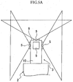
- the five light-emitting diodes 5 on the board assembly 3 apply light in the directions different from each other and have the respective irradiation areas overlapping with each other at the edges.
- any flexible printed circuit board can be used as long as the flexible printed circuit board 6 can maintain its bent shape (U-shape).
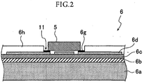
- the flexible printed circuit board 6 which are excellent at maintaining a bent shape include a flexible printed circuit board which is formed by stacking, in order, a heat-conductive adhesive layer 6b, an insulating layer 6c made of a polyimide film, and a wiring layer 6d made of copper foil having a tensile strength of 250 MPa or less and a thickness of 50 ⁇ m or less on a heat-dissipating layer 6a made of copper foil having a tensile strength of 400 MPa or more and a thickness of 70 ⁇ m or more and coating and protecting, with a resist 6h, an upper portion of the wiring layer 6d except lands 6g where the light-emitting diodes 5 are to be mounted, as shown in Figure 2 .
- the term "tensile strength” here refers to tensile strength when the flexible printed circuit board 6 is in its finished form (after the flexible printed circuit board 6 undergoes a thermal history if the flexible printed circuit board 6 is subjected to heat treatment).
- the plurality of light-emitting diodes 5 are attached to the lands 6g of the flexible printed circuit boards 6 of the board assembly 3 such that the plurality of light-emitting diodes 5 can apply light in the directions different from each other, the light-emitting diode lamp 1 can illuminate a wide range. Additionally, the plurality of light-emitting diodes 5 are attached such that the irradiation areas of the light-emitting diodes 5 overlap with each other at the edges, occurrence of blind spots can be prevented.
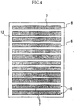
- each flexible printed circuit board 6 when developed into a plane has a simple shape, i.e., a substantially rectangular shape. If the flexible printed circuit boards 6 are laid out in a material sheet 12, as shown in Figure 4 , the number of flexible printed circuit boards 6 that can be laid out is large (as large as twelve in Figure 4 ), and the yield rate of a material is high. Additionally, as described above, the two flexible printed circuit boards 6 have the same shape (U-shape) and, even when developed into a plane, have the same shape (substantially rectangular shape). There is no need to distinguish the two flexible printed circuit boards 6. Accordingly, the manufacturing costs of the flexible printed circuit board 6 can be reduced, which in turn leads to a reduction in the manufacturing costs of the light-emitting diode lamp 1.
- a flexible printed circuit board including the heat-dissipating layer 6a made of copper foil having a thickness of 70 ⁇ m or more as the flexible printed circuit board 6 allows sufficient dissipation of heat generated by the light-emitting diodes 5.
- a flexible printed circuit board including the heat-dissipating layer 6a made of copper foil having a tensile strength of 400 MPa or more as the flexible printed circuit board 6 makes the copper foil as the heat-dissipating layer 6a unlikely to be unevenly deformed (plastically deformed), e.g., during the manufacturing process of the flexible printed circuit board 6 and allows low-cost maintenance of the flatness of the flexible printed circuit board 6. That is, even when thick copper foil is adopted as the heat-dissipating layer 6a, if the copper foil is soft, the heat-dissipating layer 6a is easily unevenly deformed to lose its flatness.
- the heat-dissipating layer 6a needs to be planarized by using a corrective jig in order to prevent a failure from occurring when the light-emitting diodes 5 are mounted.
- adoption of copper foil having a tensile strength of 400 MPa or more and high elasticity as the heat-dissipating layer 6a prevents uneven deformation of the heat-dissipating layer 6a and eliminates the need to planarize the heat-dissipating layer 6a. This allows a reduction in the manufacturing costs of the flexible printed circuit board 6.
- the heat-dissipating layer 6a can serve as a skeletal frame which maintains the U-shape. Accordingly, when a circuit element (not shown) is mounted on the flexible printed circuit board 6, an attachment position and an attachment posture of the circuit element can be stabilized.
- Figure 6 shows a second embodiment of the present invention.
- the number of flexible printed circuit boards 6 constituting a board assembly 3 is three, and top surface portions 9 of the flexible printed circuit boards 6 are made to cross each other substantially at 60°.
- a top one of the three flexible printed circuit boards 6 includes one light-emitting diode attaching portion 11 at each of respective predetermined positions of the top surface portion 9 and two side surface portions 10.
- the other two flexible printed circuit boards 6 each include one light-emitting diode attaching portion 11 at each of respective predetermined positions of the two side surface portions 10.
- the remainder of the configuration is the same as that in the first embodiment described above. Note that the same members as those in the first embodiment are denoted by the same reference numerals and that a description thereof will be omitted.
- the second embodiment achieves the same working-effects as those of the first embodiment.
- the top surface portions 9 of the three flexible printed circuit boards 6 cross each other at 60° in the second embodiment, light can be applied to surroundings more equally than in the first embodiment where the top surface portions 9 of the two flexible printed circuit boards 6 cross each other substantially at right angles.
- the amount of light can be made larger in the second embodiment than in the first embodiment by an amount corresponding to an increase in the number of light-emitting diodes 5 to be attached.
- the light-emitting 5 diodes on the board assembly 3 are arranged such that the light-emitting diodes 5 apply light in directions different from each other and such that irradiation areas of the light-emitting diodes 5 overlap with each other at edges, as in the first embodiment (see Figures 5A and 5B ).
- this configuration in the second embodiment as well, occurrence of blind spots can be prevented.
- Examples of the flexible printed circuit board 6 according to the second embodiment include a flexible printed circuit board (see Figure 2 ) which is formed by stacking, in order, a heat-conductive adhesive layer 6b, an insulating layer 6c made of a polyimide film, and a wiring layer 6d made of copper foil having a tensile strength of 250 MPa or less and a thickness of 50 ⁇ m or less on a heat-dissipating layer 6a made of copper foil having a tensile strength of 400 MPa or more and a thickness of 70 ⁇ m or more and coating and protecting, with a resist 6h, an upper portion of the wiring layer 6d except lands 6g where the light-emitting diodes 5 are to be mounted, as in the first embodiment.
- tensile strength in the second embodiment refers to tensile strength when the flexible printed circuit board 6 is in its finished form (after the flexible printed circuit board 6 undergoes a thermal history if the flexible printed circuit board 6 is subjected to heat treatment), as in the first embodiment.
- use of a flexible printed circuit board including the heat-dissipating layer 6a made of copper foil having a thickness of 70 ⁇ m or more as the flexible printed circuit board 6 allows sufficient dissipation of heat generated by the light-emitting diodes 5.
- use of the heat-dissipating layer 6a made of copper foil having a tensile strength of 400 MPa or more makes the copper foil as the heat-dissipating layer 6a unlikely to be unevenly deformed (plastically deformed), e.g., during the manufacturing process of the flexible printed circuit board 6 and allows low-cost maintenance of the flatness of the flexible printed circuit board 6.
- the board assembly 3 according to the second embodiment can also be mounted in a lighting unit 1 (see Figure 1 ) which is the same as that in the first embodiment.
- Figure 7 shows a third embodiment of the present invention.
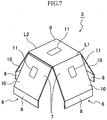
- a flexible printed circuit board 6 has a larger width, and an angle with respect to a top surface portion 9 at which side surface portions 10 are bent is an obtuse angle (e.g., about 120°).
- the remainder of the configuration is the same as that in the first embodiment described above. Note that the same members as those in the first embodiment are denoted by the same reference numerals and that a description thereof will be omitted.
- the third embodiment achieves the same working-effects as those of the first embodiment.
- the side surface portions 10 of the flexible printed circuit boards 6 are all tilted so as to face obliquely upward in the third embodiment, space above the flexible printed circuit boards 6 can be illuminated more satisfactorily than in the first embodiment.
- light-emitting diodes 5 on a board assembly 3 are arranged such that the light-emitting diodes 5 apply light in directions different from each other and such that irradiation areas of the light-emitting diodes 5 overlap with each other at edges, as in the first embodiment (see Figures 5A and 5B ).
- this configuration in the third embodiment as well, occurrence of blind spots can be prevented.
- Examples of the flexible printed circuit board 6 according to the third embodiment include a flexible printed circuit board (see Figure 2 ) which is formed by stacking, in order, a heat-conductive adhesive layer 6b, an insulating layer 6c made of a polyimide film, and a wiring layer 6d made of copper foil having a tensile strength of 250 MPa or less and a thickness of 50 ⁇ m or less on a heat-dissipating layer 6a made of copper foil having a tensile strength of 400 MPa or more and a thickness of 70 ⁇ m or more and coating and protecting, with a resist 6h, an upper portion of the wiring layer 6d except lands 6g where the light-emitting diodes 5 are to be mounted, as in the first embodiment.
- tensile strength in the third embodiment refers to tensile strength when the flexible printed circuit board 6 is in its finished form (after the flexible printed circuit board 6 undergoes a thermal history if the flexible printed circuit board 6 is subjected to heat treatment), as in the first embodiment.
- use of a flexible printed circuit board including the heat-dissipating layer 6a made of copper foil having a thickness of 70 ⁇ m or more as the flexible printed circuit board 6 allows sufficient dissipation of heat generated by the light-emitting diodes 5.
- use of the heat-dissipating layer 6a made of copper foil having a tensile strength of 400 MPa or more makes the copper foil as the heat-dissipating layer 6a unlikely to be unevenly deformed (plastically deformed), e.g., during the manufacturing process of the flexible printed circuit board 6 and allows low-cost maintenance of the flatness of the flexible printed circuit board 6.
- the board assembly 3 according to the third embodiment can also be mounted in a lighting unit 1 (see Figure 1 ) which is the same as that in the first embodiment.
- Figures 8A and 8B show a fourth embodiment of the present invention.
- the shape of a side surface portion 10 of a flexible printed circuit board 6 is substantially trapezoidal.
- the remainder of the configuration is the same as that in the third embodiment described above. Note that the same members as those in the third embodiment are denoted by the same reference numerals and that a description thereof will be omitted.
- the fourth embodiment achieves the same working-effects as those of the third embodiment.
- the width of each side surface portion 10 in each flexible printed circuit board 6 increases from a top surface portion 9 toward a connection 8 in the fourth embodiment, as shown in Figures 8A and 8B . Accordingly, heat deterioration of light-emitting diodes 5 can be inhibited by efficiently transferring heat generated by the light-emitting diodes 5 to a lamp main body 2.
- an angle with respect to the top surface portion 9 of each flexible printed circuit board 6 at which the side surface portions 10 are bent is about 120°, and corresponding edges of adjacent ones of the side surface portions 10 are in contact with each other. This configuration allows closing of gaps between the side surface portions 10 of the two flexible printed circuit boards 6. For this reason, space above the flexible printed circuit boards 6 can be further satisfactorily illuminated without letting dust enter a board assembly 3.
- the light-emitting diodes on the board assembly 3 are arranged such that the light-emitting diodes apply light in directions different from each other and such that irradiation areas of the light-emitting diodes overlap with each other at edges, as in the first embodiment (see Figures 5A and 5B ).
- this configuration in the fourth embodiment as well, occurrence of blind spots can be prevented.
- Examples of the flexible printed circuit board 6 according to the fourth embodiment include a flexible printed circuit board (see Figure 2 ) which is formed by stacking, in order, a heat-conductive adhesive layer 6b, an insulating layer 6c made of a polyimide film, and a wiring layer 6d made of copper foil having a tensile strength of 250 MPa or less and a thickness of 50 ⁇ m or less on a heat-dissipating layer 6a made of copper foil having a tensile strength of 400 MPa or more and a thickness of 70 ⁇ m or more and coating and protecting, with a resist 6h, an upper portion of the wiring layer 6d except lands 6g where the light-emitting diodes 5 are to be mounted, as in the first embodiment.
- tensile strength in the fourth embodiment refers to tensile strength when the flexible printed circuit board 6 is in its finished form (after the flexible printed circuit board 6 undergoes a thermal history if the flexible printed circuit board 6 is subjected to heat treatment), as in the first embodiment.
- use of a flexible printed circuit board including the heat-dissipating layer 6a made of copper foil having a thickness of 70 ⁇ m or more as the flexible printed circuit board 6 allows sufficient dissipation of heat generated by the light-emitting diodes 5.
- use of the heat-dissipating layer 6a made of copper foil having a tensile strength of 400 MPa or more makes the copper foil as the heat-dissipating layer 6a unlikely to be unevenly deformed (plastically deformed), e.g., during the manufacturing process of the flexible printed circuit board 6 and allows low-cost maintenance of the flatness of the flexible printed circuit board 6.
- the board assembly 3 according to the fourth embodiment can also be mounted in a lighting unit 1 (see Figure 1 ) which is the same as that in the first embodiment.
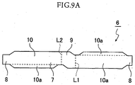
- Figures 9A to 9C show a fifth embodiment of the present invention.
- a rib 13 is formed along a side edge 10a of a side surface portion 10 of a flexible printed circuit board 6.
- the remainder of the configuration is the same as that in the first embodiment described above. Note that the same members as those in the first embodiment are denoted by the same reference numerals and that a description thereof will be omitted.
- the fifth embodiment achieves the same working-effects as those of the first embodiment.
- each side surface portion 10 of the flexible printed circuit board 6 is reinforced with the rib 13 in the fifth embodiment, the durability of the flexible printed circuit board 6 can be enhanced.
- the flexible printed circuit board 6 including the ribs 13 can be applied to any of the board assemblies 3 according to the first to fourth embodiments.
- first to fifth embodiments each have described a case where one light-emitting diode 5 is attached to each of the top surface portion 9 and side surface portions 10 of the flexible printed circuit board 6.
- the first to fifth embodiments each have described the light-emitting diode lamp 1 including the flexible printed circuit board 6 bent at two points of a middle portion of the base 7.
- the base 7 may be bent at three or more points of a middle portion as long as the top surface portion 9 and side surface portions 10 are formed in the flexible printed circuit board 6.
- first and third to fifth embodiments each have described a case where the board assembly 3 is composed of the two flexible printed circuit boards 6, and the second embodiment has described a case where the board assembly 3 is composed of the three flexible printed circuit boards 6.
- the number of flexible printed circuit boards 6 constituting the board assembly 3, however, is not limited to two or three. The number may be four or more.
- the first to fifth embodiments each have described a case where the light-emitting diode lamp 1 is adopted as a lighting unit.
- the present invention can also be applied to a lighting unit other than the light-emitting diode lamp 1.
- the present invention can be applied to a wide range of lighting units which use a light-emitting diode as a light source, such as an electric bulb, a straight luminaire (e.g., a fluorescent lamp), a ceiling light, a lantern, a plant growth light, lighting machinery in a refrigerator-freezer, a portable flashlight, a headlight of a bicycle, various types of lights of an automobile (e.g., an interior light, a side marker light, a turn-signal light, and a parking light), a guide light, an emergency light, a warning light, a dental curing light, a garden lantern, a paper lantern, and a lamp for an aquarium.
- a straight luminaire e.g., a fluorescent lamp
- a ceiling light e.g., a ceiling light, a lantern, a plant growth light, lighting machinery in a refrigerator-freezer, a portable flashlight, a headlight of a bicycle, various types of lights of an automobile (e.g., an interior light,
Landscapes
- Engineering & Computer Science (AREA)
- Microelectronics & Electronic Packaging (AREA)
- General Engineering & Computer Science (AREA)
- Physics & Mathematics (AREA)
- Optics & Photonics (AREA)
- Fastening Of Light Sources Or Lamp Holders (AREA)
- Led Device Packages (AREA)
- Arrangement Of Elements, Cooling, Sealing, Or The Like Of Lighting Devices (AREA)
- Non-Portable Lighting Devices Or Systems Thereof (AREA)
Description
- The present invention relates to a lighting unit with a light unit main body and a board assembly which comprises a plurality of flexible printed circuit board (FPCs) to which a light-emitting diode is attached.
- In recent years, light-emitting diodes (LEDs) have come into use as the light source of a lighting unit. Since a light-emitting diode has a longer life and generates less heat than an incandescent lamp and the like, a plurality of (two or more) light-emitting diodes coupled to each other can be used. As an example, there is proposed the idea of coupling a plurality of light-emitting diodes with a sheet-like conductor to form a strip-like light source coupler (LED module) (see, e.g., Patent Literature 1).
-
US 6 848 819 B1 discloses a light-emitting diode arrangement having the structure of a light dome of regular shape comprising an upper surface and four obliquely placed side faces. On each of the upper surface and the side surfaces there are mounted light-emitting diodes. In the space defined by such surfaces there is provided a cooling member. -
DE 20 2010 005863 U1 discloses a spherical light-emitting diode arrangement in which plural stripes each carrying a plurality of LEDs are bent to define a half circle. The ends of such half circle shaped stripes are connected so as to form a sphere. -
DE 10 2009 009 288 A1 discloses a LED lamp having a rigid carrier bolt which receives plural LEDs, and a supporting structure received by a main body onto which a glass bulb is attached. - A general light-emitting diode, however, applies light with high directivity and has a narrow beam angle. Accordingly, a plurality of light-emitting diodes needs to be arranged so as to face directions different from each other in a lighting unit required to illuminate a wide range. For example, in a lighting unit which emits light equally over 360° in a circumferential direction, such as an electric bulb, a plurality of light-emitting diodes need to be scatteringly arranged in a circumferential direction and in an axial direction. Such a lighting unit thus has the disadvantages of the need for a complex manufacturing process during manufacture of the lighting unit and rising manufacturing costs of the lighting unit.
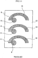
- As a way to overcome the disadvantages, for example, it is conceivable to attach light-emitting diodes (not shown) to a
top surface portion 9 and aside surface portion 10 of a frusto-conical flexible printedcircuit board 6, as shown inFigure 10 . The idea, however, complicates the shape of the flexible printedcircuit board 6 when developed into a plane. If the flexible printedcircuit boards 6 are laid out in amaterial sheet 12, as shown inFigure 11 , the number of flexible printedcircuit boards 6 that can be laid out is small (only three inFigure 11 ), and the yield from a material is low. Accordingly, the idea does not contribute much to a reduction in manufacturing costs. - The present invention has been made in consideration of the above-described circumstances, and has as its object to provide a lighting unit which can illuminate a wide range and whose manufacturing costs can be reduced.
- A lighting unit according to the present invention is defined by the features of claim 1.
- In the lighting unit according to the present invention, each flexible printed circuit board desirably includes a heat-dissipating layer which is made of copper foil having a tensile strength of 400 MPa or more and a thickness of 70 µm or more.
- In the lighting unit according to the present invention, it is desirable that a top one of the plurality of flexible printed circuit boards include a light-emitting diode attaching portion to which the light-emitting diode is attached at each of the top surface portion and the side surface portions and that the other flexible printed circuit boards each include a light-emitting diode attaching portion to which the light-emitting diode is attached at each of the side surface portions.
- In the lighting unit according to the present invention, the light-emitting diode attaching portions of the plurality of flexible printed circuit boards are desirably set such that irradiation areas of the light-emitting diodes overlap with each other at edges when the light-emitting diodes are attached.
- In the board assembly according to the present invention, a rib is formed along a side edge of each of the side surface portions in each flexible printed circuit board.
- In the board assembly according to the present invention, each flexible printed circuit board desirably includes a top surface portion having a substantially rectangular shape provided at a central portion and the respective side surface portions having a substantially rectangular shape provided so as to extend from two sides of the top surface portion in substantially perpendicular directions.
- In the board assembly according to the present invention, each flexible printed circuit board desirably includes a top surface portion having a substantially rectangular shape provided at a central portion and the respective side surface portions having a substantially rectangular shape provided so as to extend from two sides of the top surface portion in directions which form obtuse angles with the top surface portion.
- In the lighting unit according to the present invention, each flexible printed circuit board desirably includes a top surface portion having a substantially rectangular shape provided at a central portion and the respective side surface portions having a substantially trapezoidal shape provided so as to extend from two sides of the top surface portion in directions which form obtuse angles with the top surface portion, and a gap between adjacent ones of the side surface portions is desirably closed by bringing corresponding edges of the adjacent side surface portions into contact with each other.
- In the lighting unit according to the present invention, a plurality of light-emitting diode attaching portions are arranged so as to face directions different from each other, and so a wide range can be illuminated with a plurality of light-emitting diodes. Additionally, the shape of a flexible printed circuit board when developed into a plane is simple. This allows an increase in the yield rate of a material and a reduction in the manufacturing costs of the board assembly or lighting unit.
-
-
Figure 1 is a perspective view showing a light-emitting diode lamp according to a first embodiment not covered by the invention as claimed. -
Figure 2 is a sectional view showing how a light-emitting diode is mounted on a flexible printed circuit board according to the first embodiment. -
Figure 3 is a perspective view of a board assembly according to the first embodiment. -
Figure 4 is a plan view showing how the flexible printed circuit boards shown inFigure 3 are laid out in a material sheet. -
Figure 5A is a front view schematically showing irradiation areas of the light-emitting diode lamp shown inFigure 1 . -
Figure 5B is a plan view schematically showing the irradiation areas of the light-emitting diode lamp shown inFigure 1 . -
Figure 6 is a perspective view of a board assembly according to a second embodiment not covered by the invention as claimed. -
Figure 7 is a perspective view of a board assembly according to a third embodiment not covered by the invention as claimed. -
Figure 8A is a perspective view of a board assembly according to a fourth embodiment not covered by the invention as claimed. -
Figure 8B is a developed view of a flexible printed circuit board of the board assembly according to the fourth embodiment. -
Figure 9A is a developed view of a flexible printed circuit board according to a fifth embodiment which is an embodiment of the present invention. -
Figure 9B is a plan view showing how ribs are formed at the flexible printed circuit board according to the fifth embodiment of the present invention. -
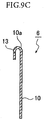
Figure 9C is an enlarged sectional view ofFigure 9B taken along line A-A'. -
Figure 10 is a perspective view illustrating a frusto-conical flexible printed circuit board. -
Figure 11 is a plan view showing how the flexible printed circuit board shown inFigure 10 is laid out in a material sheet. - Embodiments not covered by the claimed invention will be described below as a first to fourth embodiment.
-
Figures 1 to 4 show a first embodiment of the present invention. In the first embodiment, a light-emitting diode lamp 1 is used as an example of a lighting unit, and a lampmain body 2 is used as an example of a lighting unit main body. - As shown in
Figure 1 , the light-emitting diode lamp 1 includes the lampmain body 2, and a socket threadedportion 2a is formed at a lower portion of the lampmain body 2. At an upper portion of the lampmain body 2, aboard assembly 3 is disposed, and acover 4 made of a colorless, transparent glass or synthetic resin (or plastic) is attached so as to cover theboard assembly 3. Five light-emitting diodes 5 are attached to theboard assembly 3 such that the light-emitting diodes 5 can apply light in directions different from each other and such that respective irradiation areas of the light-emittingdiodes 5 overlap with each other at edges in a manner corresponding to lighting angles of the light-emitting diodes 5. - More specifically, as shown in
Figure 3 , theboard assembly 3 is composed of two flexible printedcircuit boards 6. The flexible printedcircuit boards 6 have the same U-shape. - As shown in
Figures 3 and4 , the flexible printedcircuit boards 6 each include abase 7 which is in the form of a flat plate having a substantially rectangular shape (i.e., a simple shape) when developed into a plane. Thebase 7 includesconnections 8 at two ends and is bent substantially at right angles along two bend lines L1 and L2 of a middle portion to form atop surface portion 9 and twoside surface portions 10. Note that the twoconnections 8 can be connected to a power supply portion (not shown) housed in the lampmain body 2. - As shown in
Figures 1 and3 , the two flexible printedcircuit boards 6 are three-dimensionally assembled such that thetop surface portions 9 cross each other substantially at right angles and such that one of thetop surface portions 9 lies on top of the other to constitute theboard assembly 3. The upper flexible printedcircuit board 6 includes one light-emittingdiode attaching portion 11 at each of respective predetermined positions of thetop surface portion 9 and twoside surface portions 10, and the respective light-emittingdiodes 5 are mounted on the light-emittingdiode attaching portions 11. The lower flexible printedcircuit board 6 includes one light-emittingdiode attaching portion 11 at each of respective predetermined positions of the twoside surface portions 10, and the respective light-emittingdiodes 5 are mounted on the light-emittingdiode attaching portions 11. - For this reason, as shown in
Figures 5A and5B , the five light-emittingdiodes 5 on theboard assembly 3 apply light in the directions different from each other and have the respective irradiation areas overlapping with each other at the edges. - As the flexible printed
circuit board 6, any flexible printed circuit board can be used as long as the flexible printedcircuit board 6 can maintain its bent shape (U-shape). Examples of the flexible printedcircuit board 6 which are excellent at maintaining a bent shape include a flexible printed circuit board which is formed by stacking, in order, a heat-conductiveadhesive layer 6b, an insulatinglayer 6c made of a polyimide film, and awiring layer 6d made of copper foil having a tensile strength of 250 MPa or less and a thickness of 50 µm or less on a heat-dissipatinglayer 6a made of copper foil having a tensile strength of 400 MPa or more and a thickness of 70 µm or more and coating and protecting, with a resist 6h, an upper portion of thewiring layer 6d exceptlands 6g where the light-emittingdiodes 5 are to be mounted, as shown inFigure 2 . Note that although if the flexible printedcircuit board 6 is subjected to heat treatment during the manufacturing process of the flexible printedcircuit board 6, the heat treatment may change the tensile strength of copper foil, the term "tensile strength" here refers to tensile strength when the flexible printedcircuit board 6 is in its finished form (after the flexible printedcircuit board 6 undergoes a thermal history if the flexible printedcircuit board 6 is subjected to heat treatment). - As described above, since the plurality of light-emitting
diodes 5 are attached to thelands 6g of the flexible printedcircuit boards 6 of theboard assembly 3 such that the plurality of light-emittingdiodes 5 can apply light in the directions different from each other, the light-emitting diode lamp 1 can illuminate a wide range. Additionally, the plurality of light-emittingdiodes 5 are attached such that the irradiation areas of the light-emittingdiodes 5 overlap with each other at the edges, occurrence of blind spots can be prevented. - The shape of each flexible printed
circuit board 6 when developed into a plane has a simple shape, i.e., a substantially rectangular shape. If the flexible printedcircuit boards 6 are laid out in amaterial sheet 12, as shown inFigure 4 , the number of flexible printedcircuit boards 6 that can be laid out is large (as large as twelve inFigure 4 ), and the yield rate of a material is high. Additionally, as described above, the two flexible printedcircuit boards 6 have the same shape (U-shape) and, even when developed into a plane, have the same shape (substantially rectangular shape). There is no need to distinguish the two flexible printedcircuit boards 6. Accordingly, the manufacturing costs of the flexible printedcircuit board 6 can be reduced, which in turn leads to a reduction in the manufacturing costs of the light-emitting diode lamp 1. - Use of a flexible printed circuit board including the heat-dissipating
layer 6a made of copper foil having a thickness of 70 µm or more as the flexible printedcircuit board 6 allows sufficient dissipation of heat generated by the light-emittingdiodes 5. - Use of a flexible printed circuit board including the heat-dissipating
layer 6a made of copper foil having a tensile strength of 400 MPa or more as the flexible printedcircuit board 6 makes the copper foil as the heat-dissipatinglayer 6a unlikely to be unevenly deformed (plastically deformed), e.g., during the manufacturing process of the flexible printedcircuit board 6 and allows low-cost maintenance of the flatness of the flexible printedcircuit board 6. That is, even when thick copper foil is adopted as the heat-dissipatinglayer 6a, if the copper foil is soft, the heat-dissipatinglayer 6a is easily unevenly deformed to lose its flatness. Accordingly, the heat-dissipatinglayer 6a needs to be planarized by using a corrective jig in order to prevent a failure from occurring when the light-emittingdiodes 5 are mounted. However, adoption of copper foil having a tensile strength of 400 MPa or more and high elasticity as the heat-dissipatinglayer 6a prevents uneven deformation of the heat-dissipatinglayer 6a and eliminates the need to planarize the heat-dissipatinglayer 6a. This allows a reduction in the manufacturing costs of the flexible printedcircuit board 6. Additionally, even after the flexible printedcircuit board 6 is bent in a U-shape, the heat-dissipatinglayer 6a can serve as a skeletal frame which maintains the U-shape. Accordingly, when a circuit element (not shown) is mounted on the flexible printedcircuit board 6, an attachment position and an attachment posture of the circuit element can be stabilized. -
Figure 6 shows a second embodiment of the present invention. - In the second embodiment, as shown in
Figure 6 , the number of flexible printedcircuit boards 6 constituting aboard assembly 3 is three, andtop surface portions 9 of the flexible printedcircuit boards 6 are made to cross each other substantially at 60°. Note that a top one of the three flexible printedcircuit boards 6 includes one light-emittingdiode attaching portion 11 at each of respective predetermined positions of thetop surface portion 9 and twoside surface portions 10. The other two flexible printedcircuit boards 6 each include one light-emittingdiode attaching portion 11 at each of respective predetermined positions of the twoside surface portions 10. The remainder of the configuration is the same as that in the first embodiment described above. Note that the same members as those in the first embodiment are denoted by the same reference numerals and that a description thereof will be omitted. - Accordingly, the second embodiment achieves the same working-effects as those of the first embodiment. In addition, since the
top surface portions 9 of the three flexible printedcircuit boards 6 cross each other at 60° in the second embodiment, light can be applied to surroundings more equally than in the first embodiment where thetop surface portions 9 of the two flexible printedcircuit boards 6 cross each other substantially at right angles. Moreover, the amount of light can be made larger in the second embodiment than in the first embodiment by an amount corresponding to an increase in the number of light-emittingdiodes 5 to be attached. - In the second embodiment, the light-emitting 5 diodes on the
board assembly 3 are arranged such that the light-emittingdiodes 5 apply light in directions different from each other and such that irradiation areas of the light-emittingdiodes 5 overlap with each other at edges, as in the first embodiment (seeFigures 5A and5B ). With this configuration, in the second embodiment as well, occurrence of blind spots can be prevented. - Examples of the flexible printed
circuit board 6 according to the second embodiment include a flexible printed circuit board (seeFigure 2 ) which is formed by stacking, in order, a heat-conductiveadhesive layer 6b, an insulatinglayer 6c made of a polyimide film, and awiring layer 6d made of copper foil having a tensile strength of 250 MPa or less and a thickness of 50 µm or less on a heat-dissipatinglayer 6a made of copper foil having a tensile strength of 400 MPa or more and a thickness of 70 µm or more and coating and protecting, with a resist 6h, an upper portion of thewiring layer 6d exceptlands 6g where the light-emittingdiodes 5 are to be mounted, as in the first embodiment. Note that the term "tensile strength" in the second embodiment refers to tensile strength when the flexible printedcircuit board 6 is in its finished form (after the flexible printedcircuit board 6 undergoes a thermal history if the flexible printedcircuit board 6 is subjected to heat treatment), as in the first embodiment. - As in the first embodiment, use of a flexible printed circuit board including the heat-dissipating
layer 6a made of copper foil having a thickness of 70 µm or more as the flexible printedcircuit board 6 allows sufficient dissipation of heat generated by the light-emittingdiodes 5. Also, as in the first embodiment, use of the heat-dissipatinglayer 6a made of copper foil having a tensile strength of 400 MPa or more makes the copper foil as the heat-dissipatinglayer 6a unlikely to be unevenly deformed (plastically deformed), e.g., during the manufacturing process of the flexible printedcircuit board 6 and allows low-cost maintenance of the flatness of the flexible printedcircuit board 6. - The
board assembly 3 according to the second embodiment can also be mounted in a lighting unit 1 (seeFigure 1 ) which is the same as that in the first embodiment. -
Figure 7 shows a third embodiment of the present invention. - In the third embodiment, as shown in
Figure 7 , a flexible printedcircuit board 6 has a larger width, and an angle with respect to atop surface portion 9 at whichside surface portions 10 are bent is an obtuse angle (e.g., about 120°). The remainder of the configuration is the same as that in the first embodiment described above. Note that the same members as those in the first embodiment are denoted by the same reference numerals and that a description thereof will be omitted. - Accordingly, the third embodiment achieves the same working-effects as those of the first embodiment. In addition, since the
side surface portions 10 of the flexible printedcircuit boards 6 are all tilted so as to face obliquely upward in the third embodiment, space above the flexible printedcircuit boards 6 can be illuminated more satisfactorily than in the first embodiment. - In the third embodiment, light-emitting
diodes 5 on aboard assembly 3 are arranged such that the light-emittingdiodes 5 apply light in directions different from each other and such that irradiation areas of the light-emittingdiodes 5 overlap with each other at edges, as in the first embodiment (seeFigures 5A and5B ). With this configuration, in the third embodiment as well, occurrence of blind spots can be prevented. - Examples of the flexible printed
circuit board 6 according to the third embodiment include a flexible printed circuit board (seeFigure 2 ) which is formed by stacking, in order, a heat-conductiveadhesive layer 6b, an insulatinglayer 6c made of a polyimide film, and awiring layer 6d made of copper foil having a tensile strength of 250 MPa or less and a thickness of 50 µm or less on a heat-dissipatinglayer 6a made of copper foil having a tensile strength of 400 MPa or more and a thickness of 70 µm or more and coating and protecting, with a resist 6h, an upper portion of thewiring layer 6d exceptlands 6g where the light-emittingdiodes 5 are to be mounted, as in the first embodiment. Note that the term "tensile strength" in the third embodiment refers to tensile strength when the flexible printedcircuit board 6 is in its finished form (after the flexible printedcircuit board 6 undergoes a thermal history if the flexible printedcircuit board 6 is subjected to heat treatment), as in the first embodiment. - As in the first embodiment, use of a flexible printed circuit board including the heat-dissipating
layer 6a made of copper foil having a thickness of 70 µm or more as the flexible printedcircuit board 6 allows sufficient dissipation of heat generated by the light-emittingdiodes 5. Also, as in the first embodiment, use of the heat-dissipatinglayer 6a made of copper foil having a tensile strength of 400 MPa or more makes the copper foil as the heat-dissipatinglayer 6a unlikely to be unevenly deformed (plastically deformed), e.g., during the manufacturing process of the flexible printedcircuit board 6 and allows low-cost maintenance of the flatness of the flexible printedcircuit board 6. - The
board assembly 3 according to the third embodiment can also be mounted in a lighting unit 1 (seeFigure 1 ) which is the same as that in the first embodiment. -
Figures 8A and8B show a fourth embodiment of the present invention. - In the fourth embodiment, as shown in
Figure 8A and8B , the shape of aside surface portion 10 of a flexible printedcircuit board 6 is substantially trapezoidal. The remainder of the configuration is the same as that in the third embodiment described above. Note that the same members as those in the third embodiment are denoted by the same reference numerals and that a description thereof will be omitted. - Accordingly, the fourth embodiment achieves the same working-effects as those of the third embodiment. In addition, the width of each
side surface portion 10 in each flexible printedcircuit board 6 increases from atop surface portion 9 toward aconnection 8 in the fourth embodiment, as shown inFigures 8A and8B . Accordingly, heat deterioration of light-emittingdiodes 5 can be inhibited by efficiently transferring heat generated by the light-emittingdiodes 5 to a lampmain body 2. Moreover, in the fourth embodiment, an angle with respect to thetop surface portion 9 of each flexible printedcircuit board 6 at which theside surface portions 10 are bent is about 120°, and corresponding edges of adjacent ones of theside surface portions 10 are in contact with each other. This configuration allows closing of gaps between theside surface portions 10 of the two flexible printedcircuit boards 6. For this reason, space above the flexible printedcircuit boards 6 can be further satisfactorily illuminated without letting dust enter aboard assembly 3. - In the fourth embodiment, the light-emitting diodes on the
board assembly 3 are arranged such that the light-emitting diodes apply light in directions different from each other and such that irradiation areas of the light-emitting diodes overlap with each other at edges, as in the first embodiment (seeFigures 5A and5B ). With this configuration, in the fourth embodiment as well, occurrence of blind spots can be prevented. - Examples of the flexible printed
circuit board 6 according to the fourth embodiment include a flexible printed circuit board (seeFigure 2 ) which is formed by stacking, in order, a heat-conductiveadhesive layer 6b, an insulatinglayer 6c made of a polyimide film, and awiring layer 6d made of copper foil having a tensile strength of 250 MPa or less and a thickness of 50 µm or less on a heat-dissipatinglayer 6a made of copper foil having a tensile strength of 400 MPa or more and a thickness of 70 µm or more and coating and protecting, with a resist 6h, an upper portion of thewiring layer 6d exceptlands 6g where the light-emittingdiodes 5 are to be mounted, as in the first embodiment. Note that the term "tensile strength" in the fourth embodiment refers to tensile strength when the flexible printedcircuit board 6 is in its finished form (after the flexible printedcircuit board 6 undergoes a thermal history if the flexible printedcircuit board 6 is subjected to heat treatment), as in the first embodiment. - As in the first embodiment, use of a flexible printed circuit board including the heat-dissipating
layer 6a made of copper foil having a thickness of 70 µm or more as the flexible printedcircuit board 6 allows sufficient dissipation of heat generated by the light-emittingdiodes 5. Also, as in the first embodiment, use of the heat-dissipatinglayer 6a made of copper foil having a tensile strength of 400 MPa or more makes the copper foil as the heat-dissipatinglayer 6a unlikely to be unevenly deformed (plastically deformed), e.g., during the manufacturing process of the flexible printedcircuit board 6 and allows low-cost maintenance of the flatness of the flexible printedcircuit board 6. - The
board assembly 3 according to the fourth embodiment can also be mounted in a lighting unit 1 (seeFigure 1 ) which is the same as that in the first embodiment. -
Figures 9A to 9C show a fifth embodiment of the present invention. - In the fifth embodiment, as shown in
Figures 9A to 9C , arib 13 is formed along aside edge 10a of aside surface portion 10 of a flexible printedcircuit board 6. The remainder of the configuration is the same as that in the first embodiment described above. Note that the same members as those in the first embodiment are denoted by the same reference numerals and that a description thereof will be omitted. - Accordingly, the fifth embodiment achieves the same working-effects as those of the first embodiment. In addition, since each
side surface portion 10 of the flexible printedcircuit board 6 is reinforced with therib 13 in the fifth embodiment, the durability of the flexible printedcircuit board 6 can be enhanced. - The flexible printed
circuit board 6 including theribs 13 can be applied to any of theboard assemblies 3 according to the first to fourth embodiments. - Note that the above first to fifth embodiments each have described a case where one light-emitting
diode 5 is attached to each of thetop surface portion 9 andside surface portions 10 of the flexible printedcircuit board 6. The number of light-emittingdiodes 5 to be attached to each of thetop surface portion 9 andside surface portions 10, however, is not limited to one. - Additionally, the first to fifth embodiments each have described the light-emitting diode lamp 1 including the flexible printed
circuit board 6 bent at two points of a middle portion of thebase 7. However, thebase 7 may be bent at three or more points of a middle portion as long as thetop surface portion 9 andside surface portions 10 are formed in the flexible printedcircuit board 6. - Moreover, the first and third to fifth embodiments each have described a case where the
board assembly 3 is composed of the two flexible printedcircuit boards 6, and the second embodiment has described a case where theboard assembly 3 is composed of the three flexible printedcircuit boards 6. The number of flexible printedcircuit boards 6 constituting theboard assembly 3, however, is not limited to two or three. The number may be four or more. - Furthermore, the first to fifth embodiments each have described a case where the light-emitting diode lamp 1 is adopted as a lighting unit. However, the present invention can also be applied to a lighting unit other than the light-emitting diode lamp 1.
- The present invention can be applied to a wide range of lighting units which use a light-emitting diode as a light source, such as an electric bulb, a straight luminaire (e.g., a fluorescent lamp), a ceiling light, a lantern, a plant growth light, lighting machinery in a refrigerator-freezer, a portable flashlight, a headlight of a bicycle, various types of lights of an automobile (e.g., an interior light, a side marker light, a turn-signal light, and a parking light), a guide light, an emergency light, a warning light, a dental curing light, a garden lantern, a paper lantern, and a lamp for an aquarium.
-
- 1
- light-emitting diode lamp (lighting unit)
- 2
- lamp main body (lighting unit main body)
- 3
- board assembly
- 5
- light-emitting diode
- 6
- flexible printed circuit board
- 6a
- heat-dissipating layer
- 7
- base
- 8
- connection
- 9
- top surface portion
- 10
- side surface portion
- 10a
- side edge
- 11
- light-emitting diode attaching portion
- 13
- rib
Claims (7)
- A lightning unit (1) provided with a light unit main body (2) and a board assembly (3) disposed in the light unit main body (2), the board assembly (3) comprising a plurality of flexible printed circuit boards (6) to which a light-emitting diode is attached,
wherein each of the flexible printed circuit boards (6) includes a base (7) in the form of a flat plate, respective connections (8) to a power supply portion of the lighting unit (1) are provided at two ends of the base (7), and the base (7) is bent at a plurality of points of a middle portion to form a top surface portion (9) and side surface portions (10),
the flexible printed circuit boards (6) have substantially same shapes, are three-dimensionally assembled such that the top surface portions (9) cross each other and such that one of the top surface portions (9) lies on top of another,
the connections of the flexible printed circuit boards (6) are disposed in the light unit main body (2) and connected to a power supply portion housed in the light unit main body (2), and
a rib (13) is formed along a side edge of each of the side surface portions in each flexible printed circuit board (6). - The lighting unit (1) according to claim 1, wherein each flexible printed circuit board (6) includes a heat-dissipating layer (6a) which is made of copper foil having a tensile strength of 400 MPa or more and a thickness of 70 µm or more.
- The lighting unit (1) according to claim 1, wherein a top one of the plurality of flexible printed circuit boards (6) includes a light-emitting diode attaching portion (11) to which the light-emitting diode (5) is attached at each of the top surface portion (9) and the side surface portions (10), and the other flexible printed circuit boards (6) each include a light-emitting diode attaching portion (11) to which the light-emitting diode (5) is attached at each of the side surface portions (10).
- The lighting unit (1) according to claim 3, wherein the light-emitting diode attaching portions (11) of the plurality of flexible printed circuit boards (6) are set such that irradiation areas of the light-emitting diodes (5) overlap with each other at edges when the light-emitting diodes (5) are attached.
- The lighting unit (1) according to claim 1, wherein each flexible printed circuit board (6) includes a top surface portion (9) having a substantially rectangular shape provided at a central portion and the respective side surface portions (10) having a substantially rectangular shape provided so as to extend from two sides of the top surface portion (9) in substantially perpendicular directions.
- The lighting unit (1) according to claim 1, wherein each flexible printed circuit board includes a top surface portion (9) having a substantially rectangular shape provided at a central portion and the respective side surface portions (10) having a substantially rectangular shape provided so as to extend from two sides of the top surface portion (9) in directions which form obtuse angles with the top surface portion (9).
- The lighting unit (1) according to claim 1, wherein each flexible printed circuit board (6) includes a top surface portion (9) having a substantially rectangular shape provided at a central portion and the respective side surface portions (10) having a substantially trapezoidal shape provided so as to extend from two sides of the top surface portion (9) in directions which form obtuse angles with the top surface portion (9), and
a gap between adjacent ones of the side surface portions (10) is closed by bringing corresponding edges of the adjacent side surface portions into contact with each other.
Applications Claiming Priority (2)
| Application Number | Priority Date | Filing Date | Title |
|---|---|---|---|
| JP2011092708A JP5750297B2 (en) | 2011-04-19 | 2011-04-19 | Substrate assembly and lighting device |
| PCT/JP2011/079159 WO2012144109A1 (en) | 2011-04-19 | 2011-12-16 | Circuit board assembly and lighting device |
Publications (3)
| Publication Number | Publication Date |
|---|---|
| EP2570720A1 EP2570720A1 (en) | 2013-03-20 |
| EP2570720A4 EP2570720A4 (en) | 2014-04-02 |
| EP2570720B1 true EP2570720B1 (en) | 2016-03-09 |
Family
ID=47041246
Family Applications (1)
| Application Number | Title | Priority Date | Filing Date |
|---|---|---|---|
| EP11863822.0A Active EP2570720B1 (en) | 2011-04-19 | 2011-12-16 | Circuit board assembly and lighting device |
Country Status (5)
| Country | Link |
|---|---|
| US (1) | US8545056B2 (en) |
| EP (1) | EP2570720B1 (en) |
| JP (1) | JP5750297B2 (en) |
| TW (1) | TWI557363B (en) |
| WO (1) | WO2012144109A1 (en) |
Families Citing this family (50)
| Publication number | Priority date | Publication date | Assignee | Title |
|---|---|---|---|---|
| JP2735866B2 (en) | 1989-03-22 | 1998-04-02 | 日本放送協会 | How to search database data |
| JP2013526761A (en) * | 2010-05-11 | 2013-06-24 | ポリブライト・インターナショナル,インコーポレーテッド | High-intensity LED replacement of incandescent lamps |
| US8858015B2 (en) * | 2011-06-07 | 2014-10-14 | Pivot International | Solar collection and illumination apparatus |
| US9194556B1 (en) * | 2012-02-22 | 2015-11-24 | Theodore G. Nelson | Method of producing LED lighting apparatus and apparatus produced thereby |
| US9125255B2 (en) | 2012-05-03 | 2015-09-01 | Abl Ip Holding Llc | Networked architecture for system of lighting devices having sensors, for intelligent applications |
| CN103032734A (en) * | 2012-12-06 | 2013-04-10 | 中山市美耐特光电有限公司 | A kind of LED light bulb |
| JP6191224B2 (en) | 2013-05-10 | 2017-09-06 | 日亜化学工業株式会社 | WIRING BOARD AND LIGHT EMITTING DEVICE USING THE SAME |
| RU2658339C2 (en) * | 2013-05-14 | 2018-06-20 | Филипс Лайтинг Холдинг Б.В. | Illumination device and method of manufacturing an illumination device |
| US20140340873A1 (en) * | 2013-05-20 | 2014-11-20 | Ko-Chun Chen | Bendable heat readiating composite and backlight unit having the same |
| US9310031B2 (en) | 2013-06-06 | 2016-04-12 | Interlight Optotech Corporation | Light emitting diode bulb |
| KR101325080B1 (en) * | 2013-07-01 | 2013-11-05 | 주식회사 디에스이 | A led candle lamp |
| CN103574368B (en) * | 2013-11-12 | 2015-11-04 | 无锡天地合同能源管理有限公司 | LEDbulb lamp |
| RU2537828C1 (en) * | 2014-01-09 | 2015-01-10 | Общество с ограниченной ответственностью "ДиС ПЛЮС" (ООО "ДиС ПЛЮС") | Light-emitting diode lamp |
| WO2015138417A1 (en) | 2014-03-10 | 2015-09-17 | Forever Bulb, Llc | Led light bulb with internal flexible heatsink and circuit |
| US9328873B2 (en) * | 2014-03-21 | 2016-05-03 | Tai-Hsiang Huang | Light bulb having light emitting diodes connected to at least two circuit boards |
| JP6310311B2 (en) * | 2014-04-17 | 2018-04-11 | 株式会社小糸製作所 | Vehicle lighting |
| JP2016012467A (en) * | 2014-06-28 | 2016-01-21 | 岩崎電気株式会社 | Hermetically sealed LED lamp |
| CN105276397A (en) * | 2014-07-11 | 2016-01-27 | 晋挥电子有限公司 | All around light LED lamps |
| WO2016020782A1 (en) * | 2014-08-05 | 2016-02-11 | Osram Gmbh | A support structure for lighting devices, corresponding device and method |
| JP6392637B2 (en) * | 2014-11-07 | 2018-09-19 | 住友電工プリントサーキット株式会社 | LED module and LED lighting apparatus |
| CN105698037A (en) * | 2014-11-25 | 2016-06-22 | 鸿富锦精密工业(深圳)有限公司 | Lamp |
| KR20160108867A (en) * | 2015-03-09 | 2016-09-21 | 엘이디라이텍(주) | Flexible printed circuit board for LED lamp |
| CN104696765B (en) * | 2015-03-31 | 2017-09-01 | 东莞市闻誉实业有限公司 | Indoor lighting device |
| CN104696766B (en) * | 2015-03-31 | 2017-11-07 | 东莞市闻誉实业有限公司 | lamps |
| CN108027121A (en) * | 2015-09-04 | 2018-05-11 | 飞利浦照明控股有限公司 | Lighting apparatus with the flexible electrical travel permit wound around supporting item |
| US20170122498A1 (en) * | 2015-10-30 | 2017-05-04 | General Electric Company | Lamp design with led stem structure |
| CN105333326A (en) * | 2015-12-11 | 2016-02-17 | 江苏鸿佳电子科技有限公司 | Lantern type light-source bulb lamp |
| DE102016105313A1 (en) * | 2016-03-22 | 2017-09-28 | Osram Opto Semiconductors Gmbh | FILAMENT WITH LIGHT-EMITTING SEMICONDUCTOR CHIPS, LAMPS AND METHOD FOR PRODUCING A FILAMENT |
| CN109076693B (en) * | 2016-04-26 | 2021-09-03 | 昕诺飞控股有限公司 | Flexible solid state lighting strip |
| CN105972461A (en) * | 2016-06-30 | 2016-09-28 | 浙江生辉照明有限公司 | LED light source module and LED lamp |
| CN106195679A (en) * | 2016-06-30 | 2016-12-07 | 浙江生辉照明有限公司 | A kind of LED |
| CN106015984A (en) * | 2016-06-30 | 2016-10-12 | 浙江生辉照明有限公司 | Heat sink and LED lamp |
| JP6359605B2 (en) * | 2016-11-15 | 2018-07-18 | 株式会社京写 | Printed wiring board |
| KR101909631B1 (en) * | 2017-06-01 | 2018-10-18 | (주)포인트텍 | Unit pcb for straight-type and cross-type led lighting device and led lighting device including the same |
| CN109140263B (en) * | 2017-06-14 | 2024-04-30 | 赛万特技术有限公司 | LED Light |
| EP3453958B1 (en) * | 2017-09-12 | 2020-05-20 | OSRAM GmbH | A support member for lighting devices, corresponding device and method |
| CN110375217B (en) * | 2017-09-18 | 2020-07-10 | 海门市初享工业设计有限公司 | A portable lighting device for power line maintenance |
| US10750588B2 (en) | 2018-05-04 | 2020-08-18 | Lumileds Llc | Light fixture with dynamically controllable light distribution |
| US10859757B2 (en) | 2018-05-04 | 2020-12-08 | Lumileds Llc | Light fixture with light guide and radially emitting LEDs |
| US10622405B2 (en) * | 2018-05-04 | 2020-04-14 | Lumileds Llc | Light fixture with dynamically controllable light distribution |
| US10845529B2 (en) | 2018-05-04 | 2020-11-24 | Lumileds Llc | Light engines with dynamically controllable light distribution |
| US10943945B2 (en) | 2018-05-04 | 2021-03-09 | Lumileds Llc | Light fixture with dynamically controllable light distribution |
| US10785847B2 (en) | 2018-05-04 | 2020-09-22 | Lumileds Llc | Light engines with dynamically controllable light distribution |
| US10821890B2 (en) | 2018-05-04 | 2020-11-03 | Lumileds Llc | Light engines with dynamically controllable light distribution |
| US10872923B2 (en) | 2018-05-04 | 2020-12-22 | Lumileds Llc | Light engines with dynamically controllable light distribution |
| CN110925608A (en) * | 2018-08-31 | 2020-03-27 | 黄智渊 | Electronic glow stick |
| CN109538998B (en) * | 2018-12-29 | 2024-02-06 | 广州纽威光电科技有限公司 | LED lamp |
| US11828447B2 (en) * | 2019-05-20 | 2023-11-28 | Signify Holding B.V. | Light source comprising a substrate and a heat sink structure |
| CN111089251A (en) * | 2020-01-17 | 2020-05-01 | 成都清妙创意设计有限公司 | Multifunctional garden lamp |
| JP2023136030A (en) * | 2022-03-16 | 2023-09-29 | 株式会社リコー | Three-dimentional measurement device and three-dimensional measurement system |
Citations (2)
| Publication number | Priority date | Publication date | Assignee | Title |
|---|---|---|---|---|
| US6283604B1 (en) * | 1999-09-20 | 2001-09-04 | Ching-Shin Liao | Electro luminescent illuminator |
| JP3139851U (en) * | 2007-12-11 | 2008-03-06 | 呉祖耀 | LED light |
Family Cites Families (23)
| Publication number | Priority date | Publication date | Assignee | Title |
|---|---|---|---|---|
| DE19922176C2 (en) * | 1999-05-12 | 2001-11-15 | Osram Opto Semiconductors Gmbh | Surface-mounted LED multiple arrangement and its use in a lighting device |
| KR100537897B1 (en) | 2001-04-26 | 2005-12-20 | 모리야마 산교 가부시키가이샤 | Light source coupler, illuminant device, patterned conductor, and method for manufacturing light source coupler |
| JP4076329B2 (en) | 2001-08-13 | 2008-04-16 | エイテックス株式会社 | LED bulb |
| US7380961B2 (en) | 2002-04-24 | 2008-06-03 | Moriyama Sangyo Kabushiki Kaisha | Light source coupler, illuminant device, patterned conductor, and method for manufacturing light source coupler |
| CN2637885Y (en) * | 2003-02-20 | 2004-09-01 | 高勇 | LED lamp bulb with luminous curved surface |
| US20050146884A1 (en) * | 2004-01-07 | 2005-07-07 | Goodrich Hella Aerospace Lighting Systems Gmbh | Light, particularly a warning light, for a vehicle |
| JP4903393B2 (en) * | 2005-04-27 | 2012-03-28 | 京セラ株式会社 | Light source device and liquid crystal display device |
| KR100844757B1 (en) * | 2006-08-24 | 2008-07-07 | 엘지이노텍 주식회사 | Light source device and display device using same |
| US7726836B2 (en) * | 2007-11-23 | 2010-06-01 | Taiming Chen | Light bulb with light emitting elements for use in conventional incandescent light bulb sockets |
| JP2010055993A (en) * | 2008-08-29 | 2010-03-11 | Toshiba Lighting & Technology Corp | Lighting system and luminaire |
| GB2464668A (en) * | 2008-10-20 | 2010-04-28 | Sensitive Electronic Co Ltd | Thin light emitting diode circuit substrate and lamp strip |
| JP4642129B2 (en) * | 2008-11-06 | 2011-03-02 | ローム株式会社 | LED lamp |
| DE102009009288A1 (en) * | 2009-02-17 | 2010-08-26 | Osram Gesellschaft mit beschränkter Haftung | Rigid flexible carrier plate |
| TWM376709U (en) * | 2009-09-02 | 2010-03-21 | Liquidleds Lighting Corp | Curved tubular LED lamp |
| JP2011076919A (en) * | 2009-09-30 | 2011-04-14 | World Wide Engineering Kk | Led array lighting unit, and planar indirect lighting fixture using this unit |
| US9243758B2 (en) * | 2009-10-20 | 2016-01-26 | Cree, Inc. | Compact heat sinks and solid state lamp incorporating same |
| JP5354209B2 (en) * | 2010-01-14 | 2013-11-27 | 東芝ライテック株式会社 | Light bulb shaped lamp and lighting equipment |
| DE202010005863U1 (en) * | 2010-04-20 | 2010-08-05 | LITATEK CORPORATION, Shanchung City | Construction of a ball-shaped LED light source |
| USD656112S1 (en) * | 2010-05-19 | 2012-03-20 | Nippon Mektron, Ltd. | Flexible printed circuit board |
| USD656111S1 (en) * | 2010-05-19 | 2012-03-20 | Nippon Mektron, Ltd. | Flexible printed circuit board |
| JP5662059B2 (en) * | 2010-06-04 | 2015-01-28 | パナソニックIpマネジメント株式会社 | LED lamp |
| TWM412319U (en) * | 2010-11-01 | 2011-09-21 | Parlux Optoelectronics Corp | LED illumination device |
| US8314566B2 (en) * | 2011-02-22 | 2012-11-20 | Quarkstar Llc | Solid state lamp using light emitting strips |
-
2011
- 2011-04-19 JP JP2011092708A patent/JP5750297B2/en active Active
- 2011-12-16 US US13/521,651 patent/US8545056B2/en not_active Expired - Fee Related
- 2011-12-16 WO PCT/JP2011/079159 patent/WO2012144109A1/en not_active Ceased
- 2011-12-16 EP EP11863822.0A patent/EP2570720B1/en active Active
-
2012
- 2012-04-18 TW TW101113771A patent/TWI557363B/en active
Patent Citations (2)
| Publication number | Priority date | Publication date | Assignee | Title |
|---|---|---|---|---|
| US6283604B1 (en) * | 1999-09-20 | 2001-09-04 | Ching-Shin Liao | Electro luminescent illuminator |
| JP3139851U (en) * | 2007-12-11 | 2008-03-06 | 呉祖耀 | LED light |
Also Published As
| Publication number | Publication date |
|---|---|
| US8545056B2 (en) | 2013-10-01 |
| JP5750297B2 (en) | 2015-07-15 |
| WO2012144109A1 (en) | 2012-10-26 |
| TW201305490A (en) | 2013-02-01 |
| EP2570720A1 (en) | 2013-03-20 |
| US20120287614A1 (en) | 2012-11-15 |
| JP2012226934A (en) | 2012-11-15 |
| EP2570720A4 (en) | 2014-04-02 |
| TWI557363B (en) | 2016-11-11 |
Similar Documents
| Publication | Publication Date | Title |
|---|---|---|
| US8545056B2 (en) | LED flexible board assembly and lighting unit | |
| JP5081307B2 (en) | Optical unit positioning device | |
| US9291316B2 (en) | Integrated linear light engine | |
| CN101535710B (en) | The illuminator of flexible shape | |
| US7988321B2 (en) | LED lamp | |
| US6371637B1 (en) | Compact, flexible, LED array | |
| US20140168975A1 (en) | Lighting fixture with flexible lens sheet | |
| US7918596B2 (en) | Warning light | |
| EP2280212B1 (en) | Lighting device | |
| CA2914645C (en) | Ultrathin led light engine | |
| KR100951650B1 (en) | LED lighting | |
| US20110204393A1 (en) | Led lamp | |
| US9022603B1 (en) | Systems, methods, and devices for sealing LED light sources in a light module | |
| US9719636B2 (en) | LED lighting device | |
| JP3163443U (en) | LED lighting device | |
| JP7066070B2 (en) | Flexible printed circuit board assembly | |
| US20210351228A1 (en) | Light-emitting device, and method for producing same | |
| KR20100044632A (en) | Lighting apparatus having led and circuit module therefor | |
| RU118025U1 (en) | LED LAMP | |
| CN223579756U (en) | Lenses and lamps | |
| KR20100009474A (en) | Lamp device using led | |
| KR20200058785A (en) | An LED lighting device including a holder for inhibiting warpage | |
| EP3399230B1 (en) | Lighting module, method for manufacturing the same and luminous signage device comprising such lighting module | |
| CN120548436A (en) | Light-emitting devices | |
| KR20180124209A (en) | Lighting device |
Legal Events
| Date | Code | Title | Description |
|---|---|---|---|
| PUAI | Public reference made under article 153(3) epc to a published international application that has entered the european phase |
Free format text: ORIGINAL CODE: 0009012 |
|
| 17P | Request for examination filed |
Effective date: 20121116 |
|
| AK | Designated contracting states |
Kind code of ref document: A1 Designated state(s): AL AT BE BG CH CY CZ DE DK EE ES FI FR GB GR HR HU IE IS IT LI LT LU LV MC MK MT NL NO PL PT RO RS SE SI SK SM TR |
|
| A4 | Supplementary search report drawn up and despatched |
Effective date: 20140303 |
|
| RIC1 | Information provided on ipc code assigned before grant |
Ipc: F21V 29/00 20060101ALI20140225BHEP Ipc: F21S 2/00 20060101ALI20140225BHEP Ipc: F21V 19/00 20060101AFI20140225BHEP Ipc: H05K 1/05 20060101ALI20140225BHEP Ipc: F21K 99/00 20100101ALI20140225BHEP Ipc: H01L 33/48 20100101ALI20140225BHEP Ipc: F21V 23/00 20060101ALI20140225BHEP Ipc: H05K 1/14 20060101ALI20140225BHEP |
|
| DAX | Request for extension of the european patent (deleted) | ||
| 17Q | First examination report despatched |
Effective date: 20150120 |
|
| GRAP | Despatch of communication of intention to grant a patent |
Free format text: ORIGINAL CODE: EPIDOSNIGR1 |
|
| INTG | Intention to grant announced |
Effective date: 20150811 |
|
| GRAS | Grant fee paid |
Free format text: ORIGINAL CODE: EPIDOSNIGR3 |
|
| GRAA | (expected) grant |
Free format text: ORIGINAL CODE: 0009210 |
|
| AK | Designated contracting states |
Kind code of ref document: B1 Designated state(s): AL AT BE BG CH CY CZ DE DK EE ES FI FR GB GR HR HU IE IS IT LI LT LU LV MC MK MT NL NO PL PT RO RS SE SI SK SM TR |
|
| REG | Reference to a national code |
Ref country code: GB Ref legal event code: FG4D |
|
| REG | Reference to a national code |
Ref country code: AT Ref legal event code: REF Ref document number: 779799 Country of ref document: AT Kind code of ref document: T Effective date: 20160315 Ref country code: CH Ref legal event code: EP |
|
| REG | Reference to a national code |
Ref country code: IE Ref legal event code: FG4D |
|
| REG | Reference to a national code |
Ref country code: DE Ref legal event code: R096 Ref document number: 602011023939 Country of ref document: DE |
|
| REG | Reference to a national code |
Ref country code: LT Ref legal event code: MG4D |
|
| REG | Reference to a national code |
Ref country code: NL Ref legal event code: MP Effective date: 20160309 |
|
| PG25 | Lapsed in a contracting state [announced via postgrant information from national office to epo] |
Ref country code: GR Free format text: LAPSE BECAUSE OF FAILURE TO SUBMIT A TRANSLATION OF THE DESCRIPTION OR TO PAY THE FEE WITHIN THE PRESCRIBED TIME-LIMIT Effective date: 20160610 Ref country code: HR Free format text: LAPSE BECAUSE OF FAILURE TO SUBMIT A TRANSLATION OF THE DESCRIPTION OR TO PAY THE FEE WITHIN THE PRESCRIBED TIME-LIMIT Effective date: 20160309 Ref country code: FI Free format text: LAPSE BECAUSE OF FAILURE TO SUBMIT A TRANSLATION OF THE DESCRIPTION OR TO PAY THE FEE WITHIN THE PRESCRIBED TIME-LIMIT Effective date: 20160309 Ref country code: NO Free format text: LAPSE BECAUSE OF FAILURE TO SUBMIT A TRANSLATION OF THE DESCRIPTION OR TO PAY THE FEE WITHIN THE PRESCRIBED TIME-LIMIT Effective date: 20160609 Ref country code: ES Free format text: LAPSE BECAUSE OF FAILURE TO SUBMIT A TRANSLATION OF THE DESCRIPTION OR TO PAY THE FEE WITHIN THE PRESCRIBED TIME-LIMIT Effective date: 20160309 |
|
| REG | Reference to a national code |
Ref country code: AT Ref legal event code: MK05 Ref document number: 779799 Country of ref document: AT Kind code of ref document: T Effective date: 20160309 |
|
| PG25 | Lapsed in a contracting state [announced via postgrant information from national office to epo] |
Ref country code: LT Free format text: LAPSE BECAUSE OF FAILURE TO SUBMIT A TRANSLATION OF THE DESCRIPTION OR TO PAY THE FEE WITHIN THE PRESCRIBED TIME-LIMIT Effective date: 20160309 Ref country code: PL Free format text: LAPSE BECAUSE OF FAILURE TO SUBMIT A TRANSLATION OF THE DESCRIPTION OR TO PAY THE FEE WITHIN THE PRESCRIBED TIME-LIMIT Effective date: 20160309 Ref country code: NL Free format text: LAPSE BECAUSE OF FAILURE TO SUBMIT A TRANSLATION OF THE DESCRIPTION OR TO PAY THE FEE WITHIN THE PRESCRIBED TIME-LIMIT Effective date: 20160309 Ref country code: RS Free format text: LAPSE BECAUSE OF FAILURE TO SUBMIT A TRANSLATION OF THE DESCRIPTION OR TO PAY THE FEE WITHIN THE PRESCRIBED TIME-LIMIT Effective date: 20160309 Ref country code: SE Free format text: LAPSE BECAUSE OF FAILURE TO SUBMIT A TRANSLATION OF THE DESCRIPTION OR TO PAY THE FEE WITHIN THE PRESCRIBED TIME-LIMIT Effective date: 20160309 Ref country code: LV Free format text: LAPSE BECAUSE OF FAILURE TO SUBMIT A TRANSLATION OF THE DESCRIPTION OR TO PAY THE FEE WITHIN THE PRESCRIBED TIME-LIMIT Effective date: 20160309 |
|
| PG25 | Lapsed in a contracting state [announced via postgrant information from national office to epo] |
Ref country code: IS Free format text: LAPSE BECAUSE OF FAILURE TO SUBMIT A TRANSLATION OF THE DESCRIPTION OR TO PAY THE FEE WITHIN THE PRESCRIBED TIME-LIMIT Effective date: 20160709 Ref country code: EE Free format text: LAPSE BECAUSE OF FAILURE TO SUBMIT A TRANSLATION OF THE DESCRIPTION OR TO PAY THE FEE WITHIN THE PRESCRIBED TIME-LIMIT Effective date: 20160309 |
|
| PG25 | Lapsed in a contracting state [announced via postgrant information from national office to epo] |
Ref country code: RO Free format text: LAPSE BECAUSE OF FAILURE TO SUBMIT A TRANSLATION OF THE DESCRIPTION OR TO PAY THE FEE WITHIN THE PRESCRIBED TIME-LIMIT Effective date: 20160309 Ref country code: AT Free format text: LAPSE BECAUSE OF FAILURE TO SUBMIT A TRANSLATION OF THE DESCRIPTION OR TO PAY THE FEE WITHIN THE PRESCRIBED TIME-LIMIT Effective date: 20160309 Ref country code: CZ Free format text: LAPSE BECAUSE OF FAILURE TO SUBMIT A TRANSLATION OF THE DESCRIPTION OR TO PAY THE FEE WITHIN THE PRESCRIBED TIME-LIMIT Effective date: 20160309 Ref country code: PT Free format text: LAPSE BECAUSE OF FAILURE TO SUBMIT A TRANSLATION OF THE DESCRIPTION OR TO PAY THE FEE WITHIN THE PRESCRIBED TIME-LIMIT Effective date: 20160711 Ref country code: SK Free format text: LAPSE BECAUSE OF FAILURE TO SUBMIT A TRANSLATION OF THE DESCRIPTION OR TO PAY THE FEE WITHIN THE PRESCRIBED TIME-LIMIT Effective date: 20160309 Ref country code: SM Free format text: LAPSE BECAUSE OF FAILURE TO SUBMIT A TRANSLATION OF THE DESCRIPTION OR TO PAY THE FEE WITHIN THE PRESCRIBED TIME-LIMIT Effective date: 20160309 |
|
| REG | Reference to a national code |
Ref country code: DE Ref legal event code: R097 Ref document number: 602011023939 Country of ref document: DE |
|
| PG25 | Lapsed in a contracting state [announced via postgrant information from national office to epo] |
Ref country code: IT Free format text: LAPSE BECAUSE OF FAILURE TO SUBMIT A TRANSLATION OF THE DESCRIPTION OR TO PAY THE FEE WITHIN THE PRESCRIBED TIME-LIMIT Effective date: 20160309 Ref country code: BE Free format text: LAPSE BECAUSE OF FAILURE TO SUBMIT A TRANSLATION OF THE DESCRIPTION OR TO PAY THE FEE WITHIN THE PRESCRIBED TIME-LIMIT Effective date: 20160309 |
|
| PLBE | No opposition filed within time limit |
Free format text: ORIGINAL CODE: 0009261 |
|
| STAA | Information on the status of an ep patent application or granted ep patent |
Free format text: STATUS: NO OPPOSITION FILED WITHIN TIME LIMIT |
|
| PG25 | Lapsed in a contracting state [announced via postgrant information from national office to epo] |
Ref country code: DK Free format text: LAPSE BECAUSE OF FAILURE TO SUBMIT A TRANSLATION OF THE DESCRIPTION OR TO PAY THE FEE WITHIN THE PRESCRIBED TIME-LIMIT Effective date: 20160309 |
|
| 26N | No opposition filed |
Effective date: 20161212 |
|
| PG25 | Lapsed in a contracting state [announced via postgrant information from national office to epo] |
Ref country code: BG Free format text: LAPSE BECAUSE OF FAILURE TO SUBMIT A TRANSLATION OF THE DESCRIPTION OR TO PAY THE FEE WITHIN THE PRESCRIBED TIME-LIMIT Effective date: 20160609 |
|
| PG25 | Lapsed in a contracting state [announced via postgrant information from national office to epo] |
Ref country code: SI Free format text: LAPSE BECAUSE OF FAILURE TO SUBMIT A TRANSLATION OF THE DESCRIPTION OR TO PAY THE FEE WITHIN THE PRESCRIBED TIME-LIMIT Effective date: 20160309 |
|
| REG | Reference to a national code |
Ref country code: CH Ref legal event code: PL |
|
| REG | Reference to a national code |
Ref country code: DE Ref legal event code: R082 Ref document number: 602011023939 Country of ref document: DE Representative=s name: KLUNKER IP PATENTANWAELTE PARTG MBB, DE |
|
| GBPC | Gb: european patent ceased through non-payment of renewal fee |
Effective date: 20161216 |
|
| PG25 | Lapsed in a contracting state [announced via postgrant information from national office to epo] |
Ref country code: MC Free format text: LAPSE BECAUSE OF FAILURE TO SUBMIT A TRANSLATION OF THE DESCRIPTION OR TO PAY THE FEE WITHIN THE PRESCRIBED TIME-LIMIT Effective date: 20160309 |
|
| REG | Reference to a national code |
Ref country code: FR Ref legal event code: ST Effective date: 20170831 |
|
| REG | Reference to a national code |
Ref country code: IE Ref legal event code: MM4A |
|
| PG25 | Lapsed in a contracting state [announced via postgrant information from national office to epo] |
Ref country code: LU Free format text: LAPSE BECAUSE OF NON-PAYMENT OF DUE FEES Effective date: 20161216 Ref country code: CH Free format text: LAPSE BECAUSE OF NON-PAYMENT OF DUE FEES Effective date: 20161231 Ref country code: FR Free format text: LAPSE BECAUSE OF NON-PAYMENT OF DUE FEES Effective date: 20170102 Ref country code: LI Free format text: LAPSE BECAUSE OF NON-PAYMENT OF DUE FEES Effective date: 20161231 |
|
| PG25 | Lapsed in a contracting state [announced via postgrant information from national office to epo] |
Ref country code: GB Free format text: LAPSE BECAUSE OF NON-PAYMENT OF DUE FEES Effective date: 20161216 Ref country code: IE Free format text: LAPSE BECAUSE OF NON-PAYMENT OF DUE FEES Effective date: 20161216 |
|
| PG25 | Lapsed in a contracting state [announced via postgrant information from national office to epo] |
Ref country code: HU Free format text: LAPSE BECAUSE OF FAILURE TO SUBMIT A TRANSLATION OF THE DESCRIPTION OR TO PAY THE FEE WITHIN THE PRESCRIBED TIME-LIMIT; INVALID AB INITIO Effective date: 20111216 Ref country code: CY Free format text: LAPSE BECAUSE OF FAILURE TO SUBMIT A TRANSLATION OF THE DESCRIPTION OR TO PAY THE FEE WITHIN THE PRESCRIBED TIME-LIMIT Effective date: 20160309 |
|
| PG25 | Lapsed in a contracting state [announced via postgrant information from national office to epo] |
Ref country code: TR Free format text: LAPSE BECAUSE OF FAILURE TO SUBMIT A TRANSLATION OF THE DESCRIPTION OR TO PAY THE FEE WITHIN THE PRESCRIBED TIME-LIMIT Effective date: 20160309 Ref country code: MK Free format text: LAPSE BECAUSE OF FAILURE TO SUBMIT A TRANSLATION OF THE DESCRIPTION OR TO PAY THE FEE WITHIN THE PRESCRIBED TIME-LIMIT Effective date: 20160309 |
|
| PG25 | Lapsed in a contracting state [announced via postgrant information from national office to epo] |
Ref country code: MT Free format text: LAPSE BECAUSE OF NON-PAYMENT OF DUE FEES Effective date: 20161216 |
|
| PG25 | Lapsed in a contracting state [announced via postgrant information from national office to epo] |
Ref country code: AL Free format text: LAPSE BECAUSE OF FAILURE TO SUBMIT A TRANSLATION OF THE DESCRIPTION OR TO PAY THE FEE WITHIN THE PRESCRIBED TIME-LIMIT Effective date: 20160309 |
|
| REG | Reference to a national code |
Ref country code: DE Ref legal event code: R081 Ref document number: 602011023939 Country of ref document: DE Owner name: MEKTEC CORPORATION, JP Free format text: FORMER OWNER: NIPPON MEKTRON, LTD., TOKYO, JP |
|
| PGFP | Annual fee paid to national office [announced via postgrant information from national office to epo] |
Ref country code: DE Payment date: 20251028 Year of fee payment: 15 |