EP2570546B1 - Wäschetrockner mit Wärmepumpensystem - Google Patents
Wäschetrockner mit Wärmepumpensystem Download PDFInfo
- Publication number
- EP2570546B1 EP2570546B1 EP11181841.5A EP11181841A EP2570546B1 EP 2570546 B1 EP2570546 B1 EP 2570546B1 EP 11181841 A EP11181841 A EP 11181841A EP 2570546 B1 EP2570546 B1 EP 2570546B1
- Authority
- EP
- European Patent Office
- Prior art keywords
- air duct
- evaporator
- condenser
- basement
- laundry dryer
- Prior art date
- Legal status (The legal status is an assumption and is not a legal conclusion. Google has not performed a legal analysis and makes no representation as to the accuracy of the status listed.)
- Active
Links
- 239000003507 refrigerant Substances 0.000 claims description 16
- 238000001816 cooling Methods 0.000 claims 2
- 238000010438 heat treatment Methods 0.000 claims 2
- 238000005265 energy consumption Methods 0.000 description 4
- 238000012986 modification Methods 0.000 description 2
- 230000004048 modification Effects 0.000 description 2
- XLYOFNOQVPJJNP-UHFFFAOYSA-N water Substances O XLYOFNOQVPJJNP-UHFFFAOYSA-N 0.000 description 2
- 238000005452 bending Methods 0.000 description 1
- 238000005516 engineering process Methods 0.000 description 1
Images

Classifications
-
- D—TEXTILES; PAPER
- D06—TREATMENT OF TEXTILES OR THE LIKE; LAUNDERING; FLEXIBLE MATERIALS NOT OTHERWISE PROVIDED FOR
- D06F—LAUNDERING, DRYING, IRONING, PRESSING OR FOLDING TEXTILE ARTICLES
- D06F58/00—Domestic laundry dryers
- D06F58/20—General details of domestic laundry dryers
-
- D—TEXTILES; PAPER
- D06—TREATMENT OF TEXTILES OR THE LIKE; LAUNDERING; FLEXIBLE MATERIALS NOT OTHERWISE PROVIDED FOR
- D06F—LAUNDERING, DRYING, IRONING, PRESSING OR FOLDING TEXTILE ARTICLES
- D06F58/00—Domestic laundry dryers
- D06F58/20—General details of domestic laundry dryers
- D06F58/206—Heat pump arrangements
-
- D—TEXTILES; PAPER
- D06—TREATMENT OF TEXTILES OR THE LIKE; LAUNDERING; FLEXIBLE MATERIALS NOT OTHERWISE PROVIDED FOR
- D06F—LAUNDERING, DRYING, IRONING, PRESSING OR FOLDING TEXTILE ARTICLES
- D06F58/00—Domestic laundry dryers
- D06F58/02—Domestic laundry dryers having dryer drums rotating about a horizontal axis
- D06F58/04—Details
Definitions
- the present invention relates to a laundry dryer with a heat pump system according to the preamble of claim 1.
- the heat pump technology in a laundry dryer is at present the most efficient way to dry clothes in terms of energy consumption.
- a heat pump system of the laundry dryer an air stream flows in a closed air stream circuit.
- the heat pump system includes a closed refrigerant circuit.
- the air stream is moved by a fan, passes through a laundry chamber, which is preferably formed as a rotatable laundry drum, and removes there water from wet clothes. Then, the air stream is cooled down and dehumidified in an evaporator, heated up in a condenser and re-inserted into the laundry drum again.
- the refrigerant is compressed by a compressor, condensed in the condenser, laminated in an expansion device and then vaporized in the evaporator.
- the condenser and the evaporator are components of the air stream circuit as well as the refrigerant circuit.
- the condenser and the evaporator are heat exchangers between the air stream circuit and the refrigerant circuit.
- the components of the heat pump system are placed in a basement of the laundry dryer.
- the compressor, the evaporator and the condenser are arranged in said basement below the laundry drum.
- an air duct of the air stream circuit has to pass the basement.
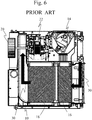
- FIG 6 illustrates a top view of the open basement of the laundry dryer according to the prior art.
- the compressor 14, the evaporator 16, the condenser 18, the fan 20 and the motor 22 are arranged in the lower casing 10 of the basement.
- the evaporator 16 and the condenser 18 are placed in a straight air duct.
- the evaporator 16 and the condenser 18 are arranged in parallel.
- the straight air duct causes that the air stream has to pass an angle at the inlet and at the outlet of said straight air duct. Such angles in the air stream circuit cause pressure drops and turbulences increasing the energy consumption and the noise.
- German patent application DE 42 12 700 A1 discloses a laundry dryer having a heat pump circuit.
- German patent application DE 10 2006 016294 A1 discloses a domestic appliance for care of items of laundry.
- Japanese patent application JP 2007 000386 A discloses a clothes dryer.
- the object of the present invention is achieved by the laundry dryer according to claim 1.
- the air duct comprises at least one curved portion, wherein the evaporator and the condenser are arranged inside said curved portion of the air duct.
- the core of the present invention is the combination of the curved portion of the air duct in the basement of the laundry dryer on the one hand and the arrangement of the evaporator and the condenser inside said curved portion of the air duct on the other hand.
- the curved portion prevents corners inside the air duct, so that pressure drops in the air duct are reduced.
- the air flow through the evaporator and condenser is optimized.
- the heat exchange between the refrigerant circuit and the air stream circuit increases.
- the dimensions of the evaporator and condenser may be reduced. This allows a redistribution of the components in the basement of the laundry dryer.
- the energy consumption of the motors for the compressor and the fan is reduced. Further, the noise of the laundry dryer is reduced.
- At least a part of the curved portion of the air duct has the structure of an arc of a circle.
- the evaporator and the condenser are inclined to each other.
- the orientations of the evaporator and condenser are adapted to the structure of the air duct.
- the continuations of the main planes of the evaporator and the condenser intersect in the centre of the circle defining the arc of the air duct.
- the main planes of the evaporator and condenser may be arranged perpendicular to the direction of the air duct.
- the fan of the air stream circuit is arranged at the end of the air duct or at the end of the curved portion of said air duct in the basement.
- the air duct or the curved portion of said air duct extends horizontally in the basement.
- the bending of the air duct extends in a horizontal plane.
- the one or more curved portions of the air duct extend substantially over the whole air duct in the basement.
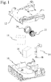
- FIG 1 illustrates an upper perspective exploded view of a basement of a laundry dryer according to a preferred embodiment of the present invention.
- the basement is provided for a laundry dryer with a heat pump system.
- the basement forms a lower portion of the laundry dryer and is arranged below a laundry drum.
- the basement advantageously includes a lower casing 10 and an upper casing 12. Further, the basement includes a compressor 14, an evaporator 16, a condenser 18, a fan 20 and a motor 22.
- the lower casing 10 and the upper casing 12 enclose the compressor 14, the evaporator 16, the condenser 18, the fan 20 and the motor 22.
- the laundry dryer comprises a closed air stream circuit.
- the air stream circuit includes the fan 20, the laundry drum, the evaporator 16 and the condenser 18.
- the heat pump system comprises a closed refrigerant circuit.
- the refrigerant circuit includes the compressor 14, the evaporator 16, the condenser 18 and an expansion device. The expansion device is not shown in FIG 1 .
- an air stream is moved by the fan 20, passes the laundry drum and removes water from wet clothes inside said laundry drum.
- the motor 22 is provided for driving the fan 20.
- the air stream is cooled down and dehumidified in the evaporator 16, heated up in the condenser 18 and re-inserted into the laundry drum again.
- the refrigerant circuit the refrigerant is compressed by the compressor 14, condensed in the condenser 18, laminated in the expansion device and vaporized in the evaporator 16.
- the evaporator 16 and the condenser 18 are heat exchangers between the air stream circuit and the refrigerant circuit.
- the air stream circuit comprises an air duct 24.
- the air duct 24 is formed by the lower casing 10 and the upper casing 12. In FIG 1 a lower part of the air duct 24 formed by the lower casing 10 is visible.
- the air duct 24 has the structure of an arc of a circle. Thus, the air duct 24 has no corners and edges.
- the evaporator 16 and the condenser 18 are arranged in the air duct 24.
- the orientations of the evaporator 16 and condenser 18 are adapted to the run of the air duct 24, so that the flow directions through the evaporator 16 and condenser 18 are substantially the same as in the air duct 24.
- the fan 20 is arranged at the end of the air duct 24.
- the structure of the curved air duct 24 and the orientations of the evaporator 16 and condenser 18 allow an improved air stream. Pressure drops and turbulences of the air stream are reduced. The noise generated by the air stream is also reduced.
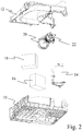
- FIG 2 illustrates a lower perspective exploded view of the basement of the laundry dryer according to the preferred embodiment of the present invention.
- the basement includes the lower casing 10 and the upper casing 12.
- the compressor 14, the evaporator 16, the condenser 18, the fan 20 and the motor 22 are enclosed by the lower casing 10 and the upper casing 12.
- the air duct 24 is formed by the lower casing 10 and the upper casing 12. In FIG 2 an upper part of the air duct 24 formed by the upper casing 12 is visible.
- the air duct 24 has the structure of an arc of a circle.
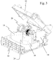
- FIG 3 illustrates a perspective view of the open basement of the laundry dryer according to the preferred embodiment of the present invention.
- the compressor 14, the evaporator 16, the condenser 18, the fan 20 and the motor 22 are arranged in the lower casing 10 and covered by the upper casing 12.
- FIG 3 clarifies the orientation of the evaporator 16 and the condenser 18 inside the air duct 24.
- the flow directions of the air stream through the evaporator 16 and condenser 18 are adapted to the flow direction in the air duct 24.
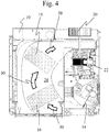
- FIG 4 illustrates a top view of the open basement of the laundry dryer according to the preferred embodiment of the present invention.
- the compressor 14, the evaporator 16, the condenser 18, the fan 20 and the motor 22 are arranged in the lower casing 10 of the basement.
- FIG 4 clarifies the orientations of the evaporator 16 and condenser 18, wherein the flow directions through the evaporator 16 and condenser 18 are substantially the same as the air flow direction in the air duct 24.
- the evaporator 16 and the condenser 18 are inclined to each other, wherein their main planes advantageously intersect in the central point of the circle defining the arc of the air duct 24.
- the arrows 30 represent the air stream through the air duct 24.
- FIG 5 illustrates a perspective view of the laundry dryer according to the preferred embodiment of the present invention.
- the laundry dryer comprises the laundry drum 26 and the basement 28.
- the laundry drum 26 is arranged in a central portion of the laundry dryer.
- the basement 28 forms a lower portion of the laundry dryer.
- the air duct 24 extends along a horizontal direction inside the basement.
- FIG 6 illustrates a top view of the open basement of the laundry dryer according to the prior art.
- the compressor 14, the evaporator 16, the condenser 18, the fan 20 and the motor 22 are arranged in the lower casing 10 of the basement.
- the evaporator 16 and the condenser 18 are placed in a straight air duct.
- the evaporator 16 and the condenser 18 are arranged in parallel.
- the straight air duct causes that the air stream has to pass an angle at the inlet band outlet of said straight air duct. Such angles in the air stream circuit cause pressure drops and turbulences increasing the energy consumption and the noise. His problems have been overcome by the present invention.
Claims (4)
- Wäschetrockner mit einem Wärmepumpensystem, umfassend einen Kältemittelkreislauf für ein Kältemittel und einen Luftstromkreislauf für einen Luftstrom, wobei- der Kältemittelkreislauf einen Verdichter (14), einen Verflüssiger (18), eine Expansionseinrichtung und einen Verdampfer (16) enthält,- der Luftstromkreislauf mindestens ein Luftstromgebläse (20), eine Wäschetrommel (26), den Verdampfer (16) und den Verflüssiger (18) enthält, die in Reihe geschaltet sind und einen geschlossenen Kreislauf bilden,- der Kältemittelkreislauf und der Luftstromkreislauf durch den Verdampfer (16) und den Verflüssiger (18) thermisch gekoppelt sind,- der Verdampfer (16) zum Kühlen des Luftstroms und zum Erwärmen des Kältemittels vorgesehen ist,- der Verflüssiger (18) zum Erwärmen des Luftstroms und zum Kühlen des Kältemittels vorgesehen ist,- der Luftstromkreislauf einen Luftkanal (24) enthält, der in einem Sockel (28) des Wäschetrockners angeordnet ist, und- der Verdampfer (16) und der Verflüssiger (18) innerhalb des Luftkanals (24) angeordnet sind,
wobei der Sockel einen unteren Abschnitt des Wäschetrockners bildet und unter einer Wäschetrommel angeordnet ist und wobei der Sockel den Verdichter (14), den Verdampfer (16), den Verflüssiger (18), das Gebläse (20) und einen Motor (22) zum Antreiben des Gebläses (20) enthält,
dadurch gekennzeichnet, dass- der Luftkanal (24) in Draufsicht gesehen mindestens einen gekrümmten Abschnitt umfasst,- der Verdampfer (16) und der Verflüssiger (18) innerhalb des gekrümmten Abschnitts des Luftkanals (24) angeordnet sind, und- mindestens ein Teil des gekrümmten Abschnitts des Luftkanals (24) die Struktur eines Kreisbogens aufweist, wobei der Verdampfer (16) und der Verflüssiger (18) in Draufsicht gesehen zueinander geneigt sind. - Wäschetrockner gemäß Anspruch 1, dadurch gekennzeichnet, dass das Gebläse (20) des Luftstromkreislaufs am Ende des Luftkanals (24) oder am Ende des gekrümmten Abschnitts des Luftkanals (24) im Sockel (28) angeordnet ist.
- Wäschetrockner gemäß einem der vorhergehenden Ansprüche, dadurch gekennzeichnet, dass sich der Luftkanal (24) oder der gekrümmte Abschnitt des Luftkanals (24) horizontal im Sockel (28) erstreckt.
- Wäschetrockner gemäß einem der vorhergehenden Ansprüche, dadurch gekennzeichnet, dass sich der eine oder die mehreren gekrümmten Abschnitte des Luftkanals (24) im Wesentlichen über den gesamten Luftkanal (24) im Sockel (28) erstrecken.
Priority Applications (2)
| Application Number | Priority Date | Filing Date | Title |
|---|---|---|---|
| PL11181841T PL2570546T3 (pl) | 2011-09-19 | 2011-09-19 | Suszarka do prania z układem pompy ciepła |
| EP11181841.5A EP2570546B1 (de) | 2011-09-19 | 2011-09-19 | Wäschetrockner mit Wärmepumpensystem |
Applications Claiming Priority (1)
| Application Number | Priority Date | Filing Date | Title |
|---|---|---|---|
| EP11181841.5A EP2570546B1 (de) | 2011-09-19 | 2011-09-19 | Wäschetrockner mit Wärmepumpensystem |
Publications (2)
| Publication Number | Publication Date |
|---|---|
| EP2570546A1 EP2570546A1 (de) | 2013-03-20 |
| EP2570546B1 true EP2570546B1 (de) | 2021-01-13 |
Family
ID=45567171
Family Applications (1)
| Application Number | Title | Priority Date | Filing Date |
|---|---|---|---|
| EP11181841.5A Active EP2570546B1 (de) | 2011-09-19 | 2011-09-19 | Wäschetrockner mit Wärmepumpensystem |
Country Status (2)
| Country | Link |
|---|---|
| EP (1) | EP2570546B1 (de) |
| PL (1) | PL2570546T3 (de) |
Families Citing this family (6)
| Publication number | Priority date | Publication date | Assignee | Title |
|---|---|---|---|---|
| CN105696282B (zh) * | 2014-11-25 | 2019-09-03 | 杭州三花研究院有限公司 | 一种衣物干燥装置 |
| CN105696291B (zh) * | 2014-11-28 | 2019-09-03 | 杭州三花研究院有限公司 | 烘干系统及其组装方法 |
| CN107366999B (zh) * | 2017-06-30 | 2019-11-05 | 青岛海尔空调器有限总公司 | 一种多联式空调干衣机及其控制方法 |
| EP3467187B1 (de) | 2017-10-09 | 2021-12-22 | Whirlpool Corporation | Zur verwendung in einer maschine zum trocknen von wäsche konfigurierter filter und mit solch einem filter ausgestattete maschine zum trocknen von wäsche |
| BE1029652B1 (de) * | 2021-08-03 | 2023-03-06 | Miele & Cie | Wärmetauschervorrichtung für ein Wärmepumpenmodul für einen Wärmepumpentrockner, Wärmepumpenmodul, Wärmepumpentrockner, Verfahren zum Herstellen und Verfahren zum Betreiben einer Wärmetauschervorrichtung |
| WO2023101317A1 (ko) * | 2021-11-30 | 2023-06-08 | 엘지전자 주식회사 | 의류처리장치 |
Citations (3)
| Publication number | Priority date | Publication date | Assignee | Title |
|---|---|---|---|---|
| US20050072022A1 (en) * | 2003-09-24 | 2005-04-07 | Etsushi Nagae | Washing/drying machine |
| DE102005013051A1 (de) * | 2005-03-18 | 2006-09-21 | BSH Bosch und Siemens Hausgeräte GmbH | Kondensations-Wäschetrockner |
| DE202006018205U1 (de) * | 2006-11-06 | 2007-02-15 | V-Zug Ag | Wäschetrockner mit Zusatzwärmetauscher |
Family Cites Families (7)
| Publication number | Priority date | Publication date | Assignee | Title |
|---|---|---|---|---|
| DE4023000C2 (de) * | 1990-07-19 | 2003-02-27 | Bsh Bosch Siemens Hausgeraete | Wäschetrockner mit einem Wärmepumpenkreis |
| DE4212700A1 (de) * | 1992-04-16 | 1993-10-21 | Licentia Gmbh | Wäschetrockner mit einem Wärmepumpenkreis |
| JP3825772B2 (ja) * | 2003-09-05 | 2006-09-27 | 三洋電機株式会社 | 乾燥機 |
| JP2007000386A (ja) * | 2005-06-24 | 2007-01-11 | Matsushita Electric Ind Co Ltd | 衣類乾燥装置 |
| DE102006016294A1 (de) * | 2006-04-06 | 2007-10-11 | BSH Bosch und Siemens Hausgeräte GmbH | Hausgerät zur Pflege von Wäschestücken |
| WO2008077838A1 (en) * | 2006-12-25 | 2008-07-03 | Arcelik Anonim Sirketi | A washer/dryer |
| JP4912265B2 (ja) * | 2007-09-20 | 2012-04-11 | 三洋電機株式会社 | 衣類用乾燥装置およびヒートポンプユニット |
-
2011
- 2011-09-19 PL PL11181841T patent/PL2570546T3/pl unknown
- 2011-09-19 EP EP11181841.5A patent/EP2570546B1/de active Active
Patent Citations (3)
| Publication number | Priority date | Publication date | Assignee | Title |
|---|---|---|---|---|
| US20050072022A1 (en) * | 2003-09-24 | 2005-04-07 | Etsushi Nagae | Washing/drying machine |
| DE102005013051A1 (de) * | 2005-03-18 | 2006-09-21 | BSH Bosch und Siemens Hausgeräte GmbH | Kondensations-Wäschetrockner |
| DE202006018205U1 (de) * | 2006-11-06 | 2007-02-15 | V-Zug Ag | Wäschetrockner mit Zusatzwärmetauscher |
Also Published As
| Publication number | Publication date |
|---|---|
| EP2570546A1 (de) | 2013-03-20 |
| PL2570546T3 (pl) | 2021-07-19 |
Similar Documents
| Publication | Publication Date | Title |
|---|---|---|
| EP2570546B1 (de) | Wäschetrockner mit Wärmepumpensystem | |
| EP2725133B1 (de) | Wäschetrockner | |
| US7347009B2 (en) | Clothes dryer with a dehumidifier | |
| US9207015B2 (en) | Dryer having evaporator equipped with second condenser | |
| EP1961853A1 (de) | Wäschetrockner | |
| WO2024045477A1 (zh) | 一种衣物处理装置 | |
| EP2576888B1 (de) | Wäschetrockner mit thermoelektrischer wärmepumpe | |
| EP2891742A1 (de) | Wäschetrockner | |
| EP2385169A1 (de) | Waschmaschine mit Wärmepumpensystem und Verfahren zur Bedienung der Waschmaschine | |
| EP2761078B1 (de) | Wärmepumpenwäschetrockner | |
| EP2576889B1 (de) | Energiesparende thermoelektrischer wärmepumpenwäschetrockner | |
| US8863405B2 (en) | Clothes dryer | |
| EP2458068B1 (de) | Wäschetrocknungsanlage mit Gebläse | |
| EP2312049B1 (de) | Wäschetrockner mit Wärmepumpensystem | |
| EP2650425B1 (de) | Wäschetrocknermaschine | |
| JP6022387B2 (ja) | 除湿機 | |
| JP2016123770A (ja) | 洗濯乾燥機 | |
| WO2016047196A1 (ja) | 乾燥機 | |
| KR101167735B1 (ko) | 의류 건조기 및 의류 건조기의 작동 방법 | |
| JP5386954B2 (ja) | 除湿装置 | |
| CN110904652A (zh) | 内循环干衣机及其控制方法 | |
| CN214362373U (zh) | 送风组件和衣物处理装置 | |
| WO2011151213A2 (en) | A thermoelectric heat pump laundry dryer wherein energy is saved | |
| JP6619997B2 (ja) | 洗濯乾燥機 | |
| KR101174656B1 (ko) | 증기압축 사이클 시스템을 구비하는 의류 건조기 |
Legal Events
| Date | Code | Title | Description |
|---|---|---|---|
| PUAI | Public reference made under article 153(3) epc to a published international application that has entered the european phase |
Free format text: ORIGINAL CODE: 0009012 |
|
| AK | Designated contracting states |
Kind code of ref document: A1 Designated state(s): AL AT BE BG CH CY CZ DE DK EE ES FI FR GB GR HR HU IE IS IT LI LT LU LV MC MK MT NL NO PL PT RO RS SE SI SK SM TR |
|
| AX | Request for extension of the european patent |
Extension state: BA ME |
|
| 17P | Request for examination filed |
Effective date: 20130920 |
|
| RBV | Designated contracting states (corrected) |
Designated state(s): AL AT BE BG CH CY CZ DE DK EE ES FI FR GB GR HR HU IE IS IT LI LT LU LV MC MK MT NL NO PL PT RO RS SE SI SK SM TR |
|
| STAA | Information on the status of an ep patent application or granted ep patent |
Free format text: STATUS: EXAMINATION IS IN PROGRESS |
|
| 17Q | First examination report despatched |
Effective date: 20181212 |
|
| GRAP | Despatch of communication of intention to grant a patent |
Free format text: ORIGINAL CODE: EPIDOSNIGR1 |
|
| STAA | Information on the status of an ep patent application or granted ep patent |
Free format text: STATUS: GRANT OF PATENT IS INTENDED |
|
| INTG | Intention to grant announced |
Effective date: 20200908 |
|
| GRAS | Grant fee paid |
Free format text: ORIGINAL CODE: EPIDOSNIGR3 |
|
| GRAA | (expected) grant |
Free format text: ORIGINAL CODE: 0009210 |
|
| STAA | Information on the status of an ep patent application or granted ep patent |
Free format text: STATUS: THE PATENT HAS BEEN GRANTED |
|
| AK | Designated contracting states |
Kind code of ref document: B1 Designated state(s): AL AT BE BG CH CY CZ DE DK EE ES FI FR GB GR HR HU IE IS IT LI LT LU LV MC MK MT NL NO PL PT RO RS SE SI SK SM TR |
|
| REG | Reference to a national code |
Ref country code: GB Ref legal event code: FG4D |
|
| REG | Reference to a national code |
Ref country code: CH Ref legal event code: EP |
|
| REG | Reference to a national code |
Ref country code: IE Ref legal event code: FG4D |
|
| REG | Reference to a national code |
Ref country code: DE Ref legal event code: R096 Ref document number: 602011069945 Country of ref document: DE |
|
| REG | Reference to a national code |
Ref country code: AT Ref legal event code: REF Ref document number: 1354644 Country of ref document: AT Kind code of ref document: T Effective date: 20210215 |
|
| REG | Reference to a national code |
Ref country code: AT Ref legal event code: MK05 Ref document number: 1354644 Country of ref document: AT Kind code of ref document: T Effective date: 20210113 |
|
| REG | Reference to a national code |
Ref country code: NL Ref legal event code: MP Effective date: 20210113 |
|
| REG | Reference to a national code |
Ref country code: LT Ref legal event code: MG9D |
|
| PG25 | Lapsed in a contracting state [announced via postgrant information from national office to epo] |
Ref country code: PT Free format text: LAPSE BECAUSE OF FAILURE TO SUBMIT A TRANSLATION OF THE DESCRIPTION OR TO PAY THE FEE WITHIN THE PRESCRIBED TIME-LIMIT Effective date: 20210513 Ref country code: LT Free format text: LAPSE BECAUSE OF FAILURE TO SUBMIT A TRANSLATION OF THE DESCRIPTION OR TO PAY THE FEE WITHIN THE PRESCRIBED TIME-LIMIT Effective date: 20210113 Ref country code: HR Free format text: LAPSE BECAUSE OF FAILURE TO SUBMIT A TRANSLATION OF THE DESCRIPTION OR TO PAY THE FEE WITHIN THE PRESCRIBED TIME-LIMIT Effective date: 20210113 Ref country code: GR Free format text: LAPSE BECAUSE OF FAILURE TO SUBMIT A TRANSLATION OF THE DESCRIPTION OR TO PAY THE FEE WITHIN THE PRESCRIBED TIME-LIMIT Effective date: 20210414 Ref country code: FI Free format text: LAPSE BECAUSE OF FAILURE TO SUBMIT A TRANSLATION OF THE DESCRIPTION OR TO PAY THE FEE WITHIN THE PRESCRIBED TIME-LIMIT Effective date: 20210113 Ref country code: NL Free format text: LAPSE BECAUSE OF FAILURE TO SUBMIT A TRANSLATION OF THE DESCRIPTION OR TO PAY THE FEE WITHIN THE PRESCRIBED TIME-LIMIT Effective date: 20210113 Ref country code: NO Free format text: LAPSE BECAUSE OF FAILURE TO SUBMIT A TRANSLATION OF THE DESCRIPTION OR TO PAY THE FEE WITHIN THE PRESCRIBED TIME-LIMIT Effective date: 20210413 Ref country code: BG Free format text: LAPSE BECAUSE OF FAILURE TO SUBMIT A TRANSLATION OF THE DESCRIPTION OR TO PAY THE FEE WITHIN THE PRESCRIBED TIME-LIMIT Effective date: 20210413 |
|
| PG25 | Lapsed in a contracting state [announced via postgrant information from national office to epo] |
Ref country code: SE Free format text: LAPSE BECAUSE OF FAILURE TO SUBMIT A TRANSLATION OF THE DESCRIPTION OR TO PAY THE FEE WITHIN THE PRESCRIBED TIME-LIMIT Effective date: 20210113 Ref country code: AT Free format text: LAPSE BECAUSE OF FAILURE TO SUBMIT A TRANSLATION OF THE DESCRIPTION OR TO PAY THE FEE WITHIN THE PRESCRIBED TIME-LIMIT Effective date: 20210113 Ref country code: RS Free format text: LAPSE BECAUSE OF FAILURE TO SUBMIT A TRANSLATION OF THE DESCRIPTION OR TO PAY THE FEE WITHIN THE PRESCRIBED TIME-LIMIT Effective date: 20210113 Ref country code: LV Free format text: LAPSE BECAUSE OF FAILURE TO SUBMIT A TRANSLATION OF THE DESCRIPTION OR TO PAY THE FEE WITHIN THE PRESCRIBED TIME-LIMIT Effective date: 20210113 |
|
| PG25 | Lapsed in a contracting state [announced via postgrant information from national office to epo] |
Ref country code: IS Free format text: LAPSE BECAUSE OF FAILURE TO SUBMIT A TRANSLATION OF THE DESCRIPTION OR TO PAY THE FEE WITHIN THE PRESCRIBED TIME-LIMIT Effective date: 20210513 |
|
| REG | Reference to a national code |
Ref country code: DE Ref legal event code: R097 Ref document number: 602011069945 Country of ref document: DE |
|
| PG25 | Lapsed in a contracting state [announced via postgrant information from national office to epo] |
Ref country code: SM Free format text: LAPSE BECAUSE OF FAILURE TO SUBMIT A TRANSLATION OF THE DESCRIPTION OR TO PAY THE FEE WITHIN THE PRESCRIBED TIME-LIMIT Effective date: 20210113 Ref country code: EE Free format text: LAPSE BECAUSE OF FAILURE TO SUBMIT A TRANSLATION OF THE DESCRIPTION OR TO PAY THE FEE WITHIN THE PRESCRIBED TIME-LIMIT Effective date: 20210113 Ref country code: CZ Free format text: LAPSE BECAUSE OF FAILURE TO SUBMIT A TRANSLATION OF THE DESCRIPTION OR TO PAY THE FEE WITHIN THE PRESCRIBED TIME-LIMIT Effective date: 20210113 |
|
| PLBE | No opposition filed within time limit |
Free format text: ORIGINAL CODE: 0009261 |
|
| STAA | Information on the status of an ep patent application or granted ep patent |
Free format text: STATUS: NO OPPOSITION FILED WITHIN TIME LIMIT |
|
| PG25 | Lapsed in a contracting state [announced via postgrant information from national office to epo] |
Ref country code: SK Free format text: LAPSE BECAUSE OF FAILURE TO SUBMIT A TRANSLATION OF THE DESCRIPTION OR TO PAY THE FEE WITHIN THE PRESCRIBED TIME-LIMIT Effective date: 20210113 Ref country code: ES Free format text: LAPSE BECAUSE OF FAILURE TO SUBMIT A TRANSLATION OF THE DESCRIPTION OR TO PAY THE FEE WITHIN THE PRESCRIBED TIME-LIMIT Effective date: 20210113 Ref country code: DK Free format text: LAPSE BECAUSE OF FAILURE TO SUBMIT A TRANSLATION OF THE DESCRIPTION OR TO PAY THE FEE WITHIN THE PRESCRIBED TIME-LIMIT Effective date: 20210113 Ref country code: RO Free format text: LAPSE BECAUSE OF FAILURE TO SUBMIT A TRANSLATION OF THE DESCRIPTION OR TO PAY THE FEE WITHIN THE PRESCRIBED TIME-LIMIT Effective date: 20210113 |
|
| 26N | No opposition filed |
Effective date: 20211014 |
|
| PG25 | Lapsed in a contracting state [announced via postgrant information from national office to epo] |
Ref country code: AL Free format text: LAPSE BECAUSE OF FAILURE TO SUBMIT A TRANSLATION OF THE DESCRIPTION OR TO PAY THE FEE WITHIN THE PRESCRIBED TIME-LIMIT Effective date: 20210113 |
|
| PG25 | Lapsed in a contracting state [announced via postgrant information from national office to epo] |
Ref country code: SI Free format text: LAPSE BECAUSE OF FAILURE TO SUBMIT A TRANSLATION OF THE DESCRIPTION OR TO PAY THE FEE WITHIN THE PRESCRIBED TIME-LIMIT Effective date: 20210113 |
|
| REG | Reference to a national code |
Ref country code: CH Ref legal event code: PL |
|
| REG | Reference to a national code |
Ref country code: BE Ref legal event code: MM Effective date: 20210930 |
|
| PG25 | Lapsed in a contracting state [announced via postgrant information from national office to epo] |
Ref country code: IS Free format text: LAPSE BECAUSE OF FAILURE TO SUBMIT A TRANSLATION OF THE DESCRIPTION OR TO PAY THE FEE WITHIN THE PRESCRIBED TIME-LIMIT Effective date: 20210513 Ref country code: MC Free format text: LAPSE BECAUSE OF FAILURE TO SUBMIT A TRANSLATION OF THE DESCRIPTION OR TO PAY THE FEE WITHIN THE PRESCRIBED TIME-LIMIT Effective date: 20210113 |
|
| PG25 | Lapsed in a contracting state [announced via postgrant information from national office to epo] |
Ref country code: LU Free format text: LAPSE BECAUSE OF NON-PAYMENT OF DUE FEES Effective date: 20210919 Ref country code: IE Free format text: LAPSE BECAUSE OF NON-PAYMENT OF DUE FEES Effective date: 20210919 Ref country code: BE Free format text: LAPSE BECAUSE OF NON-PAYMENT OF DUE FEES Effective date: 20210930 |
|
| PG25 | Lapsed in a contracting state [announced via postgrant information from national office to epo] |
Ref country code: LI Free format text: LAPSE BECAUSE OF NON-PAYMENT OF DUE FEES Effective date: 20210930 Ref country code: CH Free format text: LAPSE BECAUSE OF NON-PAYMENT OF DUE FEES Effective date: 20210930 |
|
| PGFP | Annual fee paid to national office [announced via postgrant information from national office to epo] |
Ref country code: FR Payment date: 20220922 Year of fee payment: 12 |
|
| PG25 | Lapsed in a contracting state [announced via postgrant information from national office to epo] |
Ref country code: HU Free format text: LAPSE BECAUSE OF FAILURE TO SUBMIT A TRANSLATION OF THE DESCRIPTION OR TO PAY THE FEE WITHIN THE PRESCRIBED TIME-LIMIT; INVALID AB INITIO Effective date: 20110919 Ref country code: CY Free format text: LAPSE BECAUSE OF FAILURE TO SUBMIT A TRANSLATION OF THE DESCRIPTION OR TO PAY THE FEE WITHIN THE PRESCRIBED TIME-LIMIT Effective date: 20210113 |
|
| P01 | Opt-out of the competence of the unified patent court (upc) registered |
Effective date: 20230625 |
|
| PGFP | Annual fee paid to national office [announced via postgrant information from national office to epo] |
Ref country code: IT Payment date: 20230920 Year of fee payment: 13 Ref country code: GB Payment date: 20230926 Year of fee payment: 13 |
|
| PGFP | Annual fee paid to national office [announced via postgrant information from national office to epo] |
Ref country code: PL Payment date: 20230906 Year of fee payment: 13 Ref country code: DE Payment date: 20230928 Year of fee payment: 13 |