EP2567034B1 - VORRICHTUNG ZUM HERMETISCHEN VERSCHLIEßEN VON GROßEN ÖFFNUNGEN IN APPARATEN - Google Patents
VORRICHTUNG ZUM HERMETISCHEN VERSCHLIEßEN VON GROßEN ÖFFNUNGEN IN APPARATEN Download PDFInfo
- Publication number
- EP2567034B1 EP2567034B1 EP11717451.6A EP11717451A EP2567034B1 EP 2567034 B1 EP2567034 B1 EP 2567034B1 EP 11717451 A EP11717451 A EP 11717451A EP 2567034 B1 EP2567034 B1 EP 2567034B1
- Authority
- EP
- European Patent Office
- Prior art keywords
- side wall
- bolts
- sealing cover
- strip
- sealing
- Prior art date
- Legal status (The legal status is an assumption and is not a legal conclusion. Google has not performed a legal analysis and makes no representation as to the accuracy of the status listed.)
- Not-in-force
Links
Images



Classifications
-
- F—MECHANICAL ENGINEERING; LIGHTING; HEATING; WEAPONS; BLASTING
- F16—ENGINEERING ELEMENTS AND UNITS; GENERAL MEASURES FOR PRODUCING AND MAINTAINING EFFECTIVE FUNCTIONING OF MACHINES OR INSTALLATIONS; THERMAL INSULATION IN GENERAL
- F16J—PISTONS; CYLINDERS; SEALINGS
- F16J15/00—Sealings
- F16J15/02—Sealings between relatively-stationary surfaces
- F16J15/06—Sealings between relatively-stationary surfaces with solid packing compressed between sealing surfaces
-
- F—MECHANICAL ENGINEERING; LIGHTING; HEATING; WEAPONS; BLASTING
- F28—HEAT EXCHANGE IN GENERAL
- F28F—DETAILS OF HEAT-EXCHANGE AND HEAT-TRANSFER APPARATUS, OF GENERAL APPLICATION
- F28F9/00—Casings; Header boxes; Auxiliary supports for elements; Auxiliary members within casings
-
- F—MECHANICAL ENGINEERING; LIGHTING; HEATING; WEAPONS; BLASTING
- F28—HEAT EXCHANGE IN GENERAL
- F28F—DETAILS OF HEAT-EXCHANGE AND HEAT-TRANSFER APPARATUS, OF GENERAL APPLICATION
- F28F9/00—Casings; Header boxes; Auxiliary supports for elements; Auxiliary members within casings
- F28F9/007—Auxiliary supports for elements
- F28F9/013—Auxiliary supports for elements for tubes or tube-assemblies
-
- F—MECHANICAL ENGINEERING; LIGHTING; HEATING; WEAPONS; BLASTING
- F28—HEAT EXCHANGE IN GENERAL
- F28F—DETAILS OF HEAT-EXCHANGE AND HEAT-TRANSFER APPARATUS, OF GENERAL APPLICATION
- F28F2280/00—Mounting arrangements; Arrangements for facilitating assembling or disassembling of heat exchanger parts
- F28F2280/02—Removable elements
Definitions
- the invention relates to a device for hermetically sealing large openings in apparatuses which are subjected to low internal overpressure.
- sealing surfaces For the sealing of apparatus openings, welded-in round flanges and suitable lids with gaskets are normally used. So that the sealing surfaces do not warp, they must have a considerable material thickness and be machined. In the case of pressure vessels at medium and high pressure levels, the high material thickness is required anyway for reasons of strength of the apparatus. At low pressure level and ventilation equipment, the wall thicknesses are only a few millimeters and thus offer no guarantee of sufficient rigidity and freedom from distortion of the sealing surfaces, especially for large, usually rectangular opening cross-sections. Large cross sections are required, for example, for mounting and access openings, or for installed components such as stirrers and heat exchangers.
- One way of sealing openings at low pressures is in the DE 10 2006 018 557 A1 described.
- a lid is provided with sealing strips which are mounted in corresponding sealing strips on the frame of an opening in a building, which provides protection against flooding.
- such systems are not applicable to containers with internal pressure.
- the aim of the invention is therefore to provide a device which ensures a simple, inexpensive and hermetic seal at low pressures.
- the invention is therefore characterized in that a closure cover (1) is provided which is connected on the outside by a U-shaped profile (2) which is connected by means of bolts (3) with a strip (4) and the at least one closure cap ( 1) presses against the side wall (5) of the apparatus, the bolts (3) being mounted in a strip (4) mounted on the edge of the opening (7) of the apparatus on the apparatus's rare wall (5), in particular welded to the side wall (5), the opening advantageously being can be rectangular.
- the structurally predetermined low wall thicknesses can be maintained and still a hermetic seal can be achieved.
- a favorable development of the invention is characterized in that the closure lid has a groove for a soft seal. Thus, a very good hermetic seal can be achieved.
- closure lids it is particularly advantageous when closely spaced closure lid are stretched by a common profile.
- a favorable embodiment of the invention is characterized in that the bolts are inserted or screwed into the bar, wherein the bolts can be glued or welded to the bar.
- the invention proves to be particularly advantageous if the closure lid is part of a heat exchanger package, wherein the heat exchanger package can be accurately aligned by means of rails and adjustable suspension rollers, that the closure lid is plane-parallel to the side wall.
- Fig. 1 shows a closure cover 1, which is clamped by means of U-shaped profiles 2 via bolts 3, which are welded to a bar 4, on the side wall 5.
- the strips 4 are welded to the edge of the openings 7 on the side wall and thereby reinforce the sealing area of the side wall. Together with the U-shaped profiles 2, this results in an extremely rigid construction for the sealing area.
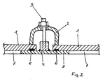
- Fig. 2 shows a section along line II-II in Fig. 1 , wherein here two openings 7 can be seen.
- the strip 4 is welded to the side wall 5 of the apparatus.
- the seal is a U-shaped profile 2, which is connected by means of bolts 3 with the bar 4 and presses both cover 1 to the side wall 5.
- a soft seal 6 inserted in the circumferential lid groove compensates for any existing surface inaccuracies and thus ensures hermetic sealing of the opening (s) 7.
- the voltage can be space-saving with a common U-shaped profile 2, which then equal high legs having. in contrast, the legs are unequal for bracing directly on the side wall 5, as well as in Fig. 3 (Section according to line III-III in Fig. 1 ).
- the strips 4 have the dual function of stiffening and bracing. They advantageously have a high, but at least square cross-section.
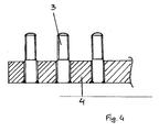
- the bolts 3 are inserted into the holes or screwed and welded from the back (see Fig. 4 ).
- the strips are now welded to the side wall after any necessary straightening work by simply creating fillet welds.
- the heat exchangers have as in Fig. 5 illustrated, advantageously at its outer end also a closure plate 1, as described above, on. Inlet and outlet of the coils 8 open into collector tubes located outside 9. The passages through the closure plate 1 are welded tight. At its inner end, the coils 8 are taken in a holding frame 10.
- This support frame 10 can be connected by (not shown) stiffening plates directly to the closure plate 1, resulting in a compact unit.
- the side wall 5 reinforced according to the invention is also unable to absorb the bending weight forces.
Landscapes
- Engineering & Computer Science (AREA)
- General Engineering & Computer Science (AREA)
- Mechanical Engineering (AREA)
- Physics & Mathematics (AREA)
- Thermal Sciences (AREA)
- Butt Welding And Welding Of Specific Article (AREA)
- Gasket Seals (AREA)
- Heat-Exchange Devices With Radiators And Conduit Assemblies (AREA)
Description
- Die Erfindung betrifft eine Vorrichtung zum hermetischen Verschließen von großen Öffnungen in Apparaten, die mit niedrigem inneren Überdruck beaufschlagt werden.
- Für die Abdichtung von Apparateöffnungen werden oblicherweise eingeschweißte, runde Flansche und passende Deckel mit Dichtungen verwendet. Damit sich die Dichtobertlächen nicht verziehen, müssen sie eine erhebliche Materialstärke aufweisen sowie mechanisch bearbeitet sein. Bei Druckbehältern auf mittlerem und hohem Drucknlveau Ist die hohe Materialstärke sowieso aus Festigkeitsgründen des Apparates erforderlich. Bei niedrigem Druckniveau und lufttechnischen Apparaten betragen die Wandstärken nur wenige Millimeter und bieten somit keine Gewähr für eine ausreichende Steifigkeit und Verzugsfreiheit der Dichtflächen, insbesondere bei großen, meist rechteckigen Öffnungsquerschnitten. Große Querschnitte sind beispielsweise erforderlich für Montage- und Zugangsöffnungen, oder für eingebaute Komponenten wie Rührer und Wärmetauscher. Eine Möglichkeit einer Abdichtung von Öffnungen bei niedrigen Drücken ist in der
DE 10 2006 018 557 A1 beschrieben. Hier wird ein Deckel mit Dichtleisten versehen, die in entsprechende Dichtleisten am Rahmen einer Öffnung in einem Gebäude angebracht sind, wodurch sich ein Schutz gegen Hochwasser ergibt Derartige Systeme sind aber für Behälter mit Innendruck nicht anwendbar. - Ziel der Erfindung ist es daher eine Vorrichtung zu schaffen, die bei niedrigen Drücken eine einfache, kostengünstige und hermetische Abdichtung gewährleistet.
- Die Erfindung ist daher dadurch gekennzeichnet, dass ein Verschlussdeckel (1) vorgesehen ist, der an der Außenseite durch ein U-förmiges Profil (2), das mittels Bolzen (3) mit einer Leiste (4) verbunden ist und den mindestens einen Verschlussdeckel (1) an die Seitenwand (5) des Apparates anpresst, wobei die Bolzen (3) In einer Leiste (4) montiert sind, die am Rand der Öffnung (7) des Apparates auf der Seltenwand (5) des Apparates montiert, insbesondere an die Seitenwand (5) angeschweißt, ist, wobei die Öffnung vorteilhafterweise rechteckig ausgeführt sein kann. Bei Einsatz der erfindungsgemäßen Vorrichtung können die konstruktiv vorgegebenen niedrigen Wandstärken beibehalten und trotzdem eine hermetische Abdichtung erreicht werden. Insbesondere kann auch auf eine aufwändige mechanische Bearbeitung der behälterseitigen Dichtfläche verzichtet werden. Dadurch ergibt sich eine wirtschaftlich vorteilhafte Ausführung des Apparates.
- Als besonders günstig hat sich erwiesen, wenn die Leiste mittels U-förmiger Profile auf die Seitenwand gepresst wird. Dadurch wird eine gleichmäßige Anpressung erreicht.
- Eine günstige Weiterbildung der Erfindung ist dadurch gekennzeichnet, dass der Verschlussdeckel eine Nut für eine Weichdichtung aufweist. Damit kann eine sehr gute hermetische Abdichtung erreicht werden.
- Werden mehrere Öffnungen mit Verschlussdeckeln vorgesehen, ist es besonders vorteilhaft, wenn eng nebeneinander liegende Verschlussdeckel von einem gemeinsamen Profil gespannt werden.
- Eine günstige Ausgestaltung der Erfindung ist dadurch gekennzeichnet, dass die Bolzen in die Leiste gesteckt oder geschraubt werden, wobei die Bolzen mit der Leiste verklebt oder verschweißt werden können.
- Die Erfindung erweist sich als besonderes vorteilhaft, wenn der Verschlussdeckel Teil eines Wärmetauscherpaketes ist, wobei das Wärmetauscherpaket mit Hilfe von Laufschienen und verstellbaren Aufhängerollen genau ausgerichtet werden kann, dass der Verschlussdeckel planparallel zur Seitenwand steht.
- Die Erfindung wird nun anhand der Zeichnungen beispielhaft beschrieben, wobei
-
Fig. 1 eine Ausführung der Erfindung, -
Fig. 2 einen Schnitt gemäß Linie II-II inFig. 1 , -
Fig. 3 einen Schnitt gemäß Linie III-III inFig. 1 , -
Fig. 4 einen Schnitt durch eine Leiste gemäß der Erfindung und -
Fig. 5 eine weitere Ausführungsform gemäß der Erfindung darstellt. -
Fig. 1 zeigt einen Verschlussdeckel 1, der mittels U-förmigen Profilen 2 über Bolzen 3, die mit einer Leiste 4 verschweißt sind, auf die Seitenwand 5 gespannt wird. Die Leisten 4 sind am Rand der Öffnungen 7 auf die Seitenwand geschweißt und verstärken dadurch den Dichtungsbereich der Seitenwand. Zusammen mit den U-förmigen Profilen 2 ergibt sich damit eine extrem steife Konstruktion für den Dichtungsbereich. -
Fig. 2 zeigt einen Schnitt gemäß Linie II-II inFig. 1 , wobei hier zwei Öffnungen 7 erkennbar sind. Die Leiste 4 ist an die Seitenwand 5 des Apparates geschweißt. Zur Dichtung dient ein U-förmiges Profil 2, das mittels Bolzen 3 mit der Leiste 4 verbunden ist und beide Verschlussdeckel 1 an die Seitenwand 5 anpresst. Eine in die umlaufende Deckelnut eingelegte Weichdichtung 6 gleicht noch vorhandene Oberflächenungenauigkeiten aus und sorgt so für eine hermetische Abdichtung der Öffnung(en) 7. Bei nebeneinander liegenden Öffnungen kann die Spannung platzsparend mit einem gemeinsamen U-förmigen Profil 2 erfolgen, welches dann gleich hohe Schenkel aufweist. im Gegensatz dazu sind die Schenkel zur Abspannung direkt auf die Seitenwand 5 ungleich, wie auch inFig. 3 (Schnitt gemäß Linie III-III inFig. 1 ) dargestellt. - Die Leisten 4 haben die Doppelfunktion Versteifung und Verspannung. Sie weisen vorteilhafterweise einen hohen, mindestens jedoch quadratischen Querschnitt auf. Die Bolzen 3 werden in die Löcher gesteckt oder geschraubt und von der Rückseite verschweißt (siehe
Fig. 4 ). Die Leisten werden nun nach ggf. erforderlicher Richtarbeit durch einfach zu erstellende Kehlnähte auf die Seitenwand geschweißt. - Wenn nicht nur lediglich Öffnungen 7 zu verschließen sind, sondern beispielsweise Wärmetauscherbündel seitlich in den Apparat geschoben werden, sind weitere Maßnahmen erforderlich. Die Wärmetauscher weisen wie in
Fig. 5 dargestellt, vorteilhafterweise an ihrem äußeren Ende ebenfalls eine Verschlussplatte 1, wie zuvor beschrieben, auf. Ein- und Auslauf der Rohrschlangen 8 münden in außen gelegene Sammlerrohre 9. Die Durchtritte durch die Verschlussplatte 1 sind dichtgeschweißt. An ihrem inneren Ende sind die Rohrschlangen 8 in einem Halterahmen 10 gefasst. Dieser Halterahmen 10 kann durch (nicht dargestellte) Aussteifungsbleche direkt mit der Verschlussplatte 1 verbunden werden, wodurch sich eine kompakte Einheit ergibt. Bei großen Einschubtiefen ist jedoch auch die erfindungsgemäß verstärkte Seitenwand 5 nicht in der Lage, die biegenden Gewichtskräfte abzufangen. Zur Abhilfe werden die sich gegenüberliegenden Seitenwände mit Laufschienen 12 verbunden, wodurch sich alleine schon eine Verstärkung ergibt. Darüber hinaus wird der Halterahmen 10 des Wärmetauschers über einstellbare Laufrollen 11 an den Laufschienen 12 abgehängt. Nach dem Einschieben des Wärmetauscherpakets in den Apparat kann so die Verschlussplatte 1 planparallel zur Seitenwand 5 ausgerichtet werden und wird damit keinen zusätzlichen, Undichtigkeit verursachenden Biegemomenten ausgesetzt. Die Befestigung und Abdichtung der Verschlussplatte erfolgt wie zuvor beschrieben mittels erfindungsgemäßen U-förmigen Profilen 2 und Bolzenleisten 4.
Claims (8)
- Vorrichtung zum hermetischen Verschließen von großen Öffnungen in Apparaten, die mit niedrigem inneren Überdruck beaufschlagt werden, dadurch gekennzeichnet, dass mindestens ein Verschlussdeckel (1) vorgesehen ist, der an der Außenseite durch ein U-förmiges Profil (2), das mittels Bolzen (3) mit einer Leiste (4) verbunden ist und den mindestens einen Verschlussdeckel (1) an die Seitenwand (5) des Apparates anpresst, wobei die Bolzen (3) in einer Leiste (4) montiert sind, die am Rand der Öffnung (7) des Apparates auf der Seitenwand (5) des Apparates montiert, insbesondere an die Seitenwand (5) angeschweißt, ist.
- Vorrichtung nach Anspruch 1, dadurch gekennzeichnet, dass die Öffnungen (7) rechteckig ausgeführt sind.
- Vorrichtung nach einem der Ansprüche 1 oder 2, dadurch gekennzeichnet, dass der Verschlussdeckel (1) eine Nut für eine Weichdichtung (6) aufweist.
- Vorrichtung nach einem der Ansprüche 1 bis 3, dadurch gekennzeichnet, dass mehrere Öffnungen (7) mit Verschlussdeckeln (1) vorgesehen sind, wobei eng nebeneinander liegende Verschlussdeckel (1) von einem gemeinsamen Profil (2) gespannt werden.
- Vorrichtung nach einem der Ansprüche 1 bis 4, dadurch gekennzeichnet, dass die Bolzen (3) in die Leiste (4) gesteckt oder geschraubt werden.
- Vorrichtung nach Anspruch 5, dadurch gekennzeichnet, dass die Bolzen (3) mit der Leiste (4) verklebt oder verschweißt werden.
- Vorrichtung nach einem der Ansprüche 1 bis 6, dadurch gekennzeichnet, dass der Verschlussdeckel (1) Teil eines Wärmetauscherpaketes ist.
- Vorrichtung nach Anspruch 7, dadurch gekennzeichnet, dass das Wärmetauscherpaket mit Hilfe von Laufschienen (12) und verstellbaren Aufhängerollen (11) genau ausgerichtet werden kann, so dass der Verschlussdeckel (1) planparallel zur Seitenwand (5) steht.
Priority Applications (1)
| Application Number | Priority Date | Filing Date | Title |
|---|---|---|---|
| PL11717451T PL2567034T3 (pl) | 2010-05-03 | 2011-03-25 | Urządzenie do hermetycznego zamykania dużych otworów w aparatach |
Applications Claiming Priority (2)
| Application Number | Priority Date | Filing Date | Title |
|---|---|---|---|
| AT0074210A AT509210B1 (de) | 2010-05-03 | 2010-05-03 | Vorrichtung zum hermetischen verschliessen von grossen öffnungen in apparaten |
| PCT/AT2011/000149 WO2011137468A1 (de) | 2010-05-03 | 2011-03-25 | VORRICHTUNG ZUM HERMETISCHEN VERSCHLIEßEN VON GROßEN ÖFFNUNGEN IN APPARATEN |
Publications (2)
| Publication Number | Publication Date |
|---|---|
| EP2567034A1 EP2567034A1 (de) | 2013-03-13 |
| EP2567034B1 true EP2567034B1 (de) | 2015-08-19 |
Family
ID=44170055
Family Applications (1)
| Application Number | Title | Priority Date | Filing Date |
|---|---|---|---|
| EP11717451.6A Not-in-force EP2567034B1 (de) | 2010-05-03 | 2011-03-25 | VORRICHTUNG ZUM HERMETISCHEN VERSCHLIEßEN VON GROßEN ÖFFNUNGEN IN APPARATEN |
Country Status (6)
| Country | Link |
|---|---|
| US (1) | US9976651B2 (de) |
| EP (1) | EP2567034B1 (de) |
| AT (1) | AT509210B1 (de) |
| PL (1) | PL2567034T3 (de) |
| TW (1) | TWI537502B (de) |
| WO (1) | WO2011137468A1 (de) |
Families Citing this family (3)
| Publication number | Priority date | Publication date | Assignee | Title |
|---|---|---|---|---|
| ES2423967B1 (es) * | 2012-03-13 | 2014-11-14 | Manufactura Moderna De Metales S.A. | Junta portadora de tornillos |
| CN107310839B (zh) * | 2017-08-08 | 2023-03-21 | 成都大学 | 一种充气自锁式包装盒 |
| CN112664819B (zh) * | 2020-12-04 | 2022-09-27 | 广州东部发展燃气有限公司 | 密封开关装置及燃气过滤器 |
Family Cites Families (12)
| Publication number | Priority date | Publication date | Assignee | Title |
|---|---|---|---|---|
| US3018127A (en) * | 1958-10-30 | 1962-01-23 | Westinghouse Electric Corp | Enclosed device with cover-mounting means |
| NL7308591A (de) * | 1973-06-20 | 1974-12-24 | ||
| FR2286251A2 (fr) * | 1974-09-26 | 1976-04-23 | Irba Gp | Procede d'incorporation de menuiseries en profiles legers dans les panneaux prefabriques lourds |
| FR2593567B1 (fr) * | 1986-01-29 | 1990-09-14 | Jacomex Sa | Structure de raccordement demontable et elastique des parois d'une enceinte etanche |
| DE3743789A1 (de) * | 1987-12-23 | 1989-07-06 | Buehler Miag Gmbh | Abschlussdeckel fuer luft- und gasfilter |
| US5110369A (en) * | 1990-10-24 | 1992-05-05 | Mobil Solar Energy Corporation | Cable interconnections for solar cell modules |
| US5348267A (en) * | 1992-09-18 | 1994-09-20 | Eaton Corporation | Apparatus for isolating a sensor |
| JPH09188347A (ja) * | 1995-12-31 | 1997-07-22 | Narimoto Container Kk | 金属製液体コンテナーのマンホール蓋締付装置 |
| JP2001262844A (ja) * | 2000-03-16 | 2001-09-26 | Sankyu Inc | 構造物補強装置 |
| US6735912B2 (en) * | 2001-10-30 | 2004-05-18 | Steve Riggio | Method and apparatus of weather sealing adjacently jointed building panels |
| DE102006018557A1 (de) * | 2006-04-21 | 2007-10-25 | Andreas Schwaiger | Multifunktionssystem gegen Hochwasser |
| US8602245B2 (en) * | 2010-01-05 | 2013-12-10 | Cooper Technologies Company | Enclosure clamps and clamp systems |
-
2010
- 2010-05-03 AT AT0074210A patent/AT509210B1/de not_active IP Right Cessation
-
2011
- 2011-03-25 US US13/695,992 patent/US9976651B2/en not_active Expired - Fee Related
- 2011-03-25 WO PCT/AT2011/000149 patent/WO2011137468A1/de not_active Ceased
- 2011-03-25 PL PL11717451T patent/PL2567034T3/pl unknown
- 2011-03-25 EP EP11717451.6A patent/EP2567034B1/de not_active Not-in-force
- 2011-04-15 TW TW100113259A patent/TWI537502B/zh not_active IP Right Cessation
Also Published As
| Publication number | Publication date |
|---|---|
| PL2567034T3 (pl) | 2016-01-29 |
| US20130228981A1 (en) | 2013-09-05 |
| TW201200765A (en) | 2012-01-01 |
| EP2567034A1 (de) | 2013-03-13 |
| AT509210A4 (de) | 2011-07-15 |
| US9976651B2 (en) | 2018-05-22 |
| AT509210B1 (de) | 2011-07-15 |
| TWI537502B (zh) | 2016-06-11 |
| WO2011137468A1 (de) | 2011-11-10 |
Similar Documents
| Publication | Publication Date | Title |
|---|---|---|
| DE102018211473B3 (de) | Batteriegehäuse | |
| WO2016008844A1 (de) | Vakuumanlage, insbesondere plasmaanlage, mit einem rundum geschlossenen kammerstrangpressprofil | |
| DE10221061A1 (de) | Membran, Membranplatte und Kammerplatte für eIne Filterpresse | |
| DE3141161A1 (de) | Plattenwaermeaustauscher | |
| AT509210B1 (de) | Vorrichtung zum hermetischen verschliessen von grossen öffnungen in apparaten | |
| DE595190C (de) | Vorrichtung mit spiralfoermig im Abstand voneinander gewundenen Blechen zur Waermeuebertragung | |
| DE9306878U1 (de) | Transportvorrichtung für Kunstgegenstände | |
| DE958671C (de) | Dichte Durchfuehrung fuer Leitungsbuendel durch eine Wand | |
| EP2423629B1 (de) | Plattenwärmetauscher in gedichteter Ausführung | |
| DE2831998A1 (de) | Isoliertuervorrichtung | |
| DE2437261A1 (de) | Doppelwandige metalltuer in verbundbauweise | |
| DE2939070C2 (de) | Koksofentür | |
| EP3745548A1 (de) | Gasisolierter behälter | |
| DE1250217B (de) | Vorrichtung zum Abdichten des losnehmbaren Verschlußgliedes von Druckbehältern Rohrleitun gen oder Armaturen | |
| DE4230287C2 (de) | Kessel für elektrische Bauteile | |
| DE202010001711U1 (de) | Flächiger feuerfester Abschluss | |
| DE102004015462B4 (de) | Mehrteilige Gießform für den Druckguss von keramischen Formkörpern, deren Verwendung sowie Verfahren mit einer solchen Gießform | |
| DE102013227094A1 (de) | Plattenwärmetauscher | |
| EP3724555A2 (de) | Lüftungsgerät und verfahren zum warten eines lüftungsgerätes und zugehörige verkeileinheit | |
| DE202009006127U1 (de) | Eckwinkel für eine Flanschverbindung von Klimatisierungskanälen | |
| EP2553297B1 (de) | Verschliessbarer behälter | |
| DE10110162B4 (de) | Umformwerkzeug zum hydromechanischen Tiefziehen von Werkstücken aus Blechzuschnitten | |
| DE2013420A1 (de) | Vorrichtung zum Anpressen von Ab Sperrplatten in Absperrorganen in ihrer Absperrstellung | |
| DE102022214327A1 (de) | Elektrolyseur | |
| EP3798580A1 (de) | Verfahren zur herstellung eines messkopfgehäuses, deckel und messkopfgehäuse |
Legal Events
| Date | Code | Title | Description |
|---|---|---|---|
| PUAI | Public reference made under article 153(3) epc to a published international application that has entered the european phase |
Free format text: ORIGINAL CODE: 0009012 |
|
| 17P | Request for examination filed |
Effective date: 20121022 |
|
| AK | Designated contracting states |
Kind code of ref document: A1 Designated state(s): AL AT BE BG CH CY CZ DE DK EE ES FI FR GB GR HR HU IE IS IT LI LT LU LV MC MK MT NL NO PL PT RO RS SE SI SK SM TR |
|
| DAX | Request for extension of the european patent (deleted) | ||
| REG | Reference to a national code |
Ref country code: DE Ref legal event code: R079 Ref document number: 502011007640 Country of ref document: DE Free format text: PREVIOUS MAIN CLASS: E04B0001210000 Ipc: F28F0009013000 |
|
| RIC1 | Information provided on ipc code assigned before grant |
Ipc: F28F 9/00 20060101ALI20131018BHEP Ipc: F28F 9/013 20060101AFI20131018BHEP Ipc: F16J 15/06 20060101ALI20131018BHEP |
|
| GRAP | Despatch of communication of intention to grant a patent |
Free format text: ORIGINAL CODE: EPIDOSNIGR1 |
|
| INTG | Intention to grant announced |
Effective date: 20140227 |
|
| GRAS | Grant fee paid |
Free format text: ORIGINAL CODE: EPIDOSNIGR3 |
|
| GRAP | Despatch of communication of intention to grant a patent |
Free format text: ORIGINAL CODE: EPIDOSNIGR1 |
|
| INTG | Intention to grant announced |
Effective date: 20150401 |
|
| GRAA | (expected) grant |
Free format text: ORIGINAL CODE: 0009210 |
|
| AK | Designated contracting states |
Kind code of ref document: B1 Designated state(s): AL AT BE BG CH CY CZ DE DK EE ES FI FR GB GR HR HU IE IS IT LI LT LU LV MC MK MT NL NO PL PT RO RS SE SI SK SM TR |
|
| REG | Reference to a national code |
Ref country code: GB Ref legal event code: FG4D Free format text: NOT ENGLISH |
|
| REG | Reference to a national code |
Ref country code: CH Ref legal event code: EP |
|
| REG | Reference to a national code |
Ref country code: IE Ref legal event code: FG4D Free format text: LANGUAGE OF EP DOCUMENT: GERMAN |
|
| REG | Reference to a national code |
Ref country code: AT Ref legal event code: REF Ref document number: 744105 Country of ref document: AT Kind code of ref document: T Effective date: 20150915 |
|
| REG | Reference to a national code |
Ref country code: DE Ref legal event code: R096 Ref document number: 502011007640 Country of ref document: DE |
|
| REG | Reference to a national code |
Ref country code: LT Ref legal event code: MG4D |
|
| REG | Reference to a national code |
Ref country code: NL Ref legal event code: FP |
|
| PG25 | Lapsed in a contracting state [announced via postgrant information from national office to epo] |
Ref country code: GR Free format text: LAPSE BECAUSE OF FAILURE TO SUBMIT A TRANSLATION OF THE DESCRIPTION OR TO PAY THE FEE WITHIN THE PRESCRIBED TIME-LIMIT Effective date: 20151120 Ref country code: LV Free format text: LAPSE BECAUSE OF FAILURE TO SUBMIT A TRANSLATION OF THE DESCRIPTION OR TO PAY THE FEE WITHIN THE PRESCRIBED TIME-LIMIT Effective date: 20150819 Ref country code: FI Free format text: LAPSE BECAUSE OF FAILURE TO SUBMIT A TRANSLATION OF THE DESCRIPTION OR TO PAY THE FEE WITHIN THE PRESCRIBED TIME-LIMIT Effective date: 20150819 Ref country code: NO Free format text: LAPSE BECAUSE OF FAILURE TO SUBMIT A TRANSLATION OF THE DESCRIPTION OR TO PAY THE FEE WITHIN THE PRESCRIBED TIME-LIMIT Effective date: 20151119 Ref country code: LT Free format text: LAPSE BECAUSE OF FAILURE TO SUBMIT A TRANSLATION OF THE DESCRIPTION OR TO PAY THE FEE WITHIN THE PRESCRIBED TIME-LIMIT Effective date: 20150819 |
|
| PG25 | Lapsed in a contracting state [announced via postgrant information from national office to epo] |
Ref country code: IS Free format text: LAPSE BECAUSE OF FAILURE TO SUBMIT A TRANSLATION OF THE DESCRIPTION OR TO PAY THE FEE WITHIN THE PRESCRIBED TIME-LIMIT Effective date: 20151219 Ref country code: RS Free format text: LAPSE BECAUSE OF FAILURE TO SUBMIT A TRANSLATION OF THE DESCRIPTION OR TO PAY THE FEE WITHIN THE PRESCRIBED TIME-LIMIT Effective date: 20150819 Ref country code: PT Free format text: LAPSE BECAUSE OF FAILURE TO SUBMIT A TRANSLATION OF THE DESCRIPTION OR TO PAY THE FEE WITHIN THE PRESCRIBED TIME-LIMIT Effective date: 20151221 Ref country code: ES Free format text: LAPSE BECAUSE OF FAILURE TO SUBMIT A TRANSLATION OF THE DESCRIPTION OR TO PAY THE FEE WITHIN THE PRESCRIBED TIME-LIMIT Effective date: 20150819 Ref country code: SE Free format text: LAPSE BECAUSE OF FAILURE TO SUBMIT A TRANSLATION OF THE DESCRIPTION OR TO PAY THE FEE WITHIN THE PRESCRIBED TIME-LIMIT Effective date: 20150819 |
|
| REG | Reference to a national code |
Ref country code: FR Ref legal event code: PLFP Year of fee payment: 6 |
|
| REG | Reference to a national code |
Ref country code: SK Ref legal event code: T3 Ref document number: E 19749 Country of ref document: SK |
|
| PG25 | Lapsed in a contracting state [announced via postgrant information from national office to epo] |
Ref country code: EE Free format text: LAPSE BECAUSE OF FAILURE TO SUBMIT A TRANSLATION OF THE DESCRIPTION OR TO PAY THE FEE WITHIN THE PRESCRIBED TIME-LIMIT Effective date: 20150819 Ref country code: DK Free format text: LAPSE BECAUSE OF FAILURE TO SUBMIT A TRANSLATION OF THE DESCRIPTION OR TO PAY THE FEE WITHIN THE PRESCRIBED TIME-LIMIT Effective date: 20150819 |
|
| REG | Reference to a national code |
Ref country code: DE Ref legal event code: R097 Ref document number: 502011007640 Country of ref document: DE |
|
| PG25 | Lapsed in a contracting state [announced via postgrant information from national office to epo] |
Ref country code: RO Free format text: LAPSE BECAUSE OF FAILURE TO SUBMIT A TRANSLATION OF THE DESCRIPTION OR TO PAY THE FEE WITHIN THE PRESCRIBED TIME-LIMIT Effective date: 20150819 |
|
| PLBE | No opposition filed within time limit |
Free format text: ORIGINAL CODE: 0009261 |
|
| STAA | Information on the status of an ep patent application or granted ep patent |
Free format text: STATUS: NO OPPOSITION FILED WITHIN TIME LIMIT |
|
| 26N | No opposition filed |
Effective date: 20160520 |
|
| PG25 | Lapsed in a contracting state [announced via postgrant information from national office to epo] |
Ref country code: SI Free format text: LAPSE BECAUSE OF FAILURE TO SUBMIT A TRANSLATION OF THE DESCRIPTION OR TO PAY THE FEE WITHIN THE PRESCRIBED TIME-LIMIT Effective date: 20150819 |
|
| PG25 | Lapsed in a contracting state [announced via postgrant information from national office to epo] |
Ref country code: LU Free format text: LAPSE BECAUSE OF FAILURE TO SUBMIT A TRANSLATION OF THE DESCRIPTION OR TO PAY THE FEE WITHIN THE PRESCRIBED TIME-LIMIT Effective date: 20160325 Ref country code: MC Free format text: LAPSE BECAUSE OF FAILURE TO SUBMIT A TRANSLATION OF THE DESCRIPTION OR TO PAY THE FEE WITHIN THE PRESCRIBED TIME-LIMIT Effective date: 20150819 |
|
| REG | Reference to a national code |
Ref country code: CH Ref legal event code: PL |
|
| REG | Reference to a national code |
Ref country code: IE Ref legal event code: MM4A |
|
| PG25 | Lapsed in a contracting state [announced via postgrant information from national office to epo] |
Ref country code: LI Free format text: LAPSE BECAUSE OF NON-PAYMENT OF DUE FEES Effective date: 20160331 Ref country code: IE Free format text: LAPSE BECAUSE OF NON-PAYMENT OF DUE FEES Effective date: 20160325 Ref country code: CH Free format text: LAPSE BECAUSE OF NON-PAYMENT OF DUE FEES Effective date: 20160331 |
|
| REG | Reference to a national code |
Ref country code: FR Ref legal event code: PLFP Year of fee payment: 7 |
|
| REG | Reference to a national code |
Ref country code: AT Ref legal event code: MM01 Ref document number: 744105 Country of ref document: AT Kind code of ref document: T Effective date: 20160325 |
|
| PG25 | Lapsed in a contracting state [announced via postgrant information from national office to epo] |
Ref country code: AT Free format text: LAPSE BECAUSE OF NON-PAYMENT OF DUE FEES Effective date: 20160325 Ref country code: MT Free format text: LAPSE BECAUSE OF FAILURE TO SUBMIT A TRANSLATION OF THE DESCRIPTION OR TO PAY THE FEE WITHIN THE PRESCRIBED TIME-LIMIT Effective date: 20150819 |
|
| REG | Reference to a national code |
Ref country code: FR Ref legal event code: PLFP Year of fee payment: 8 |
|
| PG25 | Lapsed in a contracting state [announced via postgrant information from national office to epo] |
Ref country code: SM Free format text: LAPSE BECAUSE OF FAILURE TO SUBMIT A TRANSLATION OF THE DESCRIPTION OR TO PAY THE FEE WITHIN THE PRESCRIBED TIME-LIMIT Effective date: 20150819 Ref country code: CY Free format text: LAPSE BECAUSE OF FAILURE TO SUBMIT A TRANSLATION OF THE DESCRIPTION OR TO PAY THE FEE WITHIN THE PRESCRIBED TIME-LIMIT Effective date: 20150819 Ref country code: HU Free format text: LAPSE BECAUSE OF FAILURE TO SUBMIT A TRANSLATION OF THE DESCRIPTION OR TO PAY THE FEE WITHIN THE PRESCRIBED TIME-LIMIT; INVALID AB INITIO Effective date: 20110325 |
|
| PG25 | Lapsed in a contracting state [announced via postgrant information from national office to epo] |
Ref country code: HR Free format text: LAPSE BECAUSE OF FAILURE TO SUBMIT A TRANSLATION OF THE DESCRIPTION OR TO PAY THE FEE WITHIN THE PRESCRIBED TIME-LIMIT Effective date: 20150819 Ref country code: MK Free format text: LAPSE BECAUSE OF FAILURE TO SUBMIT A TRANSLATION OF THE DESCRIPTION OR TO PAY THE FEE WITHIN THE PRESCRIBED TIME-LIMIT Effective date: 20150819 |
|
| PG25 | Lapsed in a contracting state [announced via postgrant information from national office to epo] |
Ref country code: BG Free format text: LAPSE BECAUSE OF FAILURE TO SUBMIT A TRANSLATION OF THE DESCRIPTION OR TO PAY THE FEE WITHIN THE PRESCRIBED TIME-LIMIT Effective date: 20150819 |
|
| PG25 | Lapsed in a contracting state [announced via postgrant information from national office to epo] |
Ref country code: AL Free format text: LAPSE BECAUSE OF FAILURE TO SUBMIT A TRANSLATION OF THE DESCRIPTION OR TO PAY THE FEE WITHIN THE PRESCRIBED TIME-LIMIT Effective date: 20150819 |
|
| PGFP | Annual fee paid to national office [announced via postgrant information from national office to epo] |
Ref country code: GB Payment date: 20190320 Year of fee payment: 9 Ref country code: FR Payment date: 20190322 Year of fee payment: 9 Ref country code: CZ Payment date: 20190226 Year of fee payment: 9 Ref country code: IT Payment date: 20190325 Year of fee payment: 9 Ref country code: PL Payment date: 20190226 Year of fee payment: 9 Ref country code: DE Payment date: 20190321 Year of fee payment: 9 |
|
| PGFP | Annual fee paid to national office [announced via postgrant information from national office to epo] |
Ref country code: BE Payment date: 20190320 Year of fee payment: 9 Ref country code: TR Payment date: 20190321 Year of fee payment: 9 Ref country code: NL Payment date: 20190320 Year of fee payment: 9 |
|
| PGFP | Annual fee paid to national office [announced via postgrant information from national office to epo] |
Ref country code: SK Payment date: 20190227 Year of fee payment: 9 |
|
| REG | Reference to a national code |
Ref country code: DE Ref legal event code: R119 Ref document number: 502011007640 Country of ref document: DE |
|
| PG25 | Lapsed in a contracting state [announced via postgrant information from national office to epo] |
Ref country code: CZ Free format text: LAPSE BECAUSE OF NON-PAYMENT OF DUE FEES Effective date: 20200325 |
|
| REG | Reference to a national code |
Ref country code: NL Ref legal event code: MM Effective date: 20200401 |
|
| REG | Reference to a national code |
Ref country code: SK Ref legal event code: MM4A Ref document number: E 19749 Country of ref document: SK Effective date: 20200325 |
|
| REG | Reference to a national code |
Ref country code: BE Ref legal event code: MM Effective date: 20200331 |
|
| PG25 | Lapsed in a contracting state [announced via postgrant information from national office to epo] |
Ref country code: NL Free format text: LAPSE BECAUSE OF NON-PAYMENT OF DUE FEES Effective date: 20200401 |
|
| PG25 | Lapsed in a contracting state [announced via postgrant information from national office to epo] |
Ref country code: FR Free format text: LAPSE BECAUSE OF NON-PAYMENT OF DUE FEES Effective date: 20200331 Ref country code: DE Free format text: LAPSE BECAUSE OF NON-PAYMENT OF DUE FEES Effective date: 20201001 |
|
| PG25 | Lapsed in a contracting state [announced via postgrant information from national office to epo] |
Ref country code: BE Free format text: LAPSE BECAUSE OF NON-PAYMENT OF DUE FEES Effective date: 20200331 Ref country code: SK Free format text: LAPSE BECAUSE OF NON-PAYMENT OF DUE FEES Effective date: 20200325 |
|
| GBPC | Gb: european patent ceased through non-payment of renewal fee |
Effective date: 20200325 |
|
| PG25 | Lapsed in a contracting state [announced via postgrant information from national office to epo] |
Ref country code: GB Free format text: LAPSE BECAUSE OF NON-PAYMENT OF DUE FEES Effective date: 20200325 |
|
| PG25 | Lapsed in a contracting state [announced via postgrant information from national office to epo] |
Ref country code: IT Free format text: LAPSE BECAUSE OF NON-PAYMENT OF DUE FEES Effective date: 20200325 |
|
| PG25 | Lapsed in a contracting state [announced via postgrant information from national office to epo] |
Ref country code: PL Free format text: LAPSE BECAUSE OF NON-PAYMENT OF DUE FEES Effective date: 20200325 |
|
| PG25 | Lapsed in a contracting state [announced via postgrant information from national office to epo] |
Ref country code: TR Free format text: LAPSE BECAUSE OF NON-PAYMENT OF DUE FEES Effective date: 20200325 |