EP2565689A1 - Lichtwellenleiter für optische Einheit - Google Patents
Lichtwellenleiter für optische Einheit Download PDFInfo
- Publication number
- EP2565689A1 EP2565689A1 EP12177701A EP12177701A EP2565689A1 EP 2565689 A1 EP2565689 A1 EP 2565689A1 EP 12177701 A EP12177701 A EP 12177701A EP 12177701 A EP12177701 A EP 12177701A EP 2565689 A1 EP2565689 A1 EP 2565689A1
- Authority
- EP
- European Patent Office
- Prior art keywords
- guide
- branches
- light
- intersection
- optical unit
- Prior art date
- Legal status (The legal status is an assumption and is not a legal conclusion. Google has not performed a legal analysis and makes no representation as to the accuracy of the status listed.)
- Granted
Links
- 230000003287 optical effect Effects 0.000 title claims description 30
- 230000006870 function Effects 0.000 claims description 27
- 238000011144 upstream manufacturing Methods 0.000 claims description 17
- 230000009131 signaling function Effects 0.000 claims description 8
- 238000009792 diffusion process Methods 0.000 abstract description 6
- 235000021183 entrée Nutrition 0.000 description 5
- 239000000463 material Substances 0.000 description 3
- 230000005540 biological transmission Effects 0.000 description 2
- 239000011248 coating agent Substances 0.000 description 2
- 238000000576 coating method Methods 0.000 description 2
- 229940082150 encore Drugs 0.000 description 2
- 230000004907 flux Effects 0.000 description 2
- 238000004519 manufacturing process Methods 0.000 description 2
- 229920003229 poly(methyl methacrylate) Polymers 0.000 description 2
- 239000004926 polymethyl methacrylate Substances 0.000 description 2
- 230000011664 signaling Effects 0.000 description 2
- 230000000007 visual effect Effects 0.000 description 2
- 230000015572 biosynthetic process Effects 0.000 description 1
- 238000009795 derivation Methods 0.000 description 1
- 238000000034 method Methods 0.000 description 1
- 238000000465 moulding Methods 0.000 description 1
- 239000004417 polycarbonate Substances 0.000 description 1
- 229920000515 polycarbonate Polymers 0.000 description 1
- 239000012780 transparent material Substances 0.000 description 1
Images


Classifications
-
- G—PHYSICS
- G02—OPTICS
- G02B—OPTICAL ELEMENTS, SYSTEMS OR APPARATUS
- G02B6/00—Light guides; Structural details of arrangements comprising light guides and other optical elements, e.g. couplings
- G02B6/0001—Light guides; Structural details of arrangements comprising light guides and other optical elements, e.g. couplings specially adapted for lighting devices or systems
- G02B6/0005—Light guides; Structural details of arrangements comprising light guides and other optical elements, e.g. couplings specially adapted for lighting devices or systems the light guides being of the fibre type
- G02B6/001—Light guides; Structural details of arrangements comprising light guides and other optical elements, e.g. couplings specially adapted for lighting devices or systems the light guides being of the fibre type the light being emitted along at least a portion of the lateral surface of the fibre
-
- F—MECHANICAL ENGINEERING; LIGHTING; HEATING; WEAPONS; BLASTING
- F21—LIGHTING
- F21S—NON-PORTABLE LIGHTING DEVICES; SYSTEMS THEREOF; VEHICLE LIGHTING DEVICES SPECIALLY ADAPTED FOR VEHICLE EXTERIORS
- F21S41/00—Illuminating devices specially adapted for vehicle exteriors, e.g. headlamps
- F21S41/20—Illuminating devices specially adapted for vehicle exteriors, e.g. headlamps characterised by refractors, transparent cover plates, light guides or filters
- F21S41/24—Light guides
-
- F—MECHANICAL ENGINEERING; LIGHTING; HEATING; WEAPONS; BLASTING
- F21—LIGHTING
- F21S—NON-PORTABLE LIGHTING DEVICES; SYSTEMS THEREOF; VEHICLE LIGHTING DEVICES SPECIALLY ADAPTED FOR VEHICLE EXTERIORS
- F21S43/00—Signalling devices specially adapted for vehicle exteriors, e.g. brake lamps, direction indicator lights or reversing lights
- F21S43/20—Signalling devices specially adapted for vehicle exteriors, e.g. brake lamps, direction indicator lights or reversing lights characterised by refractors, transparent cover plates, light guides or filters
- F21S43/235—Light guides
- F21S43/236—Light guides characterised by the shape of the light guide
- F21S43/237—Light guides characterised by the shape of the light guide rod-shaped
-
- F—MECHANICAL ENGINEERING; LIGHTING; HEATING; WEAPONS; BLASTING
- F21—LIGHTING
- F21S—NON-PORTABLE LIGHTING DEVICES; SYSTEMS THEREOF; VEHICLE LIGHTING DEVICES SPECIALLY ADAPTED FOR VEHICLE EXTERIORS
- F21S43/00—Signalling devices specially adapted for vehicle exteriors, e.g. brake lamps, direction indicator lights or reversing lights
- F21S43/20—Signalling devices specially adapted for vehicle exteriors, e.g. brake lamps, direction indicator lights or reversing lights characterised by refractors, transparent cover plates, light guides or filters
- F21S43/235—Light guides
- F21S43/236—Light guides characterised by the shape of the light guide
- F21S43/241—Light guides characterised by the shape of the light guide of complex shape
-
- F—MECHANICAL ENGINEERING; LIGHTING; HEATING; WEAPONS; BLASTING
- F21—LIGHTING
- F21S—NON-PORTABLE LIGHTING DEVICES; SYSTEMS THEREOF; VEHICLE LIGHTING DEVICES SPECIALLY ADAPTED FOR VEHICLE EXTERIORS
- F21S43/00—Signalling devices specially adapted for vehicle exteriors, e.g. brake lamps, direction indicator lights or reversing lights
- F21S43/20—Signalling devices specially adapted for vehicle exteriors, e.g. brake lamps, direction indicator lights or reversing lights characterised by refractors, transparent cover plates, light guides or filters
- F21S43/235—Light guides
- F21S43/242—Light guides characterised by the emission area
- F21S43/245—Light guides characterised by the emission area emitting light from one or more of its major surfaces
-
- F—MECHANICAL ENGINEERING; LIGHTING; HEATING; WEAPONS; BLASTING
- F21—LIGHTING
- F21S—NON-PORTABLE LIGHTING DEVICES; SYSTEMS THEREOF; VEHICLE LIGHTING DEVICES SPECIALLY ADAPTED FOR VEHICLE EXTERIORS
- F21S43/00—Signalling devices specially adapted for vehicle exteriors, e.g. brake lamps, direction indicator lights or reversing lights
- F21S43/20—Signalling devices specially adapted for vehicle exteriors, e.g. brake lamps, direction indicator lights or reversing lights characterised by refractors, transparent cover plates, light guides or filters
- F21S43/235—Light guides
- F21S43/249—Light guides with two or more light sources being coupled into the light guide
Definitions
- the present invention relates to a light guide. It relates more particularly to a light guide configured to be integrated in an optical unit capable of performing a signaling function or a lighting function or an interior lighting function for a motor vehicle.
- Inner lighting in particular, is understood to mean the lighting of the interior of a passenger compartment of a motor vehicle.
- the invention receives for particularly advantageous application the optical units performing a function of position lights, daytime running lights usually designated by the acronym DRL for Daytime Running Light or a direction indicator function.
- the present invention aims to provide a solution to the limitations of the prior art.
- a light guide configured to be integrated in an optical unit capable of carrying out a signaling function or a lighting function or an interior lighting function for a motor vehicle
- the guide comprising a light guide plurality of branches within which the light is guided at least in part, the guide comprising at least one intersection formed by at least four branches.
- the guide is used to diffuse light to form a light pattern that can have very varied shapes being very visible and easily recognizable.
- intersection is defined by at least two upstream branches disposed upstream of the intersection and at least two downstream branches disposed downstream of the intersection, the upstream and the downstream being defined with respect to the direction of propagation of the intersection. light in the guide.
- the guide includes a plurality of intersections formed of at least four branches.
- the branches and the intersections each have an outer envelope and the guide is shaped so that at least 70% of the light entering the guide escapes through the outer envelopes of the branches and / or intersections. More specifically, each branch has two ends separated by a longitudinal portion and a significant portion of the light entering the guide escapes through the outer envelope of the longitudinal portion. Preferably, an equally significant portion of the light entering the guide escapes through the outer envelope of the intersection.
- the guide is shaped so that all of the light entering the guide escapes through the outer shells of the branches and intersections.
- the guide has an outer envelope and arranged so that at least 80% of its outer envelope diffuses light.
- at least 80% of the surface visible from the outside is illuminated directly.
- the light is diffused out of the guide over the entire surface of the guide. The guide therefore does not include a portion by which the light does not escape.
- the light escapes out of the guide by diffusion.
- the guide comprises on its outer or inner envelope means for diffusing light.
- the light diffusion means are diffusion foci made in the surface of the guide by taking material. For example, laser impacts are made on the internal surface of the guide to form microprisms.
- At least two upstream branches of an intersection form between them an angle of less than 60 degrees and preferably less than 40 degrees.
- the guide comprises a plurality of intersections.
- the plurality of intersections and branches forms a mesh.
- the guide comprises at least one monolithic piece comprising several branches.
- the guide is formed of a single piece monolithic.
- all the branches are contained in a plane. They are therefore all in two dimensions. They can be curved or rectilinear. Their combination can make it possible to form a guide in two dimensions or in three dimensions. For this second embodiment, the intersections are shaped so that the different branches are not all in the same plane.
- At least one branch is in three dimensions.
- the branch is not contained in a plan.
- This type of guide has the advantage of being more visible and more easily recognizable.
- all the branches of the guide are in three dimensions.
- all the branches of the guide comprise at least one intersection.
- At least some of the branches have at least one curvature, the radii of curvature being greater than 150 millimeters (mm) for a guide section of less than 200 MM 2 .
- the branch section is between 100mm 2 and 250mm 2 . This section allows good light guidance and good visibility of the branches through which light is diffused.
- Another aspect of the invention relates to an optical unit adapted to perform a signaling function or a lighting function or an interior lighting function for a motor vehicle, comprising a guide according to any one of the preceding characteristics and comprising at least a source of light.
- the light source is a light emitting diode (LED).
- LED light emitting diode
- the guide comprises at least one input defined by an input face
- the light source has a main direction of emission and is placed in front of the input face so that its main direction emission substantially perpendicular to the input face, the input face being substantially perpendicular to the observation direction of an observer of the guide in use.
- the observation direction is a horizontal direction, substantially longitudinal to the vehicle. So, the observers, pedestrians in front of the vehicle or motorists arriving in the opposite direction, have a very good visibility of the guide.
- the optical unit comprises a prism distinct branches and cooperating with at least one of the branches so as to receive at least a portion of the light guided by the guide.
- Prisms can be placed on any surface of the guide. They are preferably positioned at the exit to participate in the ad hoc signaling function.
- the optical unit provides a function of daytime running lights or night position lights, or a flashing function.
- the optical unit provides a lighting function additional to that provided by the guide.
- means for providing a lighting function or signaling are arranged at the rear of the guide or between the branches, without altering the functionality.
- a flashing behind, a daytime running light or a position light can thus be incorporated with the guide within the same optical unit.
- Another aspect of the present invention relates to a motor vehicle headlamp comprising an optical unit according to any of the preceding features and wherein the guide is visible from outside the projector.
- the present invention relates to a motor vehicle comprising a headlamp according to the preceding characteristic and wherein the guide is visible from outside the vehicle.
- the light guide 1 has at least one input through which light is intended to penetrate.
- this input is associated with at least one light source.
- this light source is an electroluminescent diode generally designated by the acronym of its English word LED.
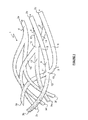
- the guide comprises three entries referenced 2a, 2b, 2c. From each entry extends at least one branch.
- the branch 4 extends from the inlet 2a.
- a portion of the substantially cylindrical guide is defined, by branch, in a preferred and nonlimiting manner of essentially circular cross-section, able to guide the light and having two ends.
- An end may be an entry or an exit of the guide or an end of the guide or a device such as a prism associated with the guide or may partially form an intersection of several branches.
- the guide comprises at least one intersection between at least four branches.
- some of the intersections defined by at least four branches are referenced 10 and 15.
- the intersection 10 is formed by the branches 5, 6, 11, 12.
- the upstream and downstream are defined with respect to the direction of propagation of the light from a source placed near an entrance of the guide.
- the branch 5 has a downstream end 8 defining part of the intersection 10.
- the branch 6 has a downstream end 9 also partly defining the intersection 10.
- the upstream ends of the downstream branches 11 and 12 also partly define the intersection 10. It is the same for the intersection 15 formed in part by the downstream ends 13 and 14 of the upstream branches 5 'and 6' and by the downstream branches 16, 17 extending from this end 15.
- the guide comprises a plurality of intersections and branches forming a mesh.
- the mesh obtained is in three dimensions. This enhances the visibility of the guide 1 and makes it possible to increase very significantly the variety of patterns that can be made.
- the input branches 4, 5, 5 ', 6, 6' intermingle, overlap, form branches or on the contrary merge with each other.
- the resulting guide visually presents an organic or biological structure.
- the casing of the guide 1 is partly at least diffusing.
- at least part of the light entering the guide through the entry (s) escapes through the outer surface of the branches and / or intersections.
- the portion of light that is diffused through the guiding envelope is greater than 70% to the light that penetrates the interior of the guide.
- the remaining portion of light can be transmitted through the outputs 3a to 3f. Additionally, some of the non-diffused light through the envelope of the guide 1 may be transmitted to an optical device such as a prism.
- the shape of the guide is also arranged so as to circumvent or wrap other elements constituting the optical unit.
- the optical unit typically a projector incorporates a lens 60. This lens 60 does not interfere in the optical system of the guide.
- all of the light or at least 90% of the light entering the guide is diffused through the surface of the branches and intersections.
- the entire guide diffuses light. Specifically, the entire area or at least 80% of the guide envelope is diffusing.
- the guide does not have branches, intersections, portions of branches or portions of intersections that do not diffuse light towards the outside of the guide. Thus, seen from the outside, all the surface visible by an observer is illuminated.
- the walls of the guide which are visible from outside the optical unit (projector for example) in which the guide is incorporated are diffusing.
- the guide diffuse as well as the directions that are actually visible in use. For the same incoming luminous flux, the visibility of the guide will be stronger
- a diffusing coating For example, this coating can be deposited on the entire surface disposed opposite the guide, on the bottom of the optical unit consisting for example of a projector housing.
- the guide is arranged so that the diffusion of light on its surface is substantially homogeneous. Thus an observer will not perceive surface portions that diffuse significantly more light than other portions.
- the guide In order to facilitate the diffusion of light, it is expected that the guide, at least on its inner surface, has means for diffusing light. These means may be a diffusive surface state. These means may also be micro-recesses, for example created by laser, forming diffusive micro-prisms. Typically, the size of a hollow is of the order of 0.5 mm in diameter
- the upstream branches of the intersections form between them angles less than 60 °.
- the branches 5 and 6, at their downstream ends 8 and 9 form an angle less than 60 °.
- this angle is less than 40 °.
- the branches 5 'and 6', at their downstream ends 13 and 14, form an angle less than 60 ° and preferably 40 °.
- the branches of the guide can be in two or three dimensions. Preferably, they are in three dimensions to help make highly visible and identifiable the light pattern generated by the diffusing walls of the guide.
- the radius of curvature is less than 150mm.
- the branch section 2 is between 50mm and 400mm 2, preferably between 100 and 250mm 2.
- the guide has an input face intended to be arranged with respect to the light source.
- the input face is substantially perpendicular to the observation direction of an observer of the guide during use of the latter.
- the observation direction is a substantially longitudinal horizontal direction at the vehicle's advance. Observers, whether pedestrians or vehicles arriving in the opposite direction, have a very good visibility of the guide.
- the light source has a main direction of light emission. This main direction is substantially perpendicular to the entrance face of the guide.
- the guide comprises a monolithic part comprising all the branches and intersections. This facilitates the assembly of the optical unit within which the guide is incorporated. In addition, the robustness of the latter is enhanced, which is advantageous when the optical unit is integrated in a vehicle. In addition, the light transmission problems between branches belonging to two separate rooms.
- the guides are formed of a monolithic piece.
- a guide according to the invention by molding. More specifically, and especially for the formation of guides in three dimensions and possibly having a mesh, it will be possible to use a method of overmolding the same transparent material.
- a material such as PMMA (polymethyl methacrylate) or polycarbonate with high light transmission.
- PMMA polymethyl methacrylate
- polycarbonate polycarbonate
- This type of material provides good light guidance while allowing to enhance its diffusivity at the outer walls by a work of its surface state.
- the production of complex shapes for example in three dimensions and / or allowing a mesh, is relatively easy.
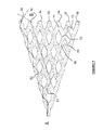
- the guide comprises two inputs 2a, 2b. Entry 2a gives rise to two branches 4, 4 '.
- the inlet 2b gives rise to the branch 5.
- the branches 4 and 5 meet at their downstream ends 26, 27 and form part of the intersection 25.
- the intersection 25 is extended by the downstream branches 28 and 29.
- the branch 29 and a branch 21 meet to form the intersection 20 in part, intersection 20 of which depart the branches downstream 23 and 24.
- the branches 30, 31, 32, 33 join to form an end 34 of the guide.
- the entire inner surface of the guide is diffusing.
- the end 34 transmits significantly more light per unit area than the other surface portions of the guide to ensure the photometric values required by the regulations.
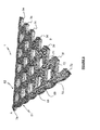
- the figures 3 and 4 are other views of the guide illustrated in figure 2 . These figures show the strong curvature of the guide. This gives it a very specific visual appearance close to a biological form. It is clear from this embodiment that at least some branches of the guide can be in three dimensions.
- the branch referenced 19 is for example in three dimensions.
- all the branches of the guide are in three dimensions. This is so for the guides illustrated at Figures 1 to 5 for example.
- the figure 5 presents an optical unit according to the invention seen according to a quarter front face of a motor vehicle.
- a bumper portion 54 is also shown.
- a guide 1 is integrated in the optical unit 100.
- This guide has three inputs 2a, 2b, 2c. It also includes intersections 51 and 52 formed of four branches each, two upstream and two downstream.
- This guide 1 is substantially planar. It rests on a support 55. It can be planned not to allow light to escape through the walls of the guide facing the support 55 to improve the visibility of the guide 1 perceived by an outside observer.
- the front of the guide 1 to be made easily visible is bent forward to give the guide 1 a three-dimensional shape.
- the guide illustrated in figures 6 and 7 is substantially plane. It comprises an input 2a intended to be associated with an unillustrated light source. It comprises a plurality of intersections such as that referenced 70. This intersection 70 is formed by the upstream branches 68, 69 and by the downstream branches 71, 72. figure 7 illustrates two examples of light paths 61, 62. It thus clearly appears that from the input 2a, all the outputs 3a to 3f can be reached by the luminous flux.
- the invention proposes a solution for improving the visibility of the vehicle incorporating a guide according to the invention and that this guide can be easily obtained while allowing to form highly visible patterns, various shapes and possibly very complex.
- a guide according to the invention is integrated in an optical unit such as a projector performing a lighting or signaling function such as a direction indication function, a position light function or a function daytime running lights.
- a lighting or signaling function such as a direction indication function, a position light function or a function daytime running lights.
Applications Claiming Priority (1)
| Application Number | Priority Date | Filing Date | Title |
|---|---|---|---|
| FR1157585A FR2979437B1 (fr) | 2011-08-29 | 2011-08-29 | Guide de lumiere pour unite optique |
Publications (2)
| Publication Number | Publication Date |
|---|---|
| EP2565689A1 true EP2565689A1 (de) | 2013-03-06 |
| EP2565689B1 EP2565689B1 (de) | 2017-08-30 |
Family
ID=46514259
Family Applications (1)
| Application Number | Title | Priority Date | Filing Date |
|---|---|---|---|
| EP12177701.5A Active EP2565689B1 (de) | 2011-08-29 | 2012-07-24 | Lichtwellenleiter für optische Einheit |
Country Status (2)
| Country | Link |
|---|---|
| EP (1) | EP2565689B1 (de) |
| FR (1) | FR2979437B1 (de) |
Cited By (3)
| Publication number | Priority date | Publication date | Assignee | Title |
|---|---|---|---|---|
| EP2803905A1 (de) * | 2013-05-14 | 2014-11-19 | Automotive Lighting Reutlingen GmbH | Kraftfahrzeugbeleuchtungseinrichtung mit einer Lichtleiteranordnung |
| CN110242931A (zh) * | 2019-06-10 | 2019-09-17 | 马瑞利汽车零部件(芜湖)有限公司 | 立体发光且具有动态视觉效果的汽车照明装置 |
| FR3092900A1 (fr) * | 2019-02-14 | 2020-08-21 | Psa Automobiles Sa | Dispositif d’éclairage et/ou de signalisation lumineuse pour véhicule automobile. |
Citations (3)
| Publication number | Priority date | Publication date | Assignee | Title |
|---|---|---|---|---|
| DE102005029363A1 (de) * | 2005-06-24 | 2007-01-04 | Automotive Lighting Reutlingen Gmbh | Lichtleitstruktur |
| FR2904680A1 (fr) * | 2006-08-04 | 2008-02-08 | Automotive Lighting Reutlingen | Feu de vehicule |
| US20090010021A1 (en) * | 2007-07-06 | 2009-01-08 | Smith Jeffrey T | Recreational apparatus and method of making the same |
-
2011
- 2011-08-29 FR FR1157585A patent/FR2979437B1/fr active Active
-
2012
- 2012-07-24 EP EP12177701.5A patent/EP2565689B1/de active Active
Patent Citations (3)
| Publication number | Priority date | Publication date | Assignee | Title |
|---|---|---|---|---|
| DE102005029363A1 (de) * | 2005-06-24 | 2007-01-04 | Automotive Lighting Reutlingen Gmbh | Lichtleitstruktur |
| FR2904680A1 (fr) * | 2006-08-04 | 2008-02-08 | Automotive Lighting Reutlingen | Feu de vehicule |
| US20090010021A1 (en) * | 2007-07-06 | 2009-01-08 | Smith Jeffrey T | Recreational apparatus and method of making the same |
Cited By (4)
| Publication number | Priority date | Publication date | Assignee | Title |
|---|---|---|---|---|
| EP2803905A1 (de) * | 2013-05-14 | 2014-11-19 | Automotive Lighting Reutlingen GmbH | Kraftfahrzeugbeleuchtungseinrichtung mit einer Lichtleiteranordnung |
| US9562663B2 (en) | 2013-05-14 | 2017-02-07 | Automotive Lighting Reutlingen Gmbh | Lighting device in a motor vehicle with a light conductor arrangement |
| FR3092900A1 (fr) * | 2019-02-14 | 2020-08-21 | Psa Automobiles Sa | Dispositif d’éclairage et/ou de signalisation lumineuse pour véhicule automobile. |
| CN110242931A (zh) * | 2019-06-10 | 2019-09-17 | 马瑞利汽车零部件(芜湖)有限公司 | 立体发光且具有动态视觉效果的汽车照明装置 |
Also Published As
| Publication number | Publication date |
|---|---|
| EP2565689B1 (de) | 2017-08-30 |
| FR2979437B1 (fr) | 2014-07-11 |
| FR2979437A1 (fr) | 2013-03-01 |
Similar Documents
| Publication | Publication Date | Title |
|---|---|---|
| EP2510277B1 (de) | Lanterne oder positionsleuchte für kraftfahrzeugleuchte | |
| EP2270389B1 (de) | Optische Vorrichtung, insbesondere für Kraftfahrzeuge | |
| EP1895228B1 (de) | Vorrichtung zur Beleuchtung oder Signalisierung vom Typ Hochleistungs-Lichtwellenleiter für Kraftfahrzeuge | |
| EP2476947B1 (de) | Vorrichtung zur Beleuchtung oder Signalisierung mittels Lichtwellenleiter für Kraftfahrzeug | |
| EP1775511B1 (de) | Kfz-Signal- und/oder Beleuchtungseinrichtung mit einem Lichtleiter | |
| EP3390900B1 (de) | Lichteinheit, insbesondere für kfz-bremslicht | |
| EP1610158B1 (de) | Signalvorrichtung mit Lichtleiter | |
| EP3014172B1 (de) | Indirektbeleuchtungsvorrichtung für ein kraftfahrzeugrücklicht | |
| EP3150907B1 (de) | Optische vorrichtung und system zur signalisierung und/oder beleuchtung für kraftfahrzeug | |
| EP2317214A1 (de) | Vorrichtung zur Beleuchtung und/oder Signalisierung für Kraftfahrzeuge, die einen Lichtwellenleiter umfasst | |
| FR2972975A1 (fr) | Unite optique pour dispositif de signalisation et/ou d'eclairage | |
| FR2934353A1 (fr) | Systeme optique avec fonction d'eclairage a large surface d'emission pour vehicule automobile | |
| EP2738453A1 (de) | Lichtwellenleiter für eine optische Vorrichtung, insbesondere zur Beleuchtung und/oder Signalisierung | |
| EP1801492A1 (de) | Beleuchtungseinrichtung mit Lichtleitstab für Kraftfahrzeug | |
| EP1992868A1 (de) | Beleuchtungseinrichtung für Kraftfahrzeuge | |
| EP2101202A1 (de) | Lichtsignalvorrichtung für Fahrrad | |
| EP2565689B1 (de) | Lichtwellenleiter für optische Einheit | |
| EP2809985A1 (de) | Vorrichtung zur vereinheitlichung des aussehens von motorfahrzeug-signalleuchten | |
| EP2703220B1 (de) | Vorrichtung zur Beleuchtung und/oder Signalisierung für Kraftfahrzeug | |
| EP3045804B1 (de) | Kraftfahrzeugleuchtvorrichtung mit lichtwellenleiter mit einem nach hinten gekrümmten teil | |
| FR2995969A1 (fr) | Systeme optique de vehicule automobile comprenant une nappe de guidage de lumiere | |
| EP3303911B1 (de) | Lichtleiter für kraftfahrzeugbeleuchtungs- und/oder signalisierungsvorrichtung | |
| EP3594563B1 (de) | Beleuchtungsvorrichtung mit linse, die durch ein empfangslicht beleuchtet wird | |
| FR3062708A1 (fr) | Bloc optique de vehicule a face interne eclairee et visible de l’exterieur | |
| FR3121500A1 (fr) | Dispositif lumineux pour un véhicule automobile apte à créer un effet optique connu sous le nom de moiré. |
Legal Events
| Date | Code | Title | Description |
|---|---|---|---|
| PUAI | Public reference made under article 153(3) epc to a published international application that has entered the european phase |
Free format text: ORIGINAL CODE: 0009012 |
|
| AK | Designated contracting states |
Kind code of ref document: A1 Designated state(s): AL AT BE BG CH CY CZ DE DK EE ES FI FR GB GR HR HU IE IS IT LI LT LU LV MC MK MT NL NO PL PT RO RS SE SI SK SM TR |
|
| AX | Request for extension of the european patent |
Extension state: BA ME |
|
| 17P | Request for examination filed |
Effective date: 20130807 |
|
| RBV | Designated contracting states (corrected) |
Designated state(s): AL AT BE BG CH CY CZ DE DK EE ES FI FR GB GR HR HU IE IS IT LI LT LU LV MC MK MT NL NO PL PT RO RS SE SI SK SM TR |
|
| 17Q | First examination report despatched |
Effective date: 20151221 |
|
| GRAP | Despatch of communication of intention to grant a patent |
Free format text: ORIGINAL CODE: EPIDOSNIGR1 |
|
| INTG | Intention to grant announced |
Effective date: 20170315 |
|
| GRAS | Grant fee paid |
Free format text: ORIGINAL CODE: EPIDOSNIGR3 |
|
| GRAA | (expected) grant |
Free format text: ORIGINAL CODE: 0009210 |
|
| AK | Designated contracting states |
Kind code of ref document: B1 Designated state(s): AL AT BE BG CH CY CZ DE DK EE ES FI FR GB GR HR HU IE IS IT LI LT LU LV MC MK MT NL NO PL PT RO RS SE SI SK SM TR |
|
| REG | Reference to a national code |
Ref country code: GB Ref legal event code: FG4D Free format text: NOT ENGLISH |
|
| REG | Reference to a national code |
Ref country code: CH Ref legal event code: EP |
|
| REG | Reference to a national code |
Ref country code: AT Ref legal event code: REF Ref document number: 924106 Country of ref document: AT Kind code of ref document: T Effective date: 20170915 |
|
| REG | Reference to a national code |
Ref country code: IE Ref legal event code: FG4D Free format text: LANGUAGE OF EP DOCUMENT: FRENCH |
|
| REG | Reference to a national code |
Ref country code: DE Ref legal event code: R096 Ref document number: 602012036553 Country of ref document: DE |
|
| REG | Reference to a national code |
Ref country code: NL Ref legal event code: MP Effective date: 20170830 |
|
| REG | Reference to a national code |
Ref country code: LT Ref legal event code: MG4D |
|
| REG | Reference to a national code |
Ref country code: AT Ref legal event code: MK05 Ref document number: 924106 Country of ref document: AT Kind code of ref document: T Effective date: 20170830 |
|
| PG25 | Lapsed in a contracting state [announced via postgrant information from national office to epo] |
Ref country code: AT Free format text: LAPSE BECAUSE OF FAILURE TO SUBMIT A TRANSLATION OF THE DESCRIPTION OR TO PAY THE FEE WITHIN THE PRESCRIBED TIME-LIMIT Effective date: 20170830 Ref country code: FI Free format text: LAPSE BECAUSE OF FAILURE TO SUBMIT A TRANSLATION OF THE DESCRIPTION OR TO PAY THE FEE WITHIN THE PRESCRIBED TIME-LIMIT Effective date: 20170830 Ref country code: NO Free format text: LAPSE BECAUSE OF FAILURE TO SUBMIT A TRANSLATION OF THE DESCRIPTION OR TO PAY THE FEE WITHIN THE PRESCRIBED TIME-LIMIT Effective date: 20171130 Ref country code: LT Free format text: LAPSE BECAUSE OF FAILURE TO SUBMIT A TRANSLATION OF THE DESCRIPTION OR TO PAY THE FEE WITHIN THE PRESCRIBED TIME-LIMIT Effective date: 20170830 Ref country code: HR Free format text: LAPSE BECAUSE OF FAILURE TO SUBMIT A TRANSLATION OF THE DESCRIPTION OR TO PAY THE FEE WITHIN THE PRESCRIBED TIME-LIMIT Effective date: 20170830 Ref country code: SE Free format text: LAPSE BECAUSE OF FAILURE TO SUBMIT A TRANSLATION OF THE DESCRIPTION OR TO PAY THE FEE WITHIN THE PRESCRIBED TIME-LIMIT Effective date: 20170830 |
|
| PG25 | Lapsed in a contracting state [announced via postgrant information from national office to epo] |
Ref country code: BG Free format text: LAPSE BECAUSE OF FAILURE TO SUBMIT A TRANSLATION OF THE DESCRIPTION OR TO PAY THE FEE WITHIN THE PRESCRIBED TIME-LIMIT Effective date: 20171130 Ref country code: RS Free format text: LAPSE BECAUSE OF FAILURE TO SUBMIT A TRANSLATION OF THE DESCRIPTION OR TO PAY THE FEE WITHIN THE PRESCRIBED TIME-LIMIT Effective date: 20170830 Ref country code: ES Free format text: LAPSE BECAUSE OF FAILURE TO SUBMIT A TRANSLATION OF THE DESCRIPTION OR TO PAY THE FEE WITHIN THE PRESCRIBED TIME-LIMIT Effective date: 20170830 Ref country code: LV Free format text: LAPSE BECAUSE OF FAILURE TO SUBMIT A TRANSLATION OF THE DESCRIPTION OR TO PAY THE FEE WITHIN THE PRESCRIBED TIME-LIMIT Effective date: 20170830 Ref country code: GR Free format text: LAPSE BECAUSE OF FAILURE TO SUBMIT A TRANSLATION OF THE DESCRIPTION OR TO PAY THE FEE WITHIN THE PRESCRIBED TIME-LIMIT Effective date: 20171201 Ref country code: IS Free format text: LAPSE BECAUSE OF FAILURE TO SUBMIT A TRANSLATION OF THE DESCRIPTION OR TO PAY THE FEE WITHIN THE PRESCRIBED TIME-LIMIT Effective date: 20171230 |
|
| PG25 | Lapsed in a contracting state [announced via postgrant information from national office to epo] |
Ref country code: NL Free format text: LAPSE BECAUSE OF FAILURE TO SUBMIT A TRANSLATION OF THE DESCRIPTION OR TO PAY THE FEE WITHIN THE PRESCRIBED TIME-LIMIT Effective date: 20170830 |
|
| PG25 | Lapsed in a contracting state [announced via postgrant information from national office to epo] |
Ref country code: CZ Free format text: LAPSE BECAUSE OF FAILURE TO SUBMIT A TRANSLATION OF THE DESCRIPTION OR TO PAY THE FEE WITHIN THE PRESCRIBED TIME-LIMIT Effective date: 20170830 Ref country code: RO Free format text: LAPSE BECAUSE OF FAILURE TO SUBMIT A TRANSLATION OF THE DESCRIPTION OR TO PAY THE FEE WITHIN THE PRESCRIBED TIME-LIMIT Effective date: 20170830 Ref country code: PL Free format text: LAPSE BECAUSE OF FAILURE TO SUBMIT A TRANSLATION OF THE DESCRIPTION OR TO PAY THE FEE WITHIN THE PRESCRIBED TIME-LIMIT Effective date: 20170830 Ref country code: DK Free format text: LAPSE BECAUSE OF FAILURE TO SUBMIT A TRANSLATION OF THE DESCRIPTION OR TO PAY THE FEE WITHIN THE PRESCRIBED TIME-LIMIT Effective date: 20170830 |
|
| PG25 | Lapsed in a contracting state [announced via postgrant information from national office to epo] |
Ref country code: EE Free format text: LAPSE BECAUSE OF FAILURE TO SUBMIT A TRANSLATION OF THE DESCRIPTION OR TO PAY THE FEE WITHIN THE PRESCRIBED TIME-LIMIT Effective date: 20170830 Ref country code: SK Free format text: LAPSE BECAUSE OF FAILURE TO SUBMIT A TRANSLATION OF THE DESCRIPTION OR TO PAY THE FEE WITHIN THE PRESCRIBED TIME-LIMIT Effective date: 20170830 Ref country code: IT Free format text: LAPSE BECAUSE OF FAILURE TO SUBMIT A TRANSLATION OF THE DESCRIPTION OR TO PAY THE FEE WITHIN THE PRESCRIBED TIME-LIMIT Effective date: 20170830 Ref country code: SM Free format text: LAPSE BECAUSE OF FAILURE TO SUBMIT A TRANSLATION OF THE DESCRIPTION OR TO PAY THE FEE WITHIN THE PRESCRIBED TIME-LIMIT Effective date: 20170830 |
|
| REG | Reference to a national code |
Ref country code: DE Ref legal event code: R097 Ref document number: 602012036553 Country of ref document: DE |
|
| PLBE | No opposition filed within time limit |
Free format text: ORIGINAL CODE: 0009261 |
|
| STAA | Information on the status of an ep patent application or granted ep patent |
Free format text: STATUS: NO OPPOSITION FILED WITHIN TIME LIMIT |
|
| REG | Reference to a national code |
Ref country code: FR Ref legal event code: PLFP Year of fee payment: 7 |
|
| 26N | No opposition filed |
Effective date: 20180531 |
|
| PG25 | Lapsed in a contracting state [announced via postgrant information from national office to epo] |
Ref country code: SI Free format text: LAPSE BECAUSE OF FAILURE TO SUBMIT A TRANSLATION OF THE DESCRIPTION OR TO PAY THE FEE WITHIN THE PRESCRIBED TIME-LIMIT Effective date: 20170830 |
|
| PG25 | Lapsed in a contracting state [announced via postgrant information from national office to epo] |
Ref country code: MT Free format text: LAPSE BECAUSE OF FAILURE TO SUBMIT A TRANSLATION OF THE DESCRIPTION OR TO PAY THE FEE WITHIN THE PRESCRIBED TIME-LIMIT Effective date: 20170830 |
|
| REG | Reference to a national code |
Ref country code: CH Ref legal event code: PL |
|
| GBPC | Gb: european patent ceased through non-payment of renewal fee |
Effective date: 20180724 |
|
| PG25 | Lapsed in a contracting state [announced via postgrant information from national office to epo] |
Ref country code: LU Free format text: LAPSE BECAUSE OF NON-PAYMENT OF DUE FEES Effective date: 20180724 Ref country code: MC Free format text: LAPSE BECAUSE OF FAILURE TO SUBMIT A TRANSLATION OF THE DESCRIPTION OR TO PAY THE FEE WITHIN THE PRESCRIBED TIME-LIMIT Effective date: 20170830 |
|
| REG | Reference to a national code |
Ref country code: BE Ref legal event code: MM Effective date: 20180731 |
|
| REG | Reference to a national code |
Ref country code: IE Ref legal event code: MM4A |
|
| PG25 | Lapsed in a contracting state [announced via postgrant information from national office to epo] |
Ref country code: CH Free format text: LAPSE BECAUSE OF NON-PAYMENT OF DUE FEES Effective date: 20180731 Ref country code: IE Free format text: LAPSE BECAUSE OF NON-PAYMENT OF DUE FEES Effective date: 20180724 Ref country code: GB Free format text: LAPSE BECAUSE OF NON-PAYMENT OF DUE FEES Effective date: 20180724 Ref country code: LI Free format text: LAPSE BECAUSE OF NON-PAYMENT OF DUE FEES Effective date: 20180731 |
|
| PG25 | Lapsed in a contracting state [announced via postgrant information from national office to epo] |
Ref country code: BE Free format text: LAPSE BECAUSE OF NON-PAYMENT OF DUE FEES Effective date: 20180731 |
|
| PG25 | Lapsed in a contracting state [announced via postgrant information from national office to epo] |
Ref country code: TR Free format text: LAPSE BECAUSE OF FAILURE TO SUBMIT A TRANSLATION OF THE DESCRIPTION OR TO PAY THE FEE WITHIN THE PRESCRIBED TIME-LIMIT Effective date: 20170830 |
|
| PG25 | Lapsed in a contracting state [announced via postgrant information from national office to epo] |
Ref country code: PT Free format text: LAPSE BECAUSE OF FAILURE TO SUBMIT A TRANSLATION OF THE DESCRIPTION OR TO PAY THE FEE WITHIN THE PRESCRIBED TIME-LIMIT Effective date: 20170830 Ref country code: HU Free format text: LAPSE BECAUSE OF FAILURE TO SUBMIT A TRANSLATION OF THE DESCRIPTION OR TO PAY THE FEE WITHIN THE PRESCRIBED TIME-LIMIT; INVALID AB INITIO Effective date: 20120724 |
|
| PG25 | Lapsed in a contracting state [announced via postgrant information from national office to epo] |
Ref country code: CY Free format text: LAPSE BECAUSE OF FAILURE TO SUBMIT A TRANSLATION OF THE DESCRIPTION OR TO PAY THE FEE WITHIN THE PRESCRIBED TIME-LIMIT Effective date: 20170830 Ref country code: MK Free format text: LAPSE BECAUSE OF NON-PAYMENT OF DUE FEES Effective date: 20170830 |
|
| PG25 | Lapsed in a contracting state [announced via postgrant information from national office to epo] |
Ref country code: AL Free format text: LAPSE BECAUSE OF FAILURE TO SUBMIT A TRANSLATION OF THE DESCRIPTION OR TO PAY THE FEE WITHIN THE PRESCRIBED TIME-LIMIT Effective date: 20170830 |
|
| P01 | Opt-out of the competence of the unified patent court (upc) registered |
Effective date: 20230528 |
|
| PGFP | Annual fee paid to national office [announced via postgrant information from national office to epo] |
Ref country code: FR Payment date: 20230727 Year of fee payment: 12 Ref country code: DE Payment date: 20230712 Year of fee payment: 12 |