EP2565663B1 - Tumor margin assessment of ex-vivo sample - Google Patents
Tumor margin assessment of ex-vivo sample Download PDFInfo
- Publication number
- EP2565663B1 EP2565663B1 EP12181943.7A EP12181943A EP2565663B1 EP 2565663 B1 EP2565663 B1 EP 2565663B1 EP 12181943 A EP12181943 A EP 12181943A EP 2565663 B1 EP2565663 B1 EP 2565663B1
- Authority
- EP
- European Patent Office
- Prior art keywords
- tissue
- sample holder
- sample
- coil
- sensitive region
- Prior art date
- Legal status (The legal status is an assumption and is not a legal conclusion. Google has not performed a legal analysis and makes no representation as to the accuracy of the status listed.)
- Active
Links
- 206010028980 Neoplasm Diseases 0.000 title claims description 29
- 238000000034 method Methods 0.000 claims description 16
- 238000003384 imaging method Methods 0.000 claims description 10
- 239000011159 matrix material Substances 0.000 claims description 10
- 230000003068 static effect Effects 0.000 claims description 7
- 230000002093 peripheral effect Effects 0.000 claims description 6
- 238000005259 measurement Methods 0.000 claims description 5
- 230000001788 irregular Effects 0.000 claims description 4
- 239000003550 marker Substances 0.000 claims description 3
- 238000002595 magnetic resonance imaging Methods 0.000 description 35
- 210000001519 tissue Anatomy 0.000 description 34
- 210000000481 breast Anatomy 0.000 description 9
- 238000001208 nuclear magnetic resonance pulse sequence Methods 0.000 description 7
- 230000035945 sensitivity Effects 0.000 description 4
- 238000009792 diffusion process Methods 0.000 description 3
- 230000001575 pathological effect Effects 0.000 description 3
- 230000002238 attenuated effect Effects 0.000 description 2
- 201000011510 cancer Diseases 0.000 description 2
- 238000011156 evaluation Methods 0.000 description 2
- 230000005415 magnetization Effects 0.000 description 2
- 230000000149 penetrating effect Effects 0.000 description 2
- 206010006187 Breast cancer Diseases 0.000 description 1
- 208000026310 Breast neoplasm Diseases 0.000 description 1
- 230000005856 abnormality Effects 0.000 description 1
- 238000001574 biopsy Methods 0.000 description 1
- 210000004027 cell Anatomy 0.000 description 1
- 238000001514 detection method Methods 0.000 description 1
- 238000002597 diffusion-weighted imaging Methods 0.000 description 1
- 238000007387 excisional biopsy Methods 0.000 description 1
- 210000001165 lymph node Anatomy 0.000 description 1
- 230000036210 malignancy Effects 0.000 description 1
- 238000013507 mapping Methods 0.000 description 1
- 230000003287 optical effect Effects 0.000 description 1
- 238000012634 optical imaging Methods 0.000 description 1
- 238000010827 pathological analysis Methods 0.000 description 1
- 238000012335 pathological evaluation Methods 0.000 description 1
- 230000007170 pathology Effects 0.000 description 1
- 238000003825 pressing Methods 0.000 description 1
- 238000001959 radiotherapy Methods 0.000 description 1
- 239000011343 solid material Substances 0.000 description 1
- 239000000439 tumor marker Substances 0.000 description 1
- 238000002604 ultrasonography Methods 0.000 description 1
Images


Classifications
-
- G—PHYSICS
- G01—MEASURING; TESTING
- G01R—MEASURING ELECTRIC VARIABLES; MEASURING MAGNETIC VARIABLES
- G01R33/00—Arrangements or instruments for measuring magnetic variables
- G01R33/20—Arrangements or instruments for measuring magnetic variables involving magnetic resonance
- G01R33/44—Arrangements or instruments for measuring magnetic variables involving magnetic resonance using nuclear magnetic resonance [NMR]
- G01R33/48—NMR imaging systems
- G01R33/483—NMR imaging systems with selection of signals or spectra from particular regions of the volume, e.g. in vivo spectroscopy
-
- G—PHYSICS
- G01—MEASURING; TESTING
- G01R—MEASURING ELECTRIC VARIABLES; MEASURING MAGNETIC VARIABLES
- G01R33/00—Arrangements or instruments for measuring magnetic variables
- G01R33/20—Arrangements or instruments for measuring magnetic variables involving magnetic resonance
- G01R33/28—Details of apparatus provided for in groups G01R33/44 - G01R33/64
- G01R33/30—Sample handling arrangements, e.g. sample cells, spinning mechanisms
-
- G—PHYSICS
- G01—MEASURING; TESTING
- G01R—MEASURING ELECTRIC VARIABLES; MEASURING MAGNETIC VARIABLES
- G01R33/00—Arrangements or instruments for measuring magnetic variables
- G01R33/20—Arrangements or instruments for measuring magnetic variables involving magnetic resonance
- G01R33/44—Arrangements or instruments for measuring magnetic variables involving magnetic resonance using nuclear magnetic resonance [NMR]
- G01R33/48—NMR imaging systems
- G01R33/54—Signal processing systems, e.g. using pulse sequences ; Generation or control of pulse sequences; Operator console
- G01R33/56—Image enhancement or correction, e.g. subtraction or averaging techniques, e.g. improvement of signal-to-noise ratio and resolution
- G01R33/563—Image enhancement or correction, e.g. subtraction or averaging techniques, e.g. improvement of signal-to-noise ratio and resolution of moving material, e.g. flow contrast angiography
- G01R33/56375—Intentional motion of the sample during MR, e.g. moving table imaging
-
- G—PHYSICS
- G01—MEASURING; TESTING
- G01R—MEASURING ELECTRIC VARIABLES; MEASURING MAGNETIC VARIABLES
- G01R33/00—Arrangements or instruments for measuring magnetic variables
- G01R33/20—Arrangements or instruments for measuring magnetic variables involving magnetic resonance
- G01R33/28—Details of apparatus provided for in groups G01R33/44 - G01R33/64
- G01R33/32—Excitation or detection systems, e.g. using radio frequency signals
- G01R33/34—Constructional details, e.g. resonators, specially adapted to MR
- G01R33/341—Constructional details, e.g. resonators, specially adapted to MR comprising surface coils
- G01R33/3415—Constructional details, e.g. resonators, specially adapted to MR comprising surface coils comprising arrays of sub-coils, i.e. phased-array coils with flexible receiver channels
Definitions
- the present invention relates generally to surgical devices and methods for confirming an existence of a clean margin of healthy tissue around an excised tumor, for determining the thickness of the margin.
- a malignant tumor When a malignant tumor is found in a breast, generally treatment involves either mastectomy or lumpectomy, sometimes followed by radiation therapy.
- the location of the tumor is found by different imaging modalities, such as x-ray, ultrasound, CT, MRI and others.
- a portion of the tissue including the cancerous portion and a layer of healthy tissue surrounding the cancerous portion, is excised. It is important that the layer of healthy tissue envelop (enclose) the cancerous portion, to ensure that all the malignancy has been removed.
- This layer is often referred to as a "clean margin", and its depth or thickness may range from 1 cell layer, or about 40 microns, to 10 mm (or other values, depending on the tumor, location and other factors); often a few millimetres is considered a clean margin.
- a pathologist samples the margins of the excised portion at different points, especially suspicious points, to assess whether or not the tissue margins around the outer surface of the excised lump are free of cancerous tissue.
- margin status there are no real-time means to assess margin status (frozen sections done for determining axillary lymph node involvement cannot be done on breast tissue due to high fat content), and standard pathologic evaluation of the excised lump can last a few days to weeks. If pathology results are positive, the patient needs to undergo another operation, until the cancerous tissue has been completely removed.
- US Patent No 7227630 describes a method where the morphology of interest of whether an excisional biopsy in which the tissue taken completely removes the abnormality is, in either case, the tissue which is desired to be excisioned, an excised tissue specimen (18) is encapsulated, preferably as part of the biopsy procedure.
- Terahertz pulsed imaging of human breast tumours describes a method of mapping margins of exposed breast tumours where a Terahertz pulsed imaging scanner imaged breast specimens.
- US Patent No 5162103 describes a sample holder and compactor system (10), for use in an industrial NMR (or like) instrument, wherein particulate non-uniform samples can be loaded and compacted.
- the present invention seeks to provide improved surgical devices and methods for confirming the existence of a clean margin of healthy tissue around an excised tumor, and for determining the thickness of the margin, as described in more detail further below.
- the disclosed invention may be useful in giving real-time feedback to surgeons performing lumpectomy (excision of breast cancer tumors), on whether or not they have completely removed the cancerous tissue, i.e., whether or not the tissue margins around the outer surface of the excised lump are free of cancerous tissue.
- the invention is not intended to replace definitive pathological evaluation, but rather to give the surgeon a real time indication if additional tissue needs to be excised, in order to significantly reduce the re-operation rates.
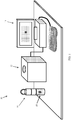
- FIG. 1 illustrates a system 10 for intra-operative margin assessment, constructed and operative in accordance with a non-limiting embodiment of the present invention.
- System 10 is described herein for MRI.
- System 10 includes a relatively small size imaging scanner 12 in the form of an MRI scanner, controlled by an imaging control unit 14, readily available and well known for the particular imaging modality.
- An ex-vivo sample holder 16 holds a tissue sample, referred to as the excised tissue 18 or ex-vivo tissue 18, after it has been removed from the patient, in a predetermined geometry.
- the ex-vivo sample holder 16 is inserted into the imaging scanner 12, which performs automatic scanning of the surface (margins) of the excised tissue 18.
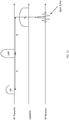
- Fig. 2 illustrates a typical lumpectomy procedure of the prior art.
- the surgeon usually receives the patient with a tumor marker wire 2, which has been inserted into a breast 3 before the operation under ultrasonic or X-ray guidance to mark the center of the tumor.
- the surgeon then uses an excision tool 4 to excise tissue around the marked center of the tumor, to receive an excised lump 18.
- the surgeon makes an effort to excise enough tissue around the tumor so that at a clean margin encloses the tumor, while not excising unnecessarily too much normal tissue in order to conserve as much as possible the normal appearance of the breast.
- the clean margin preferably has a thickness of at least a few millimeters (i.e., the thickness around the tumor which is free of cancerous tissue).
- the invention is not limited to this value, and other thicknesses, such as 40 microns to 1 mm or from 1 mm to 10 mm may be considered a clean margin (or other values, depending on the tumor, location and other factors).
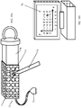
- the ex-vivo sample holder 16 includes a tightening element 20, shown in Fig. 3A in an open position, allowing the excised lump 18 containing a tumor 19 to be inserted into a container 22, which may be cylindrical in shape.
- the excised lump 18 has lump edges 24, which may be very irregular at this stage.
- the tightening element 20 may be shaped like a cylindrical piston or syringe plunger.
- Fig. 3B illustrates tightening element 20 pushed into container 22, which forces the excised lump edges 24 to be bound by the walls of container 22, so that the lump edges 24 generally conform to the inner peripheral shape of container 22 (in the illustrated embodiment, this shape is cylindrical).
- the container 22 may be formed with airways 26 to allow air trapped in the container 22 to be released.
- the container walls may be made of a solid material, a net or mesh, etc.
- the container 22, including the tightening element 20, may be completely disposable (for single use).
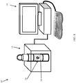
- Fig. 4 illustrates the sample holder 16 holding the ex-vivo sample (excised lump) 18, inserted into scanner 12, which is connected to control unit 14.
- a box-shaped (prismatic) magnet 28 (can be a permanent magnet, an electro-magnet, a superconducting magnet, etc.) is formed with an internal cavity 30, into which sample holder 16 is inserted.
- the magnet 28 can be composed of one piece having a uniform magnetization direction, or of several pieces, each with a different magnetization direction, in order to optimize the static magnetic field (B 0 ) intensity and distribution (profile) within the region of the sample that needs to be measured / imaged.
- the sample holder 16 is inserted into the cavity 30 and is mounted on a rotating stage 32, which rotates the excised lump 18 about a rotation axis 34, such as the symmetry axis of the cylindrical holder 16.
- a transmit/receive coil 36 is mounted adjacent to cavity 30, and is in close proximity to the outer periphery of sample holder 16 with excised lump 18 therein.
- Gradient coils 38 are positioned above and below the height of the excised lump 18. It is noted that the terms “upper”, “lower”, “above”, “below”, “left” and “right”, and the like, only refer to the sense of the drawings and do not limit the invention in any way.
- Fig. 6 illustrates a side-view of the magnetic field patterns and sensitive region 40 generated by the MRI scanner 12 of Fig. 5 .
- the static (permanent or electro-) magnet produces a static magnetic field (B 0 ), which within the volume of the ex-vivo sample, is generally directed along the z-axis.
- the transmit/receive coil 36 once activated, produces a time-varying RF (B 1 ) magnetic field perpendicular to the B 0 field, pointing towards the center of the ex-vivo sample 18.
- the transmit/receive coil 36 can be designed to be large enough relative to the ex-vivo sample height, so that the intensity of the B 1 field is relatively constant throughout the height of the sample.
- the transmit/receive coil 36 can be thin enough so to effectively excite only nuclear spins that are located only within a relatively narrow and superficial sensitive region within the ex-vivo sample, e.g. from the surface of the ex-vivo sample and up to a few millimeters into the sample.
- the depth of the sensitive region 40 into the ex-vivo sample 18 is determined by the coil sensitivity profile, and by the homogeneity of the B 0 field, which can be relatively good if the sensitive region 40 is up to a few millimeters into the sample.
- z-resolution i.e.
- the upper and lower gradient coils 38 can be used, so that when they are activated, they produce gradient (B G ) fields that are aligned along the +z and -z directions respectively.
- the gradient coils 38 can create a B G field pattern that is linear in the z direction.
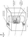
- Fig. 7 illustrates a top-view of the magnetic field patterns and sensitive region 40 generated by the MRI scanner 12 of Fig. 5 .
- the static B 0 field generated by the magnet 28 is aligned along the z direction.
- the B 1 field generated by the transmit/receive coil 36 is directed perpendicularly to the B 0 field, and to the center of the ex-vivo sample 18.
- the sensitive region 40 the shape and dimensions of which are determined mainly by the geometry of the transmit/receive coil 36, extends a few millimeters into the ex-vivo sample 18, and a certain angular aperture out of the entire sample circumference. This way, an angular ( ⁇ ) resolution is achieved, i.e. signals are received only from a specific angular aperture in the sample.
- Fig. 8 illustrates how the margins on the entire circumference of the ex-vivo sample 18 are measured / imaged by the MRI scanner 12 of Fig. 5 .
- the excised lump 18 is rotated by the rotating stage 32 (not shown here, but shown in Fig. 5 ), such as by using a step motor.
- the transmit/receive coil 36 excites and obtains a signal from the sensitive region 40, and uses the z-gradient coils 38 (not shown here, but shown in Fig. 5 ) to create the z-dimension.
- the sample is rotated and a signal from the next angular position is acquired.
- the control unit 14 includes a personal computer (PC) 42, which includes a controller 43 that activates and controls operation of a motor 44 that rotates the rotating stage (not shown in Fig. 9 ) via a motor driver 45.
- PC 42 includes a gate 46 that triggers a gradient driver 47, which drives current through the upper and lower gradient coils 38.
- Digital to analog (D/A) circuitry 48 creates RF pulses which are amplified by an RF amplifier 49 (RF Amp) and transmitted through an RF transmit/receive switch 50 into the transmit/receive coil 36.
- Analog to digital (A/D) circuitry 51 records the MRI signals received by the transmit/receive switch 50 as amplified by a pre-amplifier (Pre-Amp) 52.
- Pre-Amp pre-amplifier
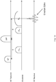
- Fig. 10 illustrates one possible pulse sequence that can be used in conjunction with the MRI scanner 12 of Fig. 5 for obtaining a diffusion-weighted z-profile of the margins of an ex-vivo sample. Similar pulse sequences are well known in the art. Diffusion weighted MRI is specifically known in the art as a very sensitive and specific method to detect cancerous tissue.
- a first (90°) RF pulse followed by a second (180°) RF pulse are given, with a time gap of ⁇ .
- the z-gradient is activated (B G1 ) for a short duration.
- the same z-gradient is activated for a similar duration and amplitude. If the B 0 field is relatively homogenous within the sensitive region and if the spins do not diffuse, then at time 2x ⁇ the spins should be completely refocused to create a gradient echo. The more self-diffusion the spins undergo, the more attenuated the gradient echo will be. In addition, if the z-gradient coil is active during signal acquisition (RF receive), then the gradient echo will contain z-position information. By applying a Fourier-transform to the acquired gradient echo, as is known in the art, a diffusion-weighted z-position vector is generated.
- Fig. 11 illustrates yet another possible pulse sequence that can be used in conjunction with the MRI scanner 12 of Fig. 5 for obtaining a T2-weighted z-profile of the margins of an ex-vivo sample. Similar pulse sequences are well known in the art. T2-weighted MRI is also known in the art to be useful for detecting cancerous tissue. In the sequence of Fig. 11 , a first (90°) RF pulse followed by a second (180°) RF pulse are given, with a time gap of ⁇ , which should be long enough relative to the typical T2 of breast tissue.
- the spins should be completely refocused to create a spin echo.
- the spin echo will contain z-position information.
- a Fourier-transform to the acquired gradient echo, as is known in the art, a T2-weighted z-position vector is generated.
- T1-weighted, parametric ADC (apparent diffusion coefficient) measurement, or any other type of MRI pulse sequence known in the art can be used in conjunction with the disclosed invention.
- the MR image 31 is a pixel matrix, which has two dimensions: z and ⁇ .
- the intensity (or information in general) of each pixel 33 is related to the MR signal acquired at the margins of (up to a few millimeters into) the excised lump.
- one z-vector of pixels is acquired.
- the full margin status map is displayed as the MR image. Pixels that contain different intensities, for example, on diffusion-weighted imaging, may represent a suspected tumor on the margins.
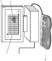
- Fig. 13 illustrates an MRI scanner 13 that can be used for margin assessment of excised lumps, constructed and operative in accordance with another non-limiting embodiment of the present invention.
- a box-shaped (prismatic) magnet 54 creates a static magnetic field (B 0 ) tangent to, i.e., planar with or parallel to, an upper magnet surface 55. It is possible, although not shown here, that at close proximity to the magnet surface 55, a relatively homogeneous magnetic field can be created. Alternatively, many other configurations of magnetic field sources can be designed to create a magnetic field, which is relatively homogenous within a similar plane.
- a transmit coil 56 can be wound on the magnet surface 55, so that when activated, an RF (B 1 ) magnetic field perpendicular to the magnet surface 55 can be generated.
- a matrix of N x M receive coils 58 can be mounted on the magnet surface 55, each with a sensitive region directly adjacent to it.
- the same N x M coil matrix 58 can be used for both transmit and receive.
- the single coil 56 can be used for both transmit and receive. In this latter single-coil configuration, if in-plane 2D resolution is required, then gradients can be used.
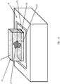
- Fig. 14 illustrates the sensitive region 59 created within the margins of an excised lump 18, using the MRI scanner 13 of Fig. 13 .
- the excised lump 18 is placed in a sample holder 60 that has at least one face which conforms to the shape of the magnet surface 55 of magnet 54 (that is, in this example, sample holder 60 is prismatic, and accordingly, excised lump 18 is forced into a prismatic shape).
- the sample holder 60 holds the excised lump 18 along with the tumor 19 over the magnet, covering over the transmit coil 56 and receive coils 58.
- the sensitive region is defined as the region within the sample in which transmit and receive coils 36 and 38 are effective in exciting and receiving MR signals from nuclear spins.
- the depth of the sensitive region is determined by the sensitivity of the receive coils, which can be limited to just a few millimeters into the tissue - which is the preferred depth of the relevant margins.
- prismatic sample holder 60 containing the lump should be repositioned so that all six faces are on the coils in order to measure all six faces, one face at a time. Alternatively, one may choose to scan only some of the faces.
- the sample holder may be designed to have relatively large upper and lower faces, and very narrow side faces, so that most of the excised lump surface conforms to either upper of lower sample holder faces.
- a control unit 61 includes a PC 62, including a D/A converter 63 that generates RF pulses, amplified by an RF amplifier 64 and transmitted by transmit coil 56, and an A/D converter 65 that records the MRI signals received by the coil matrix 58 and amplified by a pre-amplifier 66.
- the signals received by the N x M coil matrix 58 can be either recorded simultaneously using multiple parallel data acquisition channels, or the active coils can be switched, one by one, group by group, vector by vector, etc. Methods to switch between receive channels or to record signals from multiple channels simultaneously are well known in the art.
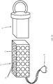
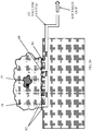
- Sample holder 70 includes a container 71 with integrated receive coils 72 that can be used in conjunction with the magnet and transmit coil configuration (and instead of the receive coil configuration) of Fig. 13 .
- Prismatic container 71 has an integrated matrix of receive coils 72 on each of its faces. All receive coils 72 can be connected via a connector 73 to the MRI scanner during measurement. It can be readily understood that, alternatively or additionally, the transmit coil(s) can be integrated into the ex-vivo sample holder.
- a tightening element 74 is provided for pressing against the excised lump 18.
- Figs. 17A and 17B illustrate the ex-vivo sample holder 70 of Fig. 16 with an excised lump 18 therein.
- Fig. 17A is a general view of the sample holder 70 and Fig. 17B is a transverse cross-section of the same sample holder 70.
- the tightening element 74 is pressed against the lump 18, the lump edges conform to the sample holder shape.
- Each receive coil 72 has a specific sensitive region 75 extending a few millimeters into the lump, so that overall the receive coils cover the entire lump margins. If the tumor (or cancerous tissue) penetrates the sensitive region, and therefore the margins, then the specific coils that are adjacent to the penetrating tumor will detect it.
- Fig. 18 illustrates a possible method for using the ex-vivo sample holder 70 of Fig. 16 , together with the obtained MR image 76, in order to mark the detected tumor on the margin for further pathological examination.
- the pixel matrix and the coil matrix on the sample holder can be similarly coded, e.g. A, B, C... x 1, 2, 3...
- an ink marker 78 can mark the region in the sample that has a suspected penetrating tumor in it.
- the coded positions can guide the pathologist to make a larger number of cuts in regions that are suspected with positive margins, thereby potentially increasing the overall sensitivity of the pathological analysis.
- an automated marking can be designed and incorporated in the scanner itself, either by ink or by electronic means like LEDs integrated into the sample holder.
- Fig. 19 illustrates another embodiment of the MRI scanner 13 of Fig. 13 , in which the sample holder operates with vacuum.
- the excised lump is mounted on a surface 81 of a magnet 80 above receive coils 82.
- Air inlets 84 connected to a vacuum system 86 are incorporated in between the receive coils 82 so that when the excised lump 18 with its irregular surface is mounted on the surface of the magnet 80, the vacuum system 86 can gently pull the tissue on the lump surface 88 to conform it to the magnet surface (as seen in Fig. 20 ), so that the lump margins are within the receive coils sensitive regions.
Landscapes
- Physics & Mathematics (AREA)
- General Physics & Mathematics (AREA)
- Condensed Matter Physics & Semiconductors (AREA)
- Nuclear Medicine, Radiotherapy & Molecular Imaging (AREA)
- Health & Medical Sciences (AREA)
- High Energy & Nuclear Physics (AREA)
- General Health & Medical Sciences (AREA)
- Signal Processing (AREA)
- Engineering & Computer Science (AREA)
- Radiology & Medical Imaging (AREA)
- Vascular Medicine (AREA)
- Optics & Photonics (AREA)
- Spectroscopy & Molecular Physics (AREA)
- Magnetic Resonance Imaging Apparatus (AREA)
Applications Claiming Priority (2)
| Application Number | Priority Date | Filing Date | Title |
|---|---|---|---|
| US30015610P | 2010-02-01 | 2010-02-01 | |
| EP11712359 | 2011-01-31 |
Related Parent Applications (2)
| Application Number | Title | Priority Date | Filing Date |
|---|---|---|---|
| EP11712359.6 Division | 2011-01-31 | ||
| EP11712359 Division | 2010-02-01 | 2011-01-31 |
Publications (2)
| Publication Number | Publication Date |
|---|---|
| EP2565663A1 EP2565663A1 (en) | 2013-03-06 |
| EP2565663B1 true EP2565663B1 (en) | 2016-12-14 |
Family
ID=44010151
Family Applications (1)
| Application Number | Title | Priority Date | Filing Date |
|---|---|---|---|
| EP12181943.7A Active EP2565663B1 (en) | 2010-02-01 | 2011-01-31 | Tumor margin assessment of ex-vivo sample |
Country Status (4)
| Country | Link |
|---|---|
| US (1) | US9310450B2 (enExample) |
| EP (1) | EP2565663B1 (enExample) |
| JP (1) | JP5680110B2 (enExample) |
| WO (1) | WO2011094659A2 (enExample) |
Families Citing this family (9)
| Publication number | Priority date | Publication date | Assignee | Title |
|---|---|---|---|---|
| US10204415B2 (en) | 2012-01-16 | 2019-02-12 | Koninklijke Philips N.V. | Imaging apparatus |
| ES2878548T3 (es) * | 2012-02-26 | 2021-11-19 | Caliber Imaging & Diagnostics Inc | Platina para muestras de tejido para un microscopio de seccionamiento óptico |
| US9689817B2 (en) * | 2012-03-21 | 2017-06-27 | Clear-Cut Medical Ltd. | MRI system for margin assessment of ex-vivo sample |
| US9677869B2 (en) | 2012-12-05 | 2017-06-13 | Perimeter Medical Imaging, Inc. | System and method for generating a wide-field OCT image of a portion of a sample |
| JP2019512083A (ja) * | 2016-02-04 | 2019-05-09 | クリア−カット メディカル リミテッド | 永続磁石配列を使用したmri画像化システム |
| WO2018134793A1 (en) * | 2017-01-23 | 2018-07-26 | Clear-Cut Medical Ltd. | System for ex-vivo nmr inspection of removed tissue |
| EP3655748B1 (en) | 2017-07-18 | 2023-08-09 | Perimeter Medical Imaging, Inc. | Sample container for stabilizing and aligning excised biological tissue samples for ex vivo analysis |
| WO2019222194A1 (en) * | 2018-05-15 | 2019-11-21 | Intuitive Surgical Operations, Inc. | Systems and methods for determining an arrangement of explanted tissue and for displaying tissue information |
| WO2021191748A1 (en) | 2020-03-22 | 2021-09-30 | Clear-Cut Medical Ltd. | Method for extracting multiple t2* values from single set of cpmg data |
Family Cites Families (21)
| Publication number | Priority date | Publication date | Assignee | Title |
|---|---|---|---|---|
| JPS63270037A (ja) * | 1987-04-28 | 1988-11-08 | Olympus Optical Co Ltd | 内視鏡 |
| JPH0435645A (ja) * | 1990-05-31 | 1992-02-06 | Toshiba Corp | 磁気共鳴イメージング装置 |
| US5162103A (en) | 1992-01-17 | 1992-11-10 | Auburn International, Inc. | Sample holder compactor for industrial NMR analysis |
| DE4225001C1 (de) * | 1992-07-29 | 1993-11-18 | Siemens Ag | Stereotaktische Zusatzeinrichtung für Kernspintomographen |
| US6032068A (en) * | 1998-02-19 | 2000-02-29 | The Board Of Trustees Of The Leland Stanford Junior University | Non-invasive measurement of frozen tissue temperature using MRI signal |
| WO2000015021A2 (en) * | 1998-09-14 | 2000-03-23 | Lucid, Inc. | Imaging of surgical biopsies |
| US7227630B1 (en) | 1998-09-14 | 2007-06-05 | Lucid, Inc. | Imaging of surgical biopsies |
| EP1169630B1 (en) | 1999-02-17 | 2017-02-01 | Lucid, Inc. | Cassette for facilitating optical sectioning of a retained tissue specimen |
| US6289682B1 (en) * | 1999-08-25 | 2001-09-18 | David C. Rada | Specimen preparation apparatus |
| US8068896B2 (en) * | 2005-02-25 | 2011-11-29 | Intramedical Imaging, Llc | Detection of radiation labeled sites using a radiation detection probe or camera incorporating a solid state photo-multiplier |
| JP2006247113A (ja) * | 2005-03-10 | 2006-09-21 | Gunma Univ | 腫瘍検出のための画像形成方法及び画像形成ソフトウェア |
| US8038595B2 (en) * | 2006-01-25 | 2011-10-18 | Beth Israel Deaconess Medical Center | Devices and methods for tissue transplant and regeneration |
| WO2007142678A1 (en) | 2006-06-05 | 2007-12-13 | The Johns Hopkins University | Compression device for enhancing normal/abnormal tissue contrast in mri including devices and methods related thereto |
| JP5170686B2 (ja) * | 2006-09-29 | 2013-03-27 | 学校法人慶應義塾 | 核磁気共鳴法を用いた測定装置および測定方法 |
| JP4718410B2 (ja) * | 2006-10-16 | 2011-07-06 | サクラファインテックジャパン株式会社 | 摘出生体組織形状保持材及び生体組織の固定方法 |
| JP5170617B2 (ja) * | 2007-04-24 | 2013-03-27 | 独立行政法人産業技術総合研究所 | 片側開放型磁気回路 |
| US8463361B2 (en) * | 2007-05-24 | 2013-06-11 | Lifewave, Inc. | System and method for non-invasive instantaneous and continuous measurement of cardiac chamber volume |
| US8983580B2 (en) * | 2008-01-18 | 2015-03-17 | The Board Of Trustees Of The University Of Illinois | Low-coherence interferometry and optical coherence tomography for image-guided surgical treatment of solid tumors |
| US8208709B2 (en) * | 2008-04-17 | 2012-06-26 | The Ohio State University Research Foundation | System and method for improved real-time cine imaging |
| JP5335280B2 (ja) * | 2008-05-13 | 2013-11-06 | キヤノン株式会社 | 位置合わせ処理装置、位置合わせ方法、プログラム、及び記憶媒体 |
| US8688193B2 (en) * | 2008-06-26 | 2014-04-01 | Allegheny-Singer Research Institute | Magnetic resonance imager, method and program which continuously applies steady-state free precession to k-space |
-
2011
- 2011-01-31 EP EP12181943.7A patent/EP2565663B1/en active Active
- 2011-01-31 JP JP2012551362A patent/JP5680110B2/ja active Active
- 2011-01-31 US US13/522,353 patent/US9310450B2/en active Active
- 2011-01-31 WO PCT/US2011/023101 patent/WO2011094659A2/en not_active Ceased
Non-Patent Citations (1)
| Title |
|---|
| None * |
Also Published As
| Publication number | Publication date |
|---|---|
| WO2011094659A2 (en) | 2011-08-04 |
| EP2565663A1 (en) | 2013-03-06 |
| US20120299591A1 (en) | 2012-11-29 |
| JP2013519073A (ja) | 2013-05-23 |
| US9310450B2 (en) | 2016-04-12 |
| WO2011094659A3 (en) | 2012-01-05 |
| JP5680110B2 (ja) | 2015-03-04 |
Similar Documents
| Publication | Publication Date | Title |
|---|---|---|
| EP2565663B1 (en) | Tumor margin assessment of ex-vivo sample | |
| Ganslandt et al. | Proton magnetic resonance spectroscopic imaging integrated into image-guided surgery: correlation to standard magnetic resonance imaging and tumor cell density | |
| JP4863610B2 (ja) | 断層撮影イメージングシステム用の標準測定プロトコルの作成方法、コンピュータプログラムを記録したコンピュータ読み取り可能な記録媒体および断層撮影イメージングシステム内に実際対象物の撮像範囲を位置決めする計画方法 | |
| EP2424429B1 (en) | Imaging device for three dimensional anatomical and functional imaging and methods thereof | |
| US20120095322A1 (en) | Devices, systems and methods for multimodal biosensing and imaging | |
| US20090069670A1 (en) | Site marker | |
| Kumar et al. | Transrectal ultrasound‐guided biopsy of prostate voxels identified as suspicious of malignancy on three‐dimensional 1H MR spectroscopic imaging in patients with abnormal digital rectal examination or raised prostate specific antigen level of 4–10 ng/ml | |
| Krieger et al. | Development and preliminary evaluation of an actuated MRI-compatible robotic device for MRI-guided prostate intervention | |
| JPWO2009041534A1 (ja) | 磁気共鳴イメージング装置及びその作動方法、画像診断システム並びに診断方法 | |
| Reichert et al. | Simultaneous slice excitation for accelerated passive marker tracking via phase-only cross correlation (POCC) in MR-guided needle interventions | |
| D'Agostino et al. | Comparison between" In-bore" MRI guided prostate biopsy and standard ultrasound guided biopsy in the patient with suspicious prostate cancer: Preliminary results. | |
| EP2828677B1 (en) | Mri system for margin assessment of ex-vivo sample | |
| WO2020041523A1 (en) | Nuclear magnetic resonance systems and methods for non-invasive and in-vivo measurements using a unilateral magnet | |
| Ward et al. | Registration of in vivo prostate magnetic resonance images to digital histopathology images | |
| Anique et al. | Multiple tissue sample collection device for MRI guided transrectal prostate biopsy: Optimization and MRI compatibility tests | |
| Liu et al. | Prospects for microwave imaging of the lymphatic system in the axillary | |
| US11029268B2 (en) | Hybrid NMR and OCT system | |
| Choi et al. | The clinical value of performing an MRI before prostate biopsy | |
| US20090027052A1 (en) | Method for acquiring measured data | |
| CN112790863B (zh) | 手术器械定位方法、磁共振成像系统以及电子装置 | |
| KR101480413B1 (ko) | B1 정보 획득 방법 및 장치 | |
| WO2024211848A1 (en) | Systems and methods for magnetic resonance imaging calibration | |
| Breen et al. | Three-dimensional correlation of MR images to muscle tissue response for interventional MRI thermal ablation | |
| Mohson et al. | Accuracy of ultrasound guided fine needle aspiration cytology in head and neck lesions | |
| Smith et al. | Excite and receive solenoid radiofrequency coil for MRI‐guided breast interventions |
Legal Events
| Date | Code | Title | Description |
|---|---|---|---|
| PUAI | Public reference made under article 153(3) epc to a published international application that has entered the european phase |
Free format text: ORIGINAL CODE: 0009012 |
|
| 17P | Request for examination filed |
Effective date: 20120828 |
|
| AK | Designated contracting states |
Kind code of ref document: A1 Designated state(s): AL AT BE BG CH CY CZ DE DK EE ES FI FR GB GR HR HU IE IS IT LI LT LU LV MC MK MT NL NO PL PT RO RS SE SI SK SM TR |
|
| AX | Request for extension of the european patent |
Extension state: BA ME |
|
| 17Q | First examination report despatched |
Effective date: 20150428 |
|
| GRAP | Despatch of communication of intention to grant a patent |
Free format text: ORIGINAL CODE: EPIDOSNIGR1 |
|
| INTG | Intention to grant announced |
Effective date: 20160628 |
|
| STAA | Information on the status of an ep patent application or granted ep patent |
Free format text: STATUS: GRANT OF PATENT IS INTENDED |
|
| GRAS | Grant fee paid |
Free format text: ORIGINAL CODE: EPIDOSNIGR3 |
|
| GRAA | (expected) grant |
Free format text: ORIGINAL CODE: 0009210 |
|
| STAA | Information on the status of an ep patent application or granted ep patent |
Free format text: STATUS: THE PATENT HAS BEEN GRANTED |
|
| AK | Designated contracting states |
Kind code of ref document: B1 Designated state(s): AL AT BE BG CH CY CZ DE DK EE ES FI FR GB GR HR HU IE IS IT LI LT LU LV MC MK MT NL NO PL PT RO RS SE SI SK SM TR |
|
| REG | Reference to a national code |
Ref country code: GB Ref legal event code: FG4D |
|
| REG | Reference to a national code |
Ref country code: CH Ref legal event code: EP |
|
| REG | Reference to a national code |
Ref country code: IE Ref legal event code: FG4D |
|
| REG | Reference to a national code |
Ref country code: AT Ref legal event code: REF Ref document number: 854078 Country of ref document: AT Kind code of ref document: T Effective date: 20170115 |
|
| REG | Reference to a national code |
Ref country code: DE Ref legal event code: R096 Ref document number: 602011033511 Country of ref document: DE |
|
| PG25 | Lapsed in a contracting state [announced via postgrant information from national office to epo] |
Ref country code: LV Free format text: LAPSE BECAUSE OF FAILURE TO SUBMIT A TRANSLATION OF THE DESCRIPTION OR TO PAY THE FEE WITHIN THE PRESCRIBED TIME-LIMIT Effective date: 20161214 |
|
| REG | Reference to a national code |
Ref country code: LT Ref legal event code: MG4D |
|
| REG | Reference to a national code |
Ref country code: NL Ref legal event code: MP Effective date: 20161214 |
|
| PG25 | Lapsed in a contracting state [announced via postgrant information from national office to epo] |
Ref country code: GR Free format text: LAPSE BECAUSE OF FAILURE TO SUBMIT A TRANSLATION OF THE DESCRIPTION OR TO PAY THE FEE WITHIN THE PRESCRIBED TIME-LIMIT Effective date: 20170315 Ref country code: SE Free format text: LAPSE BECAUSE OF FAILURE TO SUBMIT A TRANSLATION OF THE DESCRIPTION OR TO PAY THE FEE WITHIN THE PRESCRIBED TIME-LIMIT Effective date: 20161214 Ref country code: LT Free format text: LAPSE BECAUSE OF FAILURE TO SUBMIT A TRANSLATION OF THE DESCRIPTION OR TO PAY THE FEE WITHIN THE PRESCRIBED TIME-LIMIT Effective date: 20161214 Ref country code: NO Free format text: LAPSE BECAUSE OF FAILURE TO SUBMIT A TRANSLATION OF THE DESCRIPTION OR TO PAY THE FEE WITHIN THE PRESCRIBED TIME-LIMIT Effective date: 20170314 |
|
| REG | Reference to a national code |
Ref country code: AT Ref legal event code: MK05 Ref document number: 854078 Country of ref document: AT Kind code of ref document: T Effective date: 20161214 |
|
| PG25 | Lapsed in a contracting state [announced via postgrant information from national office to epo] |
Ref country code: RS Free format text: LAPSE BECAUSE OF FAILURE TO SUBMIT A TRANSLATION OF THE DESCRIPTION OR TO PAY THE FEE WITHIN THE PRESCRIBED TIME-LIMIT Effective date: 20161214 Ref country code: FI Free format text: LAPSE BECAUSE OF FAILURE TO SUBMIT A TRANSLATION OF THE DESCRIPTION OR TO PAY THE FEE WITHIN THE PRESCRIBED TIME-LIMIT Effective date: 20161214 Ref country code: HR Free format text: LAPSE BECAUSE OF FAILURE TO SUBMIT A TRANSLATION OF THE DESCRIPTION OR TO PAY THE FEE WITHIN THE PRESCRIBED TIME-LIMIT Effective date: 20161214 Ref country code: BE Free format text: LAPSE BECAUSE OF NON-PAYMENT OF DUE FEES Effective date: 20170131 |
|
| PG25 | Lapsed in a contracting state [announced via postgrant information from national office to epo] |
Ref country code: NL Free format text: LAPSE BECAUSE OF FAILURE TO SUBMIT A TRANSLATION OF THE DESCRIPTION OR TO PAY THE FEE WITHIN THE PRESCRIBED TIME-LIMIT Effective date: 20161214 |
|
| PG25 | Lapsed in a contracting state [announced via postgrant information from national office to epo] |
Ref country code: SK Free format text: LAPSE BECAUSE OF FAILURE TO SUBMIT A TRANSLATION OF THE DESCRIPTION OR TO PAY THE FEE WITHIN THE PRESCRIBED TIME-LIMIT Effective date: 20161214 Ref country code: CZ Free format text: LAPSE BECAUSE OF FAILURE TO SUBMIT A TRANSLATION OF THE DESCRIPTION OR TO PAY THE FEE WITHIN THE PRESCRIBED TIME-LIMIT Effective date: 20161214 Ref country code: IS Free format text: LAPSE BECAUSE OF FAILURE TO SUBMIT A TRANSLATION OF THE DESCRIPTION OR TO PAY THE FEE WITHIN THE PRESCRIBED TIME-LIMIT Effective date: 20170414 Ref country code: EE Free format text: LAPSE BECAUSE OF FAILURE TO SUBMIT A TRANSLATION OF THE DESCRIPTION OR TO PAY THE FEE WITHIN THE PRESCRIBED TIME-LIMIT Effective date: 20161214 |
|
| PG25 | Lapsed in a contracting state [announced via postgrant information from national office to epo] |
Ref country code: AT Free format text: LAPSE BECAUSE OF FAILURE TO SUBMIT A TRANSLATION OF THE DESCRIPTION OR TO PAY THE FEE WITHIN THE PRESCRIBED TIME-LIMIT Effective date: 20161214 Ref country code: SM Free format text: LAPSE BECAUSE OF FAILURE TO SUBMIT A TRANSLATION OF THE DESCRIPTION OR TO PAY THE FEE WITHIN THE PRESCRIBED TIME-LIMIT Effective date: 20161214 Ref country code: BE Free format text: LAPSE BECAUSE OF FAILURE TO SUBMIT A TRANSLATION OF THE DESCRIPTION OR TO PAY THE FEE WITHIN THE PRESCRIBED TIME-LIMIT Effective date: 20161214 Ref country code: ES Free format text: LAPSE BECAUSE OF FAILURE TO SUBMIT A TRANSLATION OF THE DESCRIPTION OR TO PAY THE FEE WITHIN THE PRESCRIBED TIME-LIMIT Effective date: 20161214 Ref country code: PT Free format text: LAPSE BECAUSE OF FAILURE TO SUBMIT A TRANSLATION OF THE DESCRIPTION OR TO PAY THE FEE WITHIN THE PRESCRIBED TIME-LIMIT Effective date: 20170414 Ref country code: PL Free format text: LAPSE BECAUSE OF FAILURE TO SUBMIT A TRANSLATION OF THE DESCRIPTION OR TO PAY THE FEE WITHIN THE PRESCRIBED TIME-LIMIT Effective date: 20161214 |
|
| REG | Reference to a national code |
Ref country code: CH Ref legal event code: PL |
|
| REG | Reference to a national code |
Ref country code: DE Ref legal event code: R097 Ref document number: 602011033511 Country of ref document: DE |
|
| PG25 | Lapsed in a contracting state [announced via postgrant information from national office to epo] |
Ref country code: MC Free format text: LAPSE BECAUSE OF FAILURE TO SUBMIT A TRANSLATION OF THE DESCRIPTION OR TO PAY THE FEE WITHIN THE PRESCRIBED TIME-LIMIT Effective date: 20161214 |
|
| PLBE | No opposition filed within time limit |
Free format text: ORIGINAL CODE: 0009261 |
|
| STAA | Information on the status of an ep patent application or granted ep patent |
Free format text: STATUS: NO OPPOSITION FILED WITHIN TIME LIMIT |
|
| REG | Reference to a national code |
Ref country code: FR Ref legal event code: ST Effective date: 20170929 |
|
| PG25 | Lapsed in a contracting state [announced via postgrant information from national office to epo] |
Ref country code: CH Free format text: LAPSE BECAUSE OF NON-PAYMENT OF DUE FEES Effective date: 20170131 Ref country code: LI Free format text: LAPSE BECAUSE OF NON-PAYMENT OF DUE FEES Effective date: 20170131 Ref country code: FR Free format text: LAPSE BECAUSE OF NON-PAYMENT OF DUE FEES Effective date: 20170214 |
|
| REG | Reference to a national code |
Ref country code: IE Ref legal event code: MM4A |
|
| 26N | No opposition filed |
Effective date: 20170915 |
|
| PG25 | Lapsed in a contracting state [announced via postgrant information from national office to epo] |
Ref country code: LU Free format text: LAPSE BECAUSE OF NON-PAYMENT OF DUE FEES Effective date: 20170131 Ref country code: DK Free format text: LAPSE BECAUSE OF FAILURE TO SUBMIT A TRANSLATION OF THE DESCRIPTION OR TO PAY THE FEE WITHIN THE PRESCRIBED TIME-LIMIT Effective date: 20161214 |
|
| PG25 | Lapsed in a contracting state [announced via postgrant information from national office to epo] |
Ref country code: SI Free format text: LAPSE BECAUSE OF FAILURE TO SUBMIT A TRANSLATION OF THE DESCRIPTION OR TO PAY THE FEE WITHIN THE PRESCRIBED TIME-LIMIT Effective date: 20161214 Ref country code: IE Free format text: LAPSE BECAUSE OF NON-PAYMENT OF DUE FEES Effective date: 20170131 |
|
| PG25 | Lapsed in a contracting state [announced via postgrant information from national office to epo] |
Ref country code: MT Free format text: LAPSE BECAUSE OF NON-PAYMENT OF DUE FEES Effective date: 20170131 |
|
| PG25 | Lapsed in a contracting state [announced via postgrant information from national office to epo] |
Ref country code: HU Free format text: LAPSE BECAUSE OF FAILURE TO SUBMIT A TRANSLATION OF THE DESCRIPTION OR TO PAY THE FEE WITHIN THE PRESCRIBED TIME-LIMIT; INVALID AB INITIO Effective date: 20110131 |
|
| PG25 | Lapsed in a contracting state [announced via postgrant information from national office to epo] |
Ref country code: RO Free format text: LAPSE BECAUSE OF FAILURE TO SUBMIT A TRANSLATION OF THE DESCRIPTION OR TO PAY THE FEE WITHIN THE PRESCRIBED TIME-LIMIT Effective date: 20161214 Ref country code: BG Free format text: LAPSE BECAUSE OF FAILURE TO SUBMIT A TRANSLATION OF THE DESCRIPTION OR TO PAY THE FEE WITHIN THE PRESCRIBED TIME-LIMIT Effective date: 20161214 |
|
| PG25 | Lapsed in a contracting state [announced via postgrant information from national office to epo] |
Ref country code: CY Free format text: LAPSE BECAUSE OF NON-PAYMENT OF DUE FEES Effective date: 20161214 |
|
| PG25 | Lapsed in a contracting state [announced via postgrant information from national office to epo] |
Ref country code: MK Free format text: LAPSE BECAUSE OF FAILURE TO SUBMIT A TRANSLATION OF THE DESCRIPTION OR TO PAY THE FEE WITHIN THE PRESCRIBED TIME-LIMIT Effective date: 20161214 |
|
| PG25 | Lapsed in a contracting state [announced via postgrant information from national office to epo] |
Ref country code: TR Free format text: LAPSE BECAUSE OF FAILURE TO SUBMIT A TRANSLATION OF THE DESCRIPTION OR TO PAY THE FEE WITHIN THE PRESCRIBED TIME-LIMIT Effective date: 20161214 |
|
| PG25 | Lapsed in a contracting state [announced via postgrant information from national office to epo] |
Ref country code: AL Free format text: LAPSE BECAUSE OF FAILURE TO SUBMIT A TRANSLATION OF THE DESCRIPTION OR TO PAY THE FEE WITHIN THE PRESCRIBED TIME-LIMIT Effective date: 20161214 |
|
| PGFP | Annual fee paid to national office [announced via postgrant information from national office to epo] |
Ref country code: GB Payment date: 20241212 Year of fee payment: 15 |
|
| PGFP | Annual fee paid to national office [announced via postgrant information from national office to epo] |
Ref country code: DE Payment date: 20241203 Year of fee payment: 15 |
|
| PGFP | Annual fee paid to national office [announced via postgrant information from national office to epo] |
Ref country code: IT Payment date: 20241210 Year of fee payment: 15 |