EP2565618A2 - Härtetester - Google Patents
Härtetester Download PDFInfo
- Publication number
- EP2565618A2 EP2565618A2 EP12182464A EP12182464A EP2565618A2 EP 2565618 A2 EP2565618 A2 EP 2565618A2 EP 12182464 A EP12182464 A EP 12182464A EP 12182464 A EP12182464 A EP 12182464A EP 2565618 A2 EP2565618 A2 EP 2565618A2
- Authority
- EP
- European Patent Office
- Prior art keywords
- image
- indentation
- specimen
- display
- hardness tester
- Prior art date
- Legal status (The legal status is an assumption and is not a legal conclusion. Google has not performed a legal analysis and makes no representation as to the accuracy of the status listed.)
- Granted
Links
Images


Classifications
-
- G—PHYSICS
- G01—MEASURING; TESTING
- G01N—INVESTIGATING OR ANALYSING MATERIALS BY DETERMINING THEIR CHEMICAL OR PHYSICAL PROPERTIES
- G01N3/00—Investigating strength properties of solid materials by application of mechanical stress
- G01N3/02—Details
- G01N3/06—Special adaptations of indicating or recording means
- G01N3/068—Special adaptations of indicating or recording means with optical indicating or recording means
-
- G—PHYSICS
- G01—MEASURING; TESTING
- G01N—INVESTIGATING OR ANALYSING MATERIALS BY DETERMINING THEIR CHEMICAL OR PHYSICAL PROPERTIES
- G01N3/00—Investigating strength properties of solid materials by application of mechanical stress
- G01N3/40—Investigating hardness or rebound hardness
-
- G—PHYSICS
- G01—MEASURING; TESTING
- G01N—INVESTIGATING OR ANALYSING MATERIALS BY DETERMINING THEIR CHEMICAL OR PHYSICAL PROPERTIES
- G01N3/00—Investigating strength properties of solid materials by application of mechanical stress
- G01N3/40—Investigating hardness or rebound hardness
- G01N3/42—Investigating hardness or rebound hardness by performing impressions under a steady load by indentors, e.g. sphere, pyramid
-
- G—PHYSICS
- G06—COMPUTING OR CALCULATING; COUNTING
- G06T—IMAGE DATA PROCESSING OR GENERATION, IN GENERAL
- G06T7/00—Image analysis
- G06T7/0002—Inspection of images, e.g. flaw detection
-
- G—PHYSICS
- G01—MEASURING; TESTING
- G01N—INVESTIGATING OR ANALYSING MATERIALS BY DETERMINING THEIR CHEMICAL OR PHYSICAL PROPERTIES
- G01N2203/00—Investigating strength properties of solid materials by application of mechanical stress
- G01N2203/02—Details not specific for a particular testing method
- G01N2203/06—Indicating or recording means; Sensing means
- G01N2203/0641—Indicating or recording means; Sensing means using optical, X-ray, ultraviolet, infrared or similar detectors
- G01N2203/0647—Image analysis
Definitions
- the present invention relates to a hardness tester.
- a hardness tester in which an indentation is formed by pressing an indenter into a surface of a specimen, and hardness of the specimen is measured based on dimensions of the indentation (see, for example, Related Art 1).
- a Vickers hardness tester is used to measure the hardness of the specimen
- horizontal-direction alignment of the specimen is performed such that the formation position of the indentation in the surface of the specimen is directly below the indenter
- height-direction alignment focusing
- a turret is then rotated to position the indenter opposite the specimen, and a predetermined testing force is loaded on the surface of the specimen by the indenter to form the indentation.
- lengths of diagonal lines in the formed indentation are measured and the hardness is calculated based on the measured lengths of the diagonal lines in the indentation.
- a method for a display method in which image resolution does not suffer in which, for example, as shown in Fig. 10 , a rectangular view B is set on top of the fed image G1 and only an image within the rectangular view B (partial image) G3 is displayed on a monitor 81.
- the partial image G3 displayed on the monitor 81 can be changed by displacing (scrolling) a position of the rectangular view B over the image G1.
- Related Art 1 Japanese Patent Laid-open Publication No. 2003-166923
- the present invention provides a hardness tester capable of simultaneously displaying a plurality of measurement points within an image while preserving image resolution.
- one aspect of the present invention is a hardness tester measuring hardness of a specimen placed on a specimen stage by loading a predetermined testing force on a surface of the specimen with an indenter to form an indentation, then measuring dimensions of the indentation.
- the hardness tester includes an image capturer, a display, a clipper, and a display controller.
- the image capturer captures an image of the indentation formed in the surface of the specimen via field lenses.
- the display displays the image of the indentation captured by the image capturer.
- the clipper clips a plurality of regions from the image of the indentation captured by the image capturer, the regions containing measurement points.
- the display controller causes the display to simultaneously display images of the plurality of regions clipped by the clipper.
- Another aspect of the present invention is the hardness tester in which the image of the indentation is a quadrilateral shape.
- the predetermined measurement points are vertices of the image of the indentation.
- Another aspect of the present invention is the hardness tester in which the display controller is able to display both vertical guide lines extending in a vertical direction and horizontal guide lines extending in a horizontal direction overlaid on the image on the display.
- Another aspect of the present invention is the hardness tester, further including an evaluator evaluating whether the predetermined measurement points are contained in each of the plurality of regions clipped by the clipper.
- the present invention includes the clipper clipping the plurality of regions which contain the predetermined measurement points from the image of the indentation captured by the image capturer and the display controller causing the display to simultaneously display the plurality of regions clipped by the clipper. Therefore, the plurality of measurement points within the image can be simultaneously displayed by the display while preserving image resolution.
- left and right directions of the hardness tester 100 are an X direction
- forward and backward directions are a Y direction
- a height direction is a Z direction.
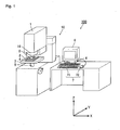
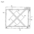
- the hardness tester 100 is, for example, a Vickers hardness tester and, as shown in Fig. 1 , includes a tester main body 10, a controller 6, an operator 7, a monitor 8, and the like.
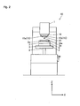
- the tester main body 10 includes, for example and as shown in Fig. 2 , a hardness measurer 1 performing a hardness measurement of a specimen S; a specimen stage 2 on which the specimen S is placed; an XY stage 3 displacing the specimen stage 2; an AF (Z) stage 4 for focusing on a surface of the specimen S; and a lift mechanism 5 lifting and lowering the specimen stage 2 (XY stage 3 and AF (Z) stage 4).
- the hardness measurer 1 for example, includes an illumination device 11 illuminating the surface of the specimen S; a CCD (Charge Coupled Device) camera 12 capturing an image of the surface of the specimen S; an indenter shaft 14 which includes an indenter 14a; and field lenses 15.
- the hardness measurer 1 is further configured with a turret 16, which is able to switch between the indenter shaft 14 and the field lenses 15 by rotating.
- the illumination device 11 illuminates the surface of the specimen S by irradiating light.
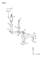
- the light irradiated from the illumination device 11 reaches the surface of the specimen S via a lens 1a, a half mirror 1d, a mirror 1e, and the field lenses 15.
- the CCD camera 12 is an image capturer. As shown in Fig. 3 , for example, the CCD camera 12 captures an image of the surface of the specimen S and of an indentation formed thereon by the indenter 14a based on reflected light input from the surface of the specimen S via the field lenses 15, the mirror 1e, the half mirror 1d, a mirror 1g, and a lens 1h. The CCD camera 12 then acquires image data and outputs the image data to the controller 6 via a frame grabber 17, which is capable of simultaneously accumulating and storing image data for a plurality of frames.
- the specimen S is placed on the specimen stage 2 and the indenter shaft 14 is displaced toward the specimen S by a loading mechanism (not shown in the drawings), which is driven in response to a control signal output by the controller 6.
- the indenter shaft 14 then presses the indenter 14a, which includes a tip portion, onto the surface of the specimen S with a predetermined testing force.
- the indenter 14a of the present embodiment has a tip having a quadrilateral spindle shape. Thus, in a plan view, a quadrilateral indentation is formed in the surface of the specimen S.
- the field lenses 15 are collective lenses configured with differing powers of magnification.
- a plurality of field lenses 15 are supported on a lower surface of the turret 16 and, by being disposed above the specimen S through rotation of the turret 16, light irradiated from the illumination device 11 is uniformly irradiated on the surface of the specimen S.
- the field lenses 15 are configured to include a high power field lens 15a and a low power field lens 15b having a magnification lower than the high power field lens 15a.
- the turret 16 includes on the lower surface thereof the indenter shaft 14 and the plurality of field lenses 15 (the high power field lens 15a and the low power field lens 15b). By rotating around an axis in the Z-axis direction, the turret 16 is configured to be capable of switching to one of the indenter shaft 14 and the plurality of field lenses 15 in order to position the same above the specimen S. That is, the turret 16 is capable of forming the indentation in the surface of the specimen S by lowering the indenter shaft 14 in a state where the indenter shaft 14 is positioned above the specimen S, and is further capable of observing the formed indentation by positioning the field lenses 15 above the specimen S.
- the specimen stage 2 includes a specimen holder 2a holding the specimen S which is placed on the top surface of the specimen stage 2.
- the XY stage 3 is driven by a driving mechanism (not shown in the drawings) driving the XY stage 3 in response to a control signal output by the controller 6.
- the specimen stage 2 is thus displaced in a direction (X direction or Y direction) perpendicular to a displacement direction (Z direction) of the indenter 14a.
- the AF stage 4 is driven in response to a control signal output by the controller 6 and, based on the image data captured by the CCD camera 12, minutely lifts and lowers the specimen stage 2 to focus on the surface of the specimen S.
- the lift mechanism 5 is driven in response to a control signal output by the controller 6 and changes the relative distance between the specimen stage 2 and the field lenses 15 by displacing the specimen stage 2 (the XY stage 3 and AF stage 4) in a vertical direction.
- the operator 7 is configured to include a keyboard 71, a mouse 72, and the like, and is employed, for example, when a user defines various conditions for execution of a hardness test with the hardness tester 100. Defining various conditions means, for example, setting test conditions (values such as material of the specimen S, a testing force (N) to be loaded on the specimen S by the indenter 14a, and magnification powers of the field lenses 15), a test start point, a number of rows/columns, pitch, and the like.
- test conditions values such as material of the specimen S, a testing force (N) to be loaded on the specimen S by the indenter 14a, and magnification powers of the field lenses 15
- the monitor 8 is a display and may be configured with a display device such as an LCD (Liquid Crystal Display).
- the monitor 8 displays an image captured by the CCD camera 12 of the surface of the specimen S and an image of the indentation formed thereon.
- the monitor 8 also displays defined conditions for the hardness test input with the operator 7, results of the hardness test, and the like.
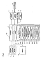
- the controller 6 is configured to include a CPU (Central Processing Unit) 61, a RAM (Random Access Memory) 62, a memory 63, and the like. By executing a predetermined program stored in the memory 63, the controller 6 can perform operation control for the performance of a predetermined hardness test, and the like.
- a CPU Central Processing Unit
- RAM Random Access Memory
- the CPU 61 reads a processing program, for example, stored in the memory 63, then performs overall control of the hardness tester 100 by loading and executing the processing program in the RAM 62.
- the RAM 62 loads the processing program executed by the CPU 61 in a program storage region within the RAM 62.
- the RAM 62 also stores in a data storage region input data and processing results generated when the processing program is executed.
- the memory 63 includes, for example, a storage medium (not shown in the drawings) configured with a semiconductor memory and the like for storing a program, data, and the like.
- the memory 63 stores various data, various processing programs, data processed by execution of the programs, and the like to enable the CPU 61 to perform overall control of the hardness tester 100.
- the memory 63 includes an image data memory 63a storing image data captured by the CCD camera 12 and a program memory 63b storing programs.
- Image data for the image of the indentation formed on the surface of the specimen S is stored in the image data memory 63a.
- An XY stage control program 631, an autofocus program 632, an indentation formation program 633, a clipping program 634, a display control program 635, and a hardness calculation program 636, for example, are stored in the program memory 63b.
- the XY stage control program 631 is a program that, for example, allows the CPU 61 to control a position of the XY stage 3 such that, after the specimen S is placed on the specimen stage 2, the specimen S and the CCD camera 12 are opposite each other. Specifically, by executing the XY stage control program 631, the CPU 61 displaces the XY stage 3 such that a predetermined region on the surface of the specimen S is directly below the CCD camera 12.
- the autofocus program 632 is a program that, for example, allows the CPU 61 to perform autofocusing with respect to the surface of the specimen S. Specifically, by executing the autofocus program 632, the CPU 61 lifts and lowers the AF stage 4 to perform autofocusing with respect to the surface of the specimen S based on image information obtained by the CCD camera 12 of the hardness measurer 1.
- the indentation formation program 633 is a program that, for example, allows the CPU 61 to form the indentation in the surface of the specimen S. Specifically, by executing the indentation formation program 633, the CPU 61 presses the indenter 14a onto the surface of the specimen S with the predetermined testing force to form the indentation. Furthermore, in the present embodiment, because the indentation is formed having a quadrilateral shape in a plan view, an image of the quadrilateral indentation is captured. The image of the formed indentation is captured by the CCD camera 12 and the image data for the captured image of the indentation is stored in the image data memory 63a.
- the clipping program 634 is a program that, for example, allows the CPU 61 to clip a plurality of regions that contain predetermined measurement points from the image of the indentation captured by the CCD camera 12.
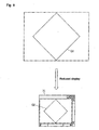
- Fig. 5 illustrates a conceptual diagram showing clipping regions of the captured image of the indentation.
- the CPU 61 clips four regions (clipping regions) R1 - R4 which contain vertices P1 - P4 of the image of the indentation as the predetermined measurement points.
- the position and shape of the clipping regions R1 - R4 are predefined according to the shape of the indenter used in the hardness tester.
- the present embodiment is a hardness tester in which an image of a quadrilateral indentation is captured. Therefore, four vertices of the indentation may be assumed to be positioned at central portions at each of a top and bottom portion of the captured image and at central portions at each of a left and right portion of the image. Three-sided clipping regions R1 and R3 are defined at the central portions at the top and bottom of the image, respectively, and five-sided clipping regions R2 and R4 are defined at the central portions at the left and right of the image, respectively.
- the CPU 61 acts as a clipper by executing this clipping program 634.
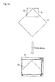
- the display control program 635 is a program that, for example, allows the CPU 61 to simultaneously display on the monitor 8 images of the plurality of regions (clipping regions R1 - R4) clipped by the execution of the clipping program 634. Specifically, as shown in Fig. 6 , by executing the display control program 635, the CPU 61 displays on the monitor images in which only the clipping regions R1 - R4 have been extracted from the image of the indentation.
- the CPU 61 is also able to display vertical guide lines L1 extending in the vertical direction and horizontal guide lines L2 extending in the horizontal direction overlaid on the images of the clipping regions R1 - R4 displayed on the monitor 8.
- the vertical guide lines L1 include a central vertical guide line L11 defined so as to travel through the center in a width direction of the monitor 8; a left vertical guide line L12 parallel to the central vertical guide line L11 and defined so as to be positioned near the vertex P2; and a right vertical guide line L13 parallel to the central vertical guide line L11 and defined so as to be positioned near the vertex P4.
- the horizontal guide lines L2 include a central horizontal guide line L21 defined so as to travel through the center in a height direction of the monitor 8; a top horizontal guide line L22 parallel to the central horizontal guide line L21 and defined so as to be positioned near the vertex P1; and a bottom horizontal guide line L23 parallel to the central horizontal guide line L21 and defined so as to be positioned near the vertex P3.
- the CPU 61 displays the guide lines L1 and L2. The user is able to align the positions of the vertices P1 and P3 and the positions of the vertices P2 and P4 using the guide lines L1 and L2.
- the CPU 61 acts as a display controller by executing this display control program 635.
- the hardness calculation program 636 is a program that, for example, allows the CPU 61 to measure the length of diagonal lines of the indentation from the image of the indentation and, based on the measured length of the diagonal lines of the indentation, to calculate hardness of the specimen S. Specifically, when the vertices P1 - P4 of the indentation are indicated as measurement points by the user, for example, the CPU 61 executes the hardness calculation program 636 and measures the length of the diagonal lines of the indentation. Of course, the CPU 61 includes the pixel count for portions of the image not displayed on the monitor 8 in the calculations, as well. At this point, since the four vertices P1 - P4 of the indentation are displayed on the monitor 8 simultaneously, the user is able to perform measurements of width and height while verifying the positions of the four vertices P1 - P4.
- the hardness tester 100 of the present embodiment is described.
- the plurality of clipping regions R1 - R4 which contain the predetermined measurement points (the vertices P1 - P4 of the image of the indentation) are clipped (see Fig. 5 ). Only the images of the clipping regions R1 - R4 are then displayed on the monitor 8 (see Fig. 6 ). Therefore, there is no need to display the entire image captured by the CCD camera 12 and regions other than the clipping regions R1 - R4 are not displayed.
- the images of the clipping regions R1 - R4 displayed on the monitor 8 are images in which portions containing effective measurement points (vertices P1 - P4) have been clipped from the image of the indentation. Vertices P1 - P4 of the image of the indentation can all be verified simultaneously on the monitor 8.
- the vertical guide lines L1 and the horizontal guide lines L2 can be displayed overlaid on the images. Therefore, the user can align the positions of opposing vertices (P1 with P3 and P2 with P4) and can perform measurements of the width and the height of the indentation while viewing the positions of the vertices P1 - P4.
- the hardness tester 100 of the present embodiment includes the CCD camera 12, the monitor 8, the clipper (the CPU 61 and the clipping program 634), and the display controller (the CPU 61 and the display control program 635).
- the CCD camera 12 captures an image of the indentation formed on the surface of the specimen S via the field lenses 15.
- the monitor 8 displays the image of the quadrilateral indentation captured by the CCD camera 12.
- the clipper (the CPU 61 and the clipping program 634) clips the plurality of regions R1 - R4 from the image of the indentation captured by the CCD camera 12, the regions R1 - R4 containing the vertices P1 - P4 of the image of the indentation as the predetermined measurement points.
- the display controller (the CPU 61 and the display control program 635) simultaneously displays on the monitor 8 the plurality of regions R1 - R4 clipped by the clipper. Therefore, the plurality of measurement points in the image (the vertices P1 - P4 of the image of the indentation) can be simultaneously displayed on the monitor 8 while preserving image resolution. Accordingly, a manual read process in which the measurement points are manually selected can be executed accurately.
- the display controller is able to display the vertical guide lines L1 extending in the vertical direction and the horizontal guide lines L2 extending in the horizontal direction by overlaying the guide lines L1 and L2 on the image on the monitor 8. Therefore, the positions of opposing vertices (P1 with P3 and P2 with P4) can be aligned and measurement of the width and height can be performed while viewing the positions of the four vertices P1 - P4 on the image.
- an evaluator (the CPU 61 and an evaluation program 637) may be further included, evaluating whether the predetermined measurement points (the vertices P1 - P4 of the image of the indentation) are contained in each of the plurality of clipped regions R1 - R4.
- the CPU 61 determines whether the vertices P1 - P4 of the image are contained by performing edge detection for each of the clipping regions R1 - R4. In this way, even in a case where the capture positions are misaligned, processing can be performed to quickly recapture the image and the like.
- the shape of the image of the indentation is not limited to this.
- the indenter is not limited to a quadrilateral spindle shape.
- the clipping regions may be defined according to a shape of an image of an indentation derived from the shape of an indenter. Further, in the above-described embodiment, a case where the clipping regions are defined with a three-sided shape and a five-sided shape was described as an example. However, the shape of the clipping regions is not limited to these.
Landscapes
- General Physics & Mathematics (AREA)
- Physics & Mathematics (AREA)
- Immunology (AREA)
- Pathology (AREA)
- Analytical Chemistry (AREA)
- Biochemistry (AREA)
- General Health & Medical Sciences (AREA)
- Life Sciences & Earth Sciences (AREA)
- Health & Medical Sciences (AREA)
- Chemical & Material Sciences (AREA)
- Engineering & Computer Science (AREA)
- Quality & Reliability (AREA)
- Computer Vision & Pattern Recognition (AREA)
- Theoretical Computer Science (AREA)
- Investigating Strength Of Materials By Application Of Mechanical Stress (AREA)
- Microscoopes, Condenser (AREA)
Applications Claiming Priority (1)
| Application Number | Priority Date | Filing Date | Title |
|---|---|---|---|
| JP2011188460A JP2013050379A (ja) | 2011-08-31 | 2011-08-31 | 硬さ試験機 |
Publications (3)
| Publication Number | Publication Date |
|---|---|
| EP2565618A2 true EP2565618A2 (de) | 2013-03-06 |
| EP2565618A3 EP2565618A3 (de) | 2017-03-01 |
| EP2565618B1 EP2565618B1 (de) | 2019-10-02 |
Family
ID=46982428
Family Applications (1)
| Application Number | Title | Priority Date | Filing Date |
|---|---|---|---|
| EP12182464.3A Active EP2565618B1 (de) | 2011-08-31 | 2012-08-30 | Härtetester |
Country Status (4)
| Country | Link |
|---|---|
| US (1) | US9032784B2 (de) |
| EP (1) | EP2565618B1 (de) |
| JP (1) | JP2013050379A (de) |
| CN (1) | CN102967516B (de) |
Cited By (2)
| Publication number | Priority date | Publication date | Assignee | Title |
|---|---|---|---|---|
| EP2784475A1 (de) * | 2013-03-28 | 2014-10-01 | Mitutoyo Corporation | Verfahren und Vorrichtung für Härteprüfer |
| DE102014104704B4 (de) * | 2013-04-10 | 2018-11-08 | EMCO-TEST Prüfmaschinen GmbH | Verfahren und Vorrichtung zur computerunterstützten Auswertung von Härteprüfungen eines Prüfkörpers |
Families Citing this family (9)
| Publication number | Priority date | Publication date | Assignee | Title |
|---|---|---|---|---|
| JP5977556B2 (ja) | 2012-03-27 | 2016-08-24 | 株式会社ミツトヨ | 硬さ試験機 |
| US20140267679A1 (en) * | 2013-03-13 | 2014-09-18 | Leco Corporation | Indentation hardness test system having an autolearning shading corrector |
| JP6277075B2 (ja) | 2014-07-16 | 2018-02-07 | 株式会社ミツトヨ | 硬さ試験機 |
| JP6721306B2 (ja) * | 2015-09-10 | 2020-07-15 | 株式会社ミツトヨ | 硬さ試験機 |
| JP6858038B2 (ja) * | 2017-03-08 | 2021-04-14 | 株式会社ミツトヨ | 硬さ試験機及びプログラム |
| DE102017107270A1 (de) * | 2017-04-05 | 2018-10-11 | Asmec Advanced Surface Mechanics Gmbh | Verfahren zur Analyse von Oberflächenmessungen |
| WO2019219455A1 (en) * | 2018-05-15 | 2019-11-21 | Struers ApS | Hardness determination |
| JP7144267B2 (ja) | 2018-10-03 | 2022-09-29 | 株式会社ミツトヨ | 硬さ試験機 |
| JP7141296B2 (ja) | 2018-10-03 | 2022-09-22 | 株式会社ミツトヨ | 硬さ試験機 |
Citations (1)
| Publication number | Priority date | Publication date | Assignee | Title |
|---|---|---|---|---|
| JP2003166923A (ja) | 2001-11-30 | 2003-06-13 | Akashi Corp | 硬さ試験機及び硬さ試験方法 |
Family Cites Families (19)
| Publication number | Priority date | Publication date | Assignee | Title |
|---|---|---|---|---|
| GB1563570A (en) * | 1976-08-19 | 1980-03-26 | Seiko Instr & Electronics | Hardness tester |
| GB1588248A (en) * | 1977-11-25 | 1981-04-23 | Vickers Ltd | Hardness testing apparatus |
| JPS5742838A (en) * | 1980-08-27 | 1982-03-10 | Komatsu Ltd | Microhardness meter |
| IT1179997B (it) * | 1984-02-24 | 1987-09-23 | Consiglio Nazionale Ricerche | Procedimento ed apparecchiatura per il rilievo dell impronta lasciata in un provino nella misura della durezza alla penetrazione |
| FR2619917A1 (fr) * | 1987-08-31 | 1989-03-03 | Armines | Procede et appareil de mesure des dimensions principales d'une empreinte d'indentation formee dans la surface d'une piece |
| JP2684384B2 (ja) * | 1988-01-29 | 1997-12-03 | 株式会社ロゼフテクノロジー | 硬度測定装置 |
| JP2731864B2 (ja) * | 1989-09-05 | 1998-03-25 | 新日本製鐵株式会社 | 押込型硬度計 |
| US5559937A (en) * | 1993-08-28 | 1996-09-24 | Namco Ltd. | Clipping processing device, three-dimensional simulator device, and clipping processing method |
| US6072497A (en) * | 1997-05-30 | 2000-06-06 | Hewlett-Packard Company | Volumetric pre-clipping method that guarantees minimal number of sample points through a volume |
| US6052128A (en) * | 1997-07-23 | 2000-04-18 | International Business Machines Corp. | Method and apparatus for clipping convex polygons on single instruction multiple data computers |
| CN1316417C (zh) * | 2002-10-18 | 2007-05-16 | 莱克公司 | 刻痕硬度测试系统 |
| US6996264B2 (en) * | 2002-10-18 | 2006-02-07 | Leco Corporation | Indentation hardness test system |
| US7121136B2 (en) * | 2002-12-25 | 2006-10-17 | Mitutoyo Corporation | Hardness testing apparatus |
| US8508550B1 (en) * | 2008-06-10 | 2013-08-13 | Pixar | Selective rendering of objects |
| JP5290864B2 (ja) * | 2009-05-18 | 2013-09-18 | キヤノン株式会社 | 位置姿勢推定装置及び方法 |
| US8401339B1 (en) * | 2010-01-06 | 2013-03-19 | Marseille Networks, Inc. | Apparatus for partitioning and processing a digital image using two or more defined regions |
| JP5567963B2 (ja) * | 2010-09-29 | 2014-08-06 | 富士フイルム株式会社 | 画像処理装置、放射線画像システム、画像処理方法およびプログラム |
| JP2012078306A (ja) | 2010-10-06 | 2012-04-19 | Mitsutoyo Corp | 硬さ試験機 |
| JP5501189B2 (ja) | 2010-10-06 | 2014-05-21 | 株式会社ミツトヨ | 硬さ試験機 |
-
2011
- 2011-08-31 JP JP2011188460A patent/JP2013050379A/ja active Pending
-
2012
- 2012-08-09 US US13/570,392 patent/US9032784B2/en active Active
- 2012-08-30 EP EP12182464.3A patent/EP2565618B1/de active Active
- 2012-08-31 CN CN201210320798.9A patent/CN102967516B/zh active Active
Patent Citations (1)
| Publication number | Priority date | Publication date | Assignee | Title |
|---|---|---|---|---|
| JP2003166923A (ja) | 2001-11-30 | 2003-06-13 | Akashi Corp | 硬さ試験機及び硬さ試験方法 |
Cited By (2)
| Publication number | Priority date | Publication date | Assignee | Title |
|---|---|---|---|---|
| EP2784475A1 (de) * | 2013-03-28 | 2014-10-01 | Mitutoyo Corporation | Verfahren und Vorrichtung für Härteprüfer |
| DE102014104704B4 (de) * | 2013-04-10 | 2018-11-08 | EMCO-TEST Prüfmaschinen GmbH | Verfahren und Vorrichtung zur computerunterstützten Auswertung von Härteprüfungen eines Prüfkörpers |
Also Published As
| Publication number | Publication date |
|---|---|
| JP2013050379A (ja) | 2013-03-14 |
| EP2565618B1 (de) | 2019-10-02 |
| CN102967516A (zh) | 2013-03-13 |
| US9032784B2 (en) | 2015-05-19 |
| CN102967516B (zh) | 2017-03-01 |
| US20130047713A1 (en) | 2013-02-28 |
| EP2565618A3 (de) | 2017-03-01 |
Similar Documents
| Publication | Publication Date | Title |
|---|---|---|
| US9032784B2 (en) | Hardness tester for maintaining image resolution by using image clipping | |
| US9442054B2 (en) | Hardness tester having offset correction feature | |
| EP2784475B1 (de) | Verfahren und Vorrichtung für Härteprüfer | |
| JP5501189B2 (ja) | 硬さ試験機 | |
| US9366609B2 (en) | Hardness tester and method for hardness test | |
| US8566735B2 (en) | Hardness tester with a user interface for setting test locations | |
| EP2543984B1 (de) | Härtetestverfahren | |
| JP6559023B2 (ja) | 硬さ試験機及び硬さ試験方法 | |
| EP2645079B1 (de) | Härtetester | |
| US20140177937A1 (en) | Hardness tester and method for hardness test | |
| US20130047712A1 (en) | Hardness tester | |
| JP5559587B2 (ja) | 硬さ試験機及び硬さ試験方法 | |
| JP5910407B2 (ja) | 硬さ試験機および硬さ試験機における硬さ試験方法 | |
| JP6560937B2 (ja) | 硬さ試験機及び硬さ試験方法 | |
| JP5065189B2 (ja) | オートフォーカス装置 | |
| JP6530287B2 (ja) | 硬さ試験機及び硬さ試験方法 | |
| JP6858038B2 (ja) | 硬さ試験機及びプログラム | |
| JP2002357524A (ja) | 硬度計 | |
| JP2008233041A (ja) | 硬さ試験機 |
Legal Events
| Date | Code | Title | Description |
|---|---|---|---|
| PUAI | Public reference made under article 153(3) epc to a published international application that has entered the european phase |
Free format text: ORIGINAL CODE: 0009012 |
|
| AK | Designated contracting states |
Kind code of ref document: A2 Designated state(s): AL AT BE BG CH CY CZ DE DK EE ES FI FR GB GR HR HU IE IS IT LI LT LU LV MC MK MT NL NO PL PT RO RS SE SI SK SM TR |
|
| AX | Request for extension of the european patent |
Extension state: BA ME |
|
| PUAL | Search report despatched |
Free format text: ORIGINAL CODE: 0009013 |
|
| AK | Designated contracting states |
Kind code of ref document: A3 Designated state(s): AL AT BE BG CH CY CZ DE DK EE ES FI FR GB GR HR HU IE IS IT LI LT LU LV MC MK MT NL NO PL PT RO RS SE SI SK SM TR |
|
| AX | Request for extension of the european patent |
Extension state: BA ME |
|
| RIC1 | Information provided on ipc code assigned before grant |
Ipc: G01N 3/06 20060101AFI20170124BHEP Ipc: G01N 3/42 20060101ALI20170124BHEP Ipc: G06T 15/30 20110101ALI20170124BHEP |
|
| STAA | Information on the status of an ep patent application or granted ep patent |
Free format text: STATUS: REQUEST FOR EXAMINATION WAS MADE |
|
| 17P | Request for examination filed |
Effective date: 20170503 |
|
| RBV | Designated contracting states (corrected) |
Designated state(s): AL AT BE BG CH CY CZ DE DK EE ES FI FR GB GR HR HU IE IS IT LI LT LU LV MC MK MT NL NO PL PT RO RS SE SI SK SM TR |
|
| STAA | Information on the status of an ep patent application or granted ep patent |
Free format text: STATUS: EXAMINATION IS IN PROGRESS |
|
| 17Q | First examination report despatched |
Effective date: 20181123 |
|
| GRAP | Despatch of communication of intention to grant a patent |
Free format text: ORIGINAL CODE: EPIDOSNIGR1 |
|
| STAA | Information on the status of an ep patent application or granted ep patent |
Free format text: STATUS: GRANT OF PATENT IS INTENDED |
|
| INTG | Intention to grant announced |
Effective date: 20190326 |
|
| GRAS | Grant fee paid |
Free format text: ORIGINAL CODE: EPIDOSNIGR3 |
|
| GRAA | (expected) grant |
Free format text: ORIGINAL CODE: 0009210 |
|
| STAA | Information on the status of an ep patent application or granted ep patent |
Free format text: STATUS: THE PATENT HAS BEEN GRANTED |
|
| AK | Designated contracting states |
Kind code of ref document: B1 Designated state(s): AL AT BE BG CH CY CZ DE DK EE ES FI FR GB GR HR HU IE IS IT LI LT LU LV MC MK MT NL NO PL PT RO RS SE SI SK SM TR |
|
| REG | Reference to a national code |
Ref country code: GB Ref legal event code: FG4D |
|
| REG | Reference to a national code |
Ref country code: CH Ref legal event code: EP Ref country code: AT Ref legal event code: REF Ref document number: 1186723 Country of ref document: AT Kind code of ref document: T Effective date: 20191015 |
|
| REG | Reference to a national code |
Ref country code: DE Ref legal event code: R096 Ref document number: 602012064470 Country of ref document: DE |
|
| REG | Reference to a national code |
Ref country code: IE Ref legal event code: FG4D |
|
| REG | Reference to a national code |
Ref country code: NL Ref legal event code: MP Effective date: 20191002 |
|
| REG | Reference to a national code |
Ref country code: LT Ref legal event code: MG4D |
|
| REG | Reference to a national code |
Ref country code: AT Ref legal event code: MK05 Ref document number: 1186723 Country of ref document: AT Kind code of ref document: T Effective date: 20191002 |
|
| PG25 | Lapsed in a contracting state [announced via postgrant information from national office to epo] |
Ref country code: FI Free format text: LAPSE BECAUSE OF FAILURE TO SUBMIT A TRANSLATION OF THE DESCRIPTION OR TO PAY THE FEE WITHIN THE PRESCRIBED TIME-LIMIT Effective date: 20191002 Ref country code: BG Free format text: LAPSE BECAUSE OF FAILURE TO SUBMIT A TRANSLATION OF THE DESCRIPTION OR TO PAY THE FEE WITHIN THE PRESCRIBED TIME-LIMIT Effective date: 20200102 Ref country code: PT Free format text: LAPSE BECAUSE OF FAILURE TO SUBMIT A TRANSLATION OF THE DESCRIPTION OR TO PAY THE FEE WITHIN THE PRESCRIBED TIME-LIMIT Effective date: 20200203 Ref country code: PL Free format text: LAPSE BECAUSE OF FAILURE TO SUBMIT A TRANSLATION OF THE DESCRIPTION OR TO PAY THE FEE WITHIN THE PRESCRIBED TIME-LIMIT Effective date: 20191002 Ref country code: NL Free format text: LAPSE BECAUSE OF FAILURE TO SUBMIT A TRANSLATION OF THE DESCRIPTION OR TO PAY THE FEE WITHIN THE PRESCRIBED TIME-LIMIT Effective date: 20191002 Ref country code: NO Free format text: LAPSE BECAUSE OF FAILURE TO SUBMIT A TRANSLATION OF THE DESCRIPTION OR TO PAY THE FEE WITHIN THE PRESCRIBED TIME-LIMIT Effective date: 20200102 Ref country code: AT Free format text: LAPSE BECAUSE OF FAILURE TO SUBMIT A TRANSLATION OF THE DESCRIPTION OR TO PAY THE FEE WITHIN THE PRESCRIBED TIME-LIMIT Effective date: 20191002 Ref country code: LV Free format text: LAPSE BECAUSE OF FAILURE TO SUBMIT A TRANSLATION OF THE DESCRIPTION OR TO PAY THE FEE WITHIN THE PRESCRIBED TIME-LIMIT Effective date: 20191002 Ref country code: SE Free format text: LAPSE BECAUSE OF FAILURE TO SUBMIT A TRANSLATION OF THE DESCRIPTION OR TO PAY THE FEE WITHIN THE PRESCRIBED TIME-LIMIT Effective date: 20191002 Ref country code: ES Free format text: LAPSE BECAUSE OF FAILURE TO SUBMIT A TRANSLATION OF THE DESCRIPTION OR TO PAY THE FEE WITHIN THE PRESCRIBED TIME-LIMIT Effective date: 20191002 Ref country code: GR Free format text: LAPSE BECAUSE OF FAILURE TO SUBMIT A TRANSLATION OF THE DESCRIPTION OR TO PAY THE FEE WITHIN THE PRESCRIBED TIME-LIMIT Effective date: 20200103 Ref country code: LT Free format text: LAPSE BECAUSE OF FAILURE TO SUBMIT A TRANSLATION OF THE DESCRIPTION OR TO PAY THE FEE WITHIN THE PRESCRIBED TIME-LIMIT Effective date: 20191002 |
|
| PG25 | Lapsed in a contracting state [announced via postgrant information from national office to epo] |
Ref country code: CZ Free format text: LAPSE BECAUSE OF FAILURE TO SUBMIT A TRANSLATION OF THE DESCRIPTION OR TO PAY THE FEE WITHIN THE PRESCRIBED TIME-LIMIT Effective date: 20191002 Ref country code: HR Free format text: LAPSE BECAUSE OF FAILURE TO SUBMIT A TRANSLATION OF THE DESCRIPTION OR TO PAY THE FEE WITHIN THE PRESCRIBED TIME-LIMIT Effective date: 20191002 Ref country code: IS Free format text: LAPSE BECAUSE OF FAILURE TO SUBMIT A TRANSLATION OF THE DESCRIPTION OR TO PAY THE FEE WITHIN THE PRESCRIBED TIME-LIMIT Effective date: 20200224 Ref country code: RS Free format text: LAPSE BECAUSE OF FAILURE TO SUBMIT A TRANSLATION OF THE DESCRIPTION OR TO PAY THE FEE WITHIN THE PRESCRIBED TIME-LIMIT Effective date: 20191002 |
|
| PG25 | Lapsed in a contracting state [announced via postgrant information from national office to epo] |
Ref country code: AL Free format text: LAPSE BECAUSE OF FAILURE TO SUBMIT A TRANSLATION OF THE DESCRIPTION OR TO PAY THE FEE WITHIN THE PRESCRIBED TIME-LIMIT Effective date: 20191002 |
|
| REG | Reference to a national code |
Ref country code: DE Ref legal event code: R097 Ref document number: 602012064470 Country of ref document: DE |
|
| PG2D | Information on lapse in contracting state deleted |
Ref country code: IS |
|
| PG25 | Lapsed in a contracting state [announced via postgrant information from national office to epo] |
Ref country code: EE Free format text: LAPSE BECAUSE OF FAILURE TO SUBMIT A TRANSLATION OF THE DESCRIPTION OR TO PAY THE FEE WITHIN THE PRESCRIBED TIME-LIMIT Effective date: 20191002 Ref country code: DK Free format text: LAPSE BECAUSE OF FAILURE TO SUBMIT A TRANSLATION OF THE DESCRIPTION OR TO PAY THE FEE WITHIN THE PRESCRIBED TIME-LIMIT Effective date: 20191002 Ref country code: RO Free format text: LAPSE BECAUSE OF FAILURE TO SUBMIT A TRANSLATION OF THE DESCRIPTION OR TO PAY THE FEE WITHIN THE PRESCRIBED TIME-LIMIT Effective date: 20191002 Ref country code: IS Free format text: LAPSE BECAUSE OF FAILURE TO SUBMIT A TRANSLATION OF THE DESCRIPTION OR TO PAY THE FEE WITHIN THE PRESCRIBED TIME-LIMIT Effective date: 20200202 |
|
| PLBE | No opposition filed within time limit |
Free format text: ORIGINAL CODE: 0009261 |
|
| STAA | Information on the status of an ep patent application or granted ep patent |
Free format text: STATUS: NO OPPOSITION FILED WITHIN TIME LIMIT |
|
| PG25 | Lapsed in a contracting state [announced via postgrant information from national office to epo] |
Ref country code: SM Free format text: LAPSE BECAUSE OF FAILURE TO SUBMIT A TRANSLATION OF THE DESCRIPTION OR TO PAY THE FEE WITHIN THE PRESCRIBED TIME-LIMIT Effective date: 20191002 Ref country code: IT Free format text: LAPSE BECAUSE OF FAILURE TO SUBMIT A TRANSLATION OF THE DESCRIPTION OR TO PAY THE FEE WITHIN THE PRESCRIBED TIME-LIMIT Effective date: 20191002 Ref country code: SK Free format text: LAPSE BECAUSE OF FAILURE TO SUBMIT A TRANSLATION OF THE DESCRIPTION OR TO PAY THE FEE WITHIN THE PRESCRIBED TIME-LIMIT Effective date: 20191002 |
|
| 26N | No opposition filed |
Effective date: 20200703 |
|
| PG25 | Lapsed in a contracting state [announced via postgrant information from national office to epo] |
Ref country code: SI Free format text: LAPSE BECAUSE OF FAILURE TO SUBMIT A TRANSLATION OF THE DESCRIPTION OR TO PAY THE FEE WITHIN THE PRESCRIBED TIME-LIMIT Effective date: 20191002 |
|
| PG25 | Lapsed in a contracting state [announced via postgrant information from national office to epo] |
Ref country code: MC Free format text: LAPSE BECAUSE OF FAILURE TO SUBMIT A TRANSLATION OF THE DESCRIPTION OR TO PAY THE FEE WITHIN THE PRESCRIBED TIME-LIMIT Effective date: 20191002 |
|
| REG | Reference to a national code |
Ref country code: CH Ref legal event code: PL |
|
| GBPC | Gb: european patent ceased through non-payment of renewal fee |
Effective date: 20200830 |
|
| PG25 | Lapsed in a contracting state [announced via postgrant information from national office to epo] |
Ref country code: LU Free format text: LAPSE BECAUSE OF NON-PAYMENT OF DUE FEES Effective date: 20200830 Ref country code: CH Free format text: LAPSE BECAUSE OF NON-PAYMENT OF DUE FEES Effective date: 20200831 Ref country code: LI Free format text: LAPSE BECAUSE OF NON-PAYMENT OF DUE FEES Effective date: 20200831 |
|
| REG | Reference to a national code |
Ref country code: BE Ref legal event code: MM Effective date: 20200831 |
|
| PG25 | Lapsed in a contracting state [announced via postgrant information from national office to epo] |
Ref country code: FR Free format text: LAPSE BECAUSE OF NON-PAYMENT OF DUE FEES Effective date: 20200831 |
|
| PG25 | Lapsed in a contracting state [announced via postgrant information from national office to epo] |
Ref country code: BE Free format text: LAPSE BECAUSE OF NON-PAYMENT OF DUE FEES Effective date: 20200831 Ref country code: GB Free format text: LAPSE BECAUSE OF NON-PAYMENT OF DUE FEES Effective date: 20200830 Ref country code: IE Free format text: LAPSE BECAUSE OF NON-PAYMENT OF DUE FEES Effective date: 20200830 |
|
| PG25 | Lapsed in a contracting state [announced via postgrant information from national office to epo] |
Ref country code: TR Free format text: LAPSE BECAUSE OF FAILURE TO SUBMIT A TRANSLATION OF THE DESCRIPTION OR TO PAY THE FEE WITHIN THE PRESCRIBED TIME-LIMIT Effective date: 20191002 Ref country code: MT Free format text: LAPSE BECAUSE OF FAILURE TO SUBMIT A TRANSLATION OF THE DESCRIPTION OR TO PAY THE FEE WITHIN THE PRESCRIBED TIME-LIMIT Effective date: 20191002 Ref country code: CY Free format text: LAPSE BECAUSE OF FAILURE TO SUBMIT A TRANSLATION OF THE DESCRIPTION OR TO PAY THE FEE WITHIN THE PRESCRIBED TIME-LIMIT Effective date: 20191002 |
|
| PG25 | Lapsed in a contracting state [announced via postgrant information from national office to epo] |
Ref country code: MK Free format text: LAPSE BECAUSE OF FAILURE TO SUBMIT A TRANSLATION OF THE DESCRIPTION OR TO PAY THE FEE WITHIN THE PRESCRIBED TIME-LIMIT Effective date: 20191002 |
|
| PGFP | Annual fee paid to national office [announced via postgrant information from national office to epo] |
Ref country code: DE Payment date: 20250820 Year of fee payment: 14 |