EP2565595B1 - Schwimmkörper zur Anzeige eines Füllstandes - Google Patents
Schwimmkörper zur Anzeige eines Füllstandes Download PDFInfo
- Publication number
- EP2565595B1 EP2565595B1 EP12001961.7A EP12001961A EP2565595B1 EP 2565595 B1 EP2565595 B1 EP 2565595B1 EP 12001961 A EP12001961 A EP 12001961A EP 2565595 B1 EP2565595 B1 EP 2565595B1
- Authority
- EP
- European Patent Office
- Prior art keywords
- float
- container
- attenuation structure
- field attenuation
- reflector
- Prior art date
- Legal status (The legal status is an assumption and is not a legal conclusion. Google has not performed a legal analysis and makes no representation as to the accuracy of the status listed.)
- Not-in-force
Links
- 239000003989 dielectric material Substances 0.000 claims description 8
- 230000005670 electromagnetic radiation Effects 0.000 claims description 2
- 230000002238 attenuated effect Effects 0.000 claims 1
- 230000003313 weakening effect Effects 0.000 description 34
- 238000005259 measurement Methods 0.000 description 5
- 238000013016 damping Methods 0.000 description 4
- 238000000034 method Methods 0.000 description 4
- 230000009466 transformation Effects 0.000 description 3
- 230000002411 adverse Effects 0.000 description 2
- 238000005253 cladding Methods 0.000 description 2
- 230000001419 dependent effect Effects 0.000 description 2
- 239000000463 material Substances 0.000 description 2
- 230000001133 acceleration Effects 0.000 description 1
- 230000015572 biosynthetic process Effects 0.000 description 1
- 238000005260 corrosion Methods 0.000 description 1
- 230000007797 corrosion Effects 0.000 description 1
- 230000001066 destructive effect Effects 0.000 description 1
- 230000001627 detrimental effect Effects 0.000 description 1
- 230000005672 electromagnetic field Effects 0.000 description 1
- 238000004880 explosion Methods 0.000 description 1
- 230000003993 interaction Effects 0.000 description 1
- 230000035699 permeability Effects 0.000 description 1
- 230000000704 physical effect Effects 0.000 description 1
Images



Classifications
-
- G—PHYSICS
- G01—MEASURING; TESTING
- G01F—MEASURING VOLUME, VOLUME FLOW, MASS FLOW OR LIQUID LEVEL; METERING BY VOLUME
- G01F23/00—Indicating or measuring liquid level or level of fluent solid material, e.g. indicating in terms of volume or indicating by means of an alarm
- G01F23/30—Indicating or measuring liquid level or level of fluent solid material, e.g. indicating in terms of volume or indicating by means of an alarm by floats
- G01F23/76—Indicating or measuring liquid level or level of fluent solid material, e.g. indicating in terms of volume or indicating by means of an alarm by floats characterised by the construction of the float
-
- G—PHYSICS
- G01—MEASURING; TESTING
- G01F—MEASURING VOLUME, VOLUME FLOW, MASS FLOW OR LIQUID LEVEL; METERING BY VOLUME
- G01F23/00—Indicating or measuring liquid level or level of fluent solid material, e.g. indicating in terms of volume or indicating by means of an alarm
- G01F23/22—Indicating or measuring liquid level or level of fluent solid material, e.g. indicating in terms of volume or indicating by means of an alarm by measuring physical variables, other than linear dimensions, pressure or weight, dependent on the level to be measured, e.g. by difference of heat transfer of steam or water
- G01F23/28—Indicating or measuring liquid level or level of fluent solid material, e.g. indicating in terms of volume or indicating by means of an alarm by measuring physical variables, other than linear dimensions, pressure or weight, dependent on the level to be measured, e.g. by difference of heat transfer of steam or water by measuring the variations of parameters of electromagnetic or acoustic waves applied directly to the liquid or fluent solid material
- G01F23/284—Electromagnetic waves
-
- G—PHYSICS
- G01—MEASURING; TESTING
- G01F—MEASURING VOLUME, VOLUME FLOW, MASS FLOW OR LIQUID LEVEL; METERING BY VOLUME
- G01F23/00—Indicating or measuring liquid level or level of fluent solid material, e.g. indicating in terms of volume or indicating by means of an alarm
- G01F23/30—Indicating or measuring liquid level or level of fluent solid material, e.g. indicating in terms of volume or indicating by means of an alarm by floats
- G01F23/64—Indicating or measuring liquid level or level of fluent solid material, e.g. indicating in terms of volume or indicating by means of an alarm by floats of the free float type without mechanical transmission elements
- G01F23/68—Indicating or measuring liquid level or level of fluent solid material, e.g. indicating in terms of volume or indicating by means of an alarm by floats of the free float type without mechanical transmission elements using electrically actuated indicating means
-
- G—PHYSICS
- G01—MEASURING; TESTING
- G01F—MEASURING VOLUME, VOLUME FLOW, MASS FLOW OR LIQUID LEVEL; METERING BY VOLUME
- G01F23/00—Indicating or measuring liquid level or level of fluent solid material, e.g. indicating in terms of volume or indicating by means of an alarm
- G01F23/30—Indicating or measuring liquid level or level of fluent solid material, e.g. indicating in terms of volume or indicating by means of an alarm by floats
- G01F23/64—Indicating or measuring liquid level or level of fluent solid material, e.g. indicating in terms of volume or indicating by means of an alarm by floats of the free float type without mechanical transmission elements
- G01F23/72—Indicating or measuring liquid level or level of fluent solid material, e.g. indicating in terms of volume or indicating by means of an alarm by floats of the free float type without mechanical transmission elements using magnetically actuated indicating means
Definitions
- the invention relates to a float for indicating the level of a medium in a container, wherein the float is guided under normal use of the wall of the container and is adapted to reflect emitted by a transmitter electromagnetic waves toward a receiver.
- the float when used as intended, at least the side of the floating body facing the transmitter is designed as a reflector for reflecting the electromagnetic waves onto the receiver.
- Such floats are used in practice to bring about a defined reflection behavior in the region of the surface of the medium in the region of the surface of the medium to be detected by metrology in level measurements based on the radar principle.
- the reflectance of electromagnetic waves at interfaces - at least also - depends on the refractive indices of the media forming the interface and thus on their permeability and permittivity numbers.
- the amplitude of the electromagnetic waves reflected without floating body is therefore dependent on the material properties of the media involved and thus dependent on the particular concrete use of a level measuring device.
- the ratio of useful to noise signal strength is practically unpredictable when the media boundary is used exclusively as the reflection surface, and accordingly the design of a fill level measuring device is correspondingly problematic. This problem is mitigated by the use of the aforementioned floating body, as the reflection of electromagnetic waves defined on generic floats and in particular is better than the reflection of media of low permittivity.
- the electromagnetic waves emitted by the transmitter, which is usually located above the medium, towards the medium are reflected by the floating body, which partially protrudes from the medium, and the reflected waves are also emitted by the receiver, which is also usually above Medium is received.
- the level is calculated by one of the known radar methods. At one of these Method, the level of the duration of an electromagnetic pulse is determined.
- the frequency of a continuous electromagnetic signal is modulated so that the level of the frequency difference between transmitted and received frequency can be determined (modulated continuous wave method).
- the float is in a reference container, which is usually an elongate hollow body of relatively small cross-sectional area, the wall of the reference container guiding the float.
- the reference container is usually located in the container or laterally adjacent to the container in which the medium is to be determined, and the longitudinal axis of the reference container is oriented substantially in the direction of gravitational acceleration.
- the reference container is connected to the container such that the level of the medium in the reference container coincides with the level of the medium in the container. Due to the small cross-sectional area of the hollow body and by the mass of the float disturbances of the rest of the medium, as they occur during the supply and discharge of the medium, is reduced and in this way the measurement accuracy is increased.
- the reference container At the upper end of the reference container are usually both the transmitter and the receiver for the electromagnetic waves and the reference container is often used as a waveguide for the electromagnetic waves.
- the floats are equipped with a magnet system, and laterally next to the reference container is also a display device for the level by means of magnetic valves or by means of a follower magnet. The display of the level is then made by two independent systems and increased by redundancy, the reliability, but it does not matter in the present case.
- Floats known in the prior art have a surface on which the electromagnetic wave is reflected.
- the basically required play of the floating body in the guide through the wall of the container causes an unpredictable tilting of the float, whereby the reflection properties are changed. This can lead to unpredictable reflections of the electromagnetic waves in the resulting by the tilting gap between the wall of the container and the float, which adversely affect the measurement.
- a generic floating body shows the published patent application WO 2008/086543 A2 ,
- the float consists of three interconnected balls and two flat discs at the outer ends.
- One disc has a reflective surface and the other disc stabilizes the float.
- a floating body of a level gauge in which the electromagnetic signals are guided along a cable or cable, describes the published patent application US 2005/0241391 A1 ,
- the floating body is designed to be movable along the rope and has at one end a reflecting the microwave signals disc.
- JP 62 039801 A and JP 63 204222 A take the use of layers whose thickness is ⁇ / 4 or ⁇ / 2. Where ⁇ is the wavelength of the light for which the mirrors are used.
- the object of the present invention is to provide a floating body having improved reflection characteristics for the electromagnetic waves, in particular regardless of whether the floating body is tilted or not, and which is preferably compatible with existing equipped with magnetic systems floats.
- the floating body according to the invention in which the previously derived and indicated object is achieved, is initially and essentially characterized in that, when used properly from the transmitter's point of view, a field weakening structure is formed behind the reflector such that the field strength in the region of the field weakening structure is opposite to the situation is weakened, in which the field weakening structure is not provided.
- the field weakening structure is implemented as a ⁇ / 4 filter and consists of alternating successively arranged large slices and small slices. It is initially irrelevant, by which physical effect such a field weakening is effected, whether this is achieved, for example, by a transformation of the field state and / or whether this is done by attenuation of passed in the field weakening structure electromagnetic waves.
- the use of the floating body according to the invention with trained reflection and field weakening structures instead of the floating bodies known from the prior art has the advantage of improved and substantially independent of the tilting of the floating body reflection properties.
- the side of the float facing the transmitter and designed as a reflector for reflection of the electromagnetic waves on the receiver generates the actual useful signal, which is to be used for distance and thus level determination.
- All components of the float should preferably be made of such materials that are, inter alia, resistant to the media, whose level is measured in the container, and have good reflection properties for electromagnetic waves.
- the density of the floating body in its entirety must be lower than that of the media whose level in the container is to be measured.
- the reflection properties are optimized by a view of the transmitter of the electromagnetic waves level or curved configuration of the surface of the reflector.
- the floating body consists of a buoyant body and an adjoining field weakening structure.
- the dimensions of buoyancy body and field weakening structure are chosen so that when tilting the float in the container only the buoyant body touches the wall of the container, the field weakening structure, however, the wall of the container is not affected. In this way, electrical charges are dissipated, whereby a risk of explosion in flammable media is avoided.
- the field weakening structure is implemented as a ⁇ / 4 filter ( ⁇ is the wavelength of the electromagnetic waves used), in which field weakening is brought about by destructive superimposition of the electromagnetic waves reaching the region of the field weakening structure.
- ⁇ is the wavelength of the electromagnetic waves used
- Such a ⁇ / 4 filter transforms the field state in the gap between the reflector and the field weakening structure on the one hand and the wall of the container on the other hand such that a large part of the electromagnetic wave is reflected;
- no energy is "lost”
- no electromagnetic field is muted in the classical sense.
- the designed as a ⁇ / 4 filter field weakening effectively acts as a reflector, it results at the top of the reflector almost complete reflection, as they would result in a "short circuit" with a completely closed metallic wall.
- the disks as seen in the wave propagation direction, in one embodiment, have a magnitude of approximately an odd multiple of a quarter of the wavelength of the electromagnetic waves used.
- the floating body consists of a field weakening structure and a reflector, wherein the field weakening structure also takes over the task of the buoyant body.
- a separate buoyancy body is eliminated.
- Such a float is very compact and tends to be less dumped than a floating body with a "patched" field weakening structure.
- At least one of the small disks is surrounded by at least one ring of at least one dielectric material.
- a ring influences the interaction of the electromagnetic wave with the field weakening structure in an advantageous manner, since the waveguide can be influenced in a targeted manner in and in the field weakening structure by means of the further boundary surface.
- the reflector and the field weakening structure are enveloped by a dielectric material.
- This cladding advantageously influences the reflection and the damping of the electromagnetic wave, and furthermore such a cladding can also be designed as corrosion protection.
- a further advantage is that a field weakening structure having a fissured geometry can be provided with a smoother contour, which is u. a. to effectively prevent the unwanted adhesion of the medium to the float.
- the expansion of the discs is not circular, whereby the reflection and damping properties of the Float for the electromagnetic waves, for example, to the geometry of the container can be adjusted.
- Fig. 1 is a typical application for a known from the prior art floating body 1, with the help of the level of a container 2, 4 located in a medium 3 is to be determined.
- a reference container 4 is connected to the container 2 such that the level of the medium 3 in the container 2 corresponds to the level of the medium 3 in the reference container 4.
- the float 4 is through the wall of the reference container 4 guided laterally so that it can move only in the direction of the longitudinal axis of the reference container 4.
- a fill level measuring device 5, 6 working with electromagnetic waves according to the radar principle has a transmitter 5 and a receiver 6 for electromagnetic waves and emits electromagnetic waves which propagate substantially along the longitudinal axis of the reference container 4 in the direction of the floating body 1.
- the reference container 4 represents a waveguide for the electromagnetic waves.
- the required circumferential gap between the float 1 and the wall of the reference container 1 has undesirable properties, it favors the formation of Störreflexionen that are detrimental to a precise level measurement.
- Asymmetries in the mentioned gap due to the unavoidable and unpredictable tilting of the floating body 1 in the reference container 4, asymmetries in the mentioned gap, which likewise adversely affect the reflected electromagnetic wave.
- the reflection properties by field transformation compared to in Fig. 1 illustrated prior art significantly improved.
- FIG. 2a, 2b and 3a illustrated embodiment of the floating body 1 according to the invention consists of a cylindrical buoyancy body 7, in which, however, the edges present in an ideal cylinder are blunted.
- the buoyant body 7 is adapted to the required gap to the inner diameter of the reference container 4.
- a field weakening structure 8 adjoins the part of the buoyant body 7 protruding from the medium 3.
- the buoyancy body 7 is formed as a known from the prior art float, with one here not shown magnet system is equipped. Therefore, the floating body 1 according to the invention can be equipped with an existing magnetic systems, whereby it is compatible with existing level measurement systems, which indicate the level, for example, by magnetic valves or a follower magnet.
- the field weakening structure 8 consists of concentric to the longitudinal axis of the buoyant body 7 discs 9, 10, 11, 12 with a sequence from the viewpoint of the level gauge 5 of a large diameter disc 9, a small diameter disc 10, a large diameter disc 11 and a Disc 12 with a small diameter, that is, two discs 10, 12 with a small diameter and two discs 9, 11 with a large diameter.
- the diameter of the large disks 9, 11 is significantly larger than that of the small disks 10, 12.
- the thickness of each of the disks 9 - 12 is substantially one quarter of the wavelength of the electromagnetic waves used, in other embodiments not shown here is the Thickness of each of the slices substantially an odd multiple of a quarter of the wavelength of the electromagnetic waves used.
- the disks 9-12 together with the part of the surface of the buoyant body 7 form a ⁇ / 4 filter, which is aligned substantially parallel to the flat surfaces of the disks 9-12.
- the thickness of the disc 12 is substantially greater than a quarter of the wavelength, whereby only the discs 9-11 form a ⁇ / 4 filter.
- the flat surface of the large disk 9, which lies closest to the level gauge 5, 6, forms the reflector 20 for the electromagnetic waves emitted by the transmitter of the level gauge.
- the float 1 is tilted in the reference container 4.
- the diameters of the discs 9-12 are chosen such that none of the discs 9-12 can come into contact with the reference container.
- the reflection properties of the float 1 according to the invention are better both in the tilted and non-tilted state than in prior art floats, but above all the reflection properties of the float 1 according to the invention are both in the tilted and non-tilted states practically consistently good.
- the field weakening structure 8 as a ⁇ / 4 filter, a larger proportion of the radiated power is reflected again, the proportion of the reflected electromagnetic radiation in relation to the total radiated energy is significantly greater than in the case of the design of the field weakening structure as a pure damping structure. Although in the latter case, the signal / noise ratio is improved, but the actual useful signal is not increased.
- a buoyant body 7 is guided with a round cross section through the wall of a reference container 1 with rectangular cross section, the geometries of the discs 9, 10 of the field weakening structure 8 perpendicular to the longitudinal axis of the reference container 4 are also rectangular.
- the level measuring device 5, 6 closer flat surface of the buoyant body 7 part of the field weakening structure 8 and the edge of the surface is not truncated, whereby the damping properties are changed.
- the attached to the buoyant body 7 field weakening structure 8 is different from that in the Fig. 2a, 2b and 3a shown embodiment of three discs 10, 12, 14 with a small diameter and three discs 9, 11, 13 with a large diameter.
- Each of the small disks 10, 12, 14 is in each case surrounded by a ring 15, 16, 17 of a different dielectric material, the outer diameter of which substantially corresponds to the diameter of the large disks 9, 11, 13.
- the large-diameter disk 9 closest to the level gauge 5, 6 is domed and the entire attached field weakening structure 8 is covered with a dielectric material 18.
- the float 1 from a field weakening structure 8 which also takes over the functionality of the buoyant body 7 at the same time.
- the field weakening structure 8 is laterally covered with a dielectric material 18.
Landscapes
- Physics & Mathematics (AREA)
- Fluid Mechanics (AREA)
- General Physics & Mathematics (AREA)
- Electromagnetism (AREA)
- Thermal Sciences (AREA)
- Level Indicators Using A Float (AREA)
- Measurement Of Levels Of Liquids Or Fluent Solid Materials (AREA)
Description
- Die Erfindung betrifft einen Schwimmkörper zur Anzeige des Füllstandes eines Mediums in einem Behälter, wobei der Schwimmkörper bei bestimmungsgemäßem Einsatz von der Wandung des Behälters geführt wird und dazu geeignet ist, von einem Sender emittierte elektromagnetische Wellen in Richtung auf einen Empfänger zu reflektieren. Dabei ist bei bestimmungsgemäßem Einsatz zumindest die dem Sender zugewandte Seite des Schwimmkörpers als Reflektor zur Reflexion der elektromagnetischen Wellen auf den Empfänger ausgebildet.
- Derartige Schwimmkörper werden in der Praxis eingesetzt, um bei auf dem Radarprinzip beruhenden Füllstandsmessungen ein definiertes Reflexionsverhalten im Bereich der Oberfläche des Mediums herbeizuführen, dessen Füllstand messtechnisch erfasst werden soll. Bekanntlich hängt der Reflexionsgrad elektromagnetischer Wellen an Grenzflächen - jedenfalls auch - ab von den Brechungsindizes der die Grenzfläche bildenden Medien und damit von deren Permeabilitäts- und Permittivitätszahlen. Die Amplitude der ohne Schwimmkörper reflektierten elektromagnetischen Wellen ist daher abhängig von den Materialeigenschaften der beteiligten Medien und damit abhängig von der jeweiligen konkreten Verwendung einer Füllstandsmessvorrichtung. Insbesondere ist bei ausschließlicher Nutzung der Mediumsgrenze als Reflexionsfläche praktisch nicht vorhersehbar das Verhältnis von Nutz- zu Störsignalstärke, entsprechend problematisch ist dann die Auslegung einer Füllstandmessvorrichtung. Diese Problematik wird durch den Einsatz der zuvor genannten Schwimmkörper gemildert, da die Reflexion von elektromagnetischen Wellen an gattungsgemäßen Schwimmkörpern definiert und insbesondere besser ist als die Reflexion an Medien geringer Permittivität.
- Die von dem Sender, der sich üblicherweise oberhalb des Mediums befindet, in Richtung auf das Medium ausgesandten elektromagnetischen Wellen werden von dem Schwimmkörper, der teilweise aus dem Medium ragt, reflektiert, und die reflektierten Wellen werden von dem Empfänger, der sich ebenfalls üblicherweise oberhalb des Mediums befindet, empfangen. Letztlich wird der Füllstand nach einem der bekannten Radarverfahren berechnet. Bei einem dieser Verfahren wird der Füllstand aus der Laufzeit eines elektromagnetischen Pulses bestimmt. Bei einem anderen Verfahren wird die Frequenz eines kontinuierlichen elektromagnetischen Signals so moduliert, dass der Füllstand aus dem Frequenzunterschied zwischen gesendeter und empfangener Frequenz bestimmt werden kann (moduliertes Dauerstrichverfahren).
- Oftmals befindet sich der Schwimmkörper in einem Referenzbehälter, der für gewöhnlich ein länglicher Hohlkörper mit verhältnismäßig geringer Querschnittsfläche ist, wobei die Wandung des Referenzbehälters den Schwimmkörper führt. Der Referenzbehälter befindet sich üblicherweise im Behälter oder seitlich neben dem Behälter, in dem sich das Medium befindet, dessen Füllstand zu bestimmen ist, und die Längsachse des Referenzbehälters ist im Wesentlichen in Richtung der Erdschwerebeschleunigung ausgerichtet. Der Referenzbehälter ist derart mit dem Behälter verbunden, dass der Füllstand des Mediums im Referenzbehälter mit dem Füllstand des Mediums im Behälter übereinstimmt. Durch die geringe Querschnittsfläche des Hohlkörpers und durch die Masse des Schwimmkörpers werden Störungen der Ruhe des Mediums, wie sie beim Zu- und Abführen des Mediums auftreten, verringert und wird auf diese Weise die Messgenauigkeit erhöht. Am oberen Ende des Referenzbehälters befinden sich üblicherweise sowohl der Sender als auch der Empfänger für die elektromagnetischen Wellen und der Referenzbehälter wird häufig als Hohleiter für die elektromagnetischen Wellen eingesetzt. Oftmals sind die Schwimmkörper mit einem Magnetsystem ausgestattet, und seitlich neben dem Referenzbehälter befindet sich zusätzlich eine Anzeigevorrichtung für den Füllstand mittels Magnetklappen oder mittels eines Folgemagneten. Die Anzeige des Füllstandes erfolgt dann durch zwei unabhängige Systeme und erhöht durch Redundanz die Ausfallsicherheit, darauf kommt es vorliegend jedoch nicht an.
- Aus dem Stand der Technik bekannte Schwimmkörper besitzen eine Oberfläche, an der die elektromagnetische Welle reflektiert wird. Das grundsätzlich erforderliche Spiel des Schwimmkörpers in der Führung durch die Wandung des Behälters bedingt eine unvorhersehbare Verkippung des Schwimmkörpers, wodurch die Reflexionseigenschaften verändert werden. So kann es zu unvorhersehbaren Reflexionen der elektromagnetischen Wellen in dem sich durch die Verkippung ergebenden Spalt zwischen der Wandung des Behälters und dem Schwimmkörper kommen, welche die Messung abträglich beeinflussen.
- Einen gattungsgemäßen Schwimmkörper zeigt die Offenlegungsschrift
WO 2008/086543 A2 . Der Schwimmkörper besteht aus drei miteinander verbundenen Kugeln und zwei flachen Scheiben an den äußeren Enden. Eine Scheibe verfügt über eine reflektierende Oberfläche und die andere Scheibe dient der Stabilisierung des Schwimmkörpers. - Einen Schwimmkörper eines Füllstandmessgeräts, bei dem die elektromagnetischen Signale an einem Seil oder Kabel entlang geführt werden, beschreibt die Offenlegungsschrift
US 2005/0241391 A1 . Der Schwimmkörper ist längs des Seils beweglich ausgestaltet und verfügt an einem Ende über eine die Mikrowellensignale reflektierende Scheibe. - Um das Reflexionsverhalten von Spiegeln zu beeinflussen, lässt sich beispielsweise den Druckschriften
JP 62 039801 A JP 63 204222 A - Aufgabe der vorliegenden Erfindung ist es, einen Schwimmkörper anzugeben, der verbesserte Reflexionseigenschaften für die elektromagnetischen Wellen aufweist, insbesondere unabhängig davon, ob der Schwimmkörper verkippt ist oder nicht, und der vorzugsweise kompatibel mit bestehenden mit Magnetsystemen ausgerüsteten Schwimmkörpern ist.
- Der erfindungsgemäße Schwimmkörper, bei dem die zuvor hergeleitete und aufgezeigte Aufgabe gelöst ist, ist zunächst und im Wesentlichen dadurch gekennzeichnet, dass bei bestimmungsgemäßem Einsatz aus Sicht des Senders hinter dem Reflektor eine Feldschwächungsstruktur so ausgebildet ist, dass die Feldstärke im Bereich der Feldschwächungsstruktur gegenüber der Situation geschwächt ist, in der die Feldschwächungsstruktur nicht vorgesehen ist. Dabei ist die Feldschwächungsstruktur als λ/4-Filter realisiert und besteht aus abwechselnd hintereinander angeordneten großen Scheiben und kleinen Scheiben. Dabei ist es zunächst unerheblich, durch welchen physikalischen Effekt eine solche Feldschwächung bewirkt wird, ob dies beispielsweise durch eine Transformation des Feldzustandes erreicht wird und/oder ob dies durch eine Dämpfung von in den Bereich der Feldschwächungsstruktur gelangter elektromagnetischer Wellen geschieht. Im Falle der Transformation des Feldzustandes kann der Anteil der Energie zu Gunsten der reflektierten elektromagnetischen Welle verschoben werden, während im Falle der Dämpfung der elektromagnetischen Welle im Bereich der Feldschwächungsstruktur der Anteil der Energie der reflektierten Welle praktisch unverändert bleibt, aber die Energie von Störreflexionen reduziert wird. Beide beispielhaft angeführten Varianten lassen sich selbstverständlich kombinieren.
- Die Verwendung des erfindungsgemäßen Schwimmkörpers mit ausgebildeten Reflexions- und Feldschwächungsstrukturen anstelle der aus dem Stand der Technik bekannten Schwimmkörper hat den Vorteil verbesserter und im Wesentlichen von der Verkippung des Schwimmkörpers unabhängiger Reflexionseigenschaften. Die dem Sender zugewandte und als Reflektor zur Reflexion der elektromagnetischen Wellen auf den Empfänger ausgebildete Seite des Schwimmkörpers erzeugt das eigentliche Nutzsignal, das zur Abstands- und damit Füllstandsbestimmung herangezogen werden soll.
- Sämtliche Bestandteile des Schwimmkörpers sollten vorzugsweise aus solchen Materialien gefertigt sein, die unter anderem beständig gegen die Medien sind, deren Füllstand im Behälter gemessen wird, und gute Reflexionseigenschaften für elektromagnetische Wellen besitzen. Insbesondere muss die Dichte des Schwimmköpers in seiner Gesamtheit geringer sein als die der Medien, deren Füllstand im Behälter gemessen werden soll.
- Bei einer bevorzugten Ausgestaltung der Erfindung ist vorgesehen, dass die Reflexionseigenschaften durch eine aus Sicht des Senders der elektromagnetischen Wellen ebene oder gewölbte Ausgestaltung der Fläche des Reflektors optimiert sind.
- Bei einer ganz besonders bevorzugten Ausgestaltung ist vorgesehen, dass der Schwimmkörper aus einem Auftriebskörper und einer daran anschließenden Feldschwächungsstruktur besteht. Die Abmessungen von Auftriebskörper und Feldschwächungsstruktur sind so gewählt, dass bei einem Verkippen des Schwimmkörpers im Behälter nur der Auftriebskörper die Wandung des Behälters berührt, die Feldschwächungsstruktur hingegen die Wandung des Behälters aber nicht berührt. Auf diese Weise werden elektrische Ladungen abgeführt, wodurch eine Explosionsgefahr bei entzündlichen Medien vermieden wird.
- Erfingdungsgemäß ist die Feldschwächungsstruktur als λ/4-Filter realisiert (λ ist die Wellenlänge der verwendeten elektromagnetischen Wellen), bei dem eine Feldschwächung durch destruktive Überlagerung der in den Bereich der Feldschwächungsstruktur gelangten elektromagnetischen Wellen bewirkt wird. Ein solcher λ/4-Filter transformiert den Feldzustand in dem Spalt zwischen dem Reflektor und der Feldschwächungsstruktur einerseits und der Wandung des Behälters andererseits derart, dass ein Großteil der elektromagnetischen Welle reflektiert wird; wie bei anderen auf Interferenz beruhenden Filtern auch, geht keine Energie "verloren", wird auch kein elektromagnetisches Feld im klassischen Sinn gedämpft. Die als λ/4-Filter ausgestaltete Feldschwächungsstruktur wirkt damit praktisch auch als Reflektor, es ergibt sich an der Oberseite des Reflektors eine fast vollständige Reflexion, wie sie sich bei einem "Kurzschluss" mit einer vollständig geschlossenen metallischen Wand ergeben würde.
- Die Scheiben haben - in Wellenausbreitungsrichtung gesehen - in einer Ausgestaltung eine Stärke von etwa einem ungeradzahligen Vielfachen eines Viertels der Wellenlänge der verwendeten elektromagnetischen Wellen.
- In einem alternativen Ausführungsbeispiel besteht der Schwimmkörper aus einer Feldschwächungsstruktur und einem Reflektor, wobei die Feldschwächungsstruktur auch die Aufgabe des Auftriebskörpers übernimmt. Ein separater Auftriebskörper entfällt. Ein solcher Schwimmkörper ist sehr kompakt und neigt insgesamt weniger zum Verkippen als ein Schwimmkörper mit "aufgesetzter" Feldschwächungsstruktur.
- Bei einem weiteren vorteilhaften Ausführungsbeispiel ist mindestens eine der kleinen Scheiben von mindestens einem Ring aus mindestens einem dielektrischen Material umgeben. Ein solcher Ring beeinflusst die Wechselwirkung der elektromagnetischen Welle mit der Feldschwächungsstruktur in vorteilhafter Weise, denn durch die weitere Grenzfläche kann die Wellenführung in die und in der Feldschwächungsstruktur gezielt beeinflusst werden. Bei einer Weiterbildung der Erfindung ist vorgesehen, dass insbesondere der Reflektor und die Feldschwächungsstruktur mit einem dielektrischen Material umhüllt sind. Diese Umhüllung beeinflusst die Reflexion und die Dämpfung der elektromagnetischen Welle in vorteilhafter Weise, ferner kann eine solche Umhüllung auch als Korrosionsschutz ausgelegt sein.
- Ein weiterer Vorteil besteht darin, dass eine eine zerklüftete Geometrie aufweisende Feldschwächungsstruktur mit einer glatteren Kontur ausgestattet werden kann, was u. a. das unerwünschte Anhaften des Mediums an dem Schwimmkörper effektiv zu vermeiden hilft.
- In einer alternativen Ausgestaltung ist die Ausdehnung der Scheiben nicht kreisförmig, wodurch die Reflexions- und Dämpfungseigenschaften des Schwimmkörpers für die elektromagnetischen Wellen beispielsweise an die Geometrie des Behälters angepasst werden kann.
- Im Einzelnen gibt es nun verschiedene Möglichkeiten, den erfindungsgemäßen Schwimmkörper auszugestalten und weiterzubilden. Dazu wird verwiesen auf die dem Patentanspruch 1 nachgeordneten Patentansprüche und auf die Beschreibung bevorzugter Ausführungsbeispiele in Verbindung mit der Zeichnung. In der Zeichnung zeigen
- Fig. 1
- ein Ausführungsbeispiel eines aus dem Stand der Technik bekannten Schwimmkörpers, der Teil einer Füllstandsmessvorrichtung ist,
- Fig. 2a
- ein Ausführungsbeispiel eines erfindungsgemäßen Schwimmkörper in einem Behälter in Seitenansicht,
- Fig. 2b
- den Schwimmkörper gemäß
Fig. 2a in verkippter Position, - Fig. 3a
- den Schwimmkörper gemäß
Fig. 2a in Aufsicht, - Fig. 3b
- ein weiteres Ausführungsbeispiel eines erfindungsgemäßen Schwimmkörpers in Aufsicht,
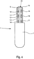
- Fig. 4
- ein weiteres Ausführungsbeispiel eines erfindungsgemäßen Schwimmkörpers in Seitenansicht und
- Fig. 5
- ein letztes Ausführungsbeispiel eines erfindungsgemäßen Schwimmkörpers in Seitenansicht.
- In
Fig. 1 ist ein typischer Anwendungsfall für einen aus dem Stand der Technik bekannten Schwimmkörper 1 dargestellt, mit dessen Hilfe der Füllstand eines in einem Behälter 2, 4 befindlichen Mediums 3 ermittelt werden soll. Dazu ist ein Referenzbehälter 4 derart mit dem Behälter 2 verbunden, dass der Füllstand des Mediums 3 im Behälter 2 dem Füllstand des Mediums 3 im Referenzbehälter 4 entspricht. Im Medium 3 im Referenzbehälter 4 schwimmt der dem Stand der Technik entsprechender Schwimmkörper 1, der teilweise aus dem Medium 3 herausragt. Der Schwimmkörper 4 wird durch die Wandung des Referenzbehälters 4 seitlich geführt, so dass er sich nur noch in Richtung der Längsachse des Referenzbehälters 4 bewegen kann. Jedoch ist zwischen dem Schwimmkörper 1 und der Wandung des Referenzbehälters 4 ein Spiel vorhanden, welches ein unvermeidbares und unvorhersagbares Verkippen des Schwimmkörpers 1 im Referenzbehälter 4 zur Folge hat. - Ein mit elektromagnetischen Wellen nach dem Radarprinzip arbeitendes Füllstandsmessgerät 5, 6 weist einen Sender 5 und einen Empfänger 6 für elektromagnetische Wellen auf und emittiert elektromagnetische Wellen, die sich im Wesentlichen entlang der Längsachse des Referenzbehälters 4 in Richtung auf den Schwimmkörper 1 ausbreiten. Der Referenzbehälter 4 stellt für die elektromagnetischen Wellen einen Hohlleiter dar. Der Teil des Schwimmkörpers 1, der aus dem Medium 3 ragt und ohne Berücksichtigung des Verkippens weitgehend senkrecht zur Längsachse des Referenzbehälters 4 erstreckt ist, ist ein Reflektor 20 für die vom Füllstandsmessgerät 5, 6 emittierten Wellen.
- Der erforderliche umlaufende Spalt zwischen dem Schwimmkörper 1 und der Wandung des Referenzbehälters 1 besitzt unerwünschte Eigenschaften, er begünstigt die Entstehung von Störreflexionen, die einer präzise Füllstandmessung abträglich sind. Zusätzlich entstehen durch das unvermeidbare und unvorhersagbare Verkippen des Schwimmkörpers 1 im Referenzbehälter 4 Unsymmetrien im erwähnten Spalt, welche die reflektierte elektromagnetische Welle ebenfalls abträglich beeinflussen. In den in den
Fig. 2 bis 5 schematisch dargestellten erfindungsgemäßen Ausführungsbeispielen des Schwimmkörpers 1 sind die Reflexionseigenschaften durch Feldtransformation gegenüber dem inFig. 1 dargestellten Stand der Technik signifikant verbessert. - Das in
Fig. 2a, 2b und3a dargestellte Ausführungsbeispiel des erfindungsgemäßen Schwimmkörpers 1 besteht aus einem zylinderförmigen Auftriebskörper 7, bei dem die bei einem idealen Zylinder vorhandenen Kanten jedoch abgestumpft sind. Der Auftriebskörper 7 ist bis auf den erforderlichen Spalt an den Innendurchmesser des Referenzbehälters 4 angepasst. An den aus dem Medium 3 ragenden Teil des Auftriebskörpers 7 schließt sich eine Feldschwächungsstruktur 8 an. Dabei ist der Auftriebskörper 7 ausgebildet wie ein aus dem Stand der Technik bekannter Schwimmkörper, der mit einem hier nicht gezeigten Magnetsystem ausgestattet ist. Deswegen kann der erfindungsgemäße Schwimmkörper 1 mit einem bestehenden Magnetsystemen ausgestattet werden, wodurch er kompatibel mit bestehenden Füllstandsmesssystemen ist, welche den Füllstand beispielsweise durch Magnetklappen oder einen Folgemagnet anzeigen. - Die Feldschwächungsstruktur 8 besteht aus zur Längsachse des Auftriebskörpers 7 konzentrischen Scheiben 9, 10, 11, 12 mit einer Abfolge aus Sicht des Füllstandmessgeräts 5 von einer Scheibe 9 mit großem Durchmesser, einer Scheibe 10 mit kleinem Durchmesser, einer Scheibe 11 mit großem Durchmesser und einer Scheibe 12 mit kleinem Durchmesser, also aus zwei Scheiben 10, 12 mit kleinem Durchmesser und zwei Scheiben 9, 11 mit großem Durchmesser. Der Durchmesser der großen Scheiben 9, 11 ist dabei deutlich größer als der der kleinen Scheiben 10, 12. Die Dicke einer jeden der Scheiben 9 - 12 beträgt im Wesentlichen ein Viertel der Wellenlänge der eingesetzten elektromagnetischen Wellen, bei anderen hier nicht dargestellten Ausführungsbeispielen beträgt die Dicke einer jeden der Scheiben im Wesentlichen ein ungeradzahlig Vielfaches eines Viertels der Wellenlänge der eingesetzten elektromagnetischen Wellen.
- Die Scheiben 9-12 bilden zusammen mit dem Teil der Oberfläche des Auftriebskörpers 7 einen λ/4-Filter, der weitgehend parallel zu den ebenen Flächen der Scheiben 9-12 ausgerichtet ist. In einer alternativen - hier jedoch nicht dargestellten - Ausführung ist die Dicke der Scheibe 12 wesentlich größer als ein Viertel der Wellenlänge, wodurch nur noch die Scheiben 9-11 einen λ/4-Filter bilden. Die ebene Fläche der großen Scheibe 9, welche dem Füllstandsmessgerät 5, 6 am nächsten liegt, bildet den Reflektor 20 für die vom Sender des Füllstandmessgeräts ausgesandten elektromagnetischen Wellen. In
Fig. 2b ist der Schwimmkörper 1 im Referenzbehälter 4 verkippt. Die Durchmesser der Scheiben 9-12 sind derart gewählt, dass keine der Scheiben 9-12 mit dem Referenzbehälter in Berührung kommen kann. Durch die Feldschwächungsstruktur 8 sind die Reflexionseigenschaften des erfindungsgemäßen Schwimmkörpers 1 sowohl im verkippten als auch nicht-verkippten Zustand besser als bei Schwimmkörpern nach dem Stand der Technik, vor allem aber sind die Reflexionseigenschaften des erfindungsgemäßen Schwimmkörpers 1 sowohl im verkippten als auch im nicht-verkippten Zustand praktisch gleichbleibend gut. Durch Auslegung der Feldschwächungsstruktur 8 als λ/4-Filter wird ein größerer Anteil der eingestrahlten Leistung wieder reflektiert, der Anteil der reflektierten elektromagnetischen Strahlung ist im Verhältnis zur insgesamt eingestrahlten Energie deutlich größer als im Fall der Auslegung der Feldschwächungsstruktur als reine Dämpfungsstruktur. Zwar wird auch im letzteren Fall das Signal/Rausch-Verhältnis verbessert, jedoch wird das eigentliche Nutzsignal nicht vergrößert. - In dem in
Fig. 3b dargestellten Ausführungsbeispiel wird ein Auftriebskörper 7 mit rundem Querschnitt durch die Wandung eines Referenzbehälters 1 mit recheckigem Querschnitt geführt, die Geometrien der Scheiben 9, 10 der Feldschwächungsstruktur 8 senkrecht zur Längsachse des Referenzbehälters 4 sind ebenfalls rechteckig. - In dem in
Fig. 4 dargestellten Ausführungsbeispiel ist die dem Füllstandsmessgerät 5, 6 näher liegende ebene Fläche des Auftriebskörpers 7 Teil der Feldschwächungsstruktur 8 und die Kante der Fläche nicht abgestumpft, wodurch die Dämpfungseigenschaften verändert werden. Die an dem Auftriebskörper 7 angefügte Feldschwächungsstruktur 8 besteht im Unterschied zu dem in denFig. 2a, 2b und3a gezeigten Ausführungsbeispiel aus drei Scheiben 10, 12, 14 mit kleinem Durchmesser und drei Scheiben 9, 11, 13 mit großem Durchmesser. Jede der kleinen Scheiben 10, 12, 14 ist jeweils mit einem Ring 15, 16, 17 aus einem anderen dielektrischen Material umgeben, deren Außendurchmesser im Wesentlichen dem Durchmesser der großen Scheiben 9, 11, 13 entspricht. Die Scheibe 9 mit einem großen Durchmesser, die dem Füllstandsmessgerät 5,6 am nächsten liegt, ist gewölbt und die gesamte angefügte Feldschwächungsstruktur 8 ist mit einem dielektrischen Material 18 umhüllt. - In dem in
Fig. 5 dargestellten abschließenden Ausführungsbeispiel besteht der Schwimmkörper 1 aus einer Feldschwächungsstruktur 8, die gleichzeitig auch die Funktionalität der Auftriebskörpers 7 übernimmt. Die Feldschwächungsstruktur 8 ist seitlich mit einem dielektrischen Material 18 umhüllt.
Claims (7)
- Schwimmkörper (1) zur Anzeige des Füllstandes eines Mediums (3) in einem Behälter (2), wobei der Schwimmkörper (1) bei bestimmungsgemäßem Einsatz von der Wandung des Behälters (2, 4) geführt wird und dazu geeignet ist, von einem Sender (5) emittierte elektromagnetische Wellen in Richtung auf einen Empfänger (6) zu reflektieren, wobei bei bestimmungsgemäßem Einsatz zumindest die dem Sender (5) zugewandte Seite des Schwimmkörpers (1) als Reflektor (20) zur Reflexion der elektromagnetischen Wellen auf den Empfänger (6) ausgebildet ist,
dadurch gekennzeichnet,
dass bei bestimmungsgemäßern Einsatz aus Sicht des Senders (5) hinter dem Reflektor (20) eine Feldschwächungsstruktur (8) so ausgebildet ist, dass die mit der Feldschwächungsstruktur (8) wechselwirkende elektromagnetische Welle geschwächt wird, dass die Feldschwächungsstruktur (8) als λ/4-Filter realisiert ist und dass die Feldschwächungsstruktur (8) aus abwechselnd hintereinander angeordneten großen Scheiben (9, 11, 13, 19) und kleinen Scheiben (10, 12, 14) besteht. - Schwimmkörper (1) nach Anspruch 1, dadurch gekennzeichnet, dass die obere Fläche des Reflektors (20) eben oder gewölbt ist.
- Schwimmkörper (1) nach Anspruch 1 oder 2, dadurch gekennzeichnet, dass die Scheiben (9,10, 11, 12, 13, 14, 19) eine Dicke von im Wesentlichen einem ungeradzahligen Vielfachen eines Viertels der Wellenlänge der von dem Sender (5) emittierten elektromagnetischen Strahlung aufweisen.
- Schwimmkörper (1) nach einem der Ansprüche 1 bis 3, dadurch gekennzeichnet, dass der Schwimmkörper (1) einen Auftriebskörper (7) und die daran anschließende Feldschwächungsstruktur (8) aufweist und der Auftriebskörper (7) und die Feldschwächungsstruktur (8) in ihren Abmessungen so gewählt sind, dass bei einem Verkippen des Schwimmkörpers (1) im Behälter (2, 4) der Auftriebskörper (7) die Wandung des Behälters (2, 4) kontaktiert, die Feldschwächungsstruktur (8) die Wandung des Behälters (2, 4) aber nicht kontaktiert.
- Schwimmkörper (1) nach Anspruch 4, dadurch gekennzeichnet, dass der Reflektor (20) und die Feldschwächungsstruktur (8) auch die Funktionalität des Auftriebskörpers (7) übernehmen und die Feldschwächungsstruktur (8) zumindest an den Kontaktstellen mit der Wandung des Behälters (2, 4) mit einem dielektrischen Material umhüllt ist.
- Schwimmkörper (1) nach einem der Ansprüche 1 bis 5, dadurch gekennzeichnet, dass mindestens eine der kleinen Scheiben (10, 12, 14) von mindestens einem Ring (15, 16, 17) aus mindestens einem dielektrischen Material umgeben ist.
- Schwimmkörper (1) nach einem der Ansprüche 1 bis 6, dadurch gekennzeichnet, dass der Reflektor (20) und die Feldschwächungsstruktur (8) mit einem dielektrischen Material (18) umhüllt sind.
Applications Claiming Priority (1)
| Application Number | Priority Date | Filing Date | Title |
|---|---|---|---|
| DE201110106568 DE102011106568B4 (de) | 2011-06-28 | 2011-06-28 | Schwimmkörper zur Anzeige eines Füllstandes |
Publications (2)
| Publication Number | Publication Date |
|---|---|
| EP2565595A1 EP2565595A1 (de) | 2013-03-06 |
| EP2565595B1 true EP2565595B1 (de) | 2017-05-17 |
Family
ID=45936638
Family Applications (1)
| Application Number | Title | Priority Date | Filing Date |
|---|---|---|---|
| EP12001961.7A Not-in-force EP2565595B1 (de) | 2011-06-28 | 2012-03-20 | Schwimmkörper zur Anzeige eines Füllstandes |
Country Status (5)
| Country | Link |
|---|---|
| US (1) | US8881589B2 (de) |
| EP (1) | EP2565595B1 (de) |
| CN (1) | CN102853881B (de) |
| CA (1) | CA2772834C (de) |
| DE (1) | DE102011106568B4 (de) |
Families Citing this family (7)
| Publication number | Priority date | Publication date | Assignee | Title |
|---|---|---|---|---|
| DE102013221213A1 (de) | 2013-10-18 | 2014-11-06 | Ifm Electronic Gmbh | Schwimmkörper und Anordnung zum Messen eines Füllstands |
| DE102013221223A1 (de) | 2013-10-18 | 2014-12-04 | Ifm Electronic Gmbh | Schwimmkörper und Anordnung zum Messen eines Füllstands |
| CN104391515B (zh) * | 2014-12-02 | 2017-09-29 | 佛山市南海北沙制药有限公司 | 一种制造药品用的甲醇储存罐供给和输出控制装置 |
| EP3760984B1 (de) * | 2019-07-03 | 2023-08-30 | Rosemount Tank Radar AB | Übertragungsleitungssonde |
| US11391616B2 (en) * | 2020-08-21 | 2022-07-19 | Ametek Magnetrol Usa, Llc | Redundant level measuring system |
| CN114636459B (zh) * | 2022-04-07 | 2022-12-13 | 江苏美安特科技有限公司 | 一种新型磁翻板液位计 |
| CN118168630B (zh) * | 2024-05-14 | 2024-07-19 | 山东信泰智能科技有限公司 | 一种液位测量计及其测量方法 |
Family Cites Families (15)
| Publication number | Priority date | Publication date | Assignee | Title |
|---|---|---|---|---|
| US4585317A (en) * | 1981-11-05 | 1986-04-29 | Marvin Hodges | Reflector with attenuating connecting plates |
| SE441306B (sv) * | 1984-04-25 | 1985-09-23 | Saab Marine Electronics | Sett och anordning for metning av nivan hos ett i en behallare forvarat flytande material |
| JPS6239801A (ja) * | 1985-08-14 | 1987-02-20 | Minolta Camera Co Ltd | 半透鏡 |
| JP2560712B2 (ja) * | 1987-02-20 | 1996-12-04 | 富士ゼロックス株式会社 | 光ビ−ム走査装置 |
| JPH0254031A (ja) | 1988-08-17 | 1990-02-23 | Toto Ltd | 検尿便器 |
| US5474198A (en) * | 1992-07-29 | 1995-12-12 | Saab-Scania Ab | Stillpipe sealing device |
| JPH08154008A (ja) * | 1994-11-28 | 1996-06-11 | Nec Eng Ltd | 導波管同軸変換器 |
| US5614831A (en) * | 1995-02-13 | 1997-03-25 | Saab Marine Electronics Ab | Method and apparatus for level gauging using radar in floating roof tanks |
| EP1004858A1 (de) * | 1998-11-27 | 2000-05-31 | Endress + Hauser GmbH + Co. | Füllstandsmessgerät |
| JP2004150952A (ja) * | 2002-10-30 | 2004-05-27 | Osaka Gas Co Ltd | 液面計及びその交換方法 |
| US6795015B2 (en) * | 2003-01-29 | 2004-09-21 | Saab Rosemount Tank Radar Ab | Bottom reflector for a radar-based level gauge |
| US20050241391A1 (en) * | 2004-04-29 | 2005-11-03 | K-Tek, L.L.C. | Targeted guided wire level measuring device |
| JP4058062B2 (ja) * | 2005-06-21 | 2008-03-05 | 昭和機器工業株式会社 | フロート式の磁歪式液面検知装置 |
| EP2101907B1 (de) * | 2007-01-11 | 2014-11-12 | The Petroleum Oil and Gas Corporation of South Africa (Pty) Ltd. | Verfahren zum schutz der internen filter eines ltft-schlammblasen-reaktors |
| DE102007005619A1 (de) * | 2007-01-31 | 2008-08-07 | Krohne S.A. | Füllstandsmeßvorrichtung |
-
2011
- 2011-06-28 DE DE201110106568 patent/DE102011106568B4/de not_active Expired - Fee Related
-
2012
- 2012-03-20 EP EP12001961.7A patent/EP2565595B1/de not_active Not-in-force
- 2012-03-29 CA CA2772834A patent/CA2772834C/en active Active
- 2012-04-10 US US13/443,033 patent/US8881589B2/en active Active
- 2012-06-28 CN CN201210217902.1A patent/CN102853881B/zh not_active Expired - Fee Related
Also Published As
| Publication number | Publication date |
|---|---|
| CA2772834C (en) | 2015-11-24 |
| CN102853881A (zh) | 2013-01-02 |
| DE102011106568B4 (de) | 2013-09-19 |
| US8881589B2 (en) | 2014-11-11 |
| CA2772834A1 (en) | 2012-12-28 |
| CN102853881B (zh) | 2017-12-29 |
| US20130000401A1 (en) | 2013-01-03 |
| DE102011106568A1 (de) | 2013-01-03 |
| EP2565595A1 (de) | 2013-03-06 |
Similar Documents
| Publication | Publication Date | Title |
|---|---|---|
| DE102011106568B4 (de) | Schwimmkörper zur Anzeige eines Füllstandes | |
| EP1311807B1 (de) | Vorrichtung zur bestimmung des füllstandes eines füllguts in einem behälter | |
| EP0505402B1 (de) | Ultraschall-durchflussmesser | |
| EP3049772B1 (de) | Flüssigkeitstank mit einem ultraschallsensor | |
| EP3158325B1 (de) | Mikrowellenmessvorrichtung, anordnung und verfahren zur überprüfung von stabförmigen artikeln oder eines materialstrangs der tabak verarbeitenden industrie sowie maschine der tabak verarbeitenden industrie | |
| EP2631993A1 (de) | Dielektrische Antenne und nach dem Radar-Prinzip arbeitendes Füllstandmessgerät | |
| EP2116820B1 (de) | Verwendung einer Anpassvorrichtung, Messgerät mit Anpassvorrichtung und Verfahren zum Betreiben eines Wellenleiters | |
| EP2687830B1 (de) | Verfahren zur Zustandsüberwachung eines nach dem Radar-Prinzip arbeitenden Füllstandmessgeräts und entsprechendes Füllstandmessgerät | |
| DE19922606A1 (de) | Anordnung aus einem Hohlleiter und einer Antenne | |
| DE4311963A1 (de) | Füllstandsmeßgerät | |
| DE3536365C2 (de) | ||
| EP0942264A2 (de) | Anordnung zur Füllstandsmessung | |
| EP2634858B1 (de) | Mikrowellenfenster und nach dem Radar-Prinzip arbeitendes Füllstandmesssystem | |
| DE10164107C1 (de) | Mikrowellen-Messeinrichtung zur Bestimmung der Beladung einer Zweiphasenströmung | |
| DE102009026433A1 (de) | Anordnung zur Füllstandsmessung mit einem mit Mikrowellen arbeitenden Füllstandsmessgerät | |
| DE69008955T2 (de) | Detektor zur Anzeige einer Flüssigkeit unter Verwendung eines zusammengesetzten Wellenleiters sowie einer elastischen Welle. | |
| DE1623569A1 (de) | Akustisches Bohrloch-Untersuchungsgeraet | |
| DE102014109399A1 (de) | Sensor für eine Rollenbahn und Verfahren zum Erkennen von auf einer Rollenbahn befindlichen Objekten | |
| EP1098295A2 (de) | Ultraschallwellenleiter | |
| EP1801549A2 (de) | Hohlleiter für ein Mikrowellen-Füllstandsmessgerät | |
| EP3084369B1 (de) | Radarfüllstandmessgerät | |
| DE102005011778A1 (de) | Verfahren zur Messung des Füllstands eines in einem Behälter vorgesehenen Mediums auf der Grundlage des Radar-Prinzips | |
| EP3159662B1 (de) | Seilsonde, füllstandmessgerät und verfahren zum herstellen einer seilsonde | |
| DE2519986C3 (de) | MeBhilfseinrichtung für Radargeräte mit Empfangs- und Rücksendeantenne zum Simulieren entfernter Zielobjekte | |
| DE102017009569B4 (de) | Messeinrichtung und Verfahren zur Ermittlung einer Fluidgröße |
Legal Events
| Date | Code | Title | Description |
|---|---|---|---|
| PUAI | Public reference made under article 153(3) epc to a published international application that has entered the european phase |
Free format text: ORIGINAL CODE: 0009012 |
|
| AK | Designated contracting states |
Kind code of ref document: A1 Designated state(s): AL AT BE BG CH CY CZ DE DK EE ES FI FR GB GR HR HU IE IS IT LI LT LU LV MC MK MT NL NO PL PT RO RS SE SI SK SM TR |
|
| AX | Request for extension of the european patent |
Extension state: BA ME |
|
| 17P | Request for examination filed |
Effective date: 20130906 |
|
| RBV | Designated contracting states (corrected) |
Designated state(s): AL AT BE BG CH CY CZ DE DK EE ES FI FR GB GR HR HU IE IS IT LI LT LU LV MC MK MT NL NO PL PT RO RS SE SI SK SM TR |
|
| GRAP | Despatch of communication of intention to grant a patent |
Free format text: ORIGINAL CODE: EPIDOSNIGR1 |
|
| INTG | Intention to grant announced |
Effective date: 20161128 |
|
| GRAS | Grant fee paid |
Free format text: ORIGINAL CODE: EPIDOSNIGR3 |
|
| GRAA | (expected) grant |
Free format text: ORIGINAL CODE: 0009210 |
|
| AK | Designated contracting states |
Kind code of ref document: B1 Designated state(s): AL AT BE BG CH CY CZ DE DK EE ES FI FR GB GR HR HU IE IS IT LI LT LU LV MC MK MT NL NO PL PT RO RS SE SI SK SM TR |
|
| REG | Reference to a national code |
Ref country code: GB Ref legal event code: FG4D Free format text: NOT ENGLISH |
|
| REG | Reference to a national code |
Ref country code: CH Ref legal event code: EP |
|
| REG | Reference to a national code |
Ref country code: IE Ref legal event code: FG4D Free format text: LANGUAGE OF EP DOCUMENT: GERMAN |
|
| REG | Reference to a national code |
Ref country code: AT Ref legal event code: REF Ref document number: 894885 Country of ref document: AT Kind code of ref document: T Effective date: 20170615 |
|
| REG | Reference to a national code |
Ref country code: DE Ref legal event code: R096 Ref document number: 502012010351 Country of ref document: DE |
|
| REG | Reference to a national code |
Ref country code: NL Ref legal event code: MP Effective date: 20170517 |
|
| REG | Reference to a national code |
Ref country code: LT Ref legal event code: MG4D |
|
| PG25 | Lapsed in a contracting state [announced via postgrant information from national office to epo] |
Ref country code: GR Free format text: LAPSE BECAUSE OF FAILURE TO SUBMIT A TRANSLATION OF THE DESCRIPTION OR TO PAY THE FEE WITHIN THE PRESCRIBED TIME-LIMIT Effective date: 20170818 Ref country code: ES Free format text: LAPSE BECAUSE OF FAILURE TO SUBMIT A TRANSLATION OF THE DESCRIPTION OR TO PAY THE FEE WITHIN THE PRESCRIBED TIME-LIMIT Effective date: 20170517 Ref country code: NO Free format text: LAPSE BECAUSE OF FAILURE TO SUBMIT A TRANSLATION OF THE DESCRIPTION OR TO PAY THE FEE WITHIN THE PRESCRIBED TIME-LIMIT Effective date: 20170817 Ref country code: HR Free format text: LAPSE BECAUSE OF FAILURE TO SUBMIT A TRANSLATION OF THE DESCRIPTION OR TO PAY THE FEE WITHIN THE PRESCRIBED TIME-LIMIT Effective date: 20170517 Ref country code: LT Free format text: LAPSE BECAUSE OF FAILURE TO SUBMIT A TRANSLATION OF THE DESCRIPTION OR TO PAY THE FEE WITHIN THE PRESCRIBED TIME-LIMIT Effective date: 20170517 Ref country code: FI Free format text: LAPSE BECAUSE OF FAILURE TO SUBMIT A TRANSLATION OF THE DESCRIPTION OR TO PAY THE FEE WITHIN THE PRESCRIBED TIME-LIMIT Effective date: 20170517 |
|
| PG25 | Lapsed in a contracting state [announced via postgrant information from national office to epo] |
Ref country code: LV Free format text: LAPSE BECAUSE OF FAILURE TO SUBMIT A TRANSLATION OF THE DESCRIPTION OR TO PAY THE FEE WITHIN THE PRESCRIBED TIME-LIMIT Effective date: 20170517 Ref country code: BG Free format text: LAPSE BECAUSE OF FAILURE TO SUBMIT A TRANSLATION OF THE DESCRIPTION OR TO PAY THE FEE WITHIN THE PRESCRIBED TIME-LIMIT Effective date: 20170817 Ref country code: PL Free format text: LAPSE BECAUSE OF FAILURE TO SUBMIT A TRANSLATION OF THE DESCRIPTION OR TO PAY THE FEE WITHIN THE PRESCRIBED TIME-LIMIT Effective date: 20170517 Ref country code: SE Free format text: LAPSE BECAUSE OF FAILURE TO SUBMIT A TRANSLATION OF THE DESCRIPTION OR TO PAY THE FEE WITHIN THE PRESCRIBED TIME-LIMIT Effective date: 20170517 Ref country code: RS Free format text: LAPSE BECAUSE OF FAILURE TO SUBMIT A TRANSLATION OF THE DESCRIPTION OR TO PAY THE FEE WITHIN THE PRESCRIBED TIME-LIMIT Effective date: 20170517 Ref country code: NL Free format text: LAPSE BECAUSE OF FAILURE TO SUBMIT A TRANSLATION OF THE DESCRIPTION OR TO PAY THE FEE WITHIN THE PRESCRIBED TIME-LIMIT Effective date: 20170517 Ref country code: IS Free format text: LAPSE BECAUSE OF FAILURE TO SUBMIT A TRANSLATION OF THE DESCRIPTION OR TO PAY THE FEE WITHIN THE PRESCRIBED TIME-LIMIT Effective date: 20170917 |
|
| PG25 | Lapsed in a contracting state [announced via postgrant information from national office to epo] |
Ref country code: SK Free format text: LAPSE BECAUSE OF FAILURE TO SUBMIT A TRANSLATION OF THE DESCRIPTION OR TO PAY THE FEE WITHIN THE PRESCRIBED TIME-LIMIT Effective date: 20170517 Ref country code: RO Free format text: LAPSE BECAUSE OF FAILURE TO SUBMIT A TRANSLATION OF THE DESCRIPTION OR TO PAY THE FEE WITHIN THE PRESCRIBED TIME-LIMIT Effective date: 20170517 Ref country code: DK Free format text: LAPSE BECAUSE OF FAILURE TO SUBMIT A TRANSLATION OF THE DESCRIPTION OR TO PAY THE FEE WITHIN THE PRESCRIBED TIME-LIMIT Effective date: 20170517 Ref country code: EE Free format text: LAPSE BECAUSE OF FAILURE TO SUBMIT A TRANSLATION OF THE DESCRIPTION OR TO PAY THE FEE WITHIN THE PRESCRIBED TIME-LIMIT Effective date: 20170517 Ref country code: CZ Free format text: LAPSE BECAUSE OF FAILURE TO SUBMIT A TRANSLATION OF THE DESCRIPTION OR TO PAY THE FEE WITHIN THE PRESCRIBED TIME-LIMIT Effective date: 20170517 |
|
| REG | Reference to a national code |
Ref country code: DE Ref legal event code: R097 Ref document number: 502012010351 Country of ref document: DE |
|
| PG25 | Lapsed in a contracting state [announced via postgrant information from national office to epo] |
Ref country code: IT Free format text: LAPSE BECAUSE OF FAILURE TO SUBMIT A TRANSLATION OF THE DESCRIPTION OR TO PAY THE FEE WITHIN THE PRESCRIBED TIME-LIMIT Effective date: 20170517 Ref country code: SM Free format text: LAPSE BECAUSE OF FAILURE TO SUBMIT A TRANSLATION OF THE DESCRIPTION OR TO PAY THE FEE WITHIN THE PRESCRIBED TIME-LIMIT Effective date: 20170517 |
|
| PLBE | No opposition filed within time limit |
Free format text: ORIGINAL CODE: 0009261 |
|
| STAA | Information on the status of an ep patent application or granted ep patent |
Free format text: STATUS: NO OPPOSITION FILED WITHIN TIME LIMIT |
|
| REG | Reference to a national code |
Ref country code: FR Ref legal event code: PLFP Year of fee payment: 7 |
|
| 26N | No opposition filed |
Effective date: 20180220 |
|
| PG25 | Lapsed in a contracting state [announced via postgrant information from national office to epo] |
Ref country code: SI Free format text: LAPSE BECAUSE OF FAILURE TO SUBMIT A TRANSLATION OF THE DESCRIPTION OR TO PAY THE FEE WITHIN THE PRESCRIBED TIME-LIMIT Effective date: 20170517 |
|
| PG25 | Lapsed in a contracting state [announced via postgrant information from national office to epo] |
Ref country code: MT Free format text: LAPSE BECAUSE OF FAILURE TO SUBMIT A TRANSLATION OF THE DESCRIPTION OR TO PAY THE FEE WITHIN THE PRESCRIBED TIME-LIMIT Effective date: 20170517 |
|
| GBPC | Gb: european patent ceased through non-payment of renewal fee |
Effective date: 20180320 |
|
| PG25 | Lapsed in a contracting state [announced via postgrant information from national office to epo] |
Ref country code: MC Free format text: LAPSE BECAUSE OF FAILURE TO SUBMIT A TRANSLATION OF THE DESCRIPTION OR TO PAY THE FEE WITHIN THE PRESCRIBED TIME-LIMIT Effective date: 20170517 |
|
| REG | Reference to a national code |
Ref country code: BE Ref legal event code: MM Effective date: 20180331 |
|
| REG | Reference to a national code |
Ref country code: IE Ref legal event code: MM4A |
|
| PG25 | Lapsed in a contracting state [announced via postgrant information from national office to epo] |
Ref country code: LU Free format text: LAPSE BECAUSE OF NON-PAYMENT OF DUE FEES Effective date: 20180320 |
|
| PG25 | Lapsed in a contracting state [announced via postgrant information from national office to epo] |
Ref country code: IE Free format text: LAPSE BECAUSE OF NON-PAYMENT OF DUE FEES Effective date: 20180320 |
|
| PG25 | Lapsed in a contracting state [announced via postgrant information from national office to epo] |
Ref country code: GB Free format text: LAPSE BECAUSE OF NON-PAYMENT OF DUE FEES Effective date: 20180320 Ref country code: BE Free format text: LAPSE BECAUSE OF NON-PAYMENT OF DUE FEES Effective date: 20180331 |
|
| REG | Reference to a national code |
Ref country code: AT Ref legal event code: MM01 Ref document number: 894885 Country of ref document: AT Kind code of ref document: T Effective date: 20180320 |
|
| PG25 | Lapsed in a contracting state [announced via postgrant information from national office to epo] |
Ref country code: AT Free format text: LAPSE BECAUSE OF NON-PAYMENT OF DUE FEES Effective date: 20180320 |
|
| PG25 | Lapsed in a contracting state [announced via postgrant information from national office to epo] |
Ref country code: TR Free format text: LAPSE BECAUSE OF FAILURE TO SUBMIT A TRANSLATION OF THE DESCRIPTION OR TO PAY THE FEE WITHIN THE PRESCRIBED TIME-LIMIT Effective date: 20170517 |
|
| PG25 | Lapsed in a contracting state [announced via postgrant information from national office to epo] |
Ref country code: HU Free format text: LAPSE BECAUSE OF FAILURE TO SUBMIT A TRANSLATION OF THE DESCRIPTION OR TO PAY THE FEE WITHIN THE PRESCRIBED TIME-LIMIT; INVALID AB INITIO Effective date: 20120320 Ref country code: PT Free format text: LAPSE BECAUSE OF FAILURE TO SUBMIT A TRANSLATION OF THE DESCRIPTION OR TO PAY THE FEE WITHIN THE PRESCRIBED TIME-LIMIT Effective date: 20170517 |
|
| PG25 | Lapsed in a contracting state [announced via postgrant information from national office to epo] |
Ref country code: CY Free format text: LAPSE BECAUSE OF FAILURE TO SUBMIT A TRANSLATION OF THE DESCRIPTION OR TO PAY THE FEE WITHIN THE PRESCRIBED TIME-LIMIT Effective date: 20170517 Ref country code: MK Free format text: LAPSE BECAUSE OF NON-PAYMENT OF DUE FEES Effective date: 20170517 |
|
| PG25 | Lapsed in a contracting state [announced via postgrant information from national office to epo] |
Ref country code: AL Free format text: LAPSE BECAUSE OF FAILURE TO SUBMIT A TRANSLATION OF THE DESCRIPTION OR TO PAY THE FEE WITHIN THE PRESCRIBED TIME-LIMIT Effective date: 20170517 |
|
| PGFP | Annual fee paid to national office [announced via postgrant information from national office to epo] |
Ref country code: CH Payment date: 20220321 Year of fee payment: 11 |
|
| PGFP | Annual fee paid to national office [announced via postgrant information from national office to epo] |
Ref country code: FR Payment date: 20220322 Year of fee payment: 11 |
|
| PGFP | Annual fee paid to national office [announced via postgrant information from national office to epo] |
Ref country code: DE Payment date: 20220520 Year of fee payment: 11 |
|
| REG | Reference to a national code |
Ref country code: DE Ref legal event code: R119 Ref document number: 502012010351 Country of ref document: DE |
|
| REG | Reference to a national code |
Ref country code: CH Ref legal event code: PL |
|
| PG25 | Lapsed in a contracting state [announced via postgrant information from national office to epo] |
Ref country code: LI Free format text: LAPSE BECAUSE OF NON-PAYMENT OF DUE FEES Effective date: 20230331 Ref country code: FR Free format text: LAPSE BECAUSE OF NON-PAYMENT OF DUE FEES Effective date: 20230331 Ref country code: DE Free format text: LAPSE BECAUSE OF NON-PAYMENT OF DUE FEES Effective date: 20231003 Ref country code: CH Free format text: LAPSE BECAUSE OF NON-PAYMENT OF DUE FEES Effective date: 20230331 |