EP2565150A1 - Support arm - Google Patents
Support arm Download PDFInfo
- Publication number
- EP2565150A1 EP2565150A1 EP10838393A EP10838393A EP2565150A1 EP 2565150 A1 EP2565150 A1 EP 2565150A1 EP 10838393 A EP10838393 A EP 10838393A EP 10838393 A EP10838393 A EP 10838393A EP 2565150 A1 EP2565150 A1 EP 2565150A1
- Authority
- EP
- European Patent Office
- Prior art keywords
- arm
- tip end
- shape
- gravity center
- base
- Prior art date
- Legal status (The legal status is an assumption and is not a legal conclusion. Google has not performed a legal analysis and makes no representation as to the accuracy of the status listed.)
- Withdrawn
Links
- 230000007246 mechanism Effects 0.000 claims abstract description 87
- 230000005484 gravity Effects 0.000 claims description 83
- 230000004308 accommodation Effects 0.000 claims description 7
- 239000007788 liquid Substances 0.000 claims description 7
- 238000010586 diagram Methods 0.000 description 16
- 239000000446 fuel Substances 0.000 description 10
- 238000002485 combustion reaction Methods 0.000 description 6
- 238000006073 displacement reaction Methods 0.000 description 6
- 230000000694 effects Effects 0.000 description 6
- 239000002828 fuel tank Substances 0.000 description 5
- 230000007704 transition Effects 0.000 description 5
- 238000010276 construction Methods 0.000 description 3
- LFQSCWFLJHTTHZ-UHFFFAOYSA-N Ethanol Chemical compound CCO LFQSCWFLJHTTHZ-UHFFFAOYSA-N 0.000 description 2
- ATUOYWHBWRKTHZ-UHFFFAOYSA-N Propane Chemical compound CCC ATUOYWHBWRKTHZ-UHFFFAOYSA-N 0.000 description 2
- 238000009434 installation Methods 0.000 description 2
- 239000003990 capacitor Substances 0.000 description 1
- 239000003502 gasoline Substances 0.000 description 1
- 238000003780 insertion Methods 0.000 description 1
- 230000037431 insertion Effects 0.000 description 1
- 238000012986 modification Methods 0.000 description 1
- 230000004048 modification Effects 0.000 description 1
- 239000001294 propane Substances 0.000 description 1
Images


Classifications
-
- B—PERFORMING OPERATIONS; TRANSPORTING
- B25—HAND TOOLS; PORTABLE POWER-DRIVEN TOOLS; MANIPULATORS
- B25J—MANIPULATORS; CHAMBERS PROVIDED WITH MANIPULATION DEVICES
- B25J9/00—Programme-controlled manipulators
- B25J9/10—Programme-controlled manipulators characterised by positioning means for manipulator elements
- B25J9/106—Programme-controlled manipulators characterised by positioning means for manipulator elements with articulated links
- B25J9/1065—Programme-controlled manipulators characterised by positioning means for manipulator elements with articulated links with parallelograms
-
- B—PERFORMING OPERATIONS; TRANSPORTING
- B60—VEHICLES IN GENERAL
- B60L—PROPULSION OF ELECTRICALLY-PROPELLED VEHICLES; SUPPLYING ELECTRIC POWER FOR AUXILIARY EQUIPMENT OF ELECTRICALLY-PROPELLED VEHICLES; ELECTRODYNAMIC BRAKE SYSTEMS FOR VEHICLES IN GENERAL; MAGNETIC SUSPENSION OR LEVITATION FOR VEHICLES; MONITORING OPERATING VARIABLES OF ELECTRICALLY-PROPELLED VEHICLES; ELECTRIC SAFETY DEVICES FOR ELECTRICALLY-PROPELLED VEHICLES
- B60L53/00—Methods of charging batteries, specially adapted for electric vehicles; Charging stations or on-board charging equipment therefor; Exchange of energy storage elements in electric vehicles
- B60L53/10—Methods of charging batteries, specially adapted for electric vehicles; Charging stations or on-board charging equipment therefor; Exchange of energy storage elements in electric vehicles characterised by the energy transfer between the charging station and the vehicle
- B60L53/14—Conductive energy transfer
- B60L53/16—Connectors, e.g. plugs or sockets, specially adapted for charging electric vehicles
-
- H—ELECTRICITY
- H02—GENERATION; CONVERSION OR DISTRIBUTION OF ELECTRIC POWER
- H02G—INSTALLATION OF ELECTRIC CABLES OR LINES, OR OF COMBINED OPTICAL AND ELECTRIC CABLES OR LINES
- H02G15/00—Cable fittings
- H02G15/007—Devices for relieving mechanical stress
-
- Y—GENERAL TAGGING OF NEW TECHNOLOGICAL DEVELOPMENTS; GENERAL TAGGING OF CROSS-SECTIONAL TECHNOLOGIES SPANNING OVER SEVERAL SECTIONS OF THE IPC; TECHNICAL SUBJECTS COVERED BY FORMER USPC CROSS-REFERENCE ART COLLECTIONS [XRACs] AND DIGESTS
- Y02—TECHNOLOGIES OR APPLICATIONS FOR MITIGATION OR ADAPTATION AGAINST CLIMATE CHANGE
- Y02T—CLIMATE CHANGE MITIGATION TECHNOLOGIES RELATED TO TRANSPORTATION
- Y02T10/00—Road transport of goods or passengers
- Y02T10/60—Other road transportation technologies with climate change mitigation effect
- Y02T10/70—Energy storage systems for electromobility, e.g. batteries
-
- Y—GENERAL TAGGING OF NEW TECHNOLOGICAL DEVELOPMENTS; GENERAL TAGGING OF CROSS-SECTIONAL TECHNOLOGIES SPANNING OVER SEVERAL SECTIONS OF THE IPC; TECHNICAL SUBJECTS COVERED BY FORMER USPC CROSS-REFERENCE ART COLLECTIONS [XRACs] AND DIGESTS
- Y02—TECHNOLOGIES OR APPLICATIONS FOR MITIGATION OR ADAPTATION AGAINST CLIMATE CHANGE
- Y02T—CLIMATE CHANGE MITIGATION TECHNOLOGIES RELATED TO TRANSPORTATION
- Y02T10/00—Road transport of goods or passengers
- Y02T10/60—Other road transportation technologies with climate change mitigation effect
- Y02T10/7072—Electromobility specific charging systems or methods for batteries, ultracapacitors, supercapacitors or double-layer capacitors
-
- Y—GENERAL TAGGING OF NEW TECHNOLOGICAL DEVELOPMENTS; GENERAL TAGGING OF CROSS-SECTIONAL TECHNOLOGIES SPANNING OVER SEVERAL SECTIONS OF THE IPC; TECHNICAL SUBJECTS COVERED BY FORMER USPC CROSS-REFERENCE ART COLLECTIONS [XRACs] AND DIGESTS
- Y02—TECHNOLOGIES OR APPLICATIONS FOR MITIGATION OR ADAPTATION AGAINST CLIMATE CHANGE
- Y02T—CLIMATE CHANGE MITIGATION TECHNOLOGIES RELATED TO TRANSPORTATION
- Y02T90/00—Enabling technologies or technologies with a potential or indirect contribution to GHG emissions mitigation
- Y02T90/10—Technologies relating to charging of electric vehicles
- Y02T90/12—Electric charging stations
-
- Y—GENERAL TAGGING OF NEW TECHNOLOGICAL DEVELOPMENTS; GENERAL TAGGING OF CROSS-SECTIONAL TECHNOLOGIES SPANNING OVER SEVERAL SECTIONS OF THE IPC; TECHNICAL SUBJECTS COVERED BY FORMER USPC CROSS-REFERENCE ART COLLECTIONS [XRACs] AND DIGESTS
- Y02—TECHNOLOGIES OR APPLICATIONS FOR MITIGATION OR ADAPTATION AGAINST CLIMATE CHANGE
- Y02T—CLIMATE CHANGE MITIGATION TECHNOLOGIES RELATED TO TRANSPORTATION
- Y02T90/00—Enabling technologies or technologies with a potential or indirect contribution to GHG emissions mitigation
- Y02T90/10—Technologies relating to charging of electric vehicles
- Y02T90/14—Plug-in electric vehicles
Definitions
- the present invention relates to a support arm, and particularly to a support arm supporting a charge connector for a hybrid vehicle or the like.
- Patent Literature 1 shows as a conventional mechanism, an apparatus ( Fig. 6 ) in which a parallelogram linkage mechanism is formed by two, upper and lower arms and shows as an embodiment of the invention, an example in which a single arm is provided ( Fig. 1 and the like).
- Patent Literature 2 shows an arm mechanism having two, upper and lower arms.
- Patent Literature 1 shows a support arm with a gravity compensation function formed of a single arm, this apparatus is completely different in premise and specific construction from the invention of the subject application premised on a plurality of arms.
- the present invention was made in view of the problems as described above, and an object of the present invention is to provide a support arm great in a movable range of an arm.
- a support arm includes a base, an intermediate member, a tip end member, a first parallelogram linkage mechanism provided between the base and the intermediate member and including a first arm and a second arm, and a second parallelogram linkage mechanism provided between the intermediate member and the tip end member and including a third arm and a fourth arm.
- the first arm, the second arm, the third arm, and the fourth arm are each formed in an L shape.
- the first arm has a first base portion constructed by a short-side portion of the L shape and pivotably connected to the base and a first tip end portion constructed by a long-side portion of the L shape and pivotably connected to the intermediate member.
- the second arm has a second base portion constructed by a short-side portion of the L shape and pivotably connected to the intermediate member and a second tip end portion constructed by a long-side portion of the L shape and pivotably connected to the base.
- the first tip end portion and the second tip end portion are provided to be opposed to the second base portion and the first base portion, respectively.
- the third arm has a third base portion constructed by a short-side portion of the L shape and pivotably connected to the intermediate member and a third tip end portion constructed by a long-side portion of the L shape and pivotably connected to the tip end member.
- the fourth arm has a fourth base portion constructed by a short-side portion of the L shape and pivotably connected to the tip end member and a fourth tip end portion constructed by a long-side portion of the L shape and pivotably connected to the intermediate member.
- the third tip end portion and the fourth tip end portion are provided to be opposed to the fourth base portion and the third base portion, respectively.
- the first parallelogram linkage mechanism includes a pulley fixed to the first arm or the second arm and an elastic member fixed to the base and the intermediate member.
- the elastic member is provided to reach a second end portion provided on the intermediate member from a first end portion provided on the base around the pulley.
- the first arm has an elongated hole formed in the long-side portion of the L shape along a direction in which the long-side portion extends and an adjustment mechanism capable of fixing the pulley to the elongated hole and adjusting a position of the pulley along the elongated hole.
- the adjustment mechanism includes a guide portion guiding the pulley in a direction of the long side of the L shape when the position of the pulley is to be adjusted.
- the second parallelogram linkage mechanism includes a second pulley fixed to the third arm or the fourth arm and a second elastic member fixed to the intermediate member and the tip end member.
- the second elastic member is provided to reach a fourth end portion provided on the tip end member from a third end portion provided on the intermediate member around the pulley.
- the third arm has a second elongated hole formed in the long-side portion of the L shape along a direction in which the long-side portion extends and a second adjustment mechanism capable of fixing the second pulley to the second elongated hole and adjusting a position of the second pulley along the second elongated hole.
- the first parallelogram linkage mechanism includes a first elastic member fixed to the base and the intermediate member and a first gravity center adjustment member attached to the first arm or the second arm.
- the second parallelogram linkage mechanism includes a second elastic member fixed to the intermediate member and the tip end member and a second gravity center adjustment member attached to the third arm or the fourth arm.
- the first gravity center adjustment member and the second gravity center adjustment member each have a housing and a liquid accommodated in the housing.
- first parallelogram linkage mechanism and the second parallelogram linkage mechanism are horizontal, a position of gravity center of the first elastic member and a position of gravity center of the first gravity center adjustment member coincide with each other in a horizontal direction and a position of gravity center of the second elastic member and a position of gravity center of the second gravity center adjustment member coincide with each other in the horizontal direction.
- the first gravity center adjustment member is attached to an arm located lower, of the first arm and the second arm, and the second gravity center adjustment member is attached to an arm located lower, of the third arm and the fourth arm.
- the first gravity center adjustment member and the second gravity center adjustment member are provided movably along a direction of the long side of the L shape.
- the support arm above further includes an accommodation assistance mechanism assisting an operation for accommodating the support arm.
- the accommodation assistance mechanism includes a weight member connected to the tip end member, a first carrier portion and a second carrier portion each capable of carrying the weight member, and a third carrier portion provided on the second parallelogram linkage mechanism and capable of carrying the weight member. While the support arm is accommodated, the weight member is carried on the first carrier portion.
- the first parallelogram linkage mechanism and the second parallelogram linkage mechanism enter a horizontal state by moving the weight member from the first carrier portion to the third carrier portion.
- the support arm enters an accommodated state by moving the weight member from the third carrier portion to the second carrier portion and thereafter further moving the weight member to the first carrier portion.
- a movable range of an arm in the support arm can be made greater.
- Fig. 1 is a perspective view when a hybrid vehicle 100 according to a first embodiment of the present invention is viewed from one side surface side.
- Fig. 2 is a perspective view when hybrid vehicle 100 shown in Fig. 1 is viewed from the other side surface side.
- hybrid vehicle 100 includes a vehicle body 100A formed of a body and exterior parts, an internal combustion engine 110, a transaxle 120, a fuel tank 130, a power storage device 140, and a fuel supply portion 150.
- Internal combustion engine 110 is contained in an engine compartment ER. Internal combustion engine 110 generates motive power for driving wheels.
- Transaxle 120 is contained in engine compartment ER, together with internal combustion engine 110.
- Transaxle 120 includes motor generators MG1, MG2, a power split device 121, and a boost converter 122.
- Motor generators MG1, MG2 drive wheels.
- Motor generators MG1, MG2 function as a motor and also function as a generator.
- Power split device 121 is formed of a planetary gear and the like.
- Boost converter 122 boosts electric power from power storage device 140 and sends the electric power to an inverter (not shown).
- the inverter converts DC power from boost converter 122 to AC power and supplies the AC power to motor generators MG1, MG2.
- the inverter converts AC power supplied from motor generators MG1, MG2 to DC power and supplies the DC power to power storage device 140.
- Fuel tank 130 is provided in a portion located under rear seats of a passenger compartment. Fuel tank 130 contains gasoline, ethanol (liquid fuel), propane gas (gaseous fuel), or the like.
- Power storage device 140 is arranged on a rear side in a direction of travel, relative to the rear seats. Power storage device 140 is implemented by a fuel cell, a capacitor of a large capacity, or the like.
- a fuel supply connector 100B can be connected to fuel supply portion 150.
- Fuel tank 130 can be replenished with fuel through fuel supply connector 100B and fuel supply portion 150.
- Internal combustion engine 110 generates motive power by combusting fuel stored in fuel tank 130.
- Motor generator MG2 is driven by motive power obtained from internal combustion engine 110 and generates electric power. Electric power generated by motor generator MG2 is supplied through an inverter (not shown) to power storage device 140. Electric power generated by motor generator MG2 is also supplied to motor generator MG 1.
- Motor generator MG 1 is driven by electric power supplied from power storage device 140 or motor generator MG2 and transmits motive power to a shaft connected to wheels through a differential mechanism or the like.
- hybrid vehicle 100 further includes a charging portion (fitting portion) 160.
- a charge connector 100C connected to an external AC power supply can be connected (can removably be attached) to charging portion 160.
- An internal line is connected to charging portion 160.
- Fig. 3 is a side view of charge connector 100C.
- charge connector 100C includes a main body 101C and a connection portion 102C.
- An electric power line 103C is connected to main body 101C.
- Connection portion 102C in charge connector 100C can be fitted to charging portion 160. Power storage device 140 is thus charged.
- Connection portion 102C is formed in a cylindrical shape. Connection portion 102C projects from a tip end of main body 101C in a direction of insertion P into charging portion 160.
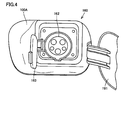
- Fig. 4 is a front view of charging portion 160.
- charging portion 160 includes an outer lid 161, a head portion 162, and an inner lid 163.
- Outer lid 161 opens and closes an opening formed in a rear fender of vehicle body 100A.
- Head portion 162 is provided in vehicle body 100A.
- Inner lid 163 covers an end surface of head portion 162.
- Head portion 162 is formed in a columnar shape. A plurality of holes receiving respective terminals provided in charge connector 100C and a cylindrical portion are formed in an end surface of head portion 162. As described above, connection portion 102C of charge connector 100C is formed in a hollow cylindrical shape. Thus, connection portion 102C can receive head portion 162. As head portion 162 enters connection portion 102C, each terminal of charge connector 100C enters the hole formed in head portion 162. Charging through charge connector 100C is thus allowed.
- the charge connector is supported by a support arm, for example, in order to achieve a gravity compensation function which will be described later.
- the support arm is folded while it is not in use (during a period in which charging is not performed) and it is extended while it is in use (during a period in which charging is performed).
- the folded state during a period in which the support arm is not in use is referred to as an "accommodated state”
- the extended state during a period in which the support arm is in use is referred to as a "used state”.
- Fig. 5 shows an accommodated state of the support arm
- Fig. 6 shows a specifications state of the support arm.
- a support arm 1 includes a base 10, a first parallelogram linkage mechanism 20, a second parallelogram linkage mechanism 30, an intermediate member 40A, and a tip end member 40B.
- Charge connector 100C is fixed to tip end member 40B.
- an articulated parallelogram linkage mechanism support arm supporting charge connector 100C is constructed.
- support arm 1 will now be described more specifically with reference to Figs. 5 and 6 .
- First parallelogram linkage mechanism 20 includes a first arm 21, a second arm 22, a pulley 23, and an elastic member 24.
- First arm 21 includes a base portion 21A and a tip end portion 21B.
- Base portion 21A is pivotably connected to base 10.
- Tip end portion 21B is pivotably connected to intermediate member 40A.
- Second arm 22 includes a base portion 22A and a tip end portion 22B.
- Base portion 22A is pivotably connected to intermediate member 40A.
- Tip end portion 22B is pivotably connected to base 10.
- First arm 21 and second arm 22 are each formed substantially in an L shape.
- Base portions 21A, 22A are each constructed by a short-side portion of the L shape, and tip end portion 22B is constructed by a long-side portion of the L shape.
- Tip end portion 21B of first arm 21 and base portion 22A of second arm 22 are formed in a manner vertically aligned on intermediate member 40A.
- a direction of extension of the long-side portion of the L shape of first arm 21 perpendicularly crosses a direction of extension of the short-side portion of the L shape of second arm 22. Then, a tip end of the long-side portion of the L shape of first arm 21 is opposed to the short-side portion of the L shape of second arm 22.
- Base portion 21A of first arm 21 and tip end portion 22B of second arm 22 are formed in a manner vertically aligned on base 10.
- a direction of extension of the long-side portion of the L shape of first arm 21 perpendicularly crosses a direction of extension of the short-side portion of the L shape of first arm 21.
- a tip end of the long-side portion of the L shape of second arm 22 is opposed to the short-side portion of the L shape of first arm 21.
- first parallelogram linkage mechanism 20 two L-shaped arms 21, 22 are combined with each other.
- Pulley 23 is fixed to first arm 21. Pulley 23 is provided such that the center of pulley 23 is located on a straight line connecting a pivot center of first arm 21 with respect to base 10 (a black circle in Fig. 5 ) and a pivot center of first arm 21 with respect to intermediate member 40A (similarly, a black circle in Fig. 5 ) to each other. In order to achieve the gravity compensation function which will be described later, pulley 23 should be located as such.
- a wire is connected to opposing sides (opposing ends) of elastic member 24 and the wire is wound around pulley 23.
- the wire provided on the opposing sides of elastic member 24 is fixed to a fixation portion 24A on base 10 and a fixation portion 24B on intermediate member 40A.
- Pulley 23 and wire 24 are members for constructing a gravity compensation apparatus which will be described later.
- Second parallelogram linkage mechanism 30 includes a third arm 31, a fourth arm 32, a pulley 33, and an elastic member 34.
- Third arm 31 includes a base portion 31A and a tip end portion 31B.
- Base portion 31A is pivotably connected to intermediate member 40A.
- Tip end portion 31B is pivotably connected to tip end member 40B.
- Fourth arm 32 includes a base portion 32A and a tip end portion 32B.
- Base portion 32A is pivotably connected to tip end member 40B.
- Tip end portion 32B is pivotably connected to intermediate member 40A.
- Third arm 31 and fourth arm 32 are each formed substantially in an L shape.
- Base portions 31A, 22A are each constructed by a short-side portion of the L shape and tip end portion 32B is constructed by a long-side portion of the L shape.
- Tip end portion 31B of third arm 31 and base portion 32A of fourth arm 32 are formed in a manner vertically aligned on tip end member 40B.
- a direction of extension of the long-side portion of the L shape of third arm 31 perpendicularly crosses a direction of extension of the short-side portion of the L shape of fourth arm 32. Then, a tip end of the long-side portion of the L shape of third arm 31 is opposed to the short-side portion of the L shape of fourth arm 32.
- Base portion 31A of third arm 31 and tip end portion 32B of fourth arm 32 are formed in a manner vertically aligned on intermediate member 40A.
- a direction of extension of the long-side portion of the L shape of third arm 31 perpendicularly crosses a direction of extension of the short-side portion of the L shape of fourth arm 32. Then, a tip end of the long-side portion of the L shape of fourth arm 32 is opposed to the short-side portion of the L shape of third arm 31.
- Pulley 33 is fixed to fourth arm 32. Pulley 33 is provided such that the center of pulley 33 is located on a straight line connecting a pivot center of fourth arm 32 with respect to intermediate member 40A (a black circle in Fig. 5 ) and a pivot center of fourth arm 32 with respect to tip end member 40B (similarly, a black circle in Fig. 5 ) to each other. In order to achieve the gravity compensation function which will be described later, pulley 33 should be located as such.
- a wire is connected to opposing sides (opposing ends) of elastic member 34 and the wire is wound around pulley 33.
- the wire provided on the opposing sides of elastic member 34 is fixed to a fixation portion 34A on intermediate member 40A and a fixation portion 34B on tip end member 40B.
- Pulley 33 and wire 34 are members for constructing a gravity compensation apparatus which will be described later.
- a gravity compensation apparatus included in support arm 1 will now be described.
- Fig. 6 a state where parallelogram linkage mechanisms 20, 30 are horizontal
- Fig. 5 a state where parallelogram linkage mechanisms 20, 30 are vertical
- centers of gravity of first parallelogram linkage mechanism 20, second parallelogram linkage mechanism 30 and intermediate member 40A should be displaced upward against gravity acting on first parallelogram linkage mechanism 20, second parallelogram linkage mechanism 30 and intermediate member 40A.
- This is gravity compensation intended in the present embodiment.
- first parallelogram linkage mechanism 20 and second parallelogram linkage mechanism 30 each have a structure in which two L-shaped arms are combined with each other.
- a link including two arms By thus constructing a link including two arms, a structure of lighter weight and higher durability than a support arm including a single arm can be obtained.
- a movable range is restricted as shown in Fig. 7 .
- a dashed line in Fig. 7 when the parallelogram linkage mechanism is close to a vertical state (that is, the accommodated state of the support arm), two arms interfere with each other and a completely accommodated state is not attained. Consequently, an effect of forming a foldable support arm (an effect to reduce an installation space) is not sufficiently obtained.
- first parallelogram linkage mechanism 20 and second parallelogram linkage mechanism 30 can be completely vertical in the accommodated state of the support arm as shown in Fig. 5 . Consequently, an effect of forming a foldable support arm (an effect to reduce an installation space) can sufficiently be obtained.
- arms 21, 22 constructing first parallelogram linkage mechanism 20 and arms 31, 32 constructing the second parallelogram linkage mechanism are identical in shape
- the shape of arms 21, 22 may be different from the shape of arms 31, 32 (a second shape).
- support arm 1 includes base 10, intermediate member 40A, tip end member 40B, first parallelogram linkage mechanism 20 provided between base 10 and intermediate member 40A and including first arm 21 and second arm 22, and second parallelogram linkage mechanism 30 provided between intermediate member 40A and tip end member 40B and including third arm 31 and fourth arm 32.
- First arm 21, second arm 22, third arm 31, and fourth arm 32 are each formed in the L shape.
- First arm 21 has base portion 21A constructed by the short-side portion of the L shape and serving as a "first base portion” pivotably connected to base 10 and tip end portion 21B constructed by the long-side portion of the L shape and serving as a "first tip end portion” pivotably connected to intermediate member 40A.
- Second arm 22 has base portion 22A constructed by the short-side portion of the L shape and serving as a "second base portion” pivotably connected to intermediate member 40A and tip end portion 22B constructed by the long-side portion of the L shape and serving as a "second tip end portion” pivotably connected to base 10.
- Tip end portion 21B and tip end portion 22B are provided to be opposed in a vertical direction to base portion 22A and base portion 21A, respectively.
- First parallelogram linkage mechanism 20 includes pulley 23 fixed to first arm 21 and elastic member 24 fixed to base 10 and intermediate member 40A.
- Elastic member 24 is provided to reach fixation portion 24B serving as a "second end portion” provided in a portion in intermediate member 40B where first arm 21 is connected from fixation portion 24A serving as a "first end portion” provided on base 10 around pulley 23.
- Third arm 31 has base portion 31A constructed by the short-side portion of the L shape and serving as a "third base portion” pivotably connected to intermediate member 40A and tip end portion 31B constructed by the long-side portion of the L shape and serving as a "third tip end portion” pivotably connected to tip end member 40B.
- Fourth arm 32 has base portion 32A constructed by the short-side portion of the L shape and serving as a "fourth base portion” pivotably connected to tip end member 40B and tip end portion 32B constructed by the long-side portion of the L shape and serving as a "fourth tip end portion” pivotably connected to intermediate member 40A. Tip end portion 31B and tip end portion 32B are provided to be opposed in a vertical direction to base portion 32A and base portion 31A, respectively.
- Second parallelogram linkage mechanism 30 includes pulley 33 serving as a "second pulley” fixed to fourth arm 32 and elastic member 34 serving as a "second elastic member” fixed to intermediate member 40A and tip end member 40B.
- Elastic member 34 is provided to reach fixation portion 34B serving as a "fourth end portion” provided in a portion of tip end member 40B where fourth arm 32 is connected from fixation portion 34A serving as a "third end portion” provided on intermediate member 40A around pulley 33.
- a direction in which tip end portion 21B and tip end portion 22B are opposed to base portion 22A and base portion 21A respectively is not limited to the vertical direction and it may be, for example, a lateral direction.
- a direction in which tip end portion 31B and tip end portion 32B are opposed to base portion 32A and base portion 31A respectively is not limited to the vertical direction and it may be, for example, a lateral direction.
- pulley 23, 33 is attached only to first arm 21 or fourth arm 32, but a pulley may be attached also to second arm 22 and third arm 31.
- first arm 21 has an adjustment hole 26 (elongated hole) extending in a direction in which first arm 21 extends.
- Pulley 23 is attached on adjustment hole 26.
- first arm 21 has an adjustment member 25 (a bolt).
- a bearing 27 is interposed between first arm 21 and bolt 25, so that bolt 25 can smoothly be turned.
- pulley 23 should be provided such that the center of pulley 23 is located on the straight line connecting the pivot center of first arm 21 with respect to base 10 (the black circle in Fig. 5 ) and the pivot center of first arm 21 with respect to intermediate member 40A (similarly, the black circle in Fig. 5 ) to each other.
- above-described adjustment member 25 and adjustment hole 26 serving as the "adjustment mechanism" are provided so that a position of pulley 23 on first arm 21 can readily be adjusted and hence adjustment of a position of pulley 23 for gravity compensation can be made in a simplified manner.
- a "second adjustment mechanism" adjustment hole 36 (naturally, also an adjustment member) may be provided also in fourth arm 32 to which pulley 33 is attached, as in first arm 21.
- Fig. 10 is a cross-sectional view along X-X in Fig. 9 .
- a guide portion 28 guiding movement of pulley 23 in a direction in which the arm extends (the direction of the long-side of the L shape) is provided.
- the guide portion may be in such a shape as that of a guide portion 29 shown in Fig. 11 .
- the support arm according to the present variation is characterized by providing a gravity center adjustment member 50 in each of first parallelogram linkage mechanism 20 and second parallelogram linkage mechanism 30.
- Gravity center adjustment member 50 has such a structure that a liquid is accommodated in a housing.
- a position of gravity center of the elastic member and a position of gravity center of gravity center adjustment member 50 coincide with each other in the horizontal direction (a state on the left in Fig. 13 ).
- the gravity center of the elastic member and the gravity center of gravity center adjustment member 50 are displaced in directions opposite to each other (arrows "m1g", “m2g” in Fig. 13 indicating gravity acting on each of the elastic member and gravity center adjustment member 50).
- gravity center adjustment member 50 has a function to cancel displacement of the gravity center of the elastic member due to pivoting of the arms of the parallelogram linkage mechanism. Consequently, regardless of a state of pivot of the arms, complete gravity compensation at all positions can be achieved.
- the first to fourth arms each have a length from 1 to 2 m and a weight of approximately 2 kg, and the elastic member has a weight of approximately 1 kg. Therefore, displacement of the gravity center due to pivoting of the arms affects gravity compensation and cancellation of displacement of the gravity center by means of gravity center adjustment member 50 is technically significant.
- gravity center adjustment member 50 By providing gravity center adjustment member 50 movably along a direction of the long side of the arm, gravity center adjustment member 50 can be moved to positively pivot the arms. Therefore, the arms can also be set from the used state to the accommodated state simply by moving gravity center adjustment member 50.
- Fig. 13 shows an arm of the parallelogram linkage mechanism not in the L shape but in the I shape, however, the arm in the L shape can naturally achieve an effect exactly the same as above.
- Fig. 13 shows only a single parallelogram linkage mechanism, however, gravity center adjustment member 50 is provided in both of first parallelogram linkage mechanism 20 and the second parallelogram linkage mechanism as described above.
- gravity center adjustment member 50 should be designed such that H representing a distance between fulcrums O1 and 02 shown in Fig. 14 , R representing a distance between fulcrums O1 and 03, S representing a distance between fulcrums 02 and 03, x1 representing a distance between fulcrum 04 and a position of gravity center of gravity center adjustment member 50, x2 representing a distance between fulcrum O1 and a position of gravity center of the elastic member, m1 representing a mass of gravity center adjustment member 50, m2 representing a mass of the elastic member, and ⁇ representing an angle of the arm with respect to the horizontal line satisfy relation below.
- Equation 2 as organized with regard to x1 will be Equation 3.
- Equation 2 as organized with regard to x1 will be Equation 3.
- Equation 4 A + H 2 + R 2 - S 2
- x ⁇ 1 2 ⁇ A cos ⁇ - A - H 2 + R 2 - S 2
- the gravity center adjustment member should only be designed such that Equation 5 is satisfied.
- gravity center adjustment member 50 is constructed such that a liquid 52 is accommodated in a case 51 as shown in Fig. 15A .
- the gravity center of the gravity center adjustment member is displaced.
- an amount of displacement of the gravity center of gravity center adjustment member 50 is desired to be greater, such a variation that case 51 is extended in a lateral direction in Fig. 15A or a bottom of case 51 at the central position of case 51 is raised as shown in Fig. 15B is possible. By doing so, a larger amount of liquid flows in a direction of inclination of the arm.
- gravity center adjustment member 50 may be attached to a lower arm in first parallelogram linkage mechanism 10 and second parallelogram linkage mechanism 20 as shown in Fig. 12 or to an upper arm as shown in Figs. 13 , 14 .
- load imposed on the upper arm can be reduced and the upper arm can be smaller in thickness and lighter in weight.
- FIG. 16 to 19 A third variation of the support arm according to the present embodiment will now be described with reference to Figs. 16 to 19 .
- the support arm according to the present variation is characterized by providing an accommodation assistance mechanism 60 assisting an operation for accommodating the support arm.
- Accommodation assistance mechanism 60 includes a weight member 62 connected to tip end member 40B, a first carrier portion 11 and a second carrier portion 12 each of which can carry weight member 62, and a carrier 61 provided on second parallelogram linkage mechanism 20 and serving as a "third carrier portion" capable of carrying weight member 62.
- Fig. 16 shows a state in which the support arm according to the present variation is accommodated. In this state, weight member 62 is carried on first carrier portion 11.
- Fig. 17 is a diagram showing a state in which transition from the accommodated state to the used state of the support arm is made. As shown in Fig. 17 , by moving weight member 62 from first carrier portion 11 to carrier 61, first parallelogram linkage mechanism 10 and second parallelogram linkage mechanism 20 enter the horizontal state as shown in Fig. 18 . This state is the used state of the support arm.
- weight member 62 is moved from carrier 61 to second carrier portion 12.
- tip end member 40B and charge connector 100C enter such a state as being lifted upward.
- the fulcrum of first parallelogram linkage mechanism 10 on base 10 side is locked.
- the state returns to the state in Fig. 16 (the state where the support arm is accommodated).
- the support arm in the present variation, can return from the used state to the accommodated state with such a simple operation as relocating weight member 62. Therefore, the support arm being left in the used state after charge connector 100C is used can be suppressed.
- the present invention is applicable to a support arm supporting a charge connector for a hybrid vehicle or the like.
Landscapes
- Engineering & Computer Science (AREA)
- Mechanical Engineering (AREA)
- Robotics (AREA)
- Power Engineering (AREA)
- Transportation (AREA)
- Manipulator (AREA)
- Toys (AREA)
- Vehicle Body Suspensions (AREA)
Applications Claiming Priority (1)
| Application Number | Priority Date | Filing Date | Title |
|---|---|---|---|
| PCT/JP2010/057551 WO2011135689A1 (ja) | 2010-04-28 | 2010-04-28 | サポートアーム |
Publications (1)
| Publication Number | Publication Date |
|---|---|
| EP2565150A1 true EP2565150A1 (en) | 2013-03-06 |
Family
ID=44861033
Family Applications (1)
| Application Number | Title | Priority Date | Filing Date |
|---|---|---|---|
| EP10838393A Withdrawn EP2565150A1 (en) | 2010-04-28 | 2010-04-28 | Support arm |
Country Status (5)
| Country | Link |
|---|---|
| US (1) | US20130062476A1 (ja) |
| EP (1) | EP2565150A1 (ja) |
| JP (1) | JP5263396B2 (ja) |
| CN (1) | CN102307709A (ja) |
| WO (1) | WO2011135689A1 (ja) |
Families Citing this family (4)
| Publication number | Priority date | Publication date | Assignee | Title |
|---|---|---|---|---|
| JP5376065B2 (ja) | 2010-09-13 | 2013-12-25 | トヨタ自動車株式会社 | サポートアーム |
| US10471610B2 (en) * | 2015-06-16 | 2019-11-12 | Samsung Electronics Co., Ltd. | Robot arm having weight compensation mechanism |
| US20180193107A1 (en) * | 2017-01-12 | 2018-07-12 | Electronics And Telecommunications Research Institute | Balance arm apparatus for supporting heavy tools |
| CN110733056B (zh) * | 2019-11-01 | 2024-06-18 | 达闼机器人股份有限公司 | 机器人的多轴机械臂及其转接组件、机器人 |
Family Cites Families (7)
| Publication number | Priority date | Publication date | Assignee | Title |
|---|---|---|---|---|
| US4208028A (en) * | 1974-09-16 | 1980-06-17 | Garrett Brown | Support apparatus |
| DE3921857A1 (de) * | 1989-07-04 | 1991-01-17 | Wild Leitz Ag | Mit zusatzvorrichtungen ausgestattetes stativ fuer die halterung eines frei positionierbaren geraetes |
| US5249533A (en) * | 1991-07-18 | 1993-10-05 | Barudan America, Inc. | Sewing machine table |
| JP2545725B2 (ja) * | 1992-11-19 | 1996-10-23 | 工業技術院長 | 鍛造作業用ロボットの緩衝装置 |
| JP2003089090A (ja) * | 2001-09-17 | 2003-03-25 | Rikogaku Shinkokai | 多関節アーム機構 |
| JP4144021B2 (ja) | 2001-12-14 | 2008-09-03 | 学校法人早稲田大学 | 機械的自重補償装置 |
| EP1877636B1 (en) * | 2005-04-15 | 2012-12-26 | BROWN, Garrett W. | Equipoising support apparatus |
-
2010
- 2010-04-28 US US13/141,841 patent/US20130062476A1/en not_active Abandoned
- 2010-04-28 CN CN2010800038456A patent/CN102307709A/zh active Pending
- 2010-04-28 WO PCT/JP2010/057551 patent/WO2011135689A1/ja active Application Filing
- 2010-04-28 JP JP2011525326A patent/JP5263396B2/ja active Active
- 2010-04-28 EP EP10838393A patent/EP2565150A1/en not_active Withdrawn
Also Published As
| Publication number | Publication date |
|---|---|
| JP5263396B2 (ja) | 2013-08-14 |
| US20130062476A1 (en) | 2013-03-14 |
| CN102307709A (zh) | 2012-01-04 |
| JPWO2011135689A1 (ja) | 2013-07-18 |
| WO2011135689A1 (ja) | 2011-11-03 |
Similar Documents
| Publication | Publication Date | Title |
|---|---|---|
| US8985537B2 (en) | Support arm | |
| JP4577413B2 (ja) | 車両 | |
| US10486514B2 (en) | Vehicle with distributed drive and power components | |
| US8561737B2 (en) | Charging cable-housing device and vehicle | |
| EP2565150A1 (en) | Support arm | |
| JP4858203B2 (ja) | 自動車 | |
| US9963028B1 (en) | Battery support structure for electrified vehicle | |
| CN108501676A (zh) | 牵引电池固定总成和方法 | |
| KR101800392B1 (ko) | 승객 좌석을 고정하는 돌출 박스 구조를 구비한 섀시 | |
| EP2763257A1 (en) | Cable winding device | |
| AU2006300197B2 (en) | Structure for installing electrical part | |
| EP2767427A1 (en) | Structure for mounting electric power storage device | |
| CN107804149A (zh) | 车辆用设备的安装构造 | |
| KR20080107458A (ko) | 전원 팩 탑재 구조 | |
| JP2017196941A (ja) | 車両のバッテリ搭載構造 | |
| US10826034B2 (en) | Mounting clamps for securing groupings of battery cells | |
| JP7481221B2 (ja) | 燃料電池車両 | |
| US20200070610A1 (en) | Electrified vehicle with vibration isolator within frame and corresponding method | |
| US9166428B2 (en) | Charging device | |
| JP2021112986A (ja) | 蓄電装置の搭載構造 | |
| CN113165504A (zh) | 电动车辆及能量组件 | |
| EP4462568A1 (en) | A battery pack, a method and a vehicle | |
| KR102750546B1 (ko) | 차량용 충전 인렛 조립체 | |
| JP2021104759A (ja) | 車両 |
Legal Events
| Date | Code | Title | Description |
|---|---|---|---|
| PUAI | Public reference made under article 153(3) epc to a published international application that has entered the european phase |
Free format text: ORIGINAL CODE: 0009012 |
|
| 17P | Request for examination filed |
Effective date: 20110630 |
|
| AK | Designated contracting states |
Kind code of ref document: A1 Designated state(s): AT BE BG CH CY CZ DE DK EE ES FI FR GB GR HR HU IE IS IT LI LT LU LV MC MK MT NL NO PL PT RO SE SI SK SM TR |
|
| DAX | Request for extension of the european patent (deleted) | ||
| STAA | Information on the status of an ep patent application or granted ep patent |
Free format text: STATUS: THE APPLICATION HAS BEEN WITHDRAWN |
|
| 18W | Application withdrawn |
Effective date: 20131022 |