EP2565100B1 - Stroller - Google Patents
Stroller Download PDFInfo
- Publication number
- EP2565100B1 EP2565100B1 EP12177476.4A EP12177476A EP2565100B1 EP 2565100 B1 EP2565100 B1 EP 2565100B1 EP 12177476 A EP12177476 A EP 12177476A EP 2565100 B1 EP2565100 B1 EP 2565100B1
- Authority
- EP
- European Patent Office
- Prior art keywords
- stroller
- latches
- carriage frame
- movement
- positions
- Prior art date
- Legal status (The legal status is an assumption and is not a legal conclusion. Google has not performed a legal analysis and makes no representation as to the accuracy of the status listed.)
- Not-in-force
Links
Images


Classifications
-
- B—PERFORMING OPERATIONS; TRANSPORTING
- B62—LAND VEHICLES FOR TRAVELLING OTHERWISE THAN ON RAILS
- B62B—HAND-PROPELLED VEHICLES, e.g. HAND CARTS OR PERAMBULATORS; SLEDGES
- B62B7/00—Carriages for children; Perambulators, e.g. dolls' perambulators
- B62B7/04—Carriages for children; Perambulators, e.g. dolls' perambulators having more than one wheel axis; Steering devices therefor
- B62B7/06—Carriages for children; Perambulators, e.g. dolls' perambulators having more than one wheel axis; Steering devices therefor collapsible or foldable
- B62B7/08—Carriages for children; Perambulators, e.g. dolls' perambulators having more than one wheel axis; Steering devices therefor collapsible or foldable in the direction of, or at right angles to, the wheel axis
- B62B7/083—Carriages for children; Perambulators, e.g. dolls' perambulators having more than one wheel axis; Steering devices therefor collapsible or foldable in the direction of, or at right angles to, the wheel axis the wheel axes being moved from each other during folding
-
- B—PERFORMING OPERATIONS; TRANSPORTING
- B62—LAND VEHICLES FOR TRAVELLING OTHERWISE THAN ON RAILS
- B62B—HAND-PROPELLED VEHICLES, e.g. HAND CARTS OR PERAMBULATORS; SLEDGES
- B62B7/00—Carriages for children; Perambulators, e.g. dolls' perambulators
- B62B7/04—Carriages for children; Perambulators, e.g. dolls' perambulators having more than one wheel axis; Steering devices therefor
- B62B7/06—Carriages for children; Perambulators, e.g. dolls' perambulators having more than one wheel axis; Steering devices therefor collapsible or foldable
- B62B7/068—Carriages for children; Perambulators, e.g. dolls' perambulators having more than one wheel axis; Steering devices therefor collapsible or foldable by sliding a bushing along a rod, e.g. like folding means of an umbrella
-
- B—PERFORMING OPERATIONS; TRANSPORTING
- B62—LAND VEHICLES FOR TRAVELLING OTHERWISE THAN ON RAILS
- B62B—HAND-PROPELLED VEHICLES, e.g. HAND CARTS OR PERAMBULATORS; SLEDGES
- B62B7/00—Carriages for children; Perambulators, e.g. dolls' perambulators
- B62B7/04—Carriages for children; Perambulators, e.g. dolls' perambulators having more than one wheel axis; Steering devices therefor
- B62B7/06—Carriages for children; Perambulators, e.g. dolls' perambulators having more than one wheel axis; Steering devices therefor collapsible or foldable
- B62B7/08—Carriages for children; Perambulators, e.g. dolls' perambulators having more than one wheel axis; Steering devices therefor collapsible or foldable in the direction of, or at right angles to, the wheel axis
-
- B—PERFORMING OPERATIONS; TRANSPORTING
- B62—LAND VEHICLES FOR TRAVELLING OTHERWISE THAN ON RAILS
- B62B—HAND-PROPELLED VEHICLES, e.g. HAND CARTS OR PERAMBULATORS; SLEDGES
- B62B2205/00—Hand-propelled vehicles or sledges being foldable or dismountable when not in use
- B62B2205/003—Hand-propelled vehicles or sledges being foldable or dismountable when not in use with actuation mechanisms which drive the folding or unfolding operation
-
- B—PERFORMING OPERATIONS; TRANSPORTING
- B62—LAND VEHICLES FOR TRAVELLING OTHERWISE THAN ON RAILS
- B62B—HAND-PROPELLED VEHICLES, e.g. HAND CARTS OR PERAMBULATORS; SLEDGES
- B62B2205/00—Hand-propelled vehicles or sledges being foldable or dismountable when not in use
- B62B2205/12—Collapsible wheels
-
- B—PERFORMING OPERATIONS; TRANSPORTING
- B62—LAND VEHICLES FOR TRAVELLING OTHERWISE THAN ON RAILS
- B62B—HAND-PROPELLED VEHICLES, e.g. HAND CARTS OR PERAMBULATORS; SLEDGES
- B62B2205/00—Hand-propelled vehicles or sledges being foldable or dismountable when not in use
- B62B2205/18—Geared articulations
-
- B—PERFORMING OPERATIONS; TRANSPORTING
- B62—LAND VEHICLES FOR TRAVELLING OTHERWISE THAN ON RAILS
- B62B—HAND-PROPELLED VEHICLES, e.g. HAND CARTS OR PERAMBULATORS; SLEDGES
- B62B9/00—Accessories or details specially adapted for children's carriages or perambulators
- B62B9/10—Perambulator bodies; Equipment therefor
-
- B—PERFORMING OPERATIONS; TRANSPORTING
- B62—LAND VEHICLES FOR TRAVELLING OTHERWISE THAN ON RAILS
- B62B—HAND-PROPELLED VEHICLES, e.g. HAND CARTS OR PERAMBULATORS; SLEDGES
- B62B9/00—Accessories or details specially adapted for children's carriages or perambulators
- B62B9/24—Safety guards for children, e.g. harness
Definitions
- the present invention relates generally to strollers, and more particularly pertains to baby strollers having one or more components which can be moved by a drive mechanism such as foldable baby strollers which may be moved between collapsed and operative positions automatically with little effort.
- Baby strollers also referred to as baby carriages, baby buggies or prams, have been used to hold and transport babies and young children for many years.
- Early baby strollers had parts which were fixedly secured to one another such that they did not fold for compactness.
- baby strollers have been designed to have some parts which are movable relative to one another to allow movement of some parts of the stroller to achieve a more compact configuration when not in use.
- current strollers do not allow for movement or folding to as compact of a configuration as desired, and arc cumbersome and sometimes difficult to move between their collapsed (closed) position and their open (operative) positions, particularly when attending to a baby or child.
- a stroller which is easier to move between its collapsed and operative positions is desired.
- WO 2004/039653 A1 discloses a pivotable stroller comprising an electric motor-driven pivot drive for adjusting the inclination of a backrest.
- a stroller comprising:
- the collapsible carriage frame includes an interior portion.
- the stroller further comprises an object sensor configured to detect the presence of objects within the interior portion of the collapsible carriage frame and send a signal to prevent actuation of the drive mechanism if an object is detected in the interior portion of the collapsible carriage frame.
- the object sensor sends a signal to a display to provide a visual indication to a user if an object is present in the interior portion.
- the stroller further comprises at least one position sensor provided at a selective location on the collapsible carriage frame to send a signal indicative of the positions of at least one of the collapsible carriage frame to the control system.
- the at least one position sensor sends the signal to a display to provide at least one of a visual indication and an audio indication to a user as to a current position of the collapsible carriage frame.
- the stroller further comprises one or more latch position sensors which detect when the one or more latches are in their latched positions, with the one or more latch position sensors sending a signal to stop actuation of the one or more latch drive mechanisms upon receipt of the signal.
- the stroller further comprises a display (96) and one or more latch position sensors which detect when the one or more latches are in their latched positions, with the one or more latch position sensors sending a signal to the display when the one or more latches are in their latched positions, with the display providing visual confirmation to the user that the one or more latches are in their latched positions.
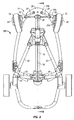
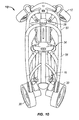
- FIGS. 1 through 16 A stroller embodying various aspects of the present invention is shown in FIGS. 1 through 16 . It will be readily apparent to those skilled in the art, however, that the stroller of FIGS. 1 through 16 represents but one of a wide variety of structures, configurations and modes of operation of strollers which fall within the scope of the present invention.
- a stroller 10 which comprises a pair of front wheels 12 having a front wheel support structure 14 for supporting the front wheels 12.
- the front wheel support structure 14 is slidably engaged with a guide rail 16 for sliding movement of the the front collar portion 26 of the front wheel support structure 14 along the longitudinal axis 18 (see FIGS. 11-13 ) of the guide rail 16.
- the front wheel support structure 14 has members 20, 20a, 22, 24 and 26 which arc movable between an open position (see FIGS. 1-4 ) and a collapsed position (see FIGS. 7-10 ) upon movement of the front collar 26 of the front wheel support structure 14 along the longitudinal axis 18 of the guide rail 16.
- the illustrated front wheel support structure 14 comprises a pair of generally U-shaped wheel receiving members 20 for receiving respective wheels 12, and axles 20a to allow the wheels 12 to roll about their respective axles 20a.
- the front wheel receiving members 20 are pivotally connected to a first end 22a of front wheel connector 22 to allow the wheels 12 to pivot about respective axes substantially parallel to their axes 20a to accommodate changes in the rolling direction of the front of the stroller.
- the second end 22b of the front wheel connector 22 is pivotally connected to the front collar 26.
- Struts 24 are pivotally connected at a first end 24a to the front wheel connector 22, and the struts 24 are pivotally connected at a second end 24b to the front abutment plate 29.
- the front wheel connector 22, strut 24 and front collar 26 form a linkage whereby the front wheels 12 and their associated front wheel support structure 14 are movable between their collapsed positions ( FIGS. 7-10 ) and their open positions ( FIGS 1-4 ) upon movement of the front collar 26 along the longitudinal axis 18 of the guide rail 16.
- a front abutment plate 29 is fixedly connected to the front end 16a of the guide rail 16 and receives the front wheel connectors 22 when the front wheel support structure 14 is in its fully open position, such that when the stroller 10 is in its fully open position the front wheel members 22 are secured between the front abutment member 29 and the front wheel connector securing portion 28 of the front collar 26 as shown in FIG. 1 .
- a pair of seat support arms 94 are provided to support a seat (not shown).
- the stroller 10 further comprises a pair of rear wheels 30 having a rear wheel support structure 32 for supporting the rear wheels 30.
- the rear wheel support structure 32 is slidably engaged with the guide rail 16 for sliding movement of the rear collar portion 34 of the rear wheel support structure 32 along the longitudinal axis 18 of the guide rail 16.
- the rear wheel support structure 32 has members 34, 36, 38 and 40 which are movable between an open position (see FIGS. 1-4 ) and a collapsed position (see FIGS. 7-10 ) upon movement of the rear collar 34 of the rear wheel support structure 32 along the longitudinal axis 18 of the guide rail 16.
- the rear wheel support structure 32 of stroller 10 comprises a rear axle supporting member 36 at each of the rear wheels 30 for supporting the respective axles 31 of the rear wheels 30 to allow the rear wheels 30 to roll about their respective axles 31.
- the rear axle support members 36 preferably each have a braking mechanism of the type well known in the art for selectively locking the rear wheels to prevent inadvertent rolling movement of the stroller when the braking mechanism is locked.
- the rear axle support members 36 are fixedly connected to the rear ends 40a of the rear legs 40, with the front ends 40b of the rear legs 40 pivotally connected to the central collar 42 which is attached in a fixed position to the guide rail 16.
- the guide rail may be configured to define a suitable mounting position for the central collar 42, and to maintain the central collar 42 at a suitable longitudinal position along the guide rail 16.
- the rear ends 40a of the rear legs 40 are pivotally connected to the lower ends 38a of the rear wheel connectors 38 through brackets 44, with the upper ends 38b of the rear wheel connectors 38 pivotally connected to the rear member securing portion 46 of the rear collar 34. Accordingly, the rear wheel connector 38, rear leg 40 and rear collar 34 form a linkage whereby the rear wheels 30 and their associated rear wheel support structure 32 are movable between their collapsed positions ( FIGS. 7-10 ) and their open positions ( FIGS 1-4 ) upon movement of the rear collar 34 along the longitudinal axis 18 of the guide rail 16.
- the rear member securing portion 46 of the rear collar 34 has a pair of recesses for receiving the upper ends 38b of the rear wheel connectors 38, and a rear abutment member 48 is fixedly connected to the rear end 16b of the guide rail 16 such that when the stroller 10 is in its fully open position the upper ends 38b of the rear wheel connectors 38 are secured between the rear abutment member 48 and the rear member securing portion 46 of the rear collar 34.
- a generally U-shaped frame member comprised of two separate lateral frame components 50 is pivotally connected to the front end 16a of the guide rail 16 through a frame mounting portion 52 of the front abutment member 29, to allow each of the lateral frame components 50 to pivot or rotate relative to the front abutment member 29.
- a pair of arcuate frame supporting members 54 each have a lower end 54b pivotally connected to the rear member securing portion 46 of the rear collar 34 and an upper end 54a pivotally connected to a respective upper end 50a of the two lateral frame members 50.
- the rear member securing portion 46 of the rear collar 34 has a pair of recesses for receiving the respective lower ends 54b of the frame supporting members 54 when the rear collar 34 is in its fully open position. Hence, when the rear collar 34 is in its fully open position the lower ends 54b of the frame supporting members 54 are secured between the rear member securing portion 46 of the rear collar 34 and the rear abutment member 48.
- a generally U-shaped handle bar is provided comprised of two lateral handle bar components 56 having lower ends 56a pivotally connected to respective upper ends 50a of the frame member. Adjacent the upper end 56b of one of the lateral handle bar components 56 an elongated slot 57 is provided, and adjacent the upper end 56b of the other lateral handle bar component 56 a suitable pin 59 is provided which is slidably received and retained within the slot 57 of the other lateral handle bar component 56. This slidable linkage allows the upper ends 56b of the lateral handle bar components 56 to move toward and away from one another (as seen in comparing FIGS.
- the handle bars have an inclined portion adjacent their ends at the area in which the upper end portions of the handle bar members overlap to facilitate sliding and overlapping movement of the end portions without requiring pivotal movement of either of the lateral handle bar members.
- the two lateral handle bar components 56 act as a single generally U-shaped handlebar when the two lateral handle bar components 56 are in their open positions as in FIG. 1 at which they function as a single handle bar unit due to the pin-in-slot linkage maintaining the upper ends 56b of the two lateral handle bar components 56 connected together.
- two lateral handle bar components which are not permanently interconnected at their upper ends may be utilized. It may be desirable to provide a handle bar latch mechanism (not shown) which engages the upper ends 56b of the two lateral handle bar components 56 to retain them interconnected when the handle bar components 56 are in their open position, but which allows release of the two lateral handle bar components 56 to allow them to move independently of one another when not in their open position.
- the release of the handle bar latch mechanism may be automated so that the latch mechanism releases or unlatches upon actuation of a control switch or a controller.
- the stroller may be constructed such that release of the handle bar latch mechanism, either manually or automatically, may actuate automatic movement of one or more additional stroller components as suitable.
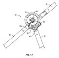
- each of the two lateral handle bar components 56 and the frame supporting members 54 are pivotally connected to the upper ends 50a of the frame member. More specifically, the frame supporting member 54 has a frame gear member 58 fixed thereto such that upon pivoting movement of the frame supporting members 54 relative to the frame member 50 about pivot pin 60 the frame gear member 58 pivots about pivot pin 60 in the same rotational direction.
- the ends 56a of the handle bar 56 have handle bar gear members 62 fixed thereto and in engagement with the frame gear member 58 such that upon pivotal movement of the frame supporting members 54 relative to the frame member 50 the handle bar components 56 are pivoted relative to the frame member 50. This defines a simultaneous folding and unfolding gear arrangement referred to generally at 51.
- the frame gear member 58 pivots about pivot pin 60 which rotates the handle bar gear member 62 which pivots both of the handle bar components 56 forward from the open position of FIG. 14 to the partially open position of FIG. 15 .
- the gears and handle bar components are configured such that upon movement of the frame supporting members 54 to their fully collapsed positions relative to the frame members 50 as shown in FIG. 16 , the handle bar components 56 are moved to their fully collapsed positions as shown in FIG. 16 .
- the handle bar components 56 are moved through the gear arrangement toward its fully open position as well.
- gear arrangement 51 may be used to achieve the desired movement of the handle bar 56 to its fully collapsed position upon movement of the frame supporting members 54 to their fully collapsed position, and to achieve the desired movement of the handle bar 56 to its fully open position upon movement of the frame supporting members 54 to their fully open position, a variety of other arrangements may be used in addition to, or instead of, gears for achieving this, such as mechanical linkages, a drive mechanism in operative engagement with the handle bars, cable connections, pneumatics, and others.
- the handle bar gear member 62 resides within a gear housing 64, and frame gear member 58 resides within frame gear member enclosure 66 which also accommodates a portion of the gear housing therein, so the frame gear member 58 and handle bar gear member 62 are covered at all times throughout collapsing, opening and use of the stroller.
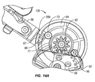
- a latch member 67 is provided at the end 56b of the lateral handle bar component 56 which is spring biased to its extended position extending outwardly from the end 56b, as shown in FIG. 14A .
- the latch member 67 is movable to a retracted position not extending outwardly from the end 56b.
- a recess 69 for receiving the latch member 67 when it is in its extended position is provided in the gear housing 64 to receive and engage the latch member 67 therein, and thereby engage the handle bar member 56.
- the latch member 67 can be released from the recess 69 by moving the latch to its retracted position to disengage the latch member 67 and thereby disengage the handle bar member 56 to allow rotational movement of the handle bar member and accordingly allow movement of the stroller toward its collapsed position.
- An arcuate slot 71 is provided in the gear housing 64 which slidably receives and retains a pin or rivet 73 on the frame member 50 to limit the extent of pivotal movement of the frame member 50 relative to the handle bar component 56 to provide alignment of the recess 69 with the latch member 67 to assure the latch member is properly received and engaged in the recess 69 when the stroller is in its open position and the latch member 67 is spring biased into the recess 69.
- the end 56b is arcuate to correspond to the arcuate or circular perimeter of the gear housing 64, whereby after the latch has been disengaged and the stroller has been moved to its collapsed position, upon movement of the stroller toward its open position the latch member 67 is spring biased against the arcuate perimeter of the gear housing 64 until the stroller is fully open, at which point the latch member 67 is aligned with, and spring biased into, the recess 69 to prevent movement of the stroller toward its collapsed position until the latch member 67 is retracted.
- the stroller 10 has a drive mechanism 70 through which the stroller 10 may be moved back and forth between its open and collapsed positions.
- a rear threaded member 72 is mounted in the guide rail 16 for rotation within the guide rail interior about the longitudinal axis of the rear threaded member, with the longitudinal axis of the rear threaded member being coaxial with the longitudinal axis 18 of the guide rail.
- the rear threaded member 72 is supported by bearings 74a and 74b at each end thereof, and a threaded member pulley 76 is fixedly connected to the rear threaded member 72.
- a motor 78 is mounted in a fixed position on the guide rail and has a drive pulley 80 connected to its shaft and a belt (not shown) extends between the drive pulley 80 and threaded member pulley 76 through which the threaded member pulley 76 is rotated about its longitudinal axis upon actuation of the motor 78.
- a rear nut member 82 is in threaded engagement with the rear threaded member 72, with the rear nut member 82 having a mounting portion 82a which extends outwardly of the guide rail 16 through the longitudinally extending slot 84 in the guide rail 16.
- the motor 78 effects rotation of the rear threaded member 72 through the belt and pulleys (with the lateral forces exerted on the threaded member pulley 76 by the belt being taken up by the bearings 74a and 74b) whereby the nut member 82 (which is prevented from rotating together with the rear threaded member 72 due to the mounting portion 82a of the rear nut member 82 extending outwardly of the slot 84 and bearing against the sides of the slot when the rear threaded member 72 rotates) is driven longitudinally along the rear threaded member 72.
- the rear collar 34 is mounted to the mounting portion 82a of the rear nut member 82 such that the rear collar 34 and the rear member securing portion 46 connected thereto moves longitudinally along the guide rail 16 together with the rear nut member 82 as the rear threaded member 72 is rotated by the motor 78.
- the longitudinal movement of the rear collar 72 along the guide rail 16 thereby effects movement of the rear wheel support structure 32 between its collapsed and open positions, with the rear collar 34 moving in a first longitudinal direction along the guide rail 16 upon rotation of the rear threaded member 72 in first rotational direction, and the rear collar 34 moving in a second longitudinal direction along the guide rail 16 upon rotation of the rear threaded member 72 in an opposition, second rotational direction to move the rear wheel support structure between its collapsed and open positions.
- the drive mechanism 70 is operatively engaged with the rear wheel support structure 32 to move the rear wheels 30 between their collapsed and open positions.
- a front threaded member 86 is mounted in the guide rail 16 for rotation within the guide rail interior about the longitudinal axis of the front threaded member, with the longitudinal axis of the front threaded member being coaxial with the longitudinal axis 18 of the guide rail 16 in a manner similar to the rear threaded member 72.
- the rear end 86a of the front threaded member 86 is coupled to the rear threaded member 72 through coupling member 88 such that the front threaded member 86 and the rear threaded member 72 rotate together.
- the front end 86b of the front threaded member 86 is supported in a suitable recess in the rear side of the front abutment member which allows rotation of the front threaded member 86 about its longitudinal axis, which is coaxial with the longitudinal axis of the rear threaded member 72.
- a front nut member 90 is in threaded engagement with the front threaded member 86, with the front nut member 82 having a mounting portion 90a which extends outwardly of the guide rail 16 through the longitudinally extending slot 84 in the guide rail 16. Accordingly, as the motor 78 is actuated, the motor 78 effects rotation of the front threaded member 86 (simultaneously and in the same rotational direction as the rear threaded member 72) whereby the front nut member 90 (which is prevented from rotating together with the front threaded member 86 due to the mounting portion 90a of the front nut member 82 extending outwardly of the slot 84 and bearing against the sides of the slot when the front threaded member 86 rotates) is driven longitudinally along the front threaded member 86.
- the front collar 26 is mounted to the mounting portion 90a of the front nut member 90 such that the front collar 90 and the front wheel connector securing portion 28 connected thereto moves longitudinally along the guide rail 16 together with the front nut member 90 as the front threaded member 86 is rotated by the motor 78.
- the longitudinal movement of the front collar 26 along the guide rail 16 thereby effects movement of the front wheel support structure 14 between its collapsed and open positions, with the front collar 26 moving in a first longitudinal direction along the guide rail 16 upon rotation of the front threaded member 86 in first rotational direction, and the front collar 90 moving in a second longitudinal direction along the guide rail 16 upon rotation of the front threaded member 86 in an opposition, second rotational direction to move the front wheel support structure 14 between its collapsed and open positions.
- the drive mechanism 70 is operatively engaged with the front wheel support structure 14 to move the front wheels 12 between their collapsed and open positions.
- the front and rear threaded members 86 and 72 are coaxial and are coupled together so that they rotate simultaneously in the same direction. They also have opposite threads (not shown) such that when the front and rear threaded members 86 and 72 rotate together in a first rotational direction the front and rear collars 26 and 34 move toward one another to move the front and rear wheel support structures 14 and 32 toward their collapsed positions, and when the front and rear threaded members rotate together in a second, opposite rotational direction the front and rear collars 26 and 34 move away from one another to move the front and rear wheel support structures 14 and 32 toward their open positions.
- the threads of the front and rear threaded members 86 and 72 are different from each other, such that upon the same amount of rotational movement of the front and rear threaded members 86 and 72 the rear collar 34 is displaced a greater distance along the longitudinal axis 18 of the guide rail 16 than the front collar 26 is displaced along the longitudinal axis 18 of the guide rail 16 (with the simultaneous displacement of the front and rear collars 26 and 34 being in opposite directions).
- a single threaded member may be provided instead of two separate threaded members, with the single threaded member having two distinct, opposite thread portions.
- the stroller 10 provides a frame, a front wheel support structure, and a rear wheel support structure which define a linkage having a single degree of freedom, such that movement of any one of the coupled threaded members, front wheel support structure, or rear wheel support structure 34 relative to one another toward their collapsed or open positions may effect movement of the others toward their collapsed or open positions.
- the movement and/or securing in place of the front and rear wheel support structures may be achieved.
- the coupled threaded members, front wheel support structure, rear wheel support structure and handle bars form a linkage having a single degree of freedom, whereby by accurately controlling and/or preventing rotation of the coupled front and rear threaded members, the movement and/or securing in place of the handle bars, and the front and rear wheel support structures may be achieved.
- a control switch 92 is provided, preferably in the handle bar 56 for ease of access, for effecting actuation of the drive mechanism 70.
- the control switch 92 is operatively connected to the motor 78 (which may be through a controller, such as a microprocessor, not shown) to control actuation of the motor 78, which in turn controls the drive mechanism 70, which in turn controls movement of the front and rear wheel support members 14 and 32 between their collapsed and open positions.
- the wires extending between the control switch 92 and motor 78 are all disposed internally of the stroller elements, such as extending internally within hollow tubular members.
- the control switch 92 may also be operatively coupled to one or more latch mechanisms to move the latch mechanisms from their latched positions in which they prevent the stroller from moving from its fully open position toward its collapsed position, to their unlatched positions in which they allow the stroller to move from its fully open position towards its collapsed position.
- the motor 78 or a separate drive, may be operatively connected to a control switch and/or controller to effect automatic movement of the latches upon actuation by the control switch 94.
- the unlatching of the one or more latches is preferably carried out prior to, or simultaneous with the initiation actuation of the motor 78 and drive mechanism 70 of which the motor may be a part.
- a control switch may be provided at or in proximity with one or more latches on the stroller (or operatively engaged with one or more latches), such that upon, or subsequent to, manually unlatching the one or more latches the actuator is actuated to effect automatic movement of the desired one or more stroller components from a first position to a second position.
- a control switch such as a position sensing switch (which may be an optical switch, electrical contact switch, or any other type of switch) may be provided which is operatively engaged with a controller which controls the actuation of the drive mechanism as desired (which may be in any of a wide variety of rates, sequences, options, etc.)
- the control switch or switches may be located and configured to be triggered or actuated during conventional manual unlatching of the latch or latches, or may be at a convenient location on the stroller which allows the control switch to be easily actuated while, or immediately subsequent to, unlatching of the latch or latches. It may be desirable to provide an arrangement in which two or more control switches associated with respective latches are required to both be actuated to effect automatic movement of the desired one or more stroller components from a first position to a second position.
- a single control switch may actuate a single controller, such as a microprocessor, which in turn actuates two or more separate drive mechanisms.
- a single control switch may actuate two or more controllers which each in turn actuate one or more separate drive mechanisms.
- the stroller 10 may also have a display 96, such as on the handle bar 56, to provide information to the user as to any of a wide variety of information such as confirmation that the front and rear wheel support structures are secured in their fully open positions, that latches are locked, that a brake is engaged, ambient temperature, distance traveled, time, or the like.
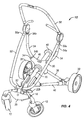
- FIGS. 17-20 a stroller 100 embodying various aspects of the present invention is illustrated.
- the stroller 100 is movable or foldable between a collapsed position (see FIG. 20 ) and an open or operative position (see FIGS. 17 and 18 ).
- An intermediate stroller position between collapsed and open is illustrated in FIG. 19 .
- the stroller 100 has a front wheel support structure 104 having a pair of laterally spaced front support legs 110 with front wheels 108 rotatably mounted thereon.
- the stroller 100 also has a rear wheel support structure 106 having a pair of laterally spaced rear support legs 112 with rear wheels 114 rotatably mounted thereon.
- the upper ends of the respective front support legs 100 and rear support legs 112 are pivotally connected to one another which allows the front and rear wheels 108 and 114 to pivot toward and away from one another.
- the stroller 100 also has a handlebar 116 with a pair of laterally spaced legs 118, which legs 118 are pivotally connected at their ends 118a to respective sides of the rear end 120a of a seat member 120 to allow pivotal movement between the seat member 120 and handlebar legs 118.
- the seat member 120 is also pivotally connected near its front end 120b to the front support legs 110 to allow pivotal movement between the seat member 120 and the front support legs 110.
- the stroller 100 has a pair of arms 122 (see FIG. 17 ) which are each pivotally connected at one of their ends to the handlebar legs 116 and pivotally connected to the rear support legs 112.
- a link 123 is provided extending between and pivotally connected to the lower end 118a of the handlebar and the rear support leg 112. Accordingly, the front support legs 110, rear support legs 112, seat member 120, arms 122, links 123 and handlebar 116 defme a linkage having a single degree of freedom, such that each of these components move simultaneously between their collapsed and open position, and such that prevention of motion of various components relative to each other prevents movement of the stroller between its collapsed and open positions.
- the link 123 facilitates the linkage mechanism of the stroller 100 as having a single degree of freedom, with left and right sides coupled together by cross braces.
- a locking mechanism or latch may be provided which, when moved to its locking or latched position, allows locking of the stroller 100 in its open position during use.
- a drive motor or mechanism 124 is operatively coupled to both the seat member 120 and front support legs 110 at their pivot axis such that, when actuated, the motor 124 pivots the seat member 120 relative to the front support legs 110 (as seen in comparing FIGS. 18 through 20 ). Because the linkage mechanism of the stroller 100 has a single degree of freedom, the pivoting of the seat 120 relative to the front support legs 110 by the motor 124 effects movement of each of the front support legs 110, rear support legs 112, seat member 120, arms 122 and handlebar 116 between their open and collapsed positions.
- the illustrated stroller 100 has the motor 124 placed at the pivot axis between the seat 120 and front support member 110 with the shaft of the motor 124 coaxial with the pivot axis between the seat 120 and front support legs 110 in a direct drive system, with the motor 124 mounted to the front support leg 110 and the motor shaft connected to the seat member 120.
- one or more motors may be placed at any one or more pivot axes of the linkage to pivot any two pivotally connected members of the single degree of freedom linkage, whereby due to the single degree of freedom of the linkage the one or more motors may control movement of the stroller between its open and collapsed positions.
- one or more motors or other drives may be provided a suitable location away from the stroller component or components which are desired to be moved, with a suitable operative connection extending between the one or more drives and the stroller component or components to be moved by the drive.
- a stroller may be provided in which separate drive mechanisms move different components of the stroller which are not interconnected as a single degree of freedom linkage, or one drive mechanism may drive and effect movement of a plurality of different components of the stroller which are not interconnected, or one drive mechanism may drive a plurality of different components of the stroller which are interconnected as a single degree of freedom linkage with another drive mechanism driving one or more additional components of the stroller.
- a stroller may be provided in which a drive mechanism is operatively connected with any one or more stroller components to move the one or more stroller components between any first desired position and any second desired position.
- Such stroller components may be wheel support structures, handlebars, cup holders, canopies, or any other stroller component for which it is desired to easily and automatically move from a first position to a second position.
- Such movement may be to achieve compactness in a first position and operational use in a second position, but the invention is not limited to this and there is a virtually limitless number of potential advantageous stroller embodiments in which it may be desirable to facilitate easy movement of one or more stroller components between first position and one or more other positions.
- a stroller may be provided in which a drive mechanism is operatively connected with one or more components which are not related to moving the front or rear wheels, or left and right wheels, between open and collapsed positions.
- additional stroller components such as visors, cup holders, etc. may have a drive mechanism operatively connected therewith to move them between a first desired position and one or more other desired positions, which movement may be carried out in conjunction with the opening and collapsing movement of the stroller and/or independently.
- one or more stroller components operatively connected to the drive mechanism may be direct or indirect
- a readily accessible control switch which is operatively connected to a drive mechanism of the stroller (which operative connection may be direct or through a controller)
- one or more stroller components operatively connected to the drive mechanism may be easily moved from a first desired position to a second desired position.
- the stroller 100 may be provided with one or more latches or locking mechanisms (such as in FIG. 21 or any other latches or locking mechanisms) which are moveable between a latched or locked position in which the stroller is prevented from moving out of its open position, and an unlatched or unlocked position in which the stroller is allowed to move freely out of its open position toward its collapsed position.
- latches or locking mechanisms such as in FIG. 21 or any other latches or locking mechanisms
- the latches can be controlled by a small latch release motor 125 disposed in the handlebar 116, a cup holder or the like extending across the handlebar, or another suitable location on the stroller 100, with the shaft of the latch release motor 125 operatively engaged with latch release cables 126 which extend to the latch or locking release mechanisms on either side of the stroller.
- the latch release cables 126 are pulled to release the latch or latches.
- cables 126a also extend to the handlebar 116 to a manual latch cable pulling mechanism (not shown) to allow manual unlatching of the latches, particularly in the event of failure or obstruction of the latch release motor 125.
- the latch release cables preferably also extend and reside with the components of the stroller and are not exposed or visible.
- the stroller may be designed so that the releasing of the latches is synchronized with the movement of one or more other components of the stroller to their collapsed positions. This may be done through mechanical linkages or the like, through a suitable controller, both, or in other ways.
- a resistance sensing device and/or timer may be operatively connected to the controller to stop movement and/or move toward the unfolded or open position when folding is interrupted, e.g. when too much resistance toward folding movement is encountered or when fully closed position is not achieved within a predetermined time.
- a clutch may be provided between the motor and the elements to which it is connected to provide slippage of the driving force of the motor if too much resistance is encountered.
- a manual override may be provided to allow manual movement of the stroller between its open and closed positions and/or manual movement of any stroller components between their first and second positions which would normally be carried out automatically by a drive mechanism.
- Such manual override may be desirable for any of a number of reasons, such as the power source being too low to effect the desired automatic movement or the failure of any parts.
- a wide variety of manual override mechanism may be utilized in connection with the present invention. For instance, a clutch or clutches may be provided between one or more drive mechanism elements and their associated stroller components for use as a manual override, whereby the clutch may be moved to a position in which it effects disengagement of the drive mechanism.
- a mechanical lever or rotary element may be provided at any point in the drive mechanism and/or between the drive mechanism and one or more stroller components associated with the drive mechanism, which is movable between an automatic position (in which a drive mechanism is operatively engaged with one or more stroller components to move the one or more stroller components automatically) and a manual position (in which a drive mechanism is disengaged from its operative engagement with one or more stroller components).
- a disengaging mechanism such as a rotary disengaging element, which is movable from an automatic position in which the disengaging mechanism allows and/or maintains the operative engagement between the mounting portion 82a of rear nut member 82 (which extends outwardly of the guide rail 16 through the longitudinally extending slot 84 in the guide rail 16) and the rear collar 34 which is mounted to the mounting portion 82a of the rear nut member 82 such that the rear collar 34 and the rear member securing portion 46 connected thereto moves longitudinally along the guide rail 16 together with the rear nut member 82 as the rear threaded member 72 is rotated - and a manual position in which the disengaging mechanism disengages the mounting portion 82a of rear nut member 82 (which extends outwardly of the guide rail 16 through the longitudinally extending slot 84 in the guide rail 16) from the mounting portion 82a of the rear nut member 82 such that the rear collar 34 and the rear member
- the rear collar may slide freely along the guide rail 16 by manual movement.
- the same, similar, or other disengaging mechanism may be provided for the front collar to allow the front collar to slide freely along the guide rail when its associated disengaging mechanism is moved to its manual position.
- the disengaging mechanism When in its manual position, the disengaging mechanism may engage one or more locking mechanisms when the stroller is moved to its open position and/or closed position to retain the stroller in its open position and/or closed position, such as to prevent the collars from sliding away from their open positions during use and/or away from their closed positions during transport or storage, with the disengaging mechanism being configured such that it does not engage the locking mechanism(s) when in its automatic position (in which the drive mechanism may prevent movement of the stroller away from its open position during use and/or prevent movement of the stroller toward its open position during transport or storage.
- the locking mechanism(s) may be manually released.
- the movement or movements of the inventive strollers of the present invention can be carried out in a wide variety of ways, such as telescoping of components, sliding of components, pivoting of components, rectilinear movement of components, cam driven or guided movement of components, or any other known linkage which allows movement of two or more components relative to one another.
- virtually any stroller construction which has one or more front wheels and one or more rear wheels, or having any other wheel configuration such as a circular arrangement of the wheels, left and right wheels, or any other arrangement, in which the stroller has some type of drive for moving at least one of the wheels from a first position to a second position may be constructed.
- virtually any stroller construction can be utilized which allows automatic movement of at least one its wheels from an open position to a collapsed position, or back and forth between collapsed and open positions, or between an extended position and a retracted position.
- a stroller may be provided having a frame with one or more components, which may be wheel components and/or other stroller components or attachments (or components to which attachments may be connected) with a drive operatively connected with the one or more components to move them from a first position to a second position. This may be used for automatic movement of the components between any desired first and second positions.
- one or more stroller components or attachments may be moved between three or more selective positions by the drive mechanism and/or control switches, and or one or more controllers.
- a controller may be used to control the drive.
- the controller may actuate the drive mechanism(s) for a predetermined period of time to move the stroller between its fully open and fully collapsed positions, and/or sensor(s) may be used to limit the actuation of the drive mechanism(s) when the component(s) reach and/or approach their fully open and/or fully collapsed positions.
- the controller and drive may be constructed to allow the drive to move or operate at different speeds or rate of movement over different portions of its movement, which (depending on the stroller construction and operative engagement of the drive with the stroller components) may allow the stroller components to be moved at a constant or approximately constant speed, or may allow the stroller components to be moved at different speeds over different portions of their movement.
- a stroller may be provided having latch or locking components operatively connected with the drive mechanism, or a separate drive mechanism, which latches are moveable between a locking position which maintains the stroller in its collapsed position and an unlocked position which allows the stroller to move from its collapsed position to it open position.
- Backup mechanical systems may be provided to serve as the drive for moving the wheels and/or other stroller components.
- a mechanical system(s) may use elements common with the automatic system(s), use independent element(s), or both.
- movement of the stroller between its collapsed and open positions refers to movement of one or more of the stroller components between their collapsed and open positions, and vice-versa.
- the terms drive and drive mechanism may refer simply to a motor or may refer to a more complex drive system which may be a motor and other components or any other device capable of moving itself and/or other elements.
- the invention is not limited to drives or drive mechanisms having a motor.
- the drive or drive mechanism may be a hydraulic or pneumatic drive, with hydraulic or pneumatic tubes extending from a hydraulic or pneumatic pump, internally and/or externally of one or more stroller components, to desired locations of the stroller to effect movement of one or more stroller components. Cables, running internally and/or externally of one or more stroller components, may be utilized.
- Suitable accommodation for the cables, pneumatic tubing, hydraulic tubing and/or electrical wires is preferably provided to prevent pinching, folding or other deformation which would prevent suitable or optimal operation of these elements.
- An energy storing drive or drive mechanism (such as one utilizing a spring loaded element, other resilient element or electromagnetic storage element, which stores energy when one or more stroller components are moved from one position to another for subsequent release of part or all of the stored energy to effect movement of the same or other stroller components, may be utilized.
- Rotary drives and/or drive mechanisms, or non-rotary drives and/or drive mechanisms may be utilized.
- One type of drive or drive mechanism may be utilized, or any combination of two or more drive mechanisms may be utilized either in combination with one another or individually.
- the drive or drive mechanism may be located at, or in proximity with, a location (or locations) on the stroller at which one or more stroller components are desired to be moved, or the drive or drive mechanism(s) may be located remote from such location or locations, with suitable operative engagement extending between a remotely located drive or drive mechanism and the location or locations on the stroller at which one or more stroller components are desired to be moved.
- suitable operative engagement may include for instance cables, hydraulic tubes, pneumatic tubes, electromagnetic forces, electric wires, or any of a wide variety of other engagements.
- the controller used to control the motor to control the collapsing and opening movements, or other desired stroller component movements, of the strollers of the present invention may be constructed and configured to have two or more discrete switches (not shown) which need to be actuated simultaneously, or in a predetermined sequence or pattern, to effect actuation of the motor and thereby the movable components of the stroller, so as to prevent inadvertent movement of the stroller components, such as inadvertent movement of a stroller toward its deployed and/or collapsed positions.
- the two or more discrete switches are preferably spaced sufficiently apart from one another, or otherwise disposed relative to one another, so as to prevent inadvertent actuation of one switch upon actuation of the other switch.
- the control switch or switches may be constructed to require that one switch, or a combination of switches, be engaged throughout the movement of the desired stroller components, such as during opening and/or folding operations of strollers designed for automatic opening and closing.
- a suitable control switch or switches, and/or suitable controller may be provided such that only one actuation of a switch or switches is required to effect the desired movement of two or more stroller components, such as full movement of a stroller between its fully-deployed or open and/or fully-collapsed or folded positions.
- a controller may be provided to move the stroller to a position intermediate its fully open and/or fully collapsed position, such as a midway condition, with one actuation of a switch or switches, and further or complete movement of the stroller to its fully deployed and/or fully collapsed positions requiring a subsequent actuation of a switch or switches.
- the controller may be constructed to automatically switch directions with each successive actuation. For example, should the movement of the stroller toward the fully-collapsed position be stopped at an intermediate point, such as upon a user noticing a toy in the stroller which is to be removed, but which has been enclosed by the partially-collapsed stroller, the user need only release the switch or switches and reengage them for movement in the opposite direction, toward the fully open position. The motor may then be stopped and re-actuated for movement of the stroller to its fully collapsed position.
- the control switch and/or controller may be mounted on the frame of the stroller, such as on the rear wheel support member or elsewhere on the stroller, or alternatively, the control switch and/or controller may be separate from the stroller, such as on a key fob or other portable device, and operated using wireless technology. This may facilitate the ability of a user to hold a child or baby with both hands throughout the opening and/or collapsing of the stroller.
- the controller may be configured and constructed utilizing any of a wide variety of known controller designs and/or mechanisms.
- the controller may utilize electrical contact switches and/or may utilize a processor, microprocessor or microcontroller.
- the controller may operate in conjunction with one or more sensors, such that upon actuation, or lack of actuation, of one or more sensors the motor does not operate even when the one or more switches, or other control actuation mechanism, which would normally actuate the motor, are properly actuated.
- the controller may also be provided with switches or other actuators for controlling additional items such as a timer, an alarm clock feature, a music device, a monitor, or any other desirable items.
- a general auxiliary device connector may be provided through which various auxiliary devices may be interchangeably connected and controlled by the controller and/or suitable control switch, which devices may be powered by the power source for the stroller, or through an independent power source.
- the movement of one or more front wheel support structures, one or more rear wheel support structures, and one or more latches may be carried out in a predetermined sequence.
- This predetermined sequence may be that the one or more latches are moved to their unlatched positions prior to the movement of the other members such as the front and rear wheel support structures, or the predetermined sequence may be that the latches are moved to their unlatched positions simultaneous with the movement of one or more components of the stroller toward their open positions, or any other sequence suitable for the particular stroller design and result to be achieved.
- a latch may also be provided to move to its locked position to keep the stroller in its collapsed position, which may be part of the predetermined sequence or a separate operation.
- the power source for driving the motor may be a replaceable and/or rechargeable battery or batteries, conventional battery or batteries, and/or a direct electrical supply such as that available from an electrical outlet.
- the power source may be permanently attached to the stroller, or may be removable for charging, replacement, or the like.
- a relatively small power source may be utilized which has sufficient power to move the stroller back and forth between its deployed and collapsed positions, but which does not have sufficient additional power to regularly or routinely power additional accessories or onboard systems without draining its power undesirably quickly.
- a larger power source may be utilized which not only has sufficient power to move the stroller back and forth between its open and collapsed conditions, but also has additional capacity to drive one or more additional accessories and/or onboard systems, which accessories and/or onboard systems may be integral with the stroller or may be modular additions or connections to the stroller.
- the stroller may be constructed and configured to recharge, or maintain a predetermined power level of, its onboard power source through a generator which is driven by the turning of the stroller wheels.
- a display may be utilized in conjunction with the stroller, which display or a portion thereof may be mounted onboard the stroller or be remote, to provide visual and/or audio feedback to the user about any desired feature or parameter, such as the position of the stroller frame, the presence of an object in the stroller, whether the stroller will move toward its open or collapsed condition when next actuated, the presence of a baby or child in the stroller, instructions for use and operation of the stroller, emergency telephone numbers, environmental conditions in which the stroller is being used, or any other desired feature or parameter.
- any desired feature or parameter such as the position of the stroller frame, the presence of an object in the stroller, whether the stroller will move toward its open or collapsed condition when next actuated, the presence of a baby or child in the stroller, instructions for use and operation of the stroller, emergency telephone numbers, environmental conditions in which the stroller is being used, or any other desired feature or parameter.
- one or more object sensors may be utilized in conjunction with the stroller, with the object sensor or sensors having the ability to detect the presence of objects within the interior portion of the stroller and to interrupt and/or prevent movement of the stroller in the direction toward its collapsed condition when the object sensor detects the presence of an object within the interior portion of the stroller.
- the object sensor or sensors may be of any known type, or any type later developed, such as a mechanical weight sensor, a proximity sensor, a motion sensor, a light beam sensor, or any other device having the ability to detect the presence of an object within the interior of the stroller.
- the sensor or sensors may be electronic and may send a signal which is electrically acted upon to prevent or interrupt power to the motor, and/or the sensors may be mechanical and actuate a physical lock or a brake to prevent further collapsing or the full collapsing movement of the stroller.
- Sensors may also be used to detect the presence of modular add-on devices connected to the stroller, such that movement of the stroller to its collapsed condition is prevented when a connected add-on is detected, thereby preventing potential damage to the add-on device.
- position sensors may be utilized at selective locations on the frame to send a signal indicative of the positions of one or more components or elements of the stroller.
- the position sensors can be used for several purposes, such as sending a signal to a display to provide a visual and/or audio indication to the user as to the current position or of the deployment or the collapsing of the stroller and/or to provide an interrupting signal (or non-signal) if a position sensor or sensors are not engaged as they would be during proper deployment and/or collapsing of the stroller.
- positions sensors may be mounted to the stroller at positions which provide indication that the stroller has moved to its fully deployed condition, its fully collapsed condition, or any condition in-between; and/or position sensors may be mounted at locations to detect the engagement or lack of engagement of latches.
- Position sensors may operate in conjunction with electronic timer controls such that a signal to effect stoppage of power to the motor is sent if the position sensor is not engaged within a predetermined time period.
- the motor may be of a reversible type, or alternatively, a single-direction motor with mechanical reversing means.
- a stroller may be provided in which the front and/or rear wheels move front to back and/or back to front and/or side to side and/or top to bottom and/or bottom to top.
- This may apply to other stroller components as well.
- a stroller may be provided in which the wheels of the stroller remain on the ground or otherwise relatively stationary, while other stroller components move forwardly and/or rearwardly and/or sideways and/or upwardly and/or downwardly between collapsed and open positions.
- the stroller embodiments described in detail above, are simple, robust, easy to use, and relatively inexpensive.
- the various structures of the apparatus may all be made of any suitable plastics or formed of metals.
Landscapes
- Engineering & Computer Science (AREA)
- Chemical & Material Sciences (AREA)
- Combustion & Propulsion (AREA)
- Transportation (AREA)
- Mechanical Engineering (AREA)
- Carriages For Children, Sleds, And Other Hand-Operated Vehicles (AREA)
- Toys (AREA)
Description
- The present invention relates generally to strollers, and more particularly pertains to baby strollers having one or more components which can be moved by a drive mechanism such as foldable baby strollers which may be moved between collapsed and operative positions automatically with little effort.
- Baby strollers, also referred to as baby carriages, baby buggies or prams, have been used to hold and transport babies and young children for many years. Early baby strollers had parts which were fixedly secured to one another such that they did not fold for compactness. More recently, baby strollers have been designed to have some parts which are movable relative to one another to allow movement of some parts of the stroller to achieve a more compact configuration when not in use. However, current strollers do not allow for movement or folding to as compact of a configuration as desired, and arc cumbersome and sometimes difficult to move between their collapsed (closed) position and their open (operative) positions, particularly when attending to a baby or child. A stroller which is easier to move between its collapsed and operative positions is desired.
- Closest prior art document
DE 43 28 567 A1 discloses a collapsible stroller chassis having parallel front legs and rear legs coupled by pivoted joints and connected by a scissor frame. -
WO 2004/039653 A1 discloses a pivotable stroller comprising an electric motor-driven pivot drive for adjusting the inclination of a backrest. - According to the present invention, there is provided a stroller (100), comprising:
- a collapsible carriage frame (104, 106, 116) movable between a collapsed position and an open position;
- a drive mechanism (124) operatively engaged with the collapsible carriage frame to move the collapsible carriage frame from the collapsed position to the open position;
- a disengaging mechanism for disengaging the operative engagement between the drive mechanism and the collapsible carriage frame to facilitate manual movement of the collapsible carriage frame,
- characterised in that the stroller further comprises:
- one or more latches (67) in operative engagement therewith, which one or more latches are moveable between a latched position in which the one or more latches prevent movement of the collapsible carriage frame toward its collapsed position, and an unlatched position in which the one or more latches allow movement of the collapsible carriage frame toward its collapsed position, with the one or more latches being movable to their unlatched positions by one or more latch drive mechanisms (125) operatively connected thereto.
- Preferably, the collapsible carriage frame includes an interior portion.
- Conveniently, the stroller further comprises an object sensor configured to detect the presence of objects within the interior portion of the collapsible carriage frame and send a signal to prevent actuation of the drive mechanism if an object is detected in the interior portion of the collapsible carriage frame.
- Advantageously, the object sensor sends a signal to a display to provide a visual indication to a user if an object is present in the interior portion.
- Preferably, the stroller further comprises at least one position sensor provided at a selective location on the collapsible carriage frame to send a signal indicative of the positions of at least one of the collapsible carriage frame to the control system.
- Conveniently, the at least one position sensor sends the signal to a display to provide at least one of a visual indication and an audio indication to a user as to a current position of the collapsible carriage frame.
- Advantageously, the stroller further comprises one or more latch position sensors which detect when the one or more latches are in their latched positions, with the one or more latch position sensors sending a signal to stop actuation of the one or more latch drive mechanisms upon receipt of the signal.
- Conveniently, the stroller further comprises a display (96) and one or more latch position sensors which detect when the one or more latches are in their latched positions, with the one or more latch position sensors sending a signal to the display when the one or more latches are in their latched positions, with the display providing visual confirmation to the user that the one or more latches are in their latched positions.
- For the purpose of facilitating understanding of the invention, the accompanying drawings and description illustrate preferred embodiments thereof, from which the invention, various embodiments of its structures, construction and method of operation, and many advantages may be understood and appreciated.
-
FIG. 1 is an isometric view of a stroller embodying various features of the present invention, with the illustrated stroller shown in its open position; -
FIG. 2 is a bottom view of the stroller ofFIG. 1 shown in its open position; -
FIG. 3 is a side view of the stroller ofFIG. 1 shown in its open position; -
FIG. 4 is an isometric view of the stroller ofFIG. 1 shown in its partially open position; -
FIG. 5 is a bottom view of the stroller ofFIG. 1 shown in its partially open position; -
FIG. 6 is a side view of the stroller ofFIG. 1 shown in its partially open position; -
FIG. 7 is an isometric view of the stroller ofFIG. 1 shown in its fully closed position; -
FIG. 8 is a bottom view of the stroller ofFIG. 1 shown in its fully closed position; -
FIG. 9 is a side view of the stroller ofFIG. 1 shown in its fully closed position; -
FIG. 10 is a top view of the stroller ofFIG. 1 shown in its fully closed position; -
FIG. 11 is a schematic isometric view illustrating the drive mechanism of the stroller ofFIG. 1 ; -
FIG. 12 is a side schematic view of the drive mechanism ofFIG. 11 ; -
FIG. 13 is a bottom view illustrating of the drive mechanism ofFIG. 12 ; -
FIG. 14 is a partial side schematic view of the linkage of the handle bar of the stroller ofFIG. 1 shown in its fully open position; -
FIG. 14A is an enlarged view of a latching mechanism; -
FIG. 15 is a partial side schematic view of the linkage ofFIG. 14 shown in its partially closed position; -
FIG. 16 is a partial side schematic view of the linkage ofFIG. 14 shown in its fully closed position; -
FIG. 17 is an isometric schematic view of a stroller embodying various features of the present invention, shown in its fully open position; -
FIG. 18 a side view of the stroller ofFIG. 17 shown in its fully open position; -
FIG. 19 is a side view of the stroller ofFIG. 17 shown in its partially open position; -
FIG. 20 is a side view of the stroller ofFIG. 17 shown in its fully closed position; -
FIG. 21 is a schematic partial view of a latch and latch release mechanism of the stroller ofFIG. 17 illustrating various features of the present invention; and -
FIG. 22 is a partial isometric schematic view of the preferred latch release mechanism of the stroller ofFIG. 17 ; -
FIG. 23 is a partial isometric schematic view of the preferred latch drive mechanism of the stroller ofFIG. 17 ; -
FIG. 24 is a partial isometric view of a stroller embodying various features of the present invention, shown in its fully open position; -
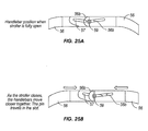
FIG. 25A is a partial enlarged view of a handle bar linkage for interconnecting lateral handle bar components in the stroller ofFIG. 1 , with the handle bar linkage shown in its fully open position; and -
FIG. 25B is a partial enlarged view of the handle bar linkage ofFIG. 25A , shown in a partially closed position. - The following description is provided to enable those skilled in the art to make and use the described embodiments set forth in the best modes contemplated for carrying out the invention. Various modifications, equivalents, variations, and alternatives, however, will remain readily apparent to those skilled in the art.
- A stroller embodying various aspects of the present invention is shown in
FIGS. 1 through 16 . It will be readily apparent to those skilled in the art, however, that the stroller ofFIGS. 1 through 16 represents but one of a wide variety of structures, configurations and modes of operation of strollers which fall within the scope of the present invention. - With reference to
FIGS. 1-4 astroller 10 is illustrated which comprises a pair offront wheels 12 having a frontwheel support structure 14 for supporting thefront wheels 12. The frontwheel support structure 14 is slidably engaged with aguide rail 16 for sliding movement of the thefront collar portion 26 of the frontwheel support structure 14 along the longitudinal axis 18 (seeFIGS. 11-13 ) of theguide rail 16. The frontwheel support structure 14 hasmembers FIGS. 1-4 ) and a collapsed position (seeFIGS. 7-10 ) upon movement of thefront collar 26 of the frontwheel support structure 14 along thelongitudinal axis 18 of theguide rail 16. - More specifically, the illustrated front
wheel support structure 14 comprises a pair of generally U-shapedwheel receiving members 20 for receivingrespective wheels 12, andaxles 20a to allow thewheels 12 to roll about theirrespective axles 20a. The frontwheel receiving members 20 are pivotally connected to a first end 22a offront wheel connector 22 to allow thewheels 12 to pivot about respective axes substantially parallel to theiraxes 20a to accommodate changes in the rolling direction of the front of the stroller. Thesecond end 22b of thefront wheel connector 22 is pivotally connected to thefront collar 26.Struts 24 are pivotally connected at afirst end 24a to thefront wheel connector 22, and thestruts 24 are pivotally connected at asecond end 24b to thefront abutment plate 29. - Accordingly, the
front wheel connector 22,strut 24 andfront collar 26 form a linkage whereby thefront wheels 12 and their associated frontwheel support structure 14 are movable between their collapsed positions (FIGS. 7-10 ) and their open positions (FIGS 1-4 ) upon movement of thefront collar 26 along thelongitudinal axis 18 of theguide rail 16. Afront abutment plate 29 is fixedly connected to thefront end 16a of theguide rail 16 and receives thefront wheel connectors 22 when the frontwheel support structure 14 is in its fully open position, such that when thestroller 10 is in its fully open position thefront wheel members 22 are secured between thefront abutment member 29 and the front wheelconnector securing portion 28 of thefront collar 26 as shown inFIG. 1 . A pair ofseat support arms 94 are provided to support a seat (not shown). - With continued reference to
FIGS. 1-4 thestroller 10 further comprises a pair ofrear wheels 30 having a rearwheel support structure 32 for supporting therear wheels 30. The rearwheel support structure 32 is slidably engaged with theguide rail 16 for sliding movement of therear collar portion 34 of the rearwheel support structure 32 along thelongitudinal axis 18 of theguide rail 16. The rearwheel support structure 32 hasmembers FIGS. 1-4 ) and a collapsed position (seeFIGS. 7-10 ) upon movement of therear collar 34 of the rearwheel support structure 32 along thelongitudinal axis 18 of theguide rail 16. - More specifically, the rear
wheel support structure 32 ofstroller 10 comprises a rearaxle supporting member 36 at each of therear wheels 30 for supporting therespective axles 31 of therear wheels 30 to allow therear wheels 30 to roll about theirrespective axles 31. The rearaxle support members 36 preferably each have a braking mechanism of the type well known in the art for selectively locking the rear wheels to prevent inadvertent rolling movement of the stroller when the braking mechanism is locked. The rearaxle support members 36 are fixedly connected to therear ends 40a of therear legs 40, with the front ends 40b of therear legs 40 pivotally connected to thecentral collar 42 which is attached in a fixed position to theguide rail 16. The guide rail may be configured to define a suitable mounting position for thecentral collar 42, and to maintain thecentral collar 42 at a suitable longitudinal position along theguide rail 16. The rear ends 40a of therear legs 40 are pivotally connected to the lower ends 38a of therear wheel connectors 38 throughbrackets 44, with the upper ends 38b of therear wheel connectors 38 pivotally connected to the rearmember securing portion 46 of therear collar 34. Accordingly, therear wheel connector 38,rear leg 40 andrear collar 34 form a linkage whereby therear wheels 30 and their associated rearwheel support structure 32 are movable between their collapsed positions (FIGS. 7-10 ) and their open positions (FIGS 1-4 ) upon movement of therear collar 34 along thelongitudinal axis 18 of theguide rail 16. - The rear
member securing portion 46 of therear collar 34 has a pair of recesses for receiving the upper ends 38b of therear wheel connectors 38, and arear abutment member 48 is fixedly connected to therear end 16b of theguide rail 16 such that when thestroller 10 is in its fully open position the upper ends 38b of therear wheel connectors 38 are secured between therear abutment member 48 and the rearmember securing portion 46 of therear collar 34. - A generally U-shaped frame member comprised of two separate
lateral frame components 50 is pivotally connected to thefront end 16a of theguide rail 16 through aframe mounting portion 52 of thefront abutment member 29, to allow each of thelateral frame components 50 to pivot or rotate relative to thefront abutment member 29. A pair of arcuateframe supporting members 54 each have alower end 54b pivotally connected to the rearmember securing portion 46 of therear collar 34 and anupper end 54a pivotally connected to a respectiveupper end 50a of the twolateral frame members 50. The rearmember securing portion 46 of therear collar 34 has a pair of recesses for receiving the respective lower ends 54b of theframe supporting members 54 when therear collar 34 is in its fully open position. Hence, when therear collar 34 is in its fully open position the lower ends 54b of theframe supporting members 54 are secured between the rearmember securing portion 46 of therear collar 34 and therear abutment member 48. - As best seen in
FIGS. 1 ,10 ,25A and 25B , a generally U-shaped handle bar is provided comprised of two lateralhandle bar components 56 having lower ends 56a pivotally connected to respective upper ends 50a of the frame member. Adjacent theupper end 56b of one of the lateralhandle bar components 56 anelongated slot 57 is provided, and adjacent theupper end 56b of the other lateralhandle bar component 56 asuitable pin 59 is provided which is slidably received and retained within theslot 57 of the other lateralhandle bar component 56. This slidable linkage allows the upper ends 56b of the lateralhandle bar components 56 to move toward and away from one another (as seen in comparingFIGS. 25A and 25B ) as the lateralhandle bar components 56 pivot between their collapsed and open positions. This allows the overall width of the generally U-shaped handle bar to decrease (consistent with the decrease in the lateral width of the wheels) as the lateralhandle bar components 56 move from their open position as shown inFIG. 1 to their collapsed positions shown inFIG. 10 wherein a portion of the upper ends 56b of the lateralhandle bar components 56 overlap one another to provide a compact configuration. As best seen inFIGS. 25A and 25B , the handle bars have an inclined portion adjacent their ends at the area in which the upper end portions of the handle bar members overlap to facilitate sliding and overlapping movement of the end portions without requiring pivotal movement of either of the lateral handle bar members. Accordingly, the two lateralhandle bar components 56 act as a single generally U-shaped handlebar when the two lateralhandle bar components 56 are in their open positions as inFIG. 1 at which they function as a single handle bar unit due to the pin-in-slot linkage maintaining the upper ends 56b of the two lateralhandle bar components 56 connected together. - In accordance with an aspect of the invention, two lateral handle bar components which are not permanently interconnected at their upper ends may be utilized. It may be desirable to provide a handle bar latch mechanism (not shown) which engages the upper ends 56b of the two lateral
handle bar components 56 to retain them interconnected when thehandle bar components 56 are in their open position, but which allows release of the two lateralhandle bar components 56 to allow them to move independently of one another when not in their open position. The release of the handle bar latch mechanism may be automated so that the latch mechanism releases or unlatches upon actuation of a control switch or a controller. The stroller may be constructed such that release of the handle bar latch mechanism, either manually or automatically, may actuate automatic movement of one or more additional stroller components as suitable. - With reference now to
FIGS. 1 and14-16 , each of the two lateralhandle bar components 56 and theframe supporting members 54 are pivotally connected to the upper ends 50a of the frame member. More specifically, theframe supporting member 54 has aframe gear member 58 fixed thereto such that upon pivoting movement of theframe supporting members 54 relative to theframe member 50 aboutpivot pin 60 theframe gear member 58 pivots aboutpivot pin 60 in the same rotational direction. The ends 56a of thehandle bar 56 have handlebar gear members 62 fixed thereto and in engagement with theframe gear member 58 such that upon pivotal movement of theframe supporting members 54 relative to theframe member 50 thehandle bar components 56 are pivoted relative to theframe member 50. This defines a simultaneous folding and unfolding gear arrangement referred to generally at 51. - More specifically, upon movement of the
frame supporting members 54 from their fully opened position ofFIG. 14 to their partially open position ofFIG. 15 , theframe gear member 58 pivots aboutpivot pin 60 which rotates the handlebar gear member 62 which pivots both of thehandle bar components 56 forward from the open position ofFIG. 14 to the partially open position ofFIG. 15 . The gears and handle bar components are configured such that upon movement of theframe supporting members 54 to their fully collapsed positions relative to theframe members 50 as shown inFIG. 16 , thehandle bar components 56 are moved to their fully collapsed positions as shown inFIG. 16 . Similarly, upon movement of theframe supporting members 54 from their fully collapsed position ofFIG. 16 toward their fully open position ofFIG. 14 , thehandle bar components 56 are moved through the gear arrangement toward its fully open position as well. - Although the illustrated and described
gear arrangement 51 may be used to achieve the desired movement of thehandle bar 56 to its fully collapsed position upon movement of theframe supporting members 54 to their fully collapsed position, and to achieve the desired movement of thehandle bar 56 to its fully open position upon movement of theframe supporting members 54 to their fully open position, a variety of other arrangements may be used in addition to, or instead of, gears for achieving this, such as mechanical linkages, a drive mechanism in operative engagement with the handle bars, cable connections, pneumatics, and others. The handlebar gear member 62 resides within agear housing 64, andframe gear member 58 resides within framegear member enclosure 66 which also accommodates a portion of the gear housing therein, so theframe gear member 58 and handlebar gear member 62 are covered at all times throughout collapsing, opening and use of the stroller. - With reference to
FIG. 14A , the above describedgear arrangement 51 can be modified to provide a latching mechanism suitable for use in connection with inventive aspects of strollers of the present invention. Alatch member 67 is provided at theend 56b of the lateralhandle bar component 56 which is spring biased to its extended position extending outwardly from theend 56b, as shown inFIG. 14A . Thelatch member 67 is movable to a retracted position not extending outwardly from theend 56b. Arecess 69 for receiving thelatch member 67 when it is in its extended position is provided in thegear housing 64 to receive and engage thelatch member 67 therein, and thereby engage thehandle bar member 56. Due to the single degree of freedom of the stroller linkage, this prevents the stroller from being moved toward its collapsed or folded position. Thelatch member 67 can be released from therecess 69 by moving the latch to its retracted position to disengage thelatch member 67 and thereby disengage thehandle bar member 56 to allow rotational movement of the handle bar member and accordingly allow movement of the stroller toward its collapsed position. Anarcuate slot 71 is provided in thegear housing 64 which slidably receives and retains a pin or rivet 73 on theframe member 50 to limit the extent of pivotal movement of theframe member 50 relative to thehandle bar component 56 to provide alignment of therecess 69 with thelatch member 67 to assure the latch member is properly received and engaged in therecess 69 when the stroller is in its open position and thelatch member 67 is spring biased into therecess 69. Theend 56b is arcuate to correspond to the arcuate or circular perimeter of thegear housing 64, whereby after the latch has been disengaged and the stroller has been moved to its collapsed position, upon movement of the stroller toward its open position thelatch member 67 is spring biased against the arcuate perimeter of thegear housing 64 until the stroller is fully open, at which point thelatch member 67 is aligned with, and spring biased into, therecess 69 to prevent movement of the stroller toward its collapsed position until thelatch member 67 is retracted. - With reference now to
FIGS. 11-13 , thestroller 10 has adrive mechanism 70 through which thestroller 10 may be moved back and forth between its open and collapsed positions. A rear threadedmember 72 is mounted in theguide rail 16 for rotation within the guide rail interior about the longitudinal axis of the rear threaded member, with the longitudinal axis of the rear threaded member being coaxial with thelongitudinal axis 18 of the guide rail. The rear threadedmember 72 is supported bybearings member pulley 76 is fixedly connected to the rear threadedmember 72. It is preferred that the threadedmember pulley 76 is mounted in close proximity to thebearing 74b, so that lateral forces exerted on the threadedmember pulley 76 are taken upon by the bearing 74b such that separate bearings are not required for the front threadedmember 86 which is discussed below. Amotor 78 is mounted in a fixed position on the guide rail and has adrive pulley 80 connected to its shaft and a belt (not shown) extends between thedrive pulley 80 and threadedmember pulley 76 through which the threadedmember pulley 76 is rotated about its longitudinal axis upon actuation of themotor 78. Arear nut member 82 is in threaded engagement with the rear threadedmember 72, with therear nut member 82 having a mountingportion 82a which extends outwardly of theguide rail 16 through thelongitudinally extending slot 84 in theguide rail 16. - Accordingly, as the
motor 78 is actuated, themotor 78 effects rotation of the rear threadedmember 72 through the belt and pulleys (with the lateral forces exerted on the threadedmember pulley 76 by the belt being taken up by thebearings member 72 due to the mountingportion 82a of therear nut member 82 extending outwardly of theslot 84 and bearing against the sides of the slot when the rear threadedmember 72 rotates) is driven longitudinally along the rear threadedmember 72. Therear collar 34 is mounted to the mountingportion 82a of therear nut member 82 such that therear collar 34 and the rearmember securing portion 46 connected thereto moves longitudinally along theguide rail 16 together with therear nut member 82 as the rear threadedmember 72 is rotated by themotor 78. With the rearwheel support structure 32 engaged with therear collar 34, the longitudinal movement of therear collar 72 along theguide rail 16 thereby effects movement of the rearwheel support structure 32 between its collapsed and open positions, with therear collar 34 moving in a first longitudinal direction along theguide rail 16 upon rotation of the rear threadedmember 72 in first rotational direction, and therear collar 34 moving in a second longitudinal direction along theguide rail 16 upon rotation of the rear threadedmember 72 in an opposition, second rotational direction to move the rear wheel support structure between its collapsed and open positions. Hence, thedrive mechanism 70 is operatively engaged with the rearwheel support structure 32 to move therear wheels 30 between their collapsed and open positions. - With continued reference to
FIGS. 11-13 , a front threadedmember 86 is mounted in theguide rail 16 for rotation within the guide rail interior about the longitudinal axis of the front threaded member, with the longitudinal axis of the front threaded member being coaxial with thelongitudinal axis 18 of theguide rail 16 in a manner similar to the rear threadedmember 72. Therear end 86a of the front threadedmember 86 is coupled to the rear threadedmember 72 throughcoupling member 88 such that the front threadedmember 86 and the rear threadedmember 72 rotate together. Thefront end 86b of the front threadedmember 86 is supported in a suitable recess in the rear side of the front abutment member which allows rotation of the front threadedmember 86 about its longitudinal axis, which is coaxial with the longitudinal axis of the rear threadedmember 72. - A
front nut member 90 is in threaded engagement with the front threadedmember 86, with thefront nut member 82 having a mountingportion 90a which extends outwardly of theguide rail 16 through thelongitudinally extending slot 84 in theguide rail 16. Accordingly, as themotor 78 is actuated, themotor 78 effects rotation of the front threaded member 86 (simultaneously and in the same rotational direction as the rear threaded member 72) whereby the front nut member 90 (which is prevented from rotating together with the front threadedmember 86 due to the mountingportion 90a of thefront nut member 82 extending outwardly of theslot 84 and bearing against the sides of the slot when the front threadedmember 86 rotates) is driven longitudinally along the front threadedmember 86. Thefront collar 26 is mounted to the mountingportion 90a of thefront nut member 90 such that thefront collar 90 and the front wheelconnector securing portion 28 connected thereto moves longitudinally along theguide rail 16 together with thefront nut member 90 as the front threadedmember 86 is rotated by themotor 78. With the frontwheel support structure 14 engaged with thefront collar 26, the longitudinal movement of thefront collar 26 along theguide rail 16 thereby effects movement of the frontwheel support structure 14 between its collapsed and open positions, with thefront collar 26 moving in a first longitudinal direction along theguide rail 16 upon rotation of the front threadedmember 86 in first rotational direction, and thefront collar 90 moving in a second longitudinal direction along theguide rail 16 upon rotation of the front threadedmember 86 in an opposition, second rotational direction to move the frontwheel support structure 14 between its collapsed and open positions. Hence, thedrive mechanism 70 is operatively engaged with the frontwheel support structure 14 to move thefront wheels 12 between their collapsed and open positions. - As mentioned above, the front and rear threaded
members members rear collars wheel support structures rear collars wheel support structures wheel support structures stroller 10, the threads of the front and rear threadedmembers members rear collar 34 is displaced a greater distance along thelongitudinal axis 18 of theguide rail 16 than thefront collar 26 is displaced along thelongitudinal axis 18 of the guide rail 16 (with the simultaneous displacement of the front andrear collars - Accordingly, it will be appreciated that with the coupled front and rear threaded members being considered part of the frame, the
stroller 10 provides a frame, a front wheel support structure, and a rear wheel support structure which define a linkage having a single degree of freedom, such that movement of any one of the coupled threaded members, front wheel support structure, or rearwheel support structure 34 relative to one another toward their collapsed or open positions may effect movement of the others toward their collapsed or open positions. By accurately controlling and/or preventing rotation of the coupled front and rear threaded members, the movement and/or securing in place of the front and rear wheel support structures may be achieved. Further, with the handle bars 56 operatively coupled to theframe supporting members 54 of the rear wheel assembly by the gear arrangement discussed above, the coupled threaded members, front wheel support structure, rear wheel support structure and handle bars form a linkage having a single degree of freedom, whereby by accurately controlling and/or preventing rotation of the coupled front and rear threaded members, the movement and/or securing in place of the handle bars, and the front and rear wheel support structures may be achieved. - A
control switch 92 is provided, preferably in thehandle bar 56 for ease of access, for effecting actuation of thedrive mechanism 70. Thecontrol switch 92 is operatively connected to the motor 78 (which may be through a controller, such as a microprocessor, not shown) to control actuation of themotor 78, which in turn controls thedrive mechanism 70, which in turn controls movement of the front and rearwheel support members control switch 92 andmotor 78 are all disposed internally of the stroller elements, such as extending internally within hollow tubular members. Thecontrol switch 92, or a separate control switch and/or a common controller, may also be operatively coupled to one or more latch mechanisms to move the latch mechanisms from their latched positions in which they prevent the stroller from moving from its fully open position toward its collapsed position, to their unlatched positions in which they allow the stroller to move from its fully open position towards its collapsed position. Themotor 78, or a separate drive, may be operatively connected to a control switch and/or controller to effect automatic movement of the latches upon actuation by thecontrol switch 94. The unlatching of the one or more latches is preferably carried out prior to, or simultaneous with the initiation actuation of themotor 78 anddrive mechanism 70 of which the motor may be a part. - In accordance with an aspect of the invention, a control switch may be provided at or in proximity with one or more latches on the stroller (or operatively engaged with one or more latches), such that upon, or subsequent to, manually unlatching the one or more latches the actuator is actuated to effect automatic movement of the desired one or more stroller components from a first position to a second position. That is, a control switch such as a position sensing switch (which may be an optical switch, electrical contact switch, or any other type of switch) may be provided which is operatively engaged with a controller which controls the actuation of the drive mechanism as desired (which may be in any of a wide variety of rates, sequences, options, etc.) The control switch or switches may be located and configured to be triggered or actuated during conventional manual unlatching of the latch or latches, or may be at a convenient location on the stroller which allows the control switch to be easily actuated while, or immediately subsequent to, unlatching of the latch or latches. It may be desirable to provide an arrangement in which two or more control switches associated with respective latches are required to both be actuated to effect automatic movement of the desired one or more stroller components from a first position to a second position.
- A single control switch may actuate a single controller, such as a microprocessor, which in turn actuates two or more separate drive mechanisms. Alternatively, a single control switch may actuate two or more controllers which each in turn actuate one or more separate drive mechanisms.
- The
stroller 10 may also have adisplay 96, such as on thehandle bar 56, to provide information to the user as to any of a wide variety of information such as confirmation that the front and rear wheel support structures are secured in their fully open positions, that latches are locked, that a brake is engaged, ambient temperature, distance traveled, time, or the like. - With reference now to
FIGS. 17-20 , astroller 100 embodying various aspects of the present invention is illustrated. Thestroller 100 is movable or foldable between a collapsed position (seeFIG. 20 ) and an open or operative position (seeFIGS. 17 and18 ). An intermediate stroller position between collapsed and open is illustrated inFIG. 19 . - The
stroller 100 has a frontwheel support structure 104 having a pair of laterally spacedfront support legs 110 withfront wheels 108 rotatably mounted thereon. Thestroller 100 also has a rearwheel support structure 106 having a pair of laterally spacedrear support legs 112 withrear wheels 114 rotatably mounted thereon. The upper ends of the respectivefront support legs 100 andrear support legs 112 are pivotally connected to one another which allows the front andrear wheels - As best seen in
FIGS. 17 and19 , thestroller 100 also has ahandlebar 116 with a pair of laterally spacedlegs 118, whichlegs 118 are pivotally connected at theirends 118a to respective sides of therear end 120a of aseat member 120 to allow pivotal movement between theseat member 120 andhandlebar legs 118. Theseat member 120 is also pivotally connected near itsfront end 120b to thefront support legs 110 to allow pivotal movement between theseat member 120 and thefront support legs 110. Thestroller 100 has a pair of arms 122 (seeFIG. 17 ) which are each pivotally connected at one of their ends to thehandlebar legs 116 and pivotally connected to therear support legs 112. A link 123 is provided extending between and pivotally connected to thelower end 118a of the handlebar and therear support leg 112. Accordingly, thefront support legs 110,rear support legs 112,seat member 120,arms 122, links 123 andhandlebar 116 defme a linkage having a single degree of freedom, such that each of these components move simultaneously between their collapsed and open position, and such that prevention of motion of various components relative to each other prevents movement of the stroller between its collapsed and open positions. The link 123 facilitates the linkage mechanism of thestroller 100 as having a single degree of freedom, with left and right sides coupled together by cross braces. A locking mechanism or latch may be provided which, when moved to its locking or latched position, allows locking of thestroller 100 in its open position during use. - In accordance with an aspect of the invention, a drive motor or
mechanism 124 is operatively coupled to both theseat member 120 andfront support legs 110 at their pivot axis such that, when actuated, themotor 124 pivots theseat member 120 relative to the front support legs 110 (as seen in comparingFIGS. 18 through 20 ). Because the linkage mechanism of thestroller 100 has a single degree of freedom, the pivoting of theseat 120 relative to thefront support legs 110 by themotor 124 effects movement of each of thefront support legs 110,rear support legs 112,seat member 120,arms 122 andhandlebar 116 between their open and collapsed positions. The illustratedstroller 100 has themotor 124 placed at the pivot axis between theseat 120 andfront support member 110 with the shaft of themotor 124 coaxial with the pivot axis between theseat 120 andfront support legs 110 in a direct drive system, with themotor 124 mounted to thefront support leg 110 and the motor shaft connected to theseat member 120. However, it may desirable to have themotor 124 mounted at a different location on thestroller 100 such as under theseat 120 using an indirect drive system in which the motor is not located at the pivot axis, but is mounted to thefront support member 110 and the motor shaft is operatively connected to theseat member 120. - Although the illustrated
stroller 100 has the motor controlling pivoting movement of thefront support leg 110 relative to theseat member 120, one or more motors may be placed at any one or more pivot axes of the linkage to pivot any two pivotally connected members of the single degree of freedom linkage, whereby due to the single degree of freedom of the linkage the one or more motors may control movement of the stroller between its open and collapsed positions. Also, in accordance with a further aspect of the invention, one or more motors or other drives may be provided a suitable location away from the stroller component or components which are desired to be moved, with a suitable operative connection extending between the one or more drives and the stroller component or components to be moved by the drive. Also, in accordance with another aspect of the present invention, a stroller may be provided in which separate drive mechanisms move different components of the stroller which are not interconnected as a single degree of freedom linkage, or one drive mechanism may drive and effect movement of a plurality of different components of the stroller which are not interconnected, or one drive mechanism may drive a plurality of different components of the stroller which are interconnected as a single degree of freedom linkage with another drive mechanism driving one or more additional components of the stroller. - In accordance with another aspect of the invention, a stroller may be provided in which a drive mechanism is operatively connected with any one or more stroller components to move the one or more stroller components between any first desired position and any second desired position. Such stroller components may be wheel support structures, handlebars, cup holders, canopies, or any other stroller component for which it is desired to easily and automatically move from a first position to a second position. Such movement may be to achieve compactness in a first position and operational use in a second position, but the invention is not limited to this and there is a virtually limitless number of potential advantageous stroller embodiments in which it may be desirable to facilitate easy movement of one or more stroller components between first position and one or more other positions.
- A stroller may be provided in which a drive mechanism is operatively connected with one or more components which are not related to moving the front or rear wheels, or left and right wheels, between open and collapsed positions. As an example, additional stroller components such as visors, cup holders, etc. may have a drive mechanism operatively connected therewith to move them between a first desired position and one or more other desired positions, which movement may be carried out in conjunction with the opening and collapsing movement of the stroller and/or independently. Accordingly, by merely actuating a readily accessible control switch which is operatively connected to a drive mechanism of the stroller (which operative connection may be direct or through a controller), one or more stroller components operatively connected to the drive mechanism (which operative connection may be direct or indirect) may be easily moved from a first desired position to a second desired position.
- With reference to
FIGS. 21-23 , thestroller 100 may be provided with one or more latches or locking mechanisms (such as inFIG. 21 or any other latches or locking mechanisms) which are moveable between a latched or locked position in which the stroller is prevented from moving out of its open position, and an unlatched or unlocked position in which the stroller is allowed to move freely out of its open position toward its collapsed position. With reference toFIGS. 22 and23 , the latches can be controlled by a smalllatch release motor 125 disposed in thehandlebar 116, a cup holder or the like extending across the handlebar, or another suitable location on thestroller 100, with the shaft of thelatch release motor 125 operatively engaged withlatch release cables 126 which extend to the latch or locking release mechanisms on either side of the stroller. Upon actuation of the latch release motor, thelatch release cables 126 are pulled to release the latch or latches. Separate or, preferably linked,cables 126a also extend to thehandlebar 116 to a manual latch cable pulling mechanism (not shown) to allow manual unlatching of the latches, particularly in the event of failure or obstruction of thelatch release motor 125. The latch release cables preferably also extend and reside with the components of the stroller and are not exposed or visible. - In accordance with another aspect of the invention, the stroller may be designed so that the releasing of the latches is synchronized with the movement of one or more other components of the stroller to their collapsed positions. This may be done through mechanical linkages or the like, through a suitable controller, both, or in other ways.
- A resistance sensing device and/or timer may be operatively connected to the controller to stop movement and/or move toward the unfolded or open position when folding is interrupted, e.g. when too much resistance toward folding movement is encountered or when fully closed position is not achieved within a predetermined time. Alternatively, or additionally, a clutch may be provided between the motor and the elements to which it is connected to provide slippage of the driving force of the motor if too much resistance is encountered.
- In accordance with another aspect of the invention, a manual override may be provided to allow manual movement of the stroller between its open and closed positions and/or manual movement of any stroller components between their first and second positions which would normally be carried out automatically by a drive mechanism. Such manual override may be desirable for any of a number of reasons, such as the power source being too low to effect the desired automatic movement or the failure of any parts.
A wide variety of manual override mechanism may be utilized in connection with the present invention. For instance, a clutch or clutches may be provided between one or more drive mechanism elements and their associated stroller components for use as a manual override, whereby the clutch may be moved to a position in which it effects disengagement of the drive mechanism. As another example, a mechanical lever or rotary element may be provided at any point in the drive mechanism and/or between the drive mechanism and one or more stroller components associated with the drive mechanism, which is movable between an automatic position (in which a drive mechanism is operatively engaged with one or more stroller components to move the one or more stroller components automatically) and a manual position (in which a drive mechanism is disengaged from its operative engagement with one or more stroller components). For instance, with reference to thedrive mechanism 70 of the stroller 10 a disengaging mechanism, such as a rotary disengaging element, may be provided which is movable from an automatic position in which the disengaging mechanism allows and/or maintains the operative engagement between the mountingportion 82a of rear nut member 82 (which extends outwardly of theguide rail 16 through thelongitudinally extending slot 84 in the guide rail 16) and therear collar 34 which is mounted to the mountingportion 82a of therear nut member 82 such that therear collar 34 and the rearmember securing portion 46 connected thereto moves longitudinally along theguide rail 16 together with therear nut member 82 as the rear threadedmember 72 is rotated - and a manual position in which the disengaging mechanism disengages the mountingportion 82a of rear nut member 82 (which extends outwardly of theguide rail 16 through thelongitudinally extending slot 84 in the guide rail 16) from the mountingportion 82a of therear nut member 82 such that therear collar 34 and the rearmember securing portion 46 connected thereto may be moved manually, longitudinally along theguide rail 16 disengaged from the threaded member. Accordingly, when the disengaging mechanism is moved to its manual position, the rear collar may slide freely along theguide rail 16 by manual movement. The same, similar, or other disengaging mechanism may be provided for the front collar to allow the front collar to slide freely along the guide rail when its associated disengaging mechanism is moved to its manual position. - When in its manual position, the disengaging mechanism may engage one or more locking mechanisms when the stroller is moved to its open position and/or closed position to retain the stroller in its open position and/or closed position, such as to prevent the collars from sliding away from their open positions during use and/or away from their closed positions during transport or storage, with the disengaging mechanism being configured such that it does not engage the locking mechanism(s) when in its automatic position (in which the drive mechanism may prevent movement of the stroller away from its open position during use and/or prevent movement of the stroller toward its open position during transport or storage. The locking mechanism(s) may be manually released.
- It will be appreciated that the above is merely by way of example, and that a wide variety of disengaging mechanisms may be utilized with a wide variety of different stroller designs, without departing from the inventive concepts of the present invention.
- The movement or movements of the inventive strollers of the present invention can be carried out in a wide variety of ways, such as telescoping of components, sliding of components, pivoting of components, rectilinear movement of components, cam driven or guided movement of components, or any other known linkage which allows movement of two or more components relative to one another.
- In accordance with one aspect of the present invention, virtually any stroller construction which has one or more front wheels and one or more rear wheels, or having any other wheel configuration such as a circular arrangement of the wheels, left and right wheels, or any other arrangement, in which the stroller has some type of drive for moving at least one of the wheels from a first position to a second position may be constructed. In accordance with another aspect of the invention, virtually any stroller construction can be utilized which allows automatic movement of at least one its wheels from an open position to a collapsed position, or back and forth between collapsed and open positions, or between an extended position and a retracted position. In accordance with another aspect of the invention, a stroller may be provided having a frame with one or more components, which may be wheel components and/or other stroller components or attachments (or components to which attachments may be connected) with a drive operatively connected with the one or more components to move them from a first position to a second position. This may be used for automatic movement of the components between any desired first and second positions. In accordance with another aspect of the invention, one or more stroller components or attachments may be moved between three or more selective positions by the drive mechanism and/or control switches, and or one or more controllers.
- In accordance with an aspect of the invention, a controller may be used to control the drive. The controller may actuate the drive mechanism(s) for a predetermined period of time to move the stroller between its fully open and fully collapsed positions, and/or sensor(s) may be used to limit the actuation of the drive mechanism(s) when the component(s) reach and/or approach their fully open and/or fully collapsed positions. The controller and drive may be constructed to allow the drive to move or operate at different speeds or rate of movement over different portions of its movement, which (depending on the stroller construction and operative engagement of the drive with the stroller components) may allow the stroller components to be moved at a constant or approximately constant speed, or may allow the stroller components to be moved at different speeds over different portions of their movement. By way of example, it may be desirable to have one or more stroller components move quickly during their initial movement(s) and more slowly during their final movement(s), or vice-versa.
- In accordance with another aspect of the present invention, a stroller may be provided having latch or locking components operatively connected with the drive mechanism, or a separate drive mechanism, which latches are moveable between a locking position which maintains the stroller in its collapsed position and an unlocked position which allows the stroller to move from its collapsed position to it open position.
- Backup mechanical systems may be provided to serve as the drive for moving the wheels and/or other stroller components. A mechanical system(s) may use elements common with the automatic system(s), use independent element(s), or both.
- As used herein, movement of the stroller between its collapsed and open positions refers to movement of one or more of the stroller components between their collapsed and open positions, and vice-versa.
- As used herein, the terms drive and drive mechanism may refer simply to a motor or may refer to a more complex drive system which may be a motor and other components or any other device capable of moving itself and/or other elements. However, the invention is not limited to drives or drive mechanisms having a motor. For instance, but not by way of limitation, the drive or drive mechanism may be a hydraulic or pneumatic drive, with hydraulic or pneumatic tubes extending from a hydraulic or pneumatic pump, internally and/or externally of one or more stroller components, to desired locations of the stroller to effect movement of one or more stroller components. Cables, running internally and/or externally of one or more stroller components, may be utilized. Suitable accommodation for the cables, pneumatic tubing, hydraulic tubing and/or electrical wires is preferably provided to prevent pinching, folding or other deformation which would prevent suitable or optimal operation of these elements. An energy storing drive or drive mechanism (such as one utilizing a spring loaded element, other resilient element or electromagnetic storage element, which stores energy when one or more stroller components are moved from one position to another for subsequent release of part or all of the stored energy to effect movement of the same or other stroller components, may be utilized. Rotary drives and/or drive mechanisms, or non-rotary drives and/or drive mechanisms may be utilized. One type of drive or drive mechanism may be utilized, or any combination of two or more drive mechanisms may be utilized either in combination with one another or individually.
- In accordance with an aspect of the invention, the drive or drive mechanism may be located at, or in proximity with, a location (or locations) on the stroller at which one or more stroller components are desired to be moved, or the drive or drive mechanism(s) may be located remote from such location or locations, with suitable operative engagement extending between a remotely located drive or drive mechanism and the location or locations on the stroller at which one or more stroller components are desired to be moved. Such operative engagement may include for instance cables, hydraulic tubes, pneumatic tubes, electromagnetic forces, electric wires, or any of a wide variety of other engagements.
- In accordance with another aspect of the present invention, the controller used to control the motor to control the collapsing and opening movements, or other desired stroller component movements, of the strollers of the present invention may be constructed and configured to have two or more discrete switches (not shown) which need to be actuated simultaneously, or in a predetermined sequence or pattern, to effect actuation of the motor and thereby the movable components of the stroller, so as to prevent inadvertent movement of the stroller components, such as inadvertent movement of a stroller toward its deployed and/or collapsed positions. The two or more discrete switches are preferably spaced sufficiently apart from one another, or otherwise disposed relative to one another, so as to prevent inadvertent actuation of one switch upon actuation of the other switch.
- The control switch or switches may be constructed to require that one switch, or a combination of switches, be engaged throughout the movement of the desired stroller components, such as during opening and/or folding operations of strollers designed for automatic opening and closing. Alternatively, a suitable control switch or switches, and/or suitable controller, may be provided such that only one actuation of a switch or switches is required to effect the desired movement of two or more stroller components, such as full movement of a stroller between its fully-deployed or open and/or fully-collapsed or folded positions. As a further alternative, a controller may be provided to move the stroller to a position intermediate its fully open and/or fully collapsed position, such as a midway condition, with one actuation of a switch or switches, and further or complete movement of the stroller to its fully deployed and/or fully collapsed positions requiring a subsequent actuation of a switch or switches.
- The controller may be constructed to automatically switch directions with each successive actuation. For example, should the movement of the stroller toward the fully-collapsed position be stopped at an intermediate point, such as upon a user noticing a toy in the stroller which is to be removed, but which has been enclosed by the partially-collapsed stroller, the user need only release the switch or switches and reengage them for movement in the opposite direction, toward the fully open position. The motor may then be stopped and re-actuated for movement of the stroller to its fully collapsed position.
- The control switch and/or controller may be mounted on the frame of the stroller, such as on the rear wheel support member or elsewhere on the stroller, or alternatively, the control switch and/or controller may be separate from the stroller, such as on a key fob or other portable device, and operated using wireless technology. This may facilitate the ability of a user to hold a child or baby with both hands throughout the opening and/or collapsing of the stroller.
- The controller may be configured and constructed utilizing any of a wide variety of known controller designs and/or mechanisms. For instance, the controller may utilize electrical contact switches and/or may utilize a processor, microprocessor or microcontroller.
- The controller may operate in conjunction with one or more sensors, such that upon actuation, or lack of actuation, of one or more sensors the motor does not operate even when the one or more switches, or other control actuation mechanism, which would normally actuate the motor, are properly actuated.
- The controller may also be provided with switches or other actuators for controlling additional items such as a timer, an alarm clock feature, a music device, a monitor, or any other desirable items. If desired, a general auxiliary device connector may be provided through which various auxiliary devices may be interchangeably connected and controlled by the controller and/or suitable control switch, which devices may be powered by the power source for the stroller, or through an independent power source.
- In accordance with another aspect of the invention, the movement of one or more front wheel support structures, one or more rear wheel support structures, and one or more latches may be carried out in a predetermined sequence. This predetermined sequence may be that the one or more latches are moved to their unlatched positions prior to the movement of the other members such as the front and rear wheel support structures, or the predetermined sequence may be that the latches are moved to their unlatched positions simultaneous with the movement of one or more components of the stroller toward their open positions, or any other sequence suitable for the particular stroller design and result to be achieved. A latch may also be provided to move to its locked position to keep the stroller in its collapsed position, which may be part of the predetermined sequence or a separate operation.
- In accordance with another aspect of the invention, the power source for driving the motor may be a replaceable and/or rechargeable battery or batteries, conventional battery or batteries, and/or a direct electrical supply such as that available from an electrical outlet. The power source may be permanently attached to the stroller, or may be removable for charging, replacement, or the like. To keep the overall stroller relatively low in weight and/or to keep production costs down, or for other reasons, a relatively small power source may be utilized which has sufficient power to move the stroller back and forth between its deployed and collapsed positions, but which does not have sufficient additional power to regularly or routinely power additional accessories or onboard systems without draining its power undesirably quickly. Alternatively, a larger power source may be utilized which not only has sufficient power to move the stroller back and forth between its open and collapsed conditions, but also has additional capacity to drive one or more additional accessories and/or onboard systems, which accessories and/or onboard systems may be integral with the stroller or may be modular additions or connections to the stroller. In accordance with an aspect of the invention, the stroller may be constructed and configured to recharge, or maintain a predetermined power level of, its onboard power source through a generator which is driven by the turning of the stroller wheels.
- In accordance with another aspect of the invention, a display may be utilized in conjunction with the stroller, which display or a portion thereof may be mounted onboard the stroller or be remote, to provide visual and/or audio feedback to the user about any desired feature or parameter, such as the position of the stroller frame, the presence of an object in the stroller, whether the stroller will move toward its open or collapsed condition when next actuated, the presence of a baby or child in the stroller, instructions for use and operation of the stroller, emergency telephone numbers, environmental conditions in which the stroller is being used, or any other desired feature or parameter.
- In accordance with yet another aspect of the invention, one or more object sensors may be utilized in conjunction with the stroller, with the object sensor or sensors having the ability to detect the presence of objects within the interior portion of the stroller and to interrupt and/or prevent movement of the stroller in the direction toward its collapsed condition when the object sensor detects the presence of an object within the interior portion of the stroller. The object sensor or sensors may be of any known type, or any type later developed, such as a mechanical weight sensor, a proximity sensor, a motion sensor, a light beam sensor, or any other device having the ability to detect the presence of an object within the interior of the stroller. The sensor or sensors may be electronic and may send a signal which is electrically acted upon to prevent or interrupt power to the motor, and/or the sensors may be mechanical and actuate a physical lock or a brake to prevent further collapsing or the full collapsing movement of the stroller.
- Sensors may also be used to detect the presence of modular add-on devices connected to the stroller, such that movement of the stroller to its collapsed condition is prevented when a connected add-on is detected, thereby preventing potential damage to the add-on device.
- In accordance with still another aspect of the invention, position sensors may be utilized at selective locations on the frame to send a signal indicative of the positions of one or more components or elements of the stroller. The position sensors can be used for several purposes, such as sending a signal to a display to provide a visual and/or audio indication to the user as to the current position or of the deployment or the collapsing of the stroller and/or to provide an interrupting signal (or non-signal) if a position sensor or sensors are not engaged as they would be during proper deployment and/or collapsing of the stroller. Any one or more of several known types of sensors may be utilized, such as rotary encoders at any one or more frame component pivot points, and/or limit or contact switches which are engaged as selective elements of the stroller move to their proper positions, or improper positions, during deployment and/or collapsing of the stroller. By way of example, positions sensors may be mounted to the stroller at positions which provide indication that the stroller has moved to its fully deployed condition, its fully collapsed condition, or any condition in-between; and/or position sensors may be mounted at locations to detect the engagement or lack of engagement of latches. Position sensors may operate in conjunction with electronic timer controls such that a signal to effect stoppage of power to the motor is sent if the position sensor is not engaged within a predetermined time period.
- If a motor is used as the drive mechanism, the motor may be of a reversible type, or alternatively, a single-direction motor with mechanical reversing means.
- In accordance with another aspect of the present invention, a stroller may be provided in which the front and/or rear wheels move front to back and/or back to front and/or side to side and/or top to bottom and/or bottom to top. This may apply to other stroller components as well. For instance, a stroller may be provided in which the wheels of the stroller remain on the ground or otherwise relatively stationary, while other stroller components move forwardly and/or rearwardly and/or sideways and/or upwardly and/or downwardly between collapsed and open positions.
- The stroller embodiments described in detail above, are simple, robust, easy to use, and relatively inexpensive. The various structures of the apparatus may all be made of any suitable plastics or formed of metals.
- From the foregoing, it can be seen that there has been provided features for an improved stroller.
Claims (8)
- A stroller (100), comprising:a collapsible carriage frame (104, 106, 116) movable between a collapsed position and an open position;a drive mechanism (124) operatively engaged with the collapsible carriage frame to move the collapsible carriage frame from the collapsed position to the open position;a disengaging mechanism for disengaging the operative engagement between the drive mechanism and the collapsible carriage frame to facilitate manual movement of the collapsible carriage frame,characterised in that the stroller further comprises:one or more latches (67) in operative engagement therewith, which one or more latches are moveable between a latched position in which the one or more latches prevent movement of the collapsible carriage frame toward its collapsed position, and an unlatched position in which the one or more latches allow movement of the collapsible carriage frame toward its collapsed position, with the one or more latches being movable to their unlatched positions by one or more latch drive mechanisms (125) operatively connected thereto.
- The stroller in accordance with claim 1, wherein the collapsible carriage frame includes an interior portion.
- The stroller in accordance with claim 2, further comprising an object sensor configured to detect the presence of objects within the interior portion of the collapsible carriage frame and send a signal to prevent actuation of the drive mechanism if an object is detected in the interior portion of the collapsible carriage frame.
- The stroller in accordance with claim 3, wherein the object sensor sends a signal to a display to provide a visual indication to a user if an object is present in the interior portion.
- The stroller in accordance with claim 1, further comprising at least one position sensor provided at a selective location on the collapsible carriage frame to send a signal indicative of the positions of at least one of the collapsible carriage frame to the control system.
- The stroller in accordance with claim 5, wherein the at least one position sensor sends the signal to a display to provide at least one of a visual indication and an audio indication to a user as to a current position of the collapsible carriage frame.
- The stroller in accordance with claim 1, further comprising one or more latch position sensors which detect when the one or more latches are in their latched positions, with the one or more latch position sensors sending a signal to stop actuation of the one or more latch drive mechanisms upon receipt of the signal.
- The stroller in accordance with claim 1, further comprising a display (96) and one or more latch position sensors which detect when the one or more latches are in their latched positions, with the one or more latch position sensors sending a signal to the display when the one or more latches are in their latched positions, with the display providing visual confirmation to the user that the one or more latches are in their latched positions.
Applications Claiming Priority (11)
| Application Number | Priority Date | Filing Date | Title |
|---|---|---|---|
| US89060807P | 2007-02-19 | 2007-02-19 | |
| US89060707P | 2007-02-19 | 2007-02-19 | |
| US89059707P | 2007-02-19 | 2007-02-19 | |
| US89060107P | 2007-02-19 | 2007-02-19 | |
| US89062407P | 2007-02-19 | 2007-02-19 | |
| US89061807P | 2007-02-19 | 2007-02-19 | |
| US89061307P | 2007-02-19 | 2007-02-19 | |
| US89060507P | 2007-02-19 | 2007-02-19 | |
| US89061907P | 2007-02-19 | 2007-02-19 | |
| US89061607P | 2007-02-19 | 2007-02-19 | |
| EP08730032.3A EP2114747B1 (en) | 2007-02-19 | 2008-02-15 | Stroller |
Related Parent Applications (3)
| Application Number | Title | Priority Date | Filing Date |
|---|---|---|---|
| EP08730032.3A Division-Into EP2114747B1 (en) | 2007-02-19 | 2008-02-15 | Stroller |
| EP08730032.3A Division EP2114747B1 (en) | 2007-02-19 | 2008-02-15 | Stroller |
| EP08730032.3 Division | 2008-02-15 |
Publications (2)
| Publication Number | Publication Date |
|---|---|
| EP2565100A1 EP2565100A1 (en) | 2013-03-06 |
| EP2565100B1 true EP2565100B1 (en) | 2014-10-01 |
Family
ID=39710442
Family Applications (3)
| Application Number | Title | Priority Date | Filing Date |
|---|---|---|---|
| EP12177472.3A Not-in-force EP2570324B1 (en) | 2007-02-19 | 2008-02-15 | Stroller |
| EP12177476.4A Not-in-force EP2565100B1 (en) | 2007-02-19 | 2008-02-15 | Stroller |
| EP08730032.3A Not-in-force EP2114747B1 (en) | 2007-02-19 | 2008-02-15 | Stroller |
Family Applications Before (1)
| Application Number | Title | Priority Date | Filing Date |
|---|---|---|---|
| EP12177472.3A Not-in-force EP2570324B1 (en) | 2007-02-19 | 2008-02-15 | Stroller |
Family Applications After (1)
| Application Number | Title | Priority Date | Filing Date |
|---|---|---|---|
| EP08730032.3A Not-in-force EP2114747B1 (en) | 2007-02-19 | 2008-02-15 | Stroller |
Country Status (6)
| Country | Link |
|---|---|
| US (5) | US20080211206A1 (en) |
| EP (3) | EP2570324B1 (en) |
| CN (2) | CN102963411A (en) |
| AU (1) | AU2008218786B2 (en) |
| CA (1) | CA2678602C (en) |
| WO (1) | WO2008103616A1 (en) |
Families Citing this family (61)
| Publication number | Priority date | Publication date | Assignee | Title |
|---|---|---|---|---|
| WO2005108181A2 (en) | 2004-04-30 | 2005-11-17 | Dynamic Brands, Llc | Folding baby stroller |
| WO2008079423A1 (en) * | 2006-04-03 | 2008-07-03 | Graco Children's Products Inc. | Stroller seat recline mechanism |
| TWM301820U (en) * | 2006-04-25 | 2006-12-01 | Link Treasure Ltd | Framework structure of a baby carriage |
| EP1970286A1 (en) * | 2007-03-15 | 2008-09-17 | Team-Tex | Device for transporting a child |
| US7571926B2 (en) * | 2007-07-12 | 2009-08-11 | Ming-Tai Huang | Foldable toy stroller |
| EP2190395A1 (en) * | 2007-09-21 | 2010-06-02 | Daedalus Wings, Inc. | Modular wheelchair with in-line chassis |
| US20100090443A1 (en) * | 2008-10-09 | 2010-04-15 | Gordon Liao | Golf Bag Cart |
| US8720912B2 (en) | 2008-10-09 | 2014-05-13 | Unique Product & Design Co., Ltd. | Golf bag cart |
| CN101844574B (en) * | 2009-03-23 | 2013-02-13 | 明门香港股份有限公司 | Stroller |
| US20100313924A1 (en) * | 2009-06-15 | 2010-12-16 | Sang Deog Cho | Walker |
| US8356824B1 (en) * | 2010-03-25 | 2013-01-22 | Manweiler Randal J | Stroller illumination system |
| CN102275608B (en) * | 2010-06-14 | 2013-01-30 | 明门(中国)幼童用品有限公司 | Security device for preventing unexpected folding and child stroller |
| WO2012048209A1 (en) * | 2010-10-07 | 2012-04-12 | Thorley Industries, Llc | User interface for a power folding stroller |
| EP2455272B8 (en) | 2010-11-18 | 2018-03-07 | Wonderland Switzerland AG | Child stroller frame |
| US8905428B2 (en) | 2011-03-21 | 2014-12-09 | Graco Children's Products Inc. | Foldable stroller and fold joint for a foldable stroller |
| US20120319382A1 (en) * | 2011-06-20 | 2012-12-20 | Suzhou Essens Juvenile Products Inc. | Baby stroller with dual cross links |
| US8382149B1 (en) * | 2011-06-21 | 2013-02-26 | Cheh-Kang Liu | Baby trailer frame mounting structure |
| US8517412B2 (en) | 2011-09-22 | 2013-08-27 | Baby Trend Inc. | Foldable stroller frame having three sections joined to and foldable around a common hub structure |
| US8919806B2 (en) * | 2011-09-26 | 2014-12-30 | Graco Children's Products Inc. | Foldable stroller and frame assembly |
| US8408562B1 (en) * | 2011-10-12 | 2013-04-02 | Adept Industries Limited | Golf bag cart |
| ES2404779B1 (en) * | 2011-10-14 | 2013-12-12 | Play, S. A. | FOLDING CHILD CART |
| US8961057B2 (en) | 2011-12-18 | 2015-02-24 | Graco Children's Products Inc. | Fold latch and fold joint for a stroller |
| CN103072615B (en) * | 2012-02-16 | 2015-08-19 | 中山市隆成日用制品有限公司 | Perambulator induction type brake system |
| FR2989661B1 (en) * | 2012-04-23 | 2015-02-20 | Dorel France Sa | STROLLER WITH SEVERAL TRANSPORT POSITIONS. |
| US9199658B2 (en) * | 2012-06-22 | 2015-12-01 | Khai Gan Chuah | Baby stroller folding mechanism |
| CN202966386U (en) * | 2012-07-24 | 2013-06-05 | 好孩子儿童用品有限公司 | Seat pocket and stroller for children |
| CN202753996U (en) | 2012-08-09 | 2013-02-27 | 明门香港股份有限公司 | Frame and baby carriage with the frame |
| NL2011101C2 (en) | 2013-07-04 | 2014-06-23 | Maxi Miliaan Bv | Stroller. |
| CN103387000B (en) * | 2013-07-05 | 2015-11-18 | 广东乐美达集团有限公司 | A kind of baby carriage foldable seat frame |
| CN103448777B (en) * | 2013-08-21 | 2015-09-09 | 好孩子儿童用品有限公司 | A kind of collapsible foot pedal plate structure |
| ES1101906Y (en) * | 2014-01-13 | 2014-05-29 | Jane Sa | SUSPENSION FOR CHILDREN'S CARS |
| US9079598B1 (en) * | 2014-06-10 | 2015-07-14 | Acrox Technologies Co., Ltd. | Foldable trolley |
| US9315205B2 (en) * | 2014-09-18 | 2016-04-19 | Khai Gan Chuah | Folding mechanism of baby stroller |
| ITUB20152212A1 (en) * | 2015-07-15 | 2017-01-15 | Linglesina Baby S P A | FOLDABLE FRAME FOR STROLLERS, WHEELCHAIRS AND THE LIKE. |
| CN107635851B (en) * | 2015-09-11 | 2020-04-07 | 康贝株式会社 | Baby carriage |
| JP6556854B2 (en) * | 2015-09-11 | 2019-08-07 | コンビ株式会社 | baby carriage |
| US9545939B1 (en) * | 2015-10-05 | 2017-01-17 | Helen Of Troy Limited | Collapsible stroller |
| TWM518659U (en) * | 2015-12-17 | 2016-03-11 | Unique Product & Design Co Ltd | Structure for baby stroller |
| CN106920363A (en) * | 2015-12-24 | 2017-07-04 | 北京奇虎科技有限公司 | The control method and device of go-cart |
| TWM521572U (en) * | 2015-12-24 | 2016-05-11 | Unique Product & Design Co Ltd | Structure for baby stroller |
| AT518514B1 (en) * | 2016-03-29 | 2021-06-15 | Unique Product & Design Co Ltd | Carts, particularly golf carts |
| US11124216B1 (en) * | 2016-07-15 | 2021-09-21 | Michael Wein | Multi-functional stroller |
| WO2018022889A1 (en) | 2016-07-27 | 2018-02-01 | Kolcraft Enterprises, Inc. | Foldable strollers with removable seats and related methods |
| CN109715473B (en) | 2016-07-27 | 2022-03-04 | 考可拉夫特公司 | Stroller with removable seat and related method |
| WO2018022895A1 (en) * | 2016-07-27 | 2018-02-01 | Kolcraft Enterprises, Inc. | Foldable strollers and related methods |
| AU2016417658B2 (en) * | 2016-08-01 | 2023-09-14 | NZP1027 Ltd | Transportation apparatus |
| CN107215380B (en) * | 2017-06-26 | 2023-12-05 | 中山盛加儿童用品有限公司 | Folding simple baby carrier |
| EP3523178A4 (en) | 2017-07-27 | 2020-07-01 | Kolcraft Enterprises, Inc. | Foldable strollers and related methods |
| KR101896189B1 (en) * | 2017-08-28 | 2018-09-07 | 김도훈 | Stroller Capable of Adjusting Horizontal Level |
| GB2569089B (en) * | 2017-09-13 | 2022-06-29 | Didofy Ltd | Foldable stroller |
| US10543863B2 (en) * | 2017-09-28 | 2020-01-28 | Lifeline Scientific, Inc. | Mobile cart for an organ container |
| CN107618559A (en) * | 2017-09-28 | 2018-01-23 | 王庆太 | A kind of baby stroller |
| USD864042S1 (en) * | 2017-11-21 | 2019-10-22 | Youwei Shang | Electric stair chair |
| TWI631035B (en) * | 2017-12-27 | 2018-08-01 | 穩正企業股份有限公司 | Moving carrier |
| CN209091917U (en) * | 2018-06-27 | 2019-07-12 | 广州视源电子科技股份有限公司 | Wheelchair structure |
| CN108909812B (en) * | 2018-06-28 | 2023-04-14 | 长春理工大学 | Automatic locking anti-sliding safety baby carriage |
| CN111409686B (en) * | 2019-01-08 | 2022-12-06 | 明门瑞士股份有限公司 | Frame with foldable rear wheels |
| CN111619645B (en) * | 2019-09-17 | 2024-05-21 | 彭水毅 | Child cart |
| CN114176366B (en) * | 2021-09-13 | 2024-09-24 | 好孩子儿童用品有限公司 | Child bed |
| CN113951687B (en) * | 2021-09-13 | 2024-06-04 | 好孩子儿童用品有限公司 | Child bed |
| CN114246434B (en) * | 2021-11-19 | 2024-06-04 | 好孩子儿童用品有限公司 | Child bed |
Family Cites Families (192)
| Publication number | Priority date | Publication date | Assignee | Title |
|---|---|---|---|---|
| US2669460A (en) * | 1948-06-17 | 1954-02-16 | Wallner Rudolph | Child's stroller |
| US2616719A (en) * | 1951-01-02 | 1952-11-04 | American Carry Products Compan | Convertible baby carriage |
| US2783053A (en) * | 1956-02-15 | 1957-02-26 | Collier Keyworth Company | Collapsible stroller |
| US2914111A (en) * | 1958-03-06 | 1959-11-24 | Institutional Ind Inc | Folding wheel chair |
| US3112042A (en) * | 1961-05-19 | 1963-11-26 | Falco Products Co | Hand cart |
| US3168330A (en) * | 1962-05-04 | 1965-02-02 | Strolee Of California | Collapsible handle for baby carriage |
| US3556546A (en) * | 1967-08-21 | 1971-01-19 | Herschall F Garhan | Baby strollers |
| US3459435A (en) * | 1967-08-21 | 1969-08-05 | Herschal F Garhan | Baby strollers |
| DE1605483B1 (en) * | 1967-10-19 | 1970-03-12 | Peggy Muenchner Kinderwagenfab | stroller |
| US3798990A (en) * | 1972-08-25 | 1974-03-26 | Siemens Ag | Motor drive |
| US3961803A (en) * | 1973-10-15 | 1976-06-08 | Henry Fleischer | Baby holding device |
| US3921264A (en) * | 1974-07-08 | 1975-11-25 | Itt | Electrically operated rotational actuator with failsafe disengagement |
| US4054821A (en) * | 1974-08-30 | 1977-10-18 | General Electric Company | D-C motor drive system with field current flow reversal upon transition between motoring and retarding modes |
| JPS5153341A (en) * | 1974-11-02 | 1976-05-11 | Katsusai Kk | Baby |
| JPS5269139A (en) * | 1975-12-04 | 1977-06-08 | Kasai Kk | Foldable perambulator |
| IT1066314B (en) * | 1976-07-15 | 1985-03-04 | Kassai Kk | IMPROVEMENT IN CHILD WHEELCHAIRS |
| US4126331A (en) * | 1977-06-08 | 1978-11-21 | Cross River Products, Inc. | Foldable stroller |
| US4191397A (en) * | 1977-06-15 | 1980-03-04 | Kassai Kabushikikaisha | Baby carriage |
| DE2861131D1 (en) * | 1977-07-07 | 1981-12-17 | Maclaren Ltd Andrews | Foldable chair frame |
| US4335900A (en) * | 1978-07-24 | 1982-06-22 | Henry Fleischer | Collapsible frames for baby carriers |
| US4248443A (en) * | 1978-10-25 | 1981-02-03 | Prime Line Industries, Inc. | Foldable stroller |
| US4317581A (en) * | 1979-10-13 | 1982-03-02 | Kassai Kabushikikaisha | Baby carriage |
| JPS5832064B2 (en) * | 1980-01-30 | 1983-07-11 | 葛西株式会社 | baby carriage |
| IT1130828B (en) * | 1980-08-01 | 1986-06-18 | Pietro Giordani | WHEEL SUPPORT STRUCTURE FOR A SEAT OR A BAG OF A STROLLER OR A CHILD WHEELCHAIR |
| US4415180A (en) * | 1981-04-27 | 1983-11-15 | Dawn Designs, Inc. | Stroller latch |
| US4606550A (en) * | 1981-09-28 | 1986-08-19 | Spalding & Evenflo Companies, Inc. | Collapsible stroller |
| US4527665A (en) * | 1983-02-09 | 1985-07-09 | Louis Shamie | Perambulator brake |
| JPS59202974A (en) * | 1983-05-04 | 1984-11-16 | アップリカ葛西株式会社 | Baby carriage |
| JPS6018406A (en) * | 1983-07-08 | 1985-01-30 | Kassai Inc | Wheel stopping device |
| US4542915A (en) * | 1983-08-25 | 1985-09-24 | Wheeler Iii Charles E | Carriage assembly |
| DE3337493C2 (en) * | 1983-10-14 | 1986-05-15 | Peg Perego Pines GmbH, 8060 Dachau | Collapsible stroller |
| US4564212A (en) * | 1983-12-12 | 1986-01-14 | Orlandino Michael J | Baby stroller and frame structure therefor |
| JPS60141272A (en) * | 1983-12-27 | 1985-07-26 | 日本たばこ産業株式会社 | Tobacco producing apparatus |
| US4632420A (en) * | 1984-01-23 | 1986-12-30 | Zojirushi Baby Co., Ltd. | Collapsible baby carriage |
| JPS6124267U (en) * | 1984-07-16 | 1986-02-13 | アップリカ葛西株式会社 | Baby carriage seat extension member |
| US4620711A (en) * | 1984-08-01 | 1986-11-04 | Timber Dick | Multi-function child carrier |
| US4660850A (en) * | 1984-10-12 | 1987-04-28 | Combi Co., Ltd. | Baby stroller |
| US4580833A (en) * | 1984-11-16 | 1986-04-08 | The Quaker Oats Company | Safety lock for a folding high chair |
| JPS61135858A (en) * | 1984-12-06 | 1986-06-23 | アップリカ葛西株式会社 | Stop device for wheel |
| JPH0310867Y2 (en) * | 1985-06-21 | 1991-03-18 | ||
| US4706986A (en) * | 1985-07-31 | 1987-11-17 | Aprica Kassai Kabushikikaisha | Mechanism for locking opened state of baby carriage |
| US4632421A (en) * | 1986-02-19 | 1986-12-30 | Louis Shamie | Folding baby carriage with double lock |
| IT206571Z2 (en) * | 1986-04-23 | 1987-08-10 | Perego Pines Gmbh | PERFECT FOLDING STROLLER FOR CHILDREN. |
| IT208263Z2 (en) * | 1986-10-29 | 1988-04-29 | Perego Pines Gmbh | FOLDING STROLLER FOR CHILDREN WITH SAFETY DEVICE FOR LOCKING THE STROLLER IN THE OPEN POSITION. |
| US4763919A (en) * | 1986-06-05 | 1988-08-16 | Combi Co., Ltd. | Baby carriage serving as shopping cart |
| CA1316952C (en) * | 1986-08-22 | 1993-04-27 | Shinroku Nakao | Foldable baby carriage |
| US4856809A (en) * | 1986-11-07 | 1989-08-15 | Graco Metal Products Inc. | Collapsible stroller with stowable tray |
| JP2583040B2 (en) * | 1986-11-26 | 1997-02-19 | アツプリカ葛西株式会社 | Folding baby carriage with basket |
| EP0271422A3 (en) * | 1986-12-09 | 1988-09-14 | JANE, Sociedad Anonima | Improvements in foldable frames for children's pushchairs |
| US4763911A (en) * | 1986-12-09 | 1988-08-16 | Gerico, Inc. | Foldable baby carriage |
| US4857813A (en) * | 1987-03-17 | 1989-08-15 | Jidosha Denki Kogyo Kabushiki Kaisha | Self-stopping motor control circuit |
| US4768795A (en) * | 1987-06-26 | 1988-09-06 | Mar Shih Lin | Multi-purpose stroller with detachable frame |
| US4907818A (en) * | 1987-08-31 | 1990-03-13 | Chai Mong H | Safety device to prevent baby carriages from being accidentally folded |
| US4886289A (en) * | 1987-10-26 | 1989-12-12 | A B Oriental Trading Company, Inc. | Tandem baby carriage with facing seats |
| US4831689A (en) * | 1988-05-23 | 1989-05-23 | Justin Lo | Vertically slidably mounted brake for a resiliently supported caster wheel |
| FR2631918B1 (en) * | 1988-05-26 | 1990-09-07 | Ampafrance | WHEEL BRAKING DEVICE, PARTICULARLY FOR A CHILD CAR |
| US4953887A (en) * | 1988-07-18 | 1990-09-04 | Combi Co., Ltd. | Baby carriage capable of serving as shopping car |
| US5373917A (en) * | 1988-08-15 | 1994-12-20 | Fisher-Price, Inc. | Wheel brake mechanism |
| FR2635744B1 (en) * | 1988-08-29 | 1990-11-30 | Ampafrance | WHEEL LOCKING DEVICE, PARTICULARLY FOR A CHILD CAR |
| JP2536627Y2 (en) * | 1988-09-13 | 1997-05-21 | コンビ 株式会社 | Shopping cart for baby carriage |
| JPH0625408Y2 (en) * | 1988-10-03 | 1994-07-06 | コンビ株式会社 | Wheelbarrow height adjustment mechanism for wheelbarrow |
| US4896894A (en) * | 1989-01-09 | 1990-01-30 | Singletary David L | Stroller carseat apparatus |
| US5087066A (en) * | 1989-02-16 | 1992-02-11 | Baby Trend, Inc. | Foldable baby stroller |
| FR2647743B1 (en) * | 1989-06-02 | 1991-09-13 | Ampafrance | CHILD FOLDING STROLLER |
| US4913452A (en) * | 1989-06-05 | 1990-04-03 | Zun Hong Fu | Caster-supporting device for a baby stroller |
| US4985960A (en) * | 1990-03-06 | 1991-01-22 | Zun Hong Fu | Caster with lever for braking and direction setting |
| US5056805A (en) * | 1990-06-05 | 1991-10-15 | Wang Chia Ho | Stroller |
| JP3040496B2 (en) * | 1991-01-11 | 2000-05-15 | アップリカ▲葛▼西株式会社 | Folding stroller and folding mechanism used therein |
| US5110150A (en) * | 1991-04-23 | 1992-05-05 | Chen Shun Min | Collapsible mechanism for a stroller |
| US5143398A (en) * | 1991-07-03 | 1992-09-01 | Teng Jerry M S | Collapsible structure for a stroller |
| US5141010A (en) * | 1991-09-24 | 1992-08-25 | Richard Muller | Automatic umbrella |
| DE69315869T2 (en) * | 1992-03-13 | 1998-05-07 | Honda Motor Co Ltd | Device for determining the presence of a person and safety control |
| US5188389A (en) * | 1992-04-06 | 1993-02-23 | Racing Strollers Inc. | Foldable baby stroller and axle assembly therefor |
| US5184835A (en) * | 1992-04-21 | 1993-02-09 | Taiwan Charwell Enterprise Co., Ltd. | Handle height adjuster for baby carriage |
| US5460399A (en) * | 1992-09-18 | 1995-10-24 | Racing Strollers, Inc. | Baby stroller with park brake |
| JP2542450Y2 (en) * | 1992-10-27 | 1997-07-30 | コンビ株式会社 | Opening and closing operation mechanism provided on the push rod of the stroller |
| US5366036A (en) * | 1993-01-21 | 1994-11-22 | Perry Dale E | Power stand-up and reclining wheelchair |
| US5409277A (en) * | 1993-03-01 | 1995-04-25 | General Motors Corporation | Door lock actuator with superlock feature |
| US5522614A (en) * | 1993-03-12 | 1996-06-04 | Tri Industries, Inc. | Multi-purpose collapsible infant stroller |
| US5531637A (en) * | 1993-05-14 | 1996-07-02 | Kabushiki Kaisha Nagao Kogyo | Automatic centrifugal fluidizing barrel processing apparatus |
| GB9314316D0 (en) | 1993-07-10 | 1993-08-25 | Britax Teutonia Kinderwagen | Brake for pushchair or perambulator |
| DE4328567C2 (en) | 1993-08-25 | 1995-09-28 | Albert Wegner | Stroller frame that can be folded lengthways and crossways |
| GB2283791B (en) | 1993-11-15 | 1997-08-27 | Jane Sa | Brake assembly for children's pushchairs |
| CA2130852A1 (en) * | 1994-08-25 | 1996-02-26 | Etienne Lahos | Lighting device for a bicycle |
| US5590896A (en) * | 1994-09-09 | 1997-01-07 | Fisher-Price, Inc. | Stroller |
| GB2293420B (en) | 1994-09-20 | 1997-03-12 | Baby Club Prod Ltd | A braking mechanism for a collapsible carriage such as a baby pushchair |
| CN1136910A (en) * | 1994-11-25 | 1996-12-04 | 康碧株式会社 | Collapsible seating apparatus |
| JP3764515B2 (en) | 1994-11-25 | 2006-04-12 | コンビ株式会社 | Folding seating device |
| GB2297133B (en) | 1995-01-19 | 1998-12-09 | Chen Huang Li Chu | Brake device in a baby stroller |
| US5581939A (en) * | 1995-04-20 | 1996-12-10 | Regan; William D. | Universal quick release safety sprocket and driving assembly |
| US5661274A (en) * | 1995-08-08 | 1997-08-26 | Eaton Corporation | Precision double-pole single-throw switch assembly |
| US5707272A (en) * | 1995-11-08 | 1998-01-13 | Asahi Glass Company Ltd. | Polishing apparatus for a CRT glass panel and a method of polishing the glass panel |
| CN2259338Y (en) * | 1996-02-17 | 1997-08-13 | 乔安娜·A·尼可斯 | Brake capable of simultaneously fixing double wheels |
| GB2317106B (en) * | 1996-09-12 | 2000-02-16 | Michael Alexander | Support unit |
| WO1998026971A1 (en) * | 1996-12-19 | 1998-06-25 | Form Design Corporation | Suspension for stroller |
| GB2323821B (en) * | 1997-03-25 | 2001-03-14 | Jane Sa | Foldable push-chair |
| DE69819395T2 (en) * | 1997-04-15 | 2004-09-09 | Sanyo Electric Co., Ltd., Moriguchi | Positive electrode material for use of the non-aqueous electrolyte-containing battery and method of manufacturing the same and the non-aqueous electrolyte-containing battery |
| US6068284A (en) * | 1997-07-29 | 2000-05-30 | Graco Children's Products Inc. | Stroller with one hand release mechanism and one hand release mechanism thereof |
| US5967535A (en) * | 1997-08-14 | 1999-10-19 | Graco Children's Products Inc. | Swivel wheel mount |
| US6022042A (en) * | 1997-08-15 | 2000-02-08 | Graco Children's Product Inc. | Stroller having a brake assembly |
| US5911478A (en) * | 1998-07-22 | 1999-06-15 | Goodman; Lloyd | Sling chair with removable sling |
| DE29819811U1 (en) * | 1998-11-05 | 1999-01-07 | Chiu, Ping-Jan, Taichung | Braking device for a stroller |
| US6170615B1 (en) * | 1999-03-29 | 2001-01-09 | Hui-Fen Cheng | Braking device of a three wheel baby car |
| NL1012228C2 (en) | 1999-06-03 | 2000-12-06 | Maxi Miliaan Bv | Car. |
| CN1126679C (en) * | 1999-07-05 | 2003-11-05 | 英属维京群岛商育丰有限公司 | Braking device of pram |
| US6155628A (en) * | 1999-11-22 | 2000-12-05 | Williams; Yvonne M. | Sunshade attachment for jogger type strollers |
| US6377177B1 (en) * | 2000-01-31 | 2002-04-23 | Rose Broussard | Baby blanket with baby monitoring system |
| US6341672B1 (en) * | 2000-03-04 | 2002-01-29 | Link Treasure Limited | Braking device for a stroller |
| US6394633B1 (en) * | 2000-03-13 | 2002-05-28 | Angel L. Perez | Guidance and safety illumination for baby carriages |
| GB2363832B (en) * | 2000-06-20 | 2004-02-04 | Red Lan | Stoller having a break device |
| PT9636T (en) | 2000-06-30 | 2002-01-30 | Bebecar Utilidades Crianc Sa | SWIVEL INTERCONNECTED SWIVEL SYSTEM FOR BOOTS |
| US6408990B1 (en) * | 2000-12-20 | 2002-06-25 | Kingstar Baby Carriage Co., Ltd. | Settling device for stopping movement of baby car by inhibiting rotation of wheels |
| US6499749B2 (en) * | 2001-04-27 | 2002-12-31 | Ben M. Hsia | Inflatable stroller wheel arrangement |
| JP2002333366A (en) * | 2001-05-08 | 2002-11-22 | Aisin Seiki Co Ltd | Crew judging device |
| US20020167140A1 (en) * | 2001-05-10 | 2002-11-14 | Pike Robert T. | Stroller with programmable information module |
| GB2377273A (en) * | 2001-05-09 | 2003-01-08 | Graco Childrens Prod Inc | Pushchair with programmable exercise information module |
| ES1049471Y (en) | 2001-06-19 | 2002-05-16 | Play Sa | CHILD CART. |
| US6922147B1 (en) * | 2001-07-12 | 2005-07-26 | Ann S. Viksnins | Warning system sensing child left behind in infant seat in vehicle |
| DE20112583U1 (en) * | 2001-08-01 | 2001-12-06 | Britax-Teutonia Kinderwagenfabrik GmbH, 32120 Hiddenhausen | stroller |
| US6560827B1 (en) * | 2001-08-14 | 2003-05-13 | Gross Jan S | Elastomeric gasket for sling rail furniture |
| GB2380166B (en) * | 2001-09-27 | 2003-09-24 | Red Lan | Foldable stroller |
| GB2380235B (en) | 2001-09-27 | 2006-02-15 | Red Lan | Stroller with spring-biased brake pins |
| AU2002339996A1 (en) * | 2001-09-28 | 2003-04-14 | Seatsignal, Inc. | Object-proximity monitoring and alarm system |
| ITMI20020069U1 (en) | 2002-02-15 | 2003-08-18 | Peg Perego Spa | STROLLER OR WHEELCHAIR WITH PERFECT WHEEL BRAKING SYSTEM |
| US6676140B1 (en) | 2002-04-19 | 2004-01-13 | Darnell M. Gondobintoro | Expandable stroller |
| US6807853B2 (en) | 2002-05-10 | 2004-10-26 | Michelin Recherche Et Technique S.A. | System and method for generating electric power from a rotating tire's mechanical energy using piezoelectric fiber composites |
| US6725713B2 (en) * | 2002-05-10 | 2004-04-27 | Michelin & Recherche Et Technique S.A. | System for generating electric power from a rotating tire's mechanical energy using reinforced piezoelectric materials |
| US6598712B1 (en) * | 2002-05-22 | 2003-07-29 | Kingstar Baby Carriage Co., Ltd. | Braking device for baby carriage |
| US6812844B1 (en) * | 2002-06-28 | 2004-11-02 | Marty G. Burgess | Child safety seat with alarm |
| DE10250190B4 (en) * | 2002-10-28 | 2005-09-15 | Hauck Gmbh & Co Kg | Stroller with electromotive pivoting backrest |
| US6908154B2 (en) * | 2002-12-20 | 2005-06-21 | Aono Co., Ltd. | Fold-up wheelchair and elevating apparatus of the same |
| US7407178B2 (en) | 2003-01-09 | 2008-08-05 | Rashell Freedman | Automated canopy positioning system |
| US7128076B2 (en) | 2003-01-09 | 2006-10-31 | Twisted Innovations | Automated canopy positioning system |
| FR2850073B1 (en) | 2003-01-17 | 2006-03-17 | Gh Solutions | DEPLOYABLE SEAT |
| ITVR20030004U1 (en) | 2003-02-07 | 2004-08-08 | Inglesina Baby Spa | LOCKING / UNLOCKING DEVICE |
| FR2850933B1 (en) * | 2003-02-12 | 2005-04-15 | Ampafrance | STROLLER WITH LOCKING CONTROL MEANS AND BRAKE DELEGATION SEPARATED AND PLACED IN THE NEIGHBORHOOD OF OTHERS |
| ATE311321T1 (en) | 2003-03-21 | 2005-12-15 | Hauck Gmbh & Co Kg | STROLLER |
| US7441914B2 (en) * | 2003-04-01 | 2008-10-28 | Lunasee, Llc | Phosphorescent charging system for wheeled vehicles having phosphorescent wheels |
| AU2003902058A0 (en) | 2003-04-30 | 2003-05-15 | Golias, Matthew | Collapsible supporting structure |
| JP2005014894A (en) | 2003-06-06 | 2005-01-20 | Aprica Kassai Inc | Wheel simultaneous braking mechanism, caster rotation prevention mechanism, and baby carriage |
| US6877760B2 (en) * | 2003-06-09 | 2005-04-12 | Mission Hills Investment Corporation | Foldable stroller |
| DE10327932A1 (en) | 2003-06-20 | 2005-01-05 | Hauck Gmbh & Co Kg | Stroller with brake or locking device |
| USD568794S1 (en) | 2003-07-03 | 2008-05-13 | Maxi Miliaan B.V., A Dutch Corporation | Perambulator |
| CA105408S (en) | 2003-07-03 | 2005-08-12 | Stokke Gruppen As | Trolley |
| US7000353B2 (en) * | 2003-07-28 | 2006-02-21 | Rib S.R.L. | Release mechanism for an electrical actuator used in swing gates |
| US6926287B1 (en) | 2003-09-15 | 2005-08-09 | Bernard P. Maher | Stroller assembly |
| JP2005144141A (en) * | 2003-10-24 | 2005-06-09 | Teac Corp | Wheelchair, brake unit therefor, and brake unit for manually-propelled vehicle |
| GB2408201B (en) | 2003-11-21 | 2006-03-01 | Armon Ltd | Push chair seat attachment |
| US7374196B2 (en) * | 2005-01-21 | 2008-05-20 | Hartenstine Curtis M | Standing foldable stroller |
| JP2005263086A (en) * | 2004-03-19 | 2005-09-29 | Toyota Motor Kyushu Inc | Child seat |
| ITMO20040070A1 (en) | 2004-04-01 | 2004-07-01 | Mario Esposito | SIGNALING APPARATUS |
| US20050242548A1 (en) | 2004-04-30 | 2005-11-03 | Hutchinson James M F | Easy folding stroller |
| CN2701725Y (en) | 2004-04-30 | 2005-05-25 | 明门实业股份有限公司 | Brake device for pushcart |
| US20050248121A1 (en) * | 2004-05-04 | 2005-11-10 | Jerry Ford | Automatic wheelchair brake device |
| US20060007191A1 (en) * | 2004-06-03 | 2006-01-12 | International Business Machines Corporation | System and method for adjusting a screen |
| US7234722B1 (en) | 2004-07-02 | 2007-06-26 | Stroller Technologies, Llc | Standing baby stroller |
| EP1778520B1 (en) * | 2004-08-09 | 2015-08-05 | Delphi Technologies Inc. | Child restraint system comprising event data recorder, and method for providing data relating to installation or adjustment |
| GB2418894B (en) | 2004-10-11 | 2008-05-14 | Wonderland Nursery Goods | Fabric shell structures such as a canopy assembly and the like |
| US7523954B2 (en) | 2005-01-21 | 2009-04-28 | Graco Children's Products Inc. | Collapsible stroller with foot rest |
| WO2006079012A1 (en) | 2005-01-21 | 2006-07-27 | Graco Children's Products Inc. | Stroller |
| CN2782505Y (en) | 2005-01-28 | 2006-05-24 | 明门实业股份有限公司 | Brake |
| US7077420B1 (en) * | 2005-02-04 | 2006-07-18 | American Recreation Products, Inc. | Foldable three-wheeled jogging stroller |
| US7219918B2 (en) | 2005-02-04 | 2007-05-22 | Red Lan | Stroller having a brake device |
| FR2882015B1 (en) | 2005-02-16 | 2008-09-26 | Dorel France Sa | STROLLER FOR CHILD, FOLDING UMBRELLA |
| CN2782508Y (en) | 2005-03-01 | 2006-05-24 | 明门实业股份有限公司 | Wheel brake for hand cart |
| CA2891641C (en) | 2005-03-18 | 2018-01-02 | Gatekeeper Systems, Inc. | Navigation systems and methods for wheeled objects |
| CA112853S (en) | 2005-04-01 | 2007-05-29 | Stokke As | Trolley |
| US7222874B1 (en) | 2005-05-24 | 2007-05-29 | Ssu-Liu Liu | Rear wheel synchronous brake system for pushcart |
| US7229091B2 (en) | 2005-06-07 | 2007-06-12 | Red Lan | Automatically unfoldable stroller |
| US7289035B2 (en) * | 2005-07-20 | 2007-10-30 | Lear Corporation | Seat folding apparatus with a passive radio frequency link and foreign object detection system |
| US20070045055A1 (en) * | 2005-08-25 | 2007-03-01 | Red Lan | Stroller with a brake assembly |
| US7537093B2 (en) * | 2005-09-08 | 2009-05-26 | Wonderland Nurserygoods Co., Ltd. | Brake device for pushcart |
| US7832755B2 (en) * | 2005-09-16 | 2010-11-16 | Graco Children's Products Inc. | Modular chassis for stroller |
| GB2430719B (en) | 2005-09-28 | 2007-12-12 | Wonderland Nursery Goods | Brake device for pushcart |
| DE102005063362B4 (en) | 2005-10-10 | 2014-03-27 | Wonderland Nurserygoods Co., Ltd. | Collapsible stroller |
| TWM288611U (en) * | 2005-10-19 | 2006-03-11 | Link Treasure Ltd | Manual brake structure for infant jogging stroller |
| GB2431622B (en) | 2005-10-28 | 2010-12-01 | James Murray Forbes Hutchinson | Foldable stroller |
| US7802664B2 (en) * | 2005-11-02 | 2010-09-28 | Dura Global Technologies, Llc | Power strut assembly |
| EP1996441A2 (en) * | 2006-03-20 | 2008-12-03 | Graco Children's Products Inc. | Foldable stroller having discrete handlebar |
| WO2008079423A1 (en) | 2006-04-03 | 2008-07-03 | Graco Children's Products Inc. | Stroller seat recline mechanism |
| GB2437300A (en) | 2006-04-19 | 2007-10-24 | Donna Naseby | Braking system for linked hand propelled vehicles |
| TWM301820U (en) | 2006-04-25 | 2006-12-01 | Link Treasure Ltd | Framework structure of a baby carriage |
| US7717457B2 (en) * | 2006-05-15 | 2010-05-18 | Wonderland Nurserygoods Co., Ltd. | Stroller with spring-assisted fold mechanism |
| CN2929322Y (en) | 2006-06-28 | 2007-08-01 | 明门实业股份有限公司 | Brake mechanism |
| CN200948812Y (en) | 2006-09-26 | 2007-09-19 | 李伟琼 | Brake apparatus for children go-cart |
| TWM325961U (en) | 2006-09-29 | 2008-01-21 | Golden Point Marketing Ltd | Wheel brake for baby stroller |
| CN201062047Y (en) | 2007-02-01 | 2008-05-21 | 明门实业股份有限公司 | Baby carriage having interlocked folding mechanism |
| CN201023514Y (en) | 2007-02-06 | 2008-02-20 | 东莞宜宸儿童用品有限公司 | One-step two-brake device for baby carriage |
| EP1970286A1 (en) | 2007-03-15 | 2008-09-17 | Team-Tex | Device for transporting a child |
| US7871100B2 (en) | 2007-03-27 | 2011-01-18 | Wonderland Nurserygoods Co., Ltd. | Collapsible stroller |
| ES1065674Y (en) | 2007-05-29 | 2008-01-16 | Jane Sa | BRAKE DEVICE FOR CHILDREN'S CARS |
| US7571926B2 (en) | 2007-07-12 | 2009-08-11 | Ming-Tai Huang | Foldable toy stroller |
-
2008
- 2008-02-15 CN CN2012100375658A patent/CN102963411A/en active Pending
- 2008-02-15 AU AU2008218786A patent/AU2008218786B2/en not_active Ceased
- 2008-02-15 EP EP12177472.3A patent/EP2570324B1/en not_active Not-in-force
- 2008-02-15 EP EP12177476.4A patent/EP2565100B1/en not_active Not-in-force
- 2008-02-15 CA CA2678602A patent/CA2678602C/en not_active Expired - Fee Related
- 2008-02-15 CN CN2008800125669A patent/CN101678851B/en not_active Expired - Fee Related
- 2008-02-15 US US12/032,370 patent/US20080211206A1/en not_active Abandoned
- 2008-02-15 WO PCT/US2008/054147 patent/WO2008103616A1/en active Application Filing
- 2008-02-15 EP EP08730032.3A patent/EP2114747B1/en not_active Not-in-force
-
2011
- 2011-05-17 US US13/109,270 patent/US8585076B2/en not_active Expired - Fee Related
- 2011-05-17 US US13/109,328 patent/US9731745B2/en active Active
- 2011-05-17 US US13/109,171 patent/US8894091B2/en not_active Expired - Fee Related
- 2011-05-17 US US13/109,109 patent/US20110218712A1/en not_active Abandoned
Also Published As
| Publication number | Publication date |
|---|---|
| CA2678602A1 (en) | 2008-08-28 |
| US9731745B2 (en) | 2017-08-15 |
| US20110248478A1 (en) | 2011-10-13 |
| US20080211206A1 (en) | 2008-09-04 |
| US8585076B2 (en) | 2013-11-19 |
| EP2570324A2 (en) | 2013-03-20 |
| CN102963411A (en) | 2013-03-13 |
| US8894091B2 (en) | 2014-11-25 |
| US20110248840A1 (en) | 2011-10-13 |
| EP2114747A1 (en) | 2009-11-11 |
| WO2008103616A1 (en) | 2008-08-28 |
| EP2114747B1 (en) | 2015-01-28 |
| EP2570324A3 (en) | 2013-06-05 |
| AU2008218786B2 (en) | 2013-01-10 |
| AU2008218786A1 (en) | 2008-08-28 |
| US20110218712A1 (en) | 2011-09-08 |
| EP2565100A1 (en) | 2013-03-06 |
| EP2114747A4 (en) | 2010-08-11 |
| CA2678602C (en) | 2016-04-05 |
| US20110215553A1 (en) | 2011-09-08 |
| CN101678851A (en) | 2010-03-24 |
| CN101678851B (en) | 2012-04-25 |
| EP2570324B1 (en) | 2014-10-08 |
Similar Documents
| Publication | Publication Date | Title |
|---|---|---|
| EP2565100B1 (en) | Stroller | |
| US8215808B2 (en) | Lighting system for a stroller | |
| US9446779B2 (en) | Lightweight collapsible stroller | |
| US20170072982A1 (en) | Lightweight Collapsible Stroller | |
| US9505423B2 (en) | Lightweight collapsible stroller | |
| AU2013203447B2 (en) | Stroller |
Legal Events
| Date | Code | Title | Description |
|---|---|---|---|
| PUAI | Public reference made under article 153(3) epc to a published international application that has entered the european phase |
Free format text: ORIGINAL CODE: 0009012 |
|
| AC | Divisional application: reference to earlier application |
Ref document number: 2114747 Country of ref document: EP Kind code of ref document: P |
|
| AK | Designated contracting states |
Kind code of ref document: A1 Designated state(s): AT BE BG CH CY CZ DE DK EE ES FI FR GB GR HR HU IE IS IT LI LT LU LV MC MT NL NO PL PT RO SE SI SK TR |
|
| 17P | Request for examination filed |
Effective date: 20130903 |
|
| RBV | Designated contracting states (corrected) |
Designated state(s): AT BE BG CH CY CZ DE DK EE ES FI FR GB GR HR HU IE IS IT LI LT LU LV MC MT NL NO PL PT RO SE SI SK TR |
|
| RIC1 | Information provided on ipc code assigned before grant |
Ipc: B62B 9/10 20060101ALI20140131BHEP Ipc: B62B 7/08 20060101ALI20140131BHEP Ipc: B62B 9/24 20060101ALI20140131BHEP Ipc: B62B 7/06 20060101AFI20140131BHEP |
|
| GRAP | Despatch of communication of intention to grant a patent |
Free format text: ORIGINAL CODE: EPIDOSNIGR1 |
|
| INTG | Intention to grant announced |
Effective date: 20140410 |
|
| GRAS | Grant fee paid |
Free format text: ORIGINAL CODE: EPIDOSNIGR3 |
|
| GRAA | (expected) grant |
Free format text: ORIGINAL CODE: 0009210 |
|
| AC | Divisional application: reference to earlier application |
Ref document number: 2114747 Country of ref document: EP Kind code of ref document: P |
|
| AK | Designated contracting states |
Kind code of ref document: B1 Designated state(s): AT BE BG CH CY CZ DE DK EE ES FI FR GB GR HR HU IE IS IT LI LT LU LV MC MT NL NO PL PT RO SE SI SK TR |
|
| REG | Reference to a national code |
Ref country code: GB Ref legal event code: FG4D |
|
| REG | Reference to a national code |
Ref country code: AT Ref legal event code: REF Ref document number: 689372 Country of ref document: AT Kind code of ref document: T Effective date: 20141015 Ref country code: CH Ref legal event code: EP |
|
| REG | Reference to a national code |
Ref country code: IE Ref legal event code: FG4D |
|
| REG | Reference to a national code |
Ref country code: DE Ref legal event code: R096 Ref document number: 602008034708 Country of ref document: DE Effective date: 20141120 |
|
| REG | Reference to a national code |
Ref country code: NL Ref legal event code: VDEP Effective date: 20141001 |
|
| REG | Reference to a national code |
Ref country code: AT Ref legal event code: MK05 Ref document number: 689372 Country of ref document: AT Kind code of ref document: T Effective date: 20141001 |
|
| REG | Reference to a national code |
Ref country code: LT Ref legal event code: MG4D |
|
| PG25 | Lapsed in a contracting state [announced via postgrant information from national office to epo] |
Ref country code: NL Free format text: LAPSE BECAUSE OF FAILURE TO SUBMIT A TRANSLATION OF THE DESCRIPTION OR TO PAY THE FEE WITHIN THE PRESCRIBED TIME-LIMIT Effective date: 20141001 |
|
| PG25 | Lapsed in a contracting state [announced via postgrant information from national office to epo] |
Ref country code: PT Free format text: LAPSE BECAUSE OF FAILURE TO SUBMIT A TRANSLATION OF THE DESCRIPTION OR TO PAY THE FEE WITHIN THE PRESCRIBED TIME-LIMIT Effective date: 20150202 Ref country code: NO Free format text: LAPSE BECAUSE OF FAILURE TO SUBMIT A TRANSLATION OF THE DESCRIPTION OR TO PAY THE FEE WITHIN THE PRESCRIBED TIME-LIMIT Effective date: 20150101 Ref country code: IS Free format text: LAPSE BECAUSE OF FAILURE TO SUBMIT A TRANSLATION OF THE DESCRIPTION OR TO PAY THE FEE WITHIN THE PRESCRIBED TIME-LIMIT Effective date: 20150201 Ref country code: FI Free format text: LAPSE BECAUSE OF FAILURE TO SUBMIT A TRANSLATION OF THE DESCRIPTION OR TO PAY THE FEE WITHIN THE PRESCRIBED TIME-LIMIT Effective date: 20141001 Ref country code: CZ Free format text: LAPSE BECAUSE OF FAILURE TO SUBMIT A TRANSLATION OF THE DESCRIPTION OR TO PAY THE FEE WITHIN THE PRESCRIBED TIME-LIMIT Effective date: 20141001 Ref country code: LT Free format text: LAPSE BECAUSE OF FAILURE TO SUBMIT A TRANSLATION OF THE DESCRIPTION OR TO PAY THE FEE WITHIN THE PRESCRIBED TIME-LIMIT Effective date: 20141001 Ref country code: ES Free format text: LAPSE BECAUSE OF FAILURE TO SUBMIT A TRANSLATION OF THE DESCRIPTION OR TO PAY THE FEE WITHIN THE PRESCRIBED TIME-LIMIT Effective date: 20141001 |
|
| PG25 | Lapsed in a contracting state [announced via postgrant information from national office to epo] |
Ref country code: CY Free format text: LAPSE BECAUSE OF FAILURE TO SUBMIT A TRANSLATION OF THE DESCRIPTION OR TO PAY THE FEE WITHIN THE PRESCRIBED TIME-LIMIT Effective date: 20141001 Ref country code: LV Free format text: LAPSE BECAUSE OF FAILURE TO SUBMIT A TRANSLATION OF THE DESCRIPTION OR TO PAY THE FEE WITHIN THE PRESCRIBED TIME-LIMIT Effective date: 20141001 Ref country code: SE Free format text: LAPSE BECAUSE OF FAILURE TO SUBMIT A TRANSLATION OF THE DESCRIPTION OR TO PAY THE FEE WITHIN THE PRESCRIBED TIME-LIMIT Effective date: 20141001 Ref country code: HR Free format text: LAPSE BECAUSE OF FAILURE TO SUBMIT A TRANSLATION OF THE DESCRIPTION OR TO PAY THE FEE WITHIN THE PRESCRIBED TIME-LIMIT Effective date: 20141001 Ref country code: GR Free format text: LAPSE BECAUSE OF FAILURE TO SUBMIT A TRANSLATION OF THE DESCRIPTION OR TO PAY THE FEE WITHIN THE PRESCRIBED TIME-LIMIT Effective date: 20150102 Ref country code: PL Free format text: LAPSE BECAUSE OF FAILURE TO SUBMIT A TRANSLATION OF THE DESCRIPTION OR TO PAY THE FEE WITHIN THE PRESCRIBED TIME-LIMIT Effective date: 20141001 Ref country code: AT Free format text: LAPSE BECAUSE OF FAILURE TO SUBMIT A TRANSLATION OF THE DESCRIPTION OR TO PAY THE FEE WITHIN THE PRESCRIBED TIME-LIMIT Effective date: 20141001 |
|
| PG25 | Lapsed in a contracting state [announced via postgrant information from national office to epo] |
Ref country code: BE Free format text: LAPSE BECAUSE OF NON-PAYMENT OF DUE FEES Effective date: 20150228 |
|
| REG | Reference to a national code |
Ref country code: DE Ref legal event code: R097 Ref document number: 602008034708 Country of ref document: DE |
|
| PG25 | Lapsed in a contracting state [announced via postgrant information from national office to epo] |
Ref country code: DK Free format text: LAPSE BECAUSE OF FAILURE TO SUBMIT A TRANSLATION OF THE DESCRIPTION OR TO PAY THE FEE WITHIN THE PRESCRIBED TIME-LIMIT Effective date: 20141001 Ref country code: RO Free format text: LAPSE BECAUSE OF FAILURE TO SUBMIT A TRANSLATION OF THE DESCRIPTION OR TO PAY THE FEE WITHIN THE PRESCRIBED TIME-LIMIT Effective date: 20141001 Ref country code: EE Free format text: LAPSE BECAUSE OF FAILURE TO SUBMIT A TRANSLATION OF THE DESCRIPTION OR TO PAY THE FEE WITHIN THE PRESCRIBED TIME-LIMIT Effective date: 20141001 Ref country code: SK Free format text: LAPSE BECAUSE OF FAILURE TO SUBMIT A TRANSLATION OF THE DESCRIPTION OR TO PAY THE FEE WITHIN THE PRESCRIBED TIME-LIMIT Effective date: 20141001 |
|
| PLBE | No opposition filed within time limit |
Free format text: ORIGINAL CODE: 0009261 |
|
| STAA | Information on the status of an ep patent application or granted ep patent |
Free format text: STATUS: NO OPPOSITION FILED WITHIN TIME LIMIT |
|
| PG25 | Lapsed in a contracting state [announced via postgrant information from national office to epo] |
Ref country code: IT Free format text: LAPSE BECAUSE OF FAILURE TO SUBMIT A TRANSLATION OF THE DESCRIPTION OR TO PAY THE FEE WITHIN THE PRESCRIBED TIME-LIMIT Effective date: 20141001 |
|
| 26N | No opposition filed |
Effective date: 20150702 |
|
| PG25 | Lapsed in a contracting state [announced via postgrant information from national office to epo] |
Ref country code: LU Free format text: LAPSE BECAUSE OF FAILURE TO SUBMIT A TRANSLATION OF THE DESCRIPTION OR TO PAY THE FEE WITHIN THE PRESCRIBED TIME-LIMIT Effective date: 20150215 |
|
| REG | Reference to a national code |
Ref country code: CH Ref legal event code: PL |
|
| PG25 | Lapsed in a contracting state [announced via postgrant information from national office to epo] |
Ref country code: CH Free format text: LAPSE BECAUSE OF NON-PAYMENT OF DUE FEES Effective date: 20150228 Ref country code: LI Free format text: LAPSE BECAUSE OF NON-PAYMENT OF DUE FEES Effective date: 20150228 Ref country code: MC Free format text: LAPSE BECAUSE OF FAILURE TO SUBMIT A TRANSLATION OF THE DESCRIPTION OR TO PAY THE FEE WITHIN THE PRESCRIBED TIME-LIMIT Effective date: 20141001 |
|
| REG | Reference to a national code |
Ref country code: IE Ref legal event code: MM4A |
|
| REG | Reference to a national code |
Ref country code: FR Ref legal event code: PLFP Year of fee payment: 9 |
|
| PG25 | Lapsed in a contracting state [announced via postgrant information from national office to epo] |
Ref country code: IE Free format text: LAPSE BECAUSE OF NON-PAYMENT OF DUE FEES Effective date: 20150215 |
|
| PG25 | Lapsed in a contracting state [announced via postgrant information from national office to epo] |
Ref country code: SI Free format text: LAPSE BECAUSE OF FAILURE TO SUBMIT A TRANSLATION OF THE DESCRIPTION OR TO PAY THE FEE WITHIN THE PRESCRIBED TIME-LIMIT Effective date: 20141001 |
|
| PGFP | Annual fee paid to national office [announced via postgrant information from national office to epo] |
Ref country code: DE Payment date: 20160209 Year of fee payment: 9 |
|
| PGFP | Annual fee paid to national office [announced via postgrant information from national office to epo] |
Ref country code: GB Payment date: 20160210 Year of fee payment: 9 Ref country code: FR Payment date: 20160125 Year of fee payment: 9 |
|
| PG25 | Lapsed in a contracting state [announced via postgrant information from national office to epo] |
Ref country code: MT Free format text: LAPSE BECAUSE OF FAILURE TO SUBMIT A TRANSLATION OF THE DESCRIPTION OR TO PAY THE FEE WITHIN THE PRESCRIBED TIME-LIMIT Effective date: 20141001 |
|
| PG25 | Lapsed in a contracting state [announced via postgrant information from national office to epo] |
Ref country code: BG Free format text: LAPSE BECAUSE OF FAILURE TO SUBMIT A TRANSLATION OF THE DESCRIPTION OR TO PAY THE FEE WITHIN THE PRESCRIBED TIME-LIMIT Effective date: 20141001 Ref country code: HU Free format text: LAPSE BECAUSE OF FAILURE TO SUBMIT A TRANSLATION OF THE DESCRIPTION OR TO PAY THE FEE WITHIN THE PRESCRIBED TIME-LIMIT; INVALID AB INITIO Effective date: 20080215 |
|
| PG25 | Lapsed in a contracting state [announced via postgrant information from national office to epo] |
Ref country code: TR Free format text: LAPSE BECAUSE OF FAILURE TO SUBMIT A TRANSLATION OF THE DESCRIPTION OR TO PAY THE FEE WITHIN THE PRESCRIBED TIME-LIMIT Effective date: 20141001 |
|
| REG | Reference to a national code |
Ref country code: DE Ref legal event code: R119 Ref document number: 602008034708 Country of ref document: DE |
|
| GBPC | Gb: european patent ceased through non-payment of renewal fee |
Effective date: 20170215 |
|
| REG | Reference to a national code |
Ref country code: FR Ref legal event code: ST Effective date: 20171031 |
|
| PG25 | Lapsed in a contracting state [announced via postgrant information from national office to epo] |
Ref country code: DE Free format text: LAPSE BECAUSE OF NON-PAYMENT OF DUE FEES Effective date: 20170901 Ref country code: FR Free format text: LAPSE BECAUSE OF NON-PAYMENT OF DUE FEES Effective date: 20170228 |
|
| PG25 | Lapsed in a contracting state [announced via postgrant information from national office to epo] |
Ref country code: GB Free format text: LAPSE BECAUSE OF NON-PAYMENT OF DUE FEES Effective date: 20170215 |