EP2563578B1 - Doppelwellenanordnung mit verstellbarem achsabstand und verbesserter dichtungseinheit - Google Patents
Doppelwellenanordnung mit verstellbarem achsabstand und verbesserter dichtungseinheit Download PDFInfo
- Publication number
- EP2563578B1 EP2563578B1 EP11715438.5A EP11715438A EP2563578B1 EP 2563578 B1 EP2563578 B1 EP 2563578B1 EP 11715438 A EP11715438 A EP 11715438A EP 2563578 B1 EP2563578 B1 EP 2563578B1
- Authority
- EP
- European Patent Office
- Prior art keywords
- seal
- sealing
- radial lip
- wall
- sealing unit
- Prior art date
- Legal status (The legal status is an assumption and is not a legal conclusion. Google has not performed a legal analysis and makes no representation as to the accuracy of the status listed.)
- Active
Links
Images

Classifications
-
- F—MECHANICAL ENGINEERING; LIGHTING; HEATING; WEAPONS; BLASTING
- F16—ENGINEERING ELEMENTS AND UNITS; GENERAL MEASURES FOR PRODUCING AND MAINTAINING EFFECTIVE FUNCTIONING OF MACHINES OR INSTALLATIONS; THERMAL INSULATION IN GENERAL
- F16J—PISTONS; CYLINDERS; SEALINGS
- F16J15/00—Sealings
- F16J15/16—Sealings between relatively-moving surfaces
- F16J15/32—Sealings between relatively-moving surfaces with elastic sealings, e.g. O-rings
- F16J15/3204—Sealings between relatively-moving surfaces with elastic sealings, e.g. O-rings with at least one lip
-
- B—PERFORMING OPERATIONS; TRANSPORTING
- B30—PRESSES
- B30B—PRESSES IN GENERAL
- B30B3/00—Presses characterised by the use of rotary pressing members, e.g. rollers, rings, discs
- B30B3/04—Presses characterised by the use of rotary pressing members, e.g. rollers, rings, discs co-operating with one another, e.g. with co-operating cones
-
- B—PERFORMING OPERATIONS; TRANSPORTING
- B30—PRESSES
- B30B—PRESSES IN GENERAL
- B30B11/00—Presses specially adapted for forming shaped articles from material in particulate or plastic state, e.g. briquetting presses, tabletting presses
- B30B11/16—Presses specially adapted for forming shaped articles from material in particulate or plastic state, e.g. briquetting presses, tabletting presses using pocketed rollers, e.g. two co-operating pocketed rollers
Definitions
- the present invention relates to a device, e.g. a roller press, with two at least substantially parallel to each other, rotatable shafts with associated axes of rotation, the distance from each other is adjustable, the shafts each extending through a wall which separates a drive side of a product side, and are sealed from the wall.
- a device e.g. a roller press
- US-A-3280426 discloses a pellet press according to the preamble of claim 1, with three parallel shafts, their distance from each other is partially adjustable. On the product side of the pellet mill rolling bodies are arranged, which are intended to process the pellets. On the product side, a sealing unit is arranged to seal against the drive side.
- FR-A-2336613 discloses a shaft and a machine housing, wherein a sealing unit between the shaft and the machine housing is arranged to seal the machine interior against the atmosphere.
- sealing lips and a membrane are used, which are arranged and fixed on the machine interior side.
- a typical double-shaft arrangement is, for example, a roller press with two rotatable rollers arranged parallel to one another, which form a nip between them, through which material to be processed during operation is guided.
- Such roll presses can be used, for example, to granulate fine powders to facilitate subsequent processing of the powder.
- Roller presses of this type are also called compactor ®.
- the invention has for its object to improve in devices of the type mentioned the seal between the drive side and the product side to the effect that despite an adjustable axis of rotation distance over a very long period of operation an excellent seal can be maintained and at the same time a contamination of the product with foreign material so far as possible is avoided.
- the seal is taken over by a sealing unit which has a rigid, the shaft to be sealed concentrically surrounding the base body, which does not move relative to the central axis of the shaft, so participate in an adjustment of the axis of rotation of this wave the adjustment.
- a sealing unit which has a rigid, the shaft to be sealed concentrically surrounding the base body, which does not move relative to the central axis of the shaft, so participate in an adjustment of the axis of rotation of this wave the adjustment.
- the operating conditions do not change in an adjustment of the axis of rotation, since the dynamic seal of a rotary axis adjustment does not notice.
- this dynamic seal can be optimized for the actual shaft seal and does not have to compensate for any axial offset, radial offset and / or misalignment between the axes of rotation, which may particularly occur when adjusting the axes of rotation.
- the type of elastic sealing sleeve is chosen so that it can tolerate the desired adjustment without being overly stressed.
- the elastic sealing sleeve may be formed, for example, in the manner of a flat membrane, with larger adjustment distances, however, offers a bellows-shaped design of the elastic sealing sleeve.
- the dynamic seal on two axially successively arranged sealing elements which are preferably radial lip seals.
- Two axially successively arranged sealing elements improve on the one hand the efficiency of the seal and reduce the other the seal wear, since the contact pressure of each sealing element can be selected smaller.
- Another advantage of such Arrangement is that the front, the material to be processed exposed gasket can be replaced without the risk that the material gets to the drive side.
- an axially inner one of the two radial lip seals is preferably mounted by means of a clamping ring which rests in an outer circumferential groove of the radial lip seal.
- the clamping ring preferably has a round cross section and ensures that the axially inner radial lip seal can not move in the bore in which it is received, in particular can not rotate.
- the clamping ring consists of a suitable elastomeric material.
- An axially outer one of the two radial lip seals of the dynamic seal is preferably mounted axially on a retaining ring disposed in the bore receiving the axially outer radial lip seal and radially expanding the radial lip seal radially outwardly.
- the retaining ring preferably has a T-shaped cross-section and is inserted with its base in the radial lip seal. The two transverse legs of the T-shaped cross section can then serve for the axial support of the axially outer radial lip seal on the axially inner radial lip seal.
- the static cup seal has in a preferred embodiment of the device according to the invention an approximately M-shaped cross-section, with two outer, thicker legs, which serve to fix the boot seal on the seal unit or on the wall, wherein between the outer, thicker legs, the elastic Sealing sleeve extends, which is preferably integrally connected to the two outer legs.
- a first pressure ring which is fixed to a base body of the seal unit and which receives a radially inner of the two legs of the boot seal in itself, so that an end face of the radially inner leg is pressed by means of the first pressure ring against the base body of the sealing unit.
- a second pressure ring is used to determine the radially outer of the two legs of the boot seal, which is attached to the wall and in which the radially outer leg is accommodated so that an end face of the radially outer leg by means of the second pressure ring against the wall is pressed.
- the first and the second pressure ring are arranged on the drive side of the device, so that on the product side only the elastic sealing sleeve is exposed to the product.
- a roll press for use as a Kompaktor®, for example in the pharmaceutical industry, is shown.
- the roller press 10 has a first roller 12 and a second roller 14, each having a cylindrical working surface 12a and 14a and are mounted on an associated, its rotary drive serving shaft, of which a shaft 13 in Fig. 3 is shown.
- the two drive shafts define mutually parallel axes of rotation 13a, 15a (see Fig. 2 ) about which the rollers 12, 14 rotate in opposite directions during operation.
- Each roller 12, 14 is by means of an associated pressure cover 16, 17 on an output stub 18 (see Fig. 3 ) attached to the associated shaft.
- Each pressure cap 16, 17 is screwed in the illustrated embodiment by means of three screws 20 on the associated output stub 18 and braces the associated roller 12 and 14 axially on the corresponding shaft.
- a static lip seal 22 For sealing between the Pressure cover 16 and 17 and the end face facing each roller 12 and 14, the outer edge of the roller facing the side of the pressure lid 16 and 17 formed by a static lip seal 22.
- This lip seal 22 allows a gap-free and thus dead space-free seal between the pressure lid 16 and 17 and the end face of the associated roller 12 and 14, which prevents product deposits in this area and is easy to clean.
- both axes of rotation 13a, 15a formed by means not shown adjustable.
- Each of the two axes of rotation 13a, 15a associated shaft extends from a drive side 26 (see Fig. 4 ) through a wall 28 to a product side or in a product space 30 in which the two rollers 12, 14 are located.
- a drive side 26 see Fig. 4
- On the drive side 26 are not shown here devices for rotational drive of the two rollers 12, 14 supporting waves.
- the shaft 13 in the region of the wall 28 is concentrically surrounded by a sealing unit 32, which as a supporting element a rigid body 34, whose outer diameter is significantly smaller than the diameter of a through hole 36 in the wall 28 through which the shaft 13 extends.
- a sealing unit 32 which as a supporting element a rigid body 34, whose outer diameter is significantly smaller than the diameter of a through hole 36 in the wall 28 through which the shaft 13 extends.
- the rigid base body 34 of the sealing unit 32 is fixed relative to the shaft 13, ie it does not change its relative position to the rotation axis 13a during an adjustment of the rotation axis 13a.
- the rigid base body 34 is conically tapered in order to make product deposition on its outside more difficult.
- the rigid base body 34 has an open towards the product side 30, to the rotation axis 13 a concentric bore 38, in the axial succession two radial lip seals 40 and 42 are mounted, which act as dynamic shaft seals and this on its radially inner side each with a circumferential sealing lip 40 a, 42 a are provided, which contact the outside of the shaft 13.
- the sealing lips 40a, 42a are bent in cross-section so that the product reaching the radial lip seals 40, 42 is rejected from the surface of the shaft 13.
- the axially inner radial lip seal 42 is mounted in the bore 38 by means of a clamping ring 44 which is received in an outer circumferential groove 46 of the radial lip seal 42.
- the clamping ring 46 holds the radial lip seal 42 in place in the bore 38 and prevents the rotating shaft seal 42 from rotating as the shaft 13 rotates. As shown, the radial lip seal 42 abuts with its almost square cross section at the bottom of the bore 38.
- the axially outer radial lip seal 40 with its likewise almost square cross-section is supported on the axially inner radial lip seal 42 via a retaining ring 48 with a T-shaped cross-section received in the bore 38.
- a base 50 of the T-shaped cross section of the retaining ring 48 is completely received in the respect to the bore 38 inner end face of the radial lip seal 40, wherein the base 50 is wider than the corresponding, provided in the radial lip seal 40 receiving slot, so that at on the retaining ring 48th mounted radial lip seal 40 due to the excess of the base 50, a spreading effect comes into effect, which spreads the cross-section approximately square base body of the radial lip seal 40 radially outwardly and thereby clamped in the bore 38. Displacement or rotation of the radial lip seal 40 during operation is eliminated in this way.
- a static sleeve seal 52 which has an approximately M-shaped cross-section in the illustrated embodiment, by two outer, relatively thick legs 54, 56 and an extending between these legs, the space between them spanning, thinner elastic sealing sleeve 58 is formed.
- the radially inner leg 54 serves to fix the sleeve seal 52 to the seal unit 32 and is almost completely received in a first pressure ring 60, which is not shown by means of this Screws on the drive-side end face of the rigid base body 34 is fixed and the free end face of the leg 54 sealingly pressed against the base body 34.
- the leg 56 is used to fix the sleeve seal 52 on the wall 28 and is also almost completely included in a second pressure ring 62 which is attached to the wall 28 and the free end of the leg 56 presses against the wall 28.
- Both the first pressure ring 60 and the second pressure ring 62 are thus arranged on the drive side 26, whereby a product to be processed can come into contact only with the elastic sealing sleeve 58.
- the elastic sealing sleeve 58 is capable of deforming in accordance with the adjusting movement of the rotation shaft 13a without being torn or excessively loaded with tension or pressure.
- Both the static cuff seal 52 and the radial lip seals 40 and 42 are made of an elastomeric material which has sufficient resistance to the product being processed and is mechanically sufficiently stable. Suitable materials are known to the person skilled in the art and are therefore not explained in detail here.
Landscapes
- Engineering & Computer Science (AREA)
- Mechanical Engineering (AREA)
- General Engineering & Computer Science (AREA)
- Sealing With Elastic Sealing Lips (AREA)
- Sealing Devices (AREA)
Description
- Die vorliegende Erfindung betrifft eine Vorrichtung, z.B. eine Walzenpresse, mit zwei zumindest im Wesentlichen parallel zueinander angeordneten, drehbaren Wellen mit zugehörigen Drehachsen, deren Abstand voneinander verstellbar ist, wobei die Wellen sich jeweils durch eine Wand erstrecken, welche eine Antriebsseite von einer Produktseite trennt, und gegenüber der Wand abgedichtet sind.
- Vorrichtungen mit zwei zueinander parallel angeordneten Wellen kommen in der produzierenden und verarbeitenden Industrie häufig zum Einsatz. Oftmals ist es dabei wichtig, eine Antriebsseite einer solchen Doppelwellenanordnung so von einer Produktseite derselben Anordnung zu trennen, dass keinerlei Verschmutzung von der Antriebsseite auf die Produktseite gelangen kann und dass keine Leckage von Produkt zur Antriebsseite hin auftreten kann. Wenn der Abstand der Drehachsen verstellbar ist, muss die Abdichtung zwischen der Antriebsseite und der Produktseite eine gute Abdichtung auch bei verstelltem Abstand der Drehachsen gewährleisten. Üblicherweise werden in solchen Fällen radial elastische dynamische Dichtungen eingesetzt, d.h. an zumindest einer Dichtfläche tritt bei sich drehenden Wellen eine ständige Relativbewegung zwischen der abzudichtenden Fläche und der Dichtung auf. Dies führt zu einem stärkeren Dichtungsverschleiß und erhöht zudem die Wahrscheinlichkeit, dass unerwünschter Abrieb in das zu verarbeitende Produkt gelangt.
-
US-A-3280426 offenbart eine Pelletpresse gemäß dem Oberbegriff des Anspruchs 1, mit drei parallel angeordneten Wellen,
deren Abstand zueinander teilweise verstellbar ist. Auf der Produktseite der Pelletpresse sind Walzkörper angeordnet, die dazu vorgesehen sind, die Pellets zu verarbeiten. An der Produktseite ist eine Dichteinheit angeordnet zur Abdichtung gegenüber der Antriebsseite. -
FR-A-2336613 - Eine typische Doppelwellenanordnung ist beispielsweise eine Walzenpresse mit zwei parallel zueinander angeordneten, drehbaren Walzen, die zwischen sich einen Walzenspalt bilden, durch den im Betrieb zu verarbeitendes Material geführt wird. Solche Walzenpressen können z.B. zum Granulieren feiner Pulver verwendet werden, um die nachfolgende Verarbeitung des Pulvers zu vereinfachen. Walzenpressen dieser Art werden auch als Kompaktor® bezeichnet.
- Der Erfindung liegt die Aufgabe zugrunde, bei Vorrichtungen der genannten Art die Abdichtung zwischen der Antriebsseite und der Produktseite dahingehend zu verbessern, dass trotz eines verstellbaren Drehachsenabstandes über eine sehr lange Betriebsdauer eine hervorragende Abdichtung aufrechterhalten werden kann und zugleich eine Kontaminierung des Produkts mit Fremdmaterial so weit wie möglich vermieden ist.
- Diese Aufgabe wird von einer eingangs genannten Vorrichtung gemäß Anspruch 1 gelöst.
- Erfindungsgemäß wird somit die Abdichtung von einer Dichtungseinheit übernommen, die einen starren, die abzudichtende Welle konzentrisch umgebenden Grundkörper aufweist, der sich relativ zur Mittelachse der Welle nicht bewegt, bei einer Verstellung der Drehachse dieser Welle die Verstellbewegung also mitmacht. An diesem starren Grundkörper ist radial innen eine dynamische Dichtung befestigt, deren Betriebsbedingungen sich bei einer Verstellung der Drehachse nicht ändern, da die dynamische Dichtung von einer Drehachsenverstellung nichts mitbekommt. Diese dynamische Dichtung kann demnach auf die eigentliche Wellenabdichtung optimiert sein und muss keinerlei Achsversatz, Radialversatz und/oder Fluchtungsfehler zwischen den Drehachsen kompensieren, wozu es insbesondere bei einer Verstellung der Drehachsen verstärkt kommen kann. Diese Kompensation übernimmt vielmehr die radial außen an dem starren Grundkörper angebrachte statische Manschettendichtung, die keinerlei Verschleiß durch eine drehende Relativbewegung ausgesetzt ist und deshalb eine extrem hohe Standzeit aufweist. Die Art der elastischen Dichtmanschette wird so gewählt, dass sie den gewünschten Verstellbereich tolerieren kann, ohne übermäßig belastet zu werden. Bei kleineren Verstellabständen kann die elastische Dichtmanschette beispielsweise nach Art einer Flachmembran ausgebildet sein, bei größeren Verstellabständen hingegen bietet sich eine balgförmige Ausbildung der elastischen Dichtmanschette an.
- Bei bevorzugten Ausführungsformen der erfindungsgemäßen Vorrichtung weist die dynamische Dichtung zwei axial hintereinander angeordnete Dichtelemente auf, die vorzugsweise Radiallippendichtungen sind. Zwei axial hintereinander angeordnete Dichtelemente verbessern zum einen den Wirkungsgrad der Abdichtung und vermindern zum anderen den Dichtungsverschleiß, da die Anpresskraft jedes einzelnen Dichtelements geringer gewählt werden kann. Ein weiterer Vorteil einer solchen Anordnung ist, dass die vordere, dem zu verarbeitenden Material ausgesetzte Dichtung ausgewechselt werden kann, ohne dass eine Gefahr besteht, dass das Material zur Antriebsseite gelangt.
- Wenn die Dichtelemente der dynamischen Dichtung als Radiallippendichtungen ausgebildet sind, dann ist eine axial innere der beiden Radiallippendichtungen vorzugsweise mittels eines Spannringes montiert, der in einer äußeren Umfangsnut der Radiallippendichtung ruht. Der Spannring hat vorzugsweise einen runden Querschnitt und sorgt dafür, dass die axial innere Radiallippendichtung sich in der Bohrung, in der sie aufgenommen ist, nicht bewegen kann, insbesondere nicht drehen kann. Der Spannring besteht aus einem geeigneten Elastomermaterial.
- Eine axial äußere der beiden Radiallippendichtungen der dynamischen Dichtung ist vorzugsweise axial auf einem Haltering montiert, der in der den axial äußeren Radiallippendichtung aufnehmenden Bohrung angeordnet ist und die Radiallippendichtung radial auswärts etwas aufspreizt. Auf diese Weise wird die Radiallippendichtung zuverlässig in der Bohrung festgelegt und ein Drehen der Radiallippendichtung im Betrieb unterbunden. Der Haltering hat vorzugsweise einen T-förmigen Querschnitt und steckt mit seiner Basis in der Radiallippendichtung. Die beiden Querschenkel des T-förmigen Querschnitts können dann zur axialen Abstützung der axial äußeren Radiallippendichtung auf der axial inneren Radiallippendichtung dienen.
- Insgesamt ist mit den zwei wie zuvor beschrieben montierten Radiallippendichtungen eine Festlegung derselben in der zugehörigen Bohrung ohne Schrauben oder ähnliche Elemente realisiert, was zum einen eine leichte Montage der Radiallippendichtungen durch einfaches Einschieben in die Bohrung ermöglicht und zum anderen potentiell verschmutzungsempfindliche Befestigungsstellen eliminiert.
- Die statische Manschettendichtung weist bei einer bevorzugten Ausführungsform der erfindungsgemäßen Vorrichtung einen angenähert M-förmigen Querschnitt auf, mit zwei äußeren, dickeren Schenkeln, die zur Festlegung der Manschettendichtung an der Dichtungseinheit respektive an der Wand dienen, wobei sich zwischen den äußeren, dickeren Schenkeln die elastische Dichtmanschette erstreckt, die vorzugsweise einstückig mit den beiden äußeren Schenkeln verbunden ist. Zur Festlegung der statischen Manschettendichtung dient ein erster Druckring, der an einem Grundkörper der Dichtungseinheit befestigt ist und der einen radial inneren der beiden Schenkel der Manschettendichtung in sich aufnimmt, so dass eine Stirnseite des radial inneren Schenkels mittels des ersten Druckrings gegen den Grundkörper der Dichtungseinheit gepresst wird. In analoger Weise wird zur Festlegung des radial äußeren der beiden Schenkel der Manschettendichtung ein zweiter Druckring verwendet, der an der Wand befestigt ist und in dem der radial äußere Schenkel so aufgenommen ist, dass eine Stirnseite des radial äußeren Schenkels mittels des zweiten Druckrings gegen die Wand gepresst wird. Der erste und der zweite Druckring sind auf der Antriebsseite der Vorrichtung angeordnet, so dass auf der Produktseite nur die elastische Dichtmanschette dem Produkt ausgesetzt ist.
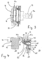
- Ein derzeit bevorzugtes Ausführungsbeispiel einer erfindungsgemäßen Vorrichtung in Gestalt einer Walzenpresse wird im Folgenden anhand der beigefügten, schematischen Zeichnungen näher erläutert, in denen:
- Figur 1
- eine räumliche Darstellung einer Walzenpresse mit der erfindungsgemäß verbesserten Abdichtung zwischen Produktraum und Antriebsseite ist,
- Figur 2
- eine Frontansicht auf die Walzenpresse der
Figur 1 von vorne ist, - Figur 3
- der Schnitt III-III aus
Figur 2 ist, und - Figur 4
- eine vergrößerte Darstellung eines Teils der
Figur 3 ist, die eine Dichtungseinheit im Detail zeigt. - In den Figuren ist eine allgemein mit 10 bezeichnete Walzenpresse zur Verwendung als Kompaktor® beispielsweise in der pharmazeutischen Industrie dargestellt. Die Walzenpresse 10 weist eine erste Walze 12 und eine zweite Walze 14 auf, die jeweils eine zylindrische Arbeitsfläche 12a und 14a haben und auf einer zugehörigen, ihrem Drehantrieb dienenden Welle befestigt sind, von denen eine Welle 13 in
Fig. 3 gezeigt ist. Die beiden Antriebswellen legen zueinander parallele Drehachsen 13a, 15a fest (sieheFig. 2 ), um die sich die Walzen 12, 14 im Betrieb gegenläufig drehen. - Jede Walze 12, 14 ist mittels eines zugehörigen Druckdeckels 16, 17 auf einem Abtriebsstummel 18 (siehe
Fig. 3 ) der zugehörigen Welle befestigt. Jeder Druckdeckel 16, 17 ist im gezeigten Ausführungsbeispiel mittels dreier Schrauben 20 auf dem zugehörigen Abtriebsstummel 18 festgeschraubt und verspannt die zugehörige Walze 12 bzw. 14 axial auf der entsprechenden Welle. Zur Abdichtung zwischen dem Druckdeckel 16 bzw. 17 und der ihm zugewandten Stirnseite jeder Walze 12 bzw. 14 ist der Außenrand der der Walze zugewandten Seite des Druckdeckels 16 bzw. 17 durch eine statische Lippendichtung 22 gebildet. Diese Lippendichtung 22 ermöglicht eine spaltfreie und damit totraumfreie Abdichtung zwischen dem Druckdeckel 16 bzw. 17 und der Stirnseite der zugehörigen Walze 12 bzw. 14, die Produktablagerungen in diesem Bereich verhindert und gut zu reinigen ist. - Zwischen sich bilden die beiden Walzen 12, 14 im Bereich ihrer Arbeitsflächen 12a, 14a einen Walzenspalt 24 (siehe
Fig. 2 ), dem pulverförmiges Material zugeführt werden kann, um es mittels der beim Durchlaufen des Walzenspalts 24 auftretenden Presswirkung zu granulieren. Damit das Ausmaß der Presswirkung im Walzenspalt 24 dem zu verarbeitenden Pulver und/oder Produkterfordernissen angepasst werden kann, kann der Abstand der beiden Drehachsen 13a, 15a voneinander im Betrieb verstellt werden. Im gezeigten Ausführungsbeispiel sind beide Drehachsen 13a, 15a mittels nicht gezeigter Einrichtungen verstellbar ausgebildet. - Jede den beiden Drehachsen 13a, 15a zugeordnete Welle (dargestellt ist nur die Welle 13) erstreckt sich von einer Antriebsseite 26 (siehe
Fig. 4 ) durch eine Wand 28 zu einer Produktseite bzw. in einen Produktraum 30, in dem sich die beiden Walzen 12, 14 befinden. Auf der Antriebsseite 26 befinden sich hier nicht weiter dargestellte Einrichtungen zum Drehantrieb der beiden die Walzen 12, 14 tragenden Wellen. - Um eine einwandfreie Abdichtung zwischen der Antriebsseite 26 und der Produktseite 30 zu gewährleisten und einen Eintrag von Fremdpartikeln in den Produktraum 30 möglichst zu unterbinden, ist die Welle 13 im Bereich der Wand 28 konzentrisch von einer Dichtungseinheit 32 umgeben, die als tragendes Element einen starren Grundkörper 34 aufweist, dessen Außendurchmesser deutlich kleiner als der Durchmesser einer Durchgangsöffnung 36 in der Wand 28 ist, durch die sich die Welle 13 erstreckt. Diese Durchmesserdifferenz erlaubt es, die Drehachse 13a der Welle 13 innerhalb des durch die Durchmesserdifferenz gegebenen Freiraumes radial zu verlagern und damit den Abstand zwischen den beiden Drehachsen 13a und 15a zu verändern. Der starre Grundkörper 34 der Dichtungseinheit 32 ist relativ zur Welle 13 fixiert, d.h. er verändert seine Relativposition zur Drehachse 13a bei einer Verstellung der Drehachse 13a nicht. Zur Produktseite 30 hin ist der starre Grundkörper 34 konisch verjüngend ausgebildet, um eine Produktablagerung auf seiner Außenseite zu erschweren.
- Der starre Grundkörper 34 hat eine zur Produktseite 30 hin offene, zur Drehachse 13a konzentrische Bohrung 38, in der axial hintereinander zwei Radiallippendichtungen 40 und 42 montiert sind, die als dynamische Wellenabdichtungen fungieren und hierzu an ihrer radial inneren Seite jeweils mit einer umlaufenden Dichtlippe 40a, 42a versehen sind, welche die Außenseite der Welle 13 kontaktieren. Die Dichtlippen 40a, 42a sind im Querschnitt gesehen so gebogen, dass zu den Radiallippendichtungen 40, 42 gelangendes Produkt von der Oberfläche der Welle 13 abgewiesen wird.
- Die axial innere Radiallippendichtung 42 ist in der Bohrung 38 mittels eines Spannringes 44 montiert, der in einer äußeren Umfangsnut 46 der Radiallippendichtung 42 aufgenommen ist. Der Spannring 46 hält die Radiallippendichtung 42 in der Bohrung 38 an Ort und Stelle fest und verhindert, dass bei sich drehender Welle 13 die Radiallippendichtung 42 sich ebenfalls dreht. Wie dargestellt, liegt die Radiallippendichtung 42 mit ihrem nahezu quadratischen Querschnitt am Grund der Bohrung 38 an.
- Die axial äußere Radiallippendichtung 40 mit ihrem ebenfalls nahezu quadratischen Querschnitt stützt sich über einen in der Bohrung 38 aufgenommenen Haltering 48 mit T-förmigem Querschnitt an der axial inneren Radiallippendichtung 42 ab. Eine Basis 50 des T-förmigen Querschnitts des Halterings 48 ist vollständig in der bezüglich der Bohrung 38 inneren Stirnseite der Radiallippendichtung 40 aufgenommen, wobei die Basis 50 breiter ist als der entsprechende, in der Radiallippendichtung 40 vorgesehene Aufnahmeschlitz, so dass bei auf dem Haltering 48 montierter Radiallippendichtung 40 aufgrund des Übermaßes der Basis 50 ein Aufspreizeffekt zur Wirkung kommt, der den im Querschnitt näherungsweise quadratischen Grundkörper der Radiallippendichtung 40 radial auswärts aufspreizt und dadurch in der Bohrung 38 festklemmt. Eine Verlagerung oder ein Drehen der Radiallippendichtung 40 im Betrieb wird auf diese Weise ausgeschlossen.
- Zur Abdichtung des aufgrund der genannten Durchmesserdifferenz zwischen dem starren Grundkörper 34 und der Durchgangsöffnung 36 in der Wand 28 bestehenden Ringspaltes dient eine statische Manschettendichtung 52, die im gezeigten Ausführungsbeispiel einen näherungsweise M-förmigen Querschnitt aufweist, der durch zwei äußere, verhältnismäßig dicke Schenkel 54, 56 und eine sich zwischen diesen Schenkeln erstreckende, den Freiraum zwischen ihnen überspannende, dünnere elastische Dichtmanschette 58 gebildet ist. Der radial innere Schenkel 54 dient zur Festlegung der Manschettendichtung 52 an der Dichtungseinheit 32 und ist hierzu nahezu vollständig in einem ersten Druckring 60 aufgenommen, der mittels nicht dargestellter Schrauben an der antriebsseitigen Stirnseite des starren Grundkörpers 34 befestigt ist und die freie Stirnseite des Schenkels 54 abdichtend gegen den Grundkörper 34 presst. In analoger Weise dient der Schenkel 56 zur Festlegung der Manschettendichtung 52 an der Wand 28 und ist hierzu ebenfalls nahezu vollständig in einem zweiten Druckring 62 aufgenommen, der an der Wand 28 befestigt ist und die freie Stirnseite des Schenkels 56 gegen die Wand 28 presst.
- Sowohl der erste Druckring 60 als auch der zweite Druckring 62 sind somit auf der Antriebsseite 26 angeordnet, wodurch ein zu verarbeitendes Produkt nur mit der elastischen Dichtmanschette 58 in Berührung kommen kann. Die elastische Dichtmanschette 58 ist dazu in der Lage, sich entsprechend der Verstellbewegung der Drehachse 13a zu verformen, ohne dabei zu reißen oder übermäßig auf Spannung oder Druck belastet zu werden. Sowohl die statische Manschettendichtung 52 als auch die Radiallippendichtungen 40 und 42 bestehen aus einem Elastomermaterial, welches eine ausreichende Beständigkeit gegenüber dem zu verarbeitenden Produkt aufweist und mechanisch ausreichend stabil ist. Geeignete Materialien sind dem Fachmann bekannt und werden deshalb hier nicht näher erläutert.
Claims (8)
- Vorrichtung, insbesondere Walzenpresse (10), mit zwei zumindest im Wesentlichen parallel zueinander angeordneten, drehbaren Wellen mit zugehörigen Drehachsen (13a, 15a), deren Abstand voneinander verstellbar ist, wobei die Wellen sich jeweils durch eine Wand (28) erstrecken, welche eine Antriebsseite von einer Produktseite trennt, und gegenüber der Wand (28) abgedichtet sind,
wobei- die Abdichtung zwischen jeder Welle (13) mit verstellbarer Drehachse und der Wand (28) mittels einer die zugehörige Welle (13) im Bereich der Wand (28) umgebenden Dichtungseinheit (32) erfolgt, die bei einer Verstellung der Drehachse ihre Relativposition zu dieser Drehachse beibehält, dadurch gekennzeichnet, dass- die Dichtungseinheit (32) radial innen eine dynamische Dichtung zur Abdichtung zwischen der drehbaren Welle (13) und der Dichtungseinheit (32) aufweist und radial außen eine statische Manschettendichtung (52) aufweist, die radial innen an der Dichtungseinheit (32) und radial außen an der Wand (28) abdichtend festgelegt ist und eine elastische Dichtmanschette (58) umfasst,wobei die statische Manschettendichtung (52) einen radial inneren Schenkel (54) aufweist, der in einem ersten Druckring (60) aufgenommen ist, der an einem Grundkörper (34) der Dichtungseinheit (32) befestigt ist, so dass eine Stirnseite des radial inneren Schenkels (54) mittels des ersten Druckrings (60) gegen den Grundkörper (34) der Dichtungseinheit (32) gepresst ist, und einen radial äußeren Schenkel (56) aufweist, der in einem zweiten Druckring (62) aufgenommen ist, der an der Wand (28) befestigt ist, wobei der erste Druckring (60) und der zweite Druckring (62) auf der Antriebsseite (26) der Vorrichtung angeordnet sind, so dass auf der Produktseite nur die elastische Dichtmanschette (58) dem Produkt ausgesetzt ist. - Vorrichtung nach Anspruch 1,
dadurch gekennzeichnet, dass die dynamische Dichtung zwei axial hintereinander angeordnete Dichtelemente aufweist. - Vorrichtung nach Anspruch 1 oder 2,
dadurch gekennzeichnet, dass die Dichtelemente Radiallippendichtungen (40, 42) sind. - Vorrichtung nach Anspruch 3,
dadurch gekennzeichnet, dass eine axial äußere der beiden Radiallippendichtungen (40, 42) axial auf einem Haltering (48) montiert ist, der die Radiallippendichtung (40) radial auswärts aufspreizt. - Vorrichtung nach Anspruch 4,
dadurch gekennzeichnet, dass der Haltering (48) einen T-förmigen Querschnitt hat und mit seiner Basis (50) in der Radiallippendichtung (40) steckt. - Vorrichtung nach einem der Ansprüche 2 bis 5,
dadurch gekennzeichnet, dass eine axial innere der beiden Radiallippendichtungen (40, 42) mittels eines Spannringes (44) montiert ist, der in einer äußeren Umfangsnut (46) der Radiallippendichtung (42) ruht. - Vorrichtung nach Anspruch 6,
dadurch gekennzeichnet, dass der Spannring (44) einen runden Querschnitt hat. - Vorrichtung nach einem der vorhergehenden Ansprüche,
dadurch gekennzeichnet, dass die statische Manschettendichtung (52) einen angenähert M-förmigen Querschnitt aufweist, mit zwei äußeren, dickeren Schenkeln (54, 56), die zur Festlegung der Manschettendichtung (52) an der Dichtungseinheit (32) und an der Wand (28) dienen, zwischen denen sich die elastische Dichtmanschette (58) erstreckt.
Applications Claiming Priority (2)
| Application Number | Priority Date | Filing Date | Title |
|---|---|---|---|
| DE102010018421.7A DE102010018421B4 (de) | 2010-04-27 | 2010-04-27 | Doppelwellenanordnung mit verstellbarem Achsabstand und verbesserter Dichtungseinheit |
| PCT/EP2011/001903 WO2011134606A1 (de) | 2010-04-27 | 2011-04-14 | Doppelwellenanordnung mit verstellbarem achsabstand und verbesserter dichtungseinheit |
Publications (2)
| Publication Number | Publication Date |
|---|---|
| EP2563578A1 EP2563578A1 (de) | 2013-03-06 |
| EP2563578B1 true EP2563578B1 (de) | 2015-07-15 |
Family
ID=44170404
Family Applications (1)
| Application Number | Title | Priority Date | Filing Date |
|---|---|---|---|
| EP11715438.5A Active EP2563578B1 (de) | 2010-04-27 | 2011-04-14 | Doppelwellenanordnung mit verstellbarem achsabstand und verbesserter dichtungseinheit |
Country Status (5)
| Country | Link |
|---|---|
| US (1) | US20140175752A1 (de) |
| EP (1) | EP2563578B1 (de) |
| CA (1) | CA2797462C (de) |
| DE (1) | DE102010018421B4 (de) |
| WO (1) | WO2011134606A1 (de) |
Families Citing this family (4)
| Publication number | Priority date | Publication date | Assignee | Title |
|---|---|---|---|---|
| DE102015211917B3 (de) | 2015-06-26 | 2016-08-04 | AMC Industrietechnik GmbH | Stopfbuchsgehäuse, insbesondere zur Verwendung in Mehrschneckenextrudern |
| EP3354433A1 (de) * | 2017-01-31 | 2018-08-01 | Covestro Deutschland AG | Vorrichtung mit freilaufenden kühlwalzen zur herstellung eines faserverbundwerkstoffs in form eines mit polymer imprägnierten faserbands, verfahren zur herstellung dieses faserbands, ein imprägniertes faserband und ein aus dem imprägnierten faserband hergestellter mehrschichtverbund |
| CN112747037B (zh) * | 2019-10-31 | 2023-04-07 | 新疆金风科技股份有限公司 | 轴系结构、密封组件以及风力发电机组 |
| CN114517836B (zh) * | 2022-01-14 | 2024-04-12 | 玺智达精密电子(深圳)有限公司 | 一种复合式遇水膨胀橡胶圈 |
Family Cites Families (20)
| Publication number | Priority date | Publication date | Assignee | Title |
|---|---|---|---|---|
| US3068051A (en) * | 1960-08-08 | 1962-12-11 | Koch Franz | Bearings for rollers in troughs or tanks containing liquid |
| NL267832A (de) * | 1960-12-27 | |||
| CH483574A (de) * | 1967-09-26 | 1969-12-31 | Benninger Ag Maschf | Lagerung für eine in einem Flüssigkeitsbehälter drehende Walze |
| US3941396A (en) * | 1974-08-15 | 1976-03-02 | Caterpillar Tractor Co. | Seal for rotating means |
| DE2558331A1 (de) * | 1975-12-23 | 1977-07-07 | Kloeckner Humboldt Deutz Ag | Wellendichtung zum gasdichten abschliessen von drehbeweglich gelagerten maschinenteilen |
| US4085941A (en) * | 1976-06-11 | 1978-04-25 | Crane Packing Limited | Stern seals for ships |
| JPS5951190A (ja) * | 1982-09-17 | 1984-03-24 | Hitachi Ltd | オイルフリ−スクリユ−圧縮機の油切り装置 |
| US4588195A (en) * | 1985-11-22 | 1986-05-13 | Dana Corporation | Floating lip seal assembly with convoluted flexible section |
| DE3834785C1 (en) * | 1988-10-12 | 1989-05-24 | Gebr. Kaiser Maschinenfabrik, 4150 Krefeld, De | Apparatus for generating granules or pellets from flowable material |
| DE9213374U1 (de) * | 1992-10-05 | 1994-02-10 | Martin Merkel GmbH & Co KG, 21107 Hamburg | Dichtring |
| US5639098A (en) * | 1994-10-03 | 1997-06-17 | Duramax, Inc. | Adjustable seal for propeller drive shaft |
| US6050572A (en) * | 1998-03-09 | 2000-04-18 | Bal Seal Engineering Company, Inc. | Rotary cartridge seals with retainer |
| DE29910508U1 (de) * | 1999-06-17 | 1999-10-28 | Prezetak, Manfred, 47918 Tönisvorst | Wellendichtring |
| DE20119265U1 (de) * | 2001-11-27 | 2002-02-21 | Main-Metall-Giesserei Fritz Schorr GmbH & Co. KG, 66885 Altenglan | Gleitlagerung für eine Walze, insbesondere eine Walze in einer Mühle zur Verarbeitung von Zuckerrohr |
| US6866271B2 (en) * | 2002-02-05 | 2005-03-15 | Duramax Marine, Llc | Marine shaft seal with lip seal, bearing and gasket |
| JP4918258B2 (ja) * | 2003-05-02 | 2012-04-18 | 株式会社小松製作所 | 軸受シール及び回動装置 |
| CN101052832B (zh) * | 2004-11-02 | 2011-12-07 | 株式会社小松制作所 | 轴承密封件 |
| US20070007731A1 (en) * | 2005-07-11 | 2007-01-11 | Zahn Henry W | Double lip dust excluder fork seal |
| JP4844489B2 (ja) * | 2007-07-19 | 2011-12-28 | 株式会社豊田自動織機 | 流体機械 |
| DE102008025373B3 (de) * | 2008-05-27 | 2009-09-17 | Hosokawa Bepex Gmbh | Vorrichtung zur Gutbettzerkleinerung |
-
2010
- 2010-04-27 DE DE102010018421.7A patent/DE102010018421B4/de not_active Expired - Fee Related
-
2011
- 2011-04-14 CA CA2797462A patent/CA2797462C/en not_active Expired - Fee Related
- 2011-04-14 EP EP11715438.5A patent/EP2563578B1/de active Active
- 2011-04-14 WO PCT/EP2011/001903 patent/WO2011134606A1/de not_active Ceased
- 2011-04-14 US US13/643,713 patent/US20140175752A1/en not_active Abandoned
Also Published As
| Publication number | Publication date |
|---|---|
| DE102010018421B4 (de) | 2016-06-09 |
| DE102010018421A1 (de) | 2011-10-27 |
| US20140175752A1 (en) | 2014-06-26 |
| EP2563578A1 (de) | 2013-03-06 |
| CA2797462A1 (en) | 2011-11-03 |
| WO2011134606A1 (de) | 2011-11-03 |
| CA2797462C (en) | 2015-12-01 |
Similar Documents
| Publication | Publication Date | Title |
|---|---|---|
| WO1987006991A1 (fr) | Dispositif d'etancheite | |
| DE2801711A1 (de) | Wellendichtung und verfahren zu ihrer herstellung | |
| DE102010018421B4 (de) | Doppelwellenanordnung mit verstellbarem Achsabstand und verbesserter Dichtungseinheit | |
| EP1122471A2 (de) | Dichtanordnung zwischen zwei relativ zueinander drehenden Bauteilen | |
| DE4216306C2 (de) | Drehübertrager für Druckmaschinen | |
| EP1370376A1 (de) | Dichtungsvorrichtung für walzenlager mit ausgleich radialen versatzes | |
| DE3445236C1 (de) | Dichtvorrichtung fuer den Verschluss eines aus Metall bestehenden Hochvakuumventils | |
| DE2354113A1 (de) | Dichtung | |
| DE2926498C2 (de) | Überdruckventil für einen Grubenstempel | |
| DE9213374U1 (de) | Dichtring | |
| DE29510331U1 (de) | Zuspannvorrichtung einer Scheibenbremse | |
| EP2504591A2 (de) | Kassettendichtung für radiallager und installationsverfahren | |
| EP1539388A1 (de) | Dichtungsvorrichtung mit eineim zweiteiligen ringk rper | |
| WO2008049524A1 (de) | Bandschleuse | |
| EP1206655B1 (de) | Wellenabdichtung für einen co2-kompressor | |
| DE102008063117B4 (de) | Druckmaschinenlageranordnung | |
| DE102010041611A1 (de) | Radial-Wellendichtring | |
| EP3728819B1 (de) | Dichtungsanordnung | |
| EP4350177B1 (de) | Hygienegerechtes dichtelement | |
| DE202008002709U1 (de) | Lageranordnung | |
| DE4038619C2 (de) | Anordnung zum Abdichten eines Zwischenraumes | |
| DE3008491A1 (de) | Gleitringdichtung | |
| DE102005053622B4 (de) | Axial-Radial-Lager, insbesondere für einen Rundtisch einer Werkzeugmaschine | |
| DE19532549A1 (de) | Wellenabdichtung | |
| DE102022121387B4 (de) | Hochdruckwalzenpresse mit Seitenwandanordnung |
Legal Events
| Date | Code | Title | Description |
|---|---|---|---|
| PUAI | Public reference made under article 153(3) epc to a published international application that has entered the european phase |
Free format text: ORIGINAL CODE: 0009012 |
|
| 17P | Request for examination filed |
Effective date: 20121025 |
|
| AK | Designated contracting states |
Kind code of ref document: A1 Designated state(s): AL AT BE BG CH CY CZ DE DK EE ES FI FR GB GR HR HU IE IS IT LI LT LU LV MC MK MT NL NO PL PT RO RS SE SI SK SM TR |
|
| DAX | Request for extension of the european patent (deleted) | ||
| GRAJ | Information related to disapproval of communication of intention to grant by the applicant or resumption of examination proceedings by the epo deleted |
Free format text: ORIGINAL CODE: EPIDOSDIGR1 |
|
| GRAP | Despatch of communication of intention to grant a patent |
Free format text: ORIGINAL CODE: EPIDOSNIGR1 |
|
| RAP1 | Party data changed (applicant data changed or rights of an application transferred) |
Owner name: HOSOKAWA ALPINE AKTIENGESELLSCHAFT |
|
| GRAP | Despatch of communication of intention to grant a patent |
Free format text: ORIGINAL CODE: EPIDOSNIGR1 |
|
| RAP1 | Party data changed (applicant data changed or rights of an application transferred) |
Owner name: HOSOKAWA ALPINE AKTIENGESELLSCHAFT |
|
| INTG | Intention to grant announced |
Effective date: 20141114 |
|
| GRAP | Despatch of communication of intention to grant a patent |
Free format text: ORIGINAL CODE: EPIDOSNIGR1 |
|
| INTG | Intention to grant announced |
Effective date: 20150106 |
|
| GRAS | Grant fee paid |
Free format text: ORIGINAL CODE: EPIDOSNIGR3 |
|
| GRAP | Despatch of communication of intention to grant a patent |
Free format text: ORIGINAL CODE: EPIDOSNIGR1 |
|
| GRAA | (expected) grant |
Free format text: ORIGINAL CODE: 0009210 |
|
| INTG | Intention to grant announced |
Effective date: 20150528 |
|
| AK | Designated contracting states |
Kind code of ref document: B1 Designated state(s): AL AT BE BG CH CY CZ DE DK EE ES FI FR GB GR HR HU IE IS IT LI LT LU LV MC MK MT NL NO PL PT RO RS SE SI SK SM TR |
|
| REG | Reference to a national code |
Ref country code: CH Ref legal event code: EP Ref country code: GB Ref legal event code: FG4D Free format text: NOT ENGLISH |
|
| REG | Reference to a national code |
Ref country code: IE Ref legal event code: FG4D Free format text: LANGUAGE OF EP DOCUMENT: GERMAN |
|
| REG | Reference to a national code |
Ref country code: AT Ref legal event code: REF Ref document number: 736568 Country of ref document: AT Kind code of ref document: T Effective date: 20150815 |
|
| REG | Reference to a national code |
Ref country code: DE Ref legal event code: R096 Ref document number: 502011007334 Country of ref document: DE |
|
| REG | Reference to a national code |
Ref country code: NL Ref legal event code: MP Effective date: 20150715 |
|
| REG | Reference to a national code |
Ref country code: LT Ref legal event code: MG4D |
|
| PG25 | Lapsed in a contracting state [announced via postgrant information from national office to epo] |
Ref country code: FI Free format text: LAPSE BECAUSE OF FAILURE TO SUBMIT A TRANSLATION OF THE DESCRIPTION OR TO PAY THE FEE WITHIN THE PRESCRIBED TIME-LIMIT Effective date: 20150715 Ref country code: NO Free format text: LAPSE BECAUSE OF FAILURE TO SUBMIT A TRANSLATION OF THE DESCRIPTION OR TO PAY THE FEE WITHIN THE PRESCRIBED TIME-LIMIT Effective date: 20151015 Ref country code: GR Free format text: LAPSE BECAUSE OF FAILURE TO SUBMIT A TRANSLATION OF THE DESCRIPTION OR TO PAY THE FEE WITHIN THE PRESCRIBED TIME-LIMIT Effective date: 20151016 Ref country code: LT Free format text: LAPSE BECAUSE OF FAILURE TO SUBMIT A TRANSLATION OF THE DESCRIPTION OR TO PAY THE FEE WITHIN THE PRESCRIBED TIME-LIMIT Effective date: 20150715 Ref country code: LV Free format text: LAPSE BECAUSE OF FAILURE TO SUBMIT A TRANSLATION OF THE DESCRIPTION OR TO PAY THE FEE WITHIN THE PRESCRIBED TIME-LIMIT Effective date: 20150715 |
|
| PG25 | Lapsed in a contracting state [announced via postgrant information from national office to epo] |
Ref country code: SE Free format text: LAPSE BECAUSE OF FAILURE TO SUBMIT A TRANSLATION OF THE DESCRIPTION OR TO PAY THE FEE WITHIN THE PRESCRIBED TIME-LIMIT Effective date: 20150715 Ref country code: PL Free format text: LAPSE BECAUSE OF FAILURE TO SUBMIT A TRANSLATION OF THE DESCRIPTION OR TO PAY THE FEE WITHIN THE PRESCRIBED TIME-LIMIT Effective date: 20150715 Ref country code: PT Free format text: LAPSE BECAUSE OF FAILURE TO SUBMIT A TRANSLATION OF THE DESCRIPTION OR TO PAY THE FEE WITHIN THE PRESCRIBED TIME-LIMIT Effective date: 20151116 Ref country code: HR Free format text: LAPSE BECAUSE OF FAILURE TO SUBMIT A TRANSLATION OF THE DESCRIPTION OR TO PAY THE FEE WITHIN THE PRESCRIBED TIME-LIMIT Effective date: 20150715 Ref country code: ES Free format text: LAPSE BECAUSE OF FAILURE TO SUBMIT A TRANSLATION OF THE DESCRIPTION OR TO PAY THE FEE WITHIN THE PRESCRIBED TIME-LIMIT Effective date: 20150715 Ref country code: RS Free format text: LAPSE BECAUSE OF FAILURE TO SUBMIT A TRANSLATION OF THE DESCRIPTION OR TO PAY THE FEE WITHIN THE PRESCRIBED TIME-LIMIT Effective date: 20150715 |
|
| REG | Reference to a national code |
Ref country code: DE Ref legal event code: R097 Ref document number: 502011007334 Country of ref document: DE |
|
| PG25 | Lapsed in a contracting state [announced via postgrant information from national office to epo] |
Ref country code: DK Free format text: LAPSE BECAUSE OF FAILURE TO SUBMIT A TRANSLATION OF THE DESCRIPTION OR TO PAY THE FEE WITHIN THE PRESCRIBED TIME-LIMIT Effective date: 20150715 Ref country code: EE Free format text: LAPSE BECAUSE OF FAILURE TO SUBMIT A TRANSLATION OF THE DESCRIPTION OR TO PAY THE FEE WITHIN THE PRESCRIBED TIME-LIMIT Effective date: 20150715 Ref country code: SK Free format text: LAPSE BECAUSE OF FAILURE TO SUBMIT A TRANSLATION OF THE DESCRIPTION OR TO PAY THE FEE WITHIN THE PRESCRIBED TIME-LIMIT Effective date: 20150715 Ref country code: IT Free format text: LAPSE BECAUSE OF FAILURE TO SUBMIT A TRANSLATION OF THE DESCRIPTION OR TO PAY THE FEE WITHIN THE PRESCRIBED TIME-LIMIT Effective date: 20150715 Ref country code: CZ Free format text: LAPSE BECAUSE OF FAILURE TO SUBMIT A TRANSLATION OF THE DESCRIPTION OR TO PAY THE FEE WITHIN THE PRESCRIBED TIME-LIMIT Effective date: 20150715 |
|
| PLBE | No opposition filed within time limit |
Free format text: ORIGINAL CODE: 0009261 |
|
| STAA | Information on the status of an ep patent application or granted ep patent |
Free format text: STATUS: NO OPPOSITION FILED WITHIN TIME LIMIT |
|
| PG25 | Lapsed in a contracting state [announced via postgrant information from national office to epo] |
Ref country code: RO Free format text: LAPSE BECAUSE OF FAILURE TO SUBMIT A TRANSLATION OF THE DESCRIPTION OR TO PAY THE FEE WITHIN THE PRESCRIBED TIME-LIMIT Effective date: 20150715 |
|
| 26N | No opposition filed |
Effective date: 20160418 |
|
| PG25 | Lapsed in a contracting state [announced via postgrant information from national office to epo] |
Ref country code: IS Free format text: LAPSE BECAUSE OF FAILURE TO SUBMIT A TRANSLATION OF THE DESCRIPTION OR TO PAY THE FEE WITHIN THE PRESCRIBED TIME-LIMIT Effective date: 20150715 |
|
| PG25 | Lapsed in a contracting state [announced via postgrant information from national office to epo] |
Ref country code: SI Free format text: LAPSE BECAUSE OF FAILURE TO SUBMIT A TRANSLATION OF THE DESCRIPTION OR TO PAY THE FEE WITHIN THE PRESCRIBED TIME-LIMIT Effective date: 20150715 Ref country code: BE Free format text: LAPSE BECAUSE OF NON-PAYMENT OF DUE FEES Effective date: 20160430 |
|
| GBPC | Gb: european patent ceased through non-payment of renewal fee |
Effective date: 20160414 |
|
| PG25 | Lapsed in a contracting state [announced via postgrant information from national office to epo] |
Ref country code: LU Free format text: LAPSE BECAUSE OF FAILURE TO SUBMIT A TRANSLATION OF THE DESCRIPTION OR TO PAY THE FEE WITHIN THE PRESCRIBED TIME-LIMIT Effective date: 20160414 |
|
| REG | Reference to a national code |
Ref country code: IE Ref legal event code: MM4A |
|
| REG | Reference to a national code |
Ref country code: FR Ref legal event code: ST Effective date: 20161230 |
|
| PG25 | Lapsed in a contracting state [announced via postgrant information from national office to epo] |
Ref country code: GB Free format text: LAPSE BECAUSE OF NON-PAYMENT OF DUE FEES Effective date: 20160414 Ref country code: FR Free format text: LAPSE BECAUSE OF NON-PAYMENT OF DUE FEES Effective date: 20160502 |
|
| PG25 | Lapsed in a contracting state [announced via postgrant information from national office to epo] |
Ref country code: IE Free format text: LAPSE BECAUSE OF NON-PAYMENT OF DUE FEES Effective date: 20160414 |
|
| REG | Reference to a national code |
Ref country code: AT Ref legal event code: MM01 Ref document number: 736568 Country of ref document: AT Kind code of ref document: T Effective date: 20160414 |
|
| PG25 | Lapsed in a contracting state [announced via postgrant information from national office to epo] |
Ref country code: NL Free format text: LAPSE BECAUSE OF FAILURE TO SUBMIT A TRANSLATION OF THE DESCRIPTION OR TO PAY THE FEE WITHIN THE PRESCRIBED TIME-LIMIT Effective date: 20150715 |
|
| PG25 | Lapsed in a contracting state [announced via postgrant information from national office to epo] |
Ref country code: AT Free format text: LAPSE BECAUSE OF NON-PAYMENT OF DUE FEES Effective date: 20160414 |
|
| PG25 | Lapsed in a contracting state [announced via postgrant information from national office to epo] |
Ref country code: CY Free format text: LAPSE BECAUSE OF FAILURE TO SUBMIT A TRANSLATION OF THE DESCRIPTION OR TO PAY THE FEE WITHIN THE PRESCRIBED TIME-LIMIT Effective date: 20150715 Ref country code: SM Free format text: LAPSE BECAUSE OF FAILURE TO SUBMIT A TRANSLATION OF THE DESCRIPTION OR TO PAY THE FEE WITHIN THE PRESCRIBED TIME-LIMIT Effective date: 20150715 Ref country code: HU Free format text: LAPSE BECAUSE OF FAILURE TO SUBMIT A TRANSLATION OF THE DESCRIPTION OR TO PAY THE FEE WITHIN THE PRESCRIBED TIME-LIMIT; INVALID AB INITIO Effective date: 20110414 |
|
| PG25 | Lapsed in a contracting state [announced via postgrant information from national office to epo] |
Ref country code: MC Free format text: LAPSE BECAUSE OF FAILURE TO SUBMIT A TRANSLATION OF THE DESCRIPTION OR TO PAY THE FEE WITHIN THE PRESCRIBED TIME-LIMIT Effective date: 20150715 Ref country code: TR Free format text: LAPSE BECAUSE OF FAILURE TO SUBMIT A TRANSLATION OF THE DESCRIPTION OR TO PAY THE FEE WITHIN THE PRESCRIBED TIME-LIMIT Effective date: 20150715 Ref country code: MT Free format text: LAPSE BECAUSE OF FAILURE TO SUBMIT A TRANSLATION OF THE DESCRIPTION OR TO PAY THE FEE WITHIN THE PRESCRIBED TIME-LIMIT Effective date: 20150715 Ref country code: MK Free format text: LAPSE BECAUSE OF FAILURE TO SUBMIT A TRANSLATION OF THE DESCRIPTION OR TO PAY THE FEE WITHIN THE PRESCRIBED TIME-LIMIT Effective date: 20150715 |
|
| PG25 | Lapsed in a contracting state [announced via postgrant information from national office to epo] |
Ref country code: BG Free format text: LAPSE BECAUSE OF FAILURE TO SUBMIT A TRANSLATION OF THE DESCRIPTION OR TO PAY THE FEE WITHIN THE PRESCRIBED TIME-LIMIT Effective date: 20150715 |
|
| PG25 | Lapsed in a contracting state [announced via postgrant information from national office to epo] |
Ref country code: AL Free format text: LAPSE BECAUSE OF FAILURE TO SUBMIT A TRANSLATION OF THE DESCRIPTION OR TO PAY THE FEE WITHIN THE PRESCRIBED TIME-LIMIT Effective date: 20150715 |
|
| P01 | Opt-out of the competence of the unified patent court (upc) registered |
Effective date: 20230515 |
|
| PGFP | Annual fee paid to national office [announced via postgrant information from national office to epo] |
Ref country code: DE Payment date: 20250425 Year of fee payment: 15 |
|
| PGFP | Annual fee paid to national office [announced via postgrant information from national office to epo] |
Ref country code: CH Payment date: 20250501 Year of fee payment: 15 |
|
| REG | Reference to a national code |
Ref country code: CH Ref legal event code: U11 Free format text: ST27 STATUS EVENT CODE: U-0-0-U10-U11 (AS PROVIDED BY THE NATIONAL OFFICE) Effective date: 20260501 |