EP2562529B1 - Composite structure having an embedded sensing system - Google Patents
Composite structure having an embedded sensing system Download PDFInfo
- Publication number
- EP2562529B1 EP2562529B1 EP12181606.0A EP12181606A EP2562529B1 EP 2562529 B1 EP2562529 B1 EP 2562529B1 EP 12181606 A EP12181606 A EP 12181606A EP 2562529 B1 EP2562529 B1 EP 2562529B1
- Authority
- EP
- European Patent Office
- Prior art keywords
- optical fiber
- signals
- quantum dots
- composite structure
- composite
- Prior art date
- Legal status (The legal status is an assumption and is not a legal conclusion. Google has not performed a legal analysis and makes no representation as to the accuracy of the status listed.)
- Active
Links
Images


Classifications
-
- G—PHYSICS
- G01—MEASURING; TESTING
- G01M—TESTING STATIC OR DYNAMIC BALANCE OF MACHINES OR STRUCTURES; TESTING OF STRUCTURES OR APPARATUS, NOT OTHERWISE PROVIDED FOR
- G01M11/00—Testing of optical apparatus; Testing structures by optical methods not otherwise provided for
- G01M11/08—Testing mechanical properties
- G01M11/083—Testing mechanical properties by using an optical fiber in contact with the device under test [DUT]
- G01M11/086—Details about the embedment of the optical fiber within the DUT
-
- G—PHYSICS
- G01—MEASURING; TESTING
- G01B—MEASURING LENGTH, THICKNESS OR SIMILAR LINEAR DIMENSIONS; MEASURING ANGLES; MEASURING AREAS; MEASURING IRREGULARITIES OF SURFACES OR CONTOURS
- G01B11/00—Measuring arrangements characterised by the use of optical techniques
- G01B11/16—Measuring arrangements characterised by the use of optical techniques for measuring the deformation in a solid, e.g. optical strain gauge
- G01B11/18—Measuring arrangements characterised by the use of optical techniques for measuring the deformation in a solid, e.g. optical strain gauge using photoelastic elements
-
- G—PHYSICS
- G01—MEASURING; TESTING
- G01N—INVESTIGATING OR ANALYSING MATERIALS BY DETERMINING THEIR CHEMICAL OR PHYSICAL PROPERTIES
- G01N21/00—Investigating or analysing materials by the use of optical means, i.e. using sub-millimetre waves, infrared, visible or ultraviolet light
- G01N21/84—Systems specially adapted for particular applications
- G01N2021/8472—Investigation of composite materials
Definitions
- Embodiments of the present disclosure relate generally to composite structures and, more particularly, to composite structures having embedded sensing systems for monitoring the health of a composite material.
- Composite structures are structures consisting of two or more components often with some imparted order which are utilized in a wide variety of applications.
- air vehicles such as aircraft, spacecraft or the like
- composite structures may utilize composite structures in order to take advantage of the benefits attributable to the increased strength-to-weight ratio offered by composite materials.
- Other applications that may include composite structures include other types of vehicles, such as automobiles, marine vehicles, bicycles and the like, as well as a wide variety of other structures, such as buildings, bridges, etc.
- Composite structures may also be produced and used with additional functionalities including altered thermal, electrical, acoustical, or mechanical properties by suitably modifying the materials used, the structure itself, or the process used to produce the structure.
- Composite structures may be fabricated in various manners designed to impart a predetermined order to a plurality of elements dispersed within a resin or other mostly continuous medium, e.g, polymer, glass, or cement.
- a composite structure includes a plurality of structural fibers, such as glass fibers or other elements including carbon fibers, metalized carbon fibers, metal or polymer sheets, carbon or polymer veils, pre-impregnated composite sheets, woven sheets of fibers, matts of random or organized fibers, metal or polymer meshes, embedded in a resin matrix.
- the resin matrix may be any one of many thermoplastic or thermoset polymer combinations, adhesives or other bonding materials, or cement.
- the composite structure may be cured, melted or bonded in one or more processing steps.
- composite structures offer a number of advantages
- composite structures may occasionally have various anomalies, such as delamination between composite plies, waviness within the composite plies or marcelling in which a composite tow rolls at least partially on top of itself so as to create an inner swirl within the composite structure. While some of these anomalies may be detected from a visual inspection of the composite structure, a number of the anomalies may reside within the interior of the composite structure so as not to be detected during a visual inspection of the composite structure. As such, a variety of inspection techniques utilizing, for example, x-rays, ultrasonic signals or the like have been developed in order to interrogate the interior of a composite structure.
- While these inspection techniques may detect a number of anomalies, such as ply delaminations, other anomalies that may be created by the misorientation or misplacement of the structural fibers within the resin of a composite structure may present more of a challenge from a detection standpoint.
- the plurality of structural fibers or other elements within a composite structure generally extends in a predefined direction with the physical properties of the composite structure depending, at least in part, upon the directionality of the structural fibers or other elements.
- the structural fibers or other elements within a composite structure may assume a different and an unintended orientation or position which may cause the physical properties of the composite structure to also be different.
- the structural fibers or other included elements that extend proximate a resin-rich area may migrate or move toward or into the resin-rich area, thereby deviating from their intended orientation.
- the unintended orientation or position of the structural fibers may be the result of gravity, hydrostatic pressure, chemical or boiling action or mechanical action.
- European patent application EP 1519181 describes a detection system for a structural composite material including an optical fiber.
- US patent application US 2008/0085086 described the application of quantum dots to provide light amplification and sensing functions within optical fibers having holes therein.
- the embedded sensing system includes optical fiber having a plurality of quantum dots that enhance the non-linear optical properties of the optical fiber.
- defects or other current or past changes or states within the composite structure may cause the quantum dots to create a non-linear effect that is readily discernible, thereby providing a reliable indicator of a defect within the composite structure.
- a system and a method for monitoring the health of a composite structure are also provided according to embodiments to the present disclosure.
- the health of a composite structure includes its chemical state, e.g., degree of cure, its mechanical state, e.g.
- strain field its environment, e.g., temperature or moisture content, presence of flaws or porosity, e.g., disbonds or ply dislocations, its thermal or electrical properties, or ion density, any of which may have a bearing on the ability of the structure to complete its mission.
- a system for monitoring a composite structure comprising: a composite structure; an optical fiber within the composite structure; a signal source coupled to the optical fiber configured to provide signals to the optical fiber for propagation therealong; and a detector coupled to the optical fiber configured to detect signals that exit the optical fiber, wherein the optical fiber includes a plurality of quantum dots configured to create a non-linear effect, e.g.
- the signal source is configured to provide two distinct input frequencies ⁇ 1 and ⁇ 2 , wherein at least one of ⁇ 1 , ⁇ 2 , ⁇ 1 + ⁇ 2 or ⁇ 1 - ⁇ 2 is resonant with one or more material parameters of the optical fiber, and the system further comprises a reflector positioned at the second end of the optical fiber so as to reflect the signals through the optical fiber from the second end toward the first end, and wherein the detector is responsive to signals emitted by the first end of the optical fiber following reflection of the signals therethrough.
- the core may include the plurality of quantum dots so to amplify signals propagating through the core and/or enhance the sensitivity of the optical fiber.
- the cladding of the optical fiber may include the plurality of quantum dots in order to enhance interaction with the surrounding resin via a fiber evanescent wave.
- the plurality of quantum dots may be disposed upon a surface of the optical fiber in order to provide for stronger interaction with the local strain field, material and evanescent wave. Since the non-linear effect may be readily identified, the system of this embodiment may reliably detect defects in the composite material so as to facilitate further inspection or repair. For example, defects such as deviations in the path of a fiber tow or composite ply may be detected along with, in some embodiments, the location of such defects.
- the optical fiber may include a Bragg grating or one or more partially reflecting mirrors for causing reflection of at least some of the signals.
- a method for monitoring the health of a composite structure comprising: providing signals from a signal source to the optical fiber for propagation therealong; detecting signals that exit the optical fiber; wherein the method further comprises reflecting the signals at the reflector so as to reflect the signals through the optical fiber from the second end toward the first end, and wherein the step of detecting comprises detecting signals emitted by the first end of the optical fiber following reflection of the signals therethrough, and the method further comprises identifying the presence of a non-linear effect in the detected signal and identifying a defect in the composite structure in response to identifying the presence of the non-linear effect.
- the core may include the plurality of quantum dots so to amplify signals propagating through the core and/or enhance the sensitivity of the optical fiber.
- the cladding of the optical fiber may include the plurality of quantum dots in order to enhance interaction with the surrounding resin via a fiber evanescent wave.
- the plurality of quantum dots may be disposed upon a surface of the optical fiber in order to provide for stronger interaction with the local strain field, material and evanescent wave.
- the composite structure 10 may be utilized in a variety of applications including in air vehicles, such as aircraft, spacecraft or the like, land vehicles, such as automobiles, trucks, trailers, bicycles, etc., marine vehicles, buildings and other structures.
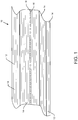
- the composite structure 10 includes a composite material having a plurality of structural elements 12 embedded within a matrix of resin 14.
- the composite material may include a number of different types of structural elements 12 including structural fibers such as glass fibers, carbon fibers or the like and other elements such as graphene sheets, a carbon veil, a woven prepreg, a solid sheet and a metal or polymer mesh.
- the composite material may include a number of different types of resin 14 including, for example, epoxy resin, polyester resin or the like.
- the composite material includes a plurality of composite plies, each having the plurality of structural elements 12 embedded within the matrix of resin 14.
- the composite plies may be laid one upon the other as shown in Figure 1 .
- the composite material may be fabricated in other manners including, for example, a plurality of composite tows that are laid beside one another or by including sheets, veils, pre-impregnated cloth, metal or polymer mesh or the like.
- the composite material is laid up or formed so as to have a desired shape, such as by laying the composite plies or composite tows or other elements upon a mandrel or tool having the desired shape.
- one or more optical fibers 16 including a plurality of quantum dots 18 is disposed within the composite material, such as by being embedded within the composite material, as also shown in Figure 1 .
- the optical fiber 16 is disposed within the composite material in such a manner that at least one end of the optical fiber and, more typically, both of the opposed ends of the optical fiber are accessible, such as by extending to an edge, such as opposed edges, of the composite material. While a single optical fiber 16 is shown in Figure 1 , the composite structure 10 may include a plurality of optical fibers which may, in one embodiment, extend parallel to one another through the composite material.
- the optical fiber 16 may be positioned between composite plies, composite tows, or the like. Once the optical fiber 16 has been disposed within the composite material, the composite material may be cured or otherwise processed to solidify the resin 14 such that the composite material retains the shape in which the composite plies or composite tows were laid up. This curing or other solidification of the composite material also serves to secure the optical fiber 16 within the composite material such that the optical fiber extends therethrough.
- the optical fiber 16 that is disposed within the composite material includes a plurality of quantum dots 18. While a plurality of quantum dots 18 are shown within the optical fiber 16 of Figure 1 , the quantum dots are illustrated to be larger than typical for purposes of illustration, but not of example.
- the optical fiber 16 of one embodiment is formed to include the quantum dots 18 by implanting spectroscopically enhancing features within the optical fiber or by inducing microscopic structural changes within the optical fiber which cause enhancements to the hyperpolarizability of the optical fiber. As described below, the plurality of quantum dots 18 enhance the non-linear optical properties of the optical fiber 16 relative to a comparable optical fiber that does not include quantum dots.
- spectroscopic enhancement in the case of nonlinear optics diverges somewhat from the traditional linear case.
- linear spectroscopy light will be more readily absorbed by a material when the light frequency matches that associated with a material excitation. Once that light is absorbed, it may be re-emitted or thermalized within the material, depending on the rest of the material parameters.
- the nonlinear case it is not necessary for all or any of the light input frequencies to coincide with material excitations to produce a spectroscopic enhancement of the effect in question.
- neither of the two inputs may coincide with a material excitation, but if the frequency difference coincides with a material excitation, the efficiency of light production at the difference frequency will be enhanced.
- the case of second harmonic generation may have an input signal that is not resonant, but if the second harmonic frequency coincides with a material excitation, the second harmonic generation process will be enhanced.
- the input frequencies to the optical fiber may be selected to allow the nonlinear processes to be resonant with one of more of the material excitations. For example, if there are two distinct input frequencies ⁇ 1 and ⁇ 2 , then ⁇ 1 can be resonant, or ⁇ 2 can be resonant, or ⁇ 1 + ⁇ 2 can be resonant, or ⁇ 1 - ⁇ 2 can be resonant with one or more of the material parameters. Additionally, several of the combinations may be resonant simultaneously.
- the optical fiber with the quantum dots can be doped with materials that provide a material resonance.
- the material with which the optical fiber is doped could be, but is not limited to, atomic or molecular species that have known spectral features.
- a fiber that is physically strained will have local molecular bonds strained.
- straining molecular bonds will increase their nonlinear response through a larger hyperpolarizibility.
- a physically strained material will have a net orientation introduced at a molecular level which will also increase the net cumulative effect of the hyperpolarizibility. The combination of these two effects will lead to a larger nonlinear optical response, even if pure spectroscopic enhancements are unavailable.
- the optical fiber 16 may include quantum dots 18 in one or more regions of the optical fiber.
- the optical fiber 16 of one embodiment may include a core 16a surrounded by cladding 16b having a different coefficient of refraction than the core so as to largely confine the signals propagating through the core within the core.
- the quantum dots 18 are included within the core 16a of the optical fiber 16.
- the quantum dots 18 within the core 16a of the optical fiber 16 may serve to amplify signals propagating through the core of the optical fiber and to enhance the sensitivity of the optical fiber to defects within the composite material.
- the optical fiber 16 may include quantum dots at the interface between the core 16a and the cladding 16b.
- the optical fiber 16 may include the quantum dots 18 within the cladding 16b, thereby enhancing the interaction of the signals propagating through the optical fiber with the surrounding composite material via fiber evanescent waves.
- the optical fiber 16 may include a plurality of quantum dots 18 on the outer surface 16c of the optical fiber, such as the outer surface of the cladding.
- the plurality of quantum dots 18 disposed upon the outer surface of the optical fiber 16 may interact more strongly with the local strain field in the composite material via evanescent waves.
- the optical fiber 16 may include the plurality of quantum dots 18 in only one of these regions, that is, only one of the core 16a, the cladding 16b or the outer surface 16c of the optical fiber.
- the optical fiber 16 may include the plurality of the quantum dots 18 in any two of these regions, such as any two of the core 16a, the cladding 16b or the outer surface 16c of the not of example.
- the optical fiber 16 of one embodiment is formed to include the quantum dots 18 by implanting spectroscopically enhancing features within the optical fiber or by inducing microscopic structural changes within the optical fiber which cause enhancements to the hyperpolarizability of the optical fiber.
- the plurality of quantum dots 18 enhance the non-linear optical properties of the optical fiber 16 relative to a comparable optical fiber that does not include quantum dots.
- spectroscopic enhancement in the case of nonlinear optics diverges somewhat from the traditional linear case.
- linear spectroscopy light will be more readily absorbed by a material when the light frequency matches that associated with a material excitation. Once that light is absorbed, it may be re-emitted or thermalized within the material, depending on the rest of the material parameters.
- the nonlinear case it is not necessary for all or any of the light input frequencies to coincide with material excitations to produce a spectroscopic enhancement of the effect in question.
- neither of the two inputs may coincide with a material excitation, but if the frequency difference coincides with a material excitation, the efficiency of light production at the difference frequency will be enhanced.
- the case of second harmonic generation may have an input signal that is not resonant, but if the second harmonic frequency coincides with a material excitation, the second harmonic generation process will be enhanced.
- the input frequencies to the optical fiber are selected to allow the nonlinear processes to be resonant with one of more of the material excitations.
- There are two distinct input frequencies ⁇ 1 and ⁇ 2 then ⁇ 1 can be resonant, or ⁇ 2 can be resonant, or ⁇ 1 + ⁇ 2 can be resonant, or ⁇ 1 - ⁇ 2 can be resonant with one or more of the material parameters. Additionally, several of the combinations may be resonant simultaneously.
- the optical fiber with the quantum dots can be doped with materials that provide a material resonance.
- the material with which the optical fiber is doped could be, but is not limited to, atomic or molecular species that have known spectral features.
- a fiber that is physically strained will have local molecular bonds strained.
- straining molecular bonds will increase their nonlinear response through a larger hyperpolarizibility.
- a physically strained material will have a net orientation introduced at a molecular level which will also increase the net cumulative effect of the hyperpolarizibility. The combination of these two effects will lead to a larger nonlinear optical response, even if pure spectroscopic enhancements are unavailable.
- the optical fiber 16 includes quantum dots 18 in one or more regions of the optical fiber.
- the optical fiber 16 of one embodiment may include a core 16a surrounded by cladding 16b having a different coefficient of refraction than the core so as to largely confine the signals propagating through the core within the core.
- the quantum dots 18 are included within the core 16a of the optical fiber 16.
- the quantum dots 18 within the core 16a of the optical fiber 16 may serve to amplify signals propagating through the core of the optical fiber and to enhance the sensitivity of the optical fiber to defects within the composite material.
- the optical fiber 16 may include quantum dots at the interface between the core 16a and the cladding 16b.
- the optical fiber 16 may include the quantum dots 18 within the cladding 16b, thereby enhancing the interaction of the signals propagating through the optical fiber with the surrounding composite material via fiber evanescent waves.
- the optical fiber 16 may include a plurality of quantum dots 18 on the outer surface 16c of the optical fiber, such as the outer surface of the cladding.
- the plurality of quantum dots 18 disposed upon the outer surface of the optical fiber 16 may interact more strongly with the local strain field in the composite material via evanescent waves.
- the optical fiber 16 may include the plurality of quantum dots 18 in only one of these regions, that is, only one of the core 16a, the cladding 16b or the outer surface 16c of the optical fiber.
- the optical fiber 16 may include the plurality of the quantum dots 18 in any two of these regions, such as any two of the core 16a, the cladding 16b or the outer surface 16c of the optical fiber or, in some embodiments, may include the plurality of quantum dots in all three of these regions, that is, in each of the core, the cladding, and the outer surface of the optical fiber.
- the optical fiber 16 may be a gradient index fiber that includes quantum dots 18 such that reference herein to the core of an optical fiber including quantum dots is also intended to encompass the embodiment in which a gradient index fiber includes quantum dots.
- the optical fiber 16 may be a light pipe having a hollow core for supporting the propagation of infrared (IR) or other signals therealong.
- the optical fiber 16 also includes a plurality of quantum dots 18.
- the plurality of quantum dots 18 may be disposed upon an inner surface of the light pipe that faces and defines the hollow core.
- optical fibers 16 are described above, the foregoing examples are not meant to be all inclusive and other types of optical fibers may be employed including elliptical core optical fibers, multi-hole optical fibers, multi-core optical fibers and optical fibers having a myriad of other internal or surface structures that can impact the environment of any nearby quantum dots disposed within or on the optical fiber.
- the optical fiber may include quantum dots in a relatively uniform manner along its length or may only include quantum dots in one or more discrete segments along the length of the optical fiber.
- the optical fiber 16 may be more sensitive to defects in the composite material that are proximate to a segment of the optical fiber that includes quantum dots 18 relative to a segment of the optical fiber that does not include quantum dots.
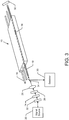
- a system in accordance with the present disclosure not only includes the composite structure 10 including the composite material and the embedded optical fiber 16, but also includes a signal source 20, such as an optical source, for providing signals to the optical fiber for propagation therealong.
- the signal source 20 is configured to introduce signals via the first end of the optical fiber 16 for propagation along the length of the optical fiber toward the second end of the optical fiber.
- the system may include various types of signal sources 20 for introducing various types of signals for propagation along the optical fiber
- the signal source of one embodiment is a laser, such as a pulsed laser, for providing laser signals to the optical fiber 16 for propagation therethrough.
- the signal source 20 may be an IR signal source for providing IR signals to the first end of the optical fiber.
- the signal source 20 may provide the signals directly to the optical fiber 16, such as to the first end of the optical fiber. As shown in Figure 3 , however, the signals generated by the signal source may be conditioned prior to being delivered to the optical fiber 16.
- the system may include a wavelength selection device 22, such as a wavelength filter, for filtering the signals generated by the signal source 20 to insure that signals having only one or more predefined frequencies or a predefined range of frequency pass through the wavelength selection device for delivery to the optical fiber 16.
- the system may also include a polarization device 24, such as a Glan Taylor prism, a Glan Thompson prism, a Wollaston prism, a thin film polarizer, in combination with waveplates, including thin film devices or optically active materials, such as quartz, for limiting the signals that propagate beyond the polarization device to those having one or more predefined polarizations.
- a polarization device such as a Glan Taylor prism, a Glan Thompson prism, a Wollaston prism, a thin film polarizer, in combination with waveplates, including thin film devices or optically active materials, such as quartz, for limiting the signals that propagate beyond the polarization device to those having one or more predefined polarizations.
- the system may include an intensity filter 26, such as a neutral density filter, a color filter, variable attenuation devices such as wedge pairs or matched prisms, or other fixed or variable optical attenuation devices, for limiting the energy carried by the signals that are to be provided to the
- the system of the illustrated embodiment includes each of the wavelength selection device 22, the polarization sensitive device 24 and the intensity filter 26, the system may include any one or any combination of these elements in other embodiments.
- the system may also include an optical device 28, such as a lens, for focusing the signals upon the first end of the optical fiber 16, such as by matching the signals to the numerical aperture of the optical fiber.
- the system also includes a detector 30 configured to receive the signals including any non-linear effects generated from the signals following propagation through the optical fiber 16, such as following fabrication of the composite structure 10 such that the composite structure is as-cured or during the fabrication of the composite structure so as to provide in-process monitoring.
- the system is configured such that the signals are reflected and returned to the first end of the optical fiber 16.
- the detector 30 is positioned so as to receive the signals as well as non-linear effects created by the signals upon their exit from the first end of the optical fiber 16.
- a beam splitter 34 may be positioned to receive the reflected signals and to redirect the reflected signals that exit the first end of the optical fiber 16 to the detector 30.
- the detector 30 may receive the signals exiting the first end of the optical fiber 16 even though the detector is offset or out of linear alignment with the optical fiber, thereby facilitating the introduction of the signals from the signal source 20 into the first end of the optical fiber without being obstructed by the detector.
- the system may include various types of detectors including a solid state detector, such as a photodiode.
- the detector may be formed of a material that is selected and based upon the wavelength of the signals to be detected since, for example, semiconductor photodiodes generally detect signals having a predefined range of wavelengths that can be absorbed by the semiconductor material.
- a silicon photodiode may be utilized to detect the returning signals and the associated non-linear effects.
- the detector may include an avalanche photodiode (APD).
- the signals propagating along the optical fiber 16 may be reflected in various manners.
- the system includes a reflector 32, such as a mirror, for receiving the signals reaching the second end of the optical fiber 16 and for reflecting the signals such that the signals and the associated non-linear effects are returned to the optical fiber and propagate from the second end toward the first end for receipt and detection by the detector 30.
- the optical fiber 16 may include a Bragg grating 36 or other types of reflectors such as partially reflecting mirrors, e.g., a Fabry-Perot etalon having one or more partially reflecting mirrors, formed within the optical fiber, such as described in U.S. Patent No.
- embodiments of the method may be employed in conjunction with a composite structure 10 in an uncured state.
- an optical fiber 16 including a plurality of quantum dots 18 may be embedded within a composite structure 10 in an uncured state. Once the optical fiber 16 has been embedded in the composite structure 10, signals may be provided to the optical fiber for propagation therealong until the composite structure achieves a cured state. See block 62. Signals exiting the optical fiber 16 may then be detected until the composite structure 10 achieves the cured state. See block 64.
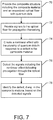
- a method may therefore be provided for monitoring the health of a composite structure 10 as shown, for example, in the flowchart of Figure 7 .
- the system and method of embodiments of the present disclosure may monitor the health of the composite structure during its fabrication prior to curing or other solidification of the resin, thereby providing in-process monitoring.
- the system and method of one embodiment could monitor a composite structure that did not cure or solidify in order to monitor the orientation of the plies or fiber tows.
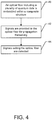
- the composite structure 10 including a composite material and one or more optical fibers 16 disposed within the composite material may be provided, as shown in operation 70 of Figure 7 .
- the optical fiber 16 includes a plurality of quantum dots 18 for enhancing the non-linear optical properties of the optical fiber.
- signals may then be provided to the optical fiber 16 for propagation therealong, such as from a first end into which the signals are introduced toward an opposed second end.
- a defect in the composite material such as a defect that may cause the optical fibers to bend in an unanticipated manner or to otherwise result in unanticipated amounts of stress or strain being placed upon the optical fibers, a non-linear effect may be created by the plurality of quantum dots 18 as shown in operation 74.
- non-linear effects may be created including the creation of a second order effect, such as a generation of a second harmonic, the creation of a third order effect, such as a generation of a third order harmonic, or the like in response to the defect in the composite material.
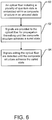
- the method may also detect signals, including the non-linear effect following propagation through the optical fiber 16, as shown in operation 76. By analyzing the signals including the non-linear effect, such as by means of the detector 30 or a computer associated with and responsive to the detector, instances in which the composite material has a defect that has altered the signals propagating through the optical fiber 16 and has created non-linear effects may be identified. See operation 78.
- deviations in the path of a fiber tow and deviations in the position or path of a composite ply may be detected in accordance with one embodiment of the present disclosure. Additionally, the location of the defect may also be determined, such as based upon TDR, in some embodiments. Based upon the detection of a potential defect within the composite material, the method of one embodiment may provide for further testing and analysis of the potential defect and/or for making appropriate repairs to the composite material so as to repair the defect.
- the signals and the associated non-linear effects that are detected may be compared, such as by the detector 30 or an associated computer, to the signals and associated non-linear effects that are otherwise expected to be detected following propagation of the signal through the optical fiber 16 in an instance in which the composite material does not include any defects.
- the method may identify a potential defect within the composite material so as to allow for more detailed analysis and/or repair of the composite material or to inform the user of the need to alter the mission.
- the system and method of one embodiment may facilitate the detection of a defect within a composite material so as to permit the composite material to be further analyzed or inspected and/or to promote more focused repair of the composite material in a timely manner or otherwise respond to the new knowledge.
- the analysis of the non-linear effects created by the plurality of quantum dots 18 in response to a defect in the composite material may permit defects to be identified in a reliable manner that is not limited by the relatively low signal to noise ratio that may otherwise impair an analysis that is simply based upon the reflected signals within the optical fiber 16 without consideration of the associated non-linear effects.
- the health of a composite material may be monitored by embedding a plurality of optical fibers 16, such as an array of optical fibers, that include quantum dots 18 within the composite material.
- the signals and associated non-linear effects that are detected by detector 30 following signal propagation through the array of optical fibers may provide multi-dimensional data, such as two dimensional (2D) or three dimensional (3D) data indicative of the health of the composite material by providing, for example, an indication of deviations in the location of a fiber tow or composite ply and, in some embodiments utilizing optical time domain reflectometry, the location of such deviations.
- the detector 30 may be configured to display a visual representation of this multi-dimensional data, such as by overlaying a visual representation of the multi-dimensional data onto a model of the composite structure 10 that is being fabricated such that the model can provide a reference for the multi-dimensional data gathered by the system of this embodiment of the present disclosure.
Landscapes
- Physics & Mathematics (AREA)
- General Physics & Mathematics (AREA)
- Chemical & Material Sciences (AREA)
- Analytical Chemistry (AREA)
- Length Measuring Devices By Optical Means (AREA)
- Investigating Or Analysing Materials By Optical Means (AREA)
- Optical Transform (AREA)
- Testing Of Devices, Machine Parts, Or Other Structures Thereof (AREA)
Applications Claiming Priority (2)
| Application Number | Priority Date | Filing Date | Title |
|---|---|---|---|
| US13/215,969 US20130050685A1 (en) | 2011-08-23 | 2011-08-23 | Composite structure having an embedded sensing system |
| US13/562,832 US9170172B2 (en) | 2011-08-23 | 2012-07-31 | Composite structure having an embedded sensing system |
Publications (3)
| Publication Number | Publication Date |
|---|---|
| EP2562529A2 EP2562529A2 (en) | 2013-02-27 |
| EP2562529A3 EP2562529A3 (en) | 2015-10-07 |
| EP2562529B1 true EP2562529B1 (en) | 2017-10-11 |
Family
ID=47215346
Family Applications (1)
| Application Number | Title | Priority Date | Filing Date |
|---|---|---|---|
| EP12181606.0A Active EP2562529B1 (en) | 2011-08-23 | 2012-08-23 | Composite structure having an embedded sensing system |
Country Status (4)
| Country | Link |
|---|---|
| US (1) | US9170172B2 (enExample) |
| EP (1) | EP2562529B1 (enExample) |
| JP (1) | JP6058314B2 (enExample) |
| ES (1) | ES2706533T3 (enExample) |
Families Citing this family (23)
| Publication number | Priority date | Publication date | Assignee | Title |
|---|---|---|---|---|
| US11725088B2 (en) | 2014-09-30 | 2023-08-15 | The Boeing Company | Prepreg compositions, their manufacture, and determination of their suitability for use in composite structures |
| US9787916B2 (en) | 2014-10-28 | 2017-10-10 | The Boeing Company | Active real-time characterization system |
| US9534969B1 (en) * | 2015-11-24 | 2017-01-03 | The Boeing Company | System and method for tactile sensing using thin film optical sensing networks |
| US10416004B2 (en) * | 2016-05-02 | 2019-09-17 | Mitsubishi Electric Corporation | Resin impregnation detection device, coil for rotating machine, and method for impregnating and molding resin of coil for rotating machine |
| US10018569B2 (en) * | 2016-05-12 | 2018-07-10 | Northrop Grumman Systems Corporation | Optical fiber communications with composite structural monitoring for determining damaged structure based on the analysis of optical signal |
| US10401239B2 (en) | 2016-11-01 | 2019-09-03 | The Boeing Company | Integrated hyper-redundant tactile sensor network based on structural fibers |
| JP7237593B2 (ja) * | 2016-12-01 | 2023-03-13 | ヤマハ発動機株式会社 | 傾斜車両 |
| US10337935B2 (en) | 2016-12-12 | 2019-07-02 | Sikorsky Aircraft Corporation | Systems and methods for integrated, multi-functional, fault tolerant sensing and communication |
| US10877192B2 (en) | 2017-04-18 | 2020-12-29 | Saudi Arabian Oil Company | Method of fabricating smart photonic structures for material monitoring |
| US10401155B2 (en) | 2017-05-12 | 2019-09-03 | Saudi Arabian Oil Company | Apparatus and method for smart material analysis |
| US10746534B2 (en) | 2017-07-03 | 2020-08-18 | Saudi Arabian Oil Company | Smart coating device for storage tank monitoring and calibration |
| US10578562B2 (en) | 2018-02-22 | 2020-03-03 | The Boeing Company | Active real-time characterization system using radio-frequency radiation |
| US10424057B2 (en) | 2018-02-22 | 2019-09-24 | The Boeing Company | Active real-time characterization system for detecting physical imperfections during semiconductor manufacturing |
| US10712265B2 (en) | 2018-02-22 | 2020-07-14 | The Boeing Company | Active real-time characterization system providing spectrally broadband characterization |
| US10430936B2 (en) | 2018-02-22 | 2019-10-01 | The Boeing Company | Active real-time characterization system for identifying surface contamination |
| US10424056B2 (en) | 2018-02-22 | 2019-09-24 | The Boeing Company | Active real-time characterization system for monitoring absorption and curing rates of chemical substances |
| US10438337B2 (en) | 2018-02-22 | 2019-10-08 | The Boeing Company | Active real-time characterization system utilizing beam scanning for surface imaging |
| US11018761B2 (en) | 2019-05-01 | 2021-05-25 | Ultra Communications, Inc. | Automated system for link health assessment in fiber optic networks |
| EP3760418B1 (en) * | 2019-07-03 | 2022-06-01 | Airbus Operations, S.L.U. | System for monitoring resin flow |
| DE102020100058A1 (de) | 2020-01-03 | 2021-07-08 | Leoni Kabel Gmbh | Faseroptische Temperaturmessung mit Quantendot-Nanokomposit |
| WO2022144458A1 (en) | 2020-12-30 | 2022-07-07 | Tmg- Tecidos Para Vestuário E Decoração, S.A | Thermosetting material, methods and uses thereof |
| CN114894225B (zh) * | 2022-07-13 | 2022-09-30 | 安徽省国盛量子科技有限公司 | 基于光纤微弯技术的分布式光纤传感器及制作方法 |
| WO2025047077A1 (ja) * | 2023-08-28 | 2025-03-06 | 日本電信電話株式会社 | 測定システム、測定方法、及び、解析装置 |
Family Cites Families (41)
| Publication number | Priority date | Publication date | Assignee | Title |
|---|---|---|---|---|
| US5026141A (en) | 1981-08-24 | 1991-06-25 | G2 Systems Corporation | Structural monitoring system using fiber optics |
| GB2197946B (en) * | 1986-06-19 | 1989-12-20 | Pirelli General Plc | Sensing strain and temperature |
| US5026140A (en) | 1988-11-18 | 1991-06-25 | Mcdonnell-Douglas Corporation | Distortion-free fiber optic sensors embedded in titanium |
| US4936649A (en) * | 1989-01-25 | 1990-06-26 | Lymer John D | Damage evaluation system and method using optical fibers |
| US5319435A (en) | 1991-09-04 | 1994-06-07 | Melle Serge M | Method and apparatus for measuring the wavelength of spectrally narrow optical signals |
| US5513913A (en) | 1993-01-29 | 1996-05-07 | United Technologies Corporation | Active multipoint fiber laser sensor |
| US5299271A (en) | 1993-02-26 | 1994-03-29 | The United States Of America As Represented By The Secretary Of The Air Force | System and method of embedding optical fibers in honeycomb panels |
| US5293050A (en) | 1993-03-25 | 1994-03-08 | International Business Machines Corporation | Semiconductor quantum dot light emitting/detecting devices |
| US5627637A (en) | 1995-02-24 | 1997-05-06 | Kapteyn; Kelvin L. | Fully distributed optical fiber strain sensor |
| US5682237A (en) | 1995-05-26 | 1997-10-28 | McDonnell Douglas | Fiber strain sensor and system including one intrinsic and one extrinsic fabry-perot interferometer |
| US5770155A (en) * | 1995-11-21 | 1998-06-23 | United Technologies Corporation | Composite structure resin cure monitoring apparatus using an optical fiber grating sensor |
| US5633748A (en) | 1996-03-05 | 1997-05-27 | The United States Of America As Represented By The Secretary Of The Navy | Fiber optic Bragg grating demodulator and sensor incorporating same |
| GB9626099D0 (en) | 1996-12-16 | 1997-02-05 | King S College London | Distributed strain and temperature measuring system |
| US6204920B1 (en) | 1996-12-20 | 2001-03-20 | Mcdonnell Douglas Corporation | Optical fiber sensor system |
| GB9700269D0 (en) | 1997-01-08 | 1997-02-26 | York Sensors Ltd | Improvements to optical time domain reflectometry |
| US6004639A (en) | 1997-10-10 | 1999-12-21 | Fiberspar Spoolable Products, Inc. | Composite spoolable tube with sensor |
| US20020110180A1 (en) | 2001-02-09 | 2002-08-15 | Barney Alfred A. | Temperature-sensing composition |
| US6882051B2 (en) | 2001-03-30 | 2005-04-19 | The Regents Of The University Of California | Nanowires, nanostructures and devices fabricated therefrom |
| US7132676B2 (en) | 2001-05-15 | 2006-11-07 | Kabushiki Kaisha Toshiba | Photon source and a method of operating a photon source |
| US7005669B1 (en) | 2001-08-02 | 2006-02-28 | Ultradots, Inc. | Quantum dots, nanocomposite materials with quantum dots, devices with quantum dots, and related fabrication methods |
| US6819845B2 (en) | 2001-08-02 | 2004-11-16 | Ultradots, Inc. | Optical devices with engineered nonlinear nanocomposite materials |
| US20030066998A1 (en) | 2001-08-02 | 2003-04-10 | Lee Howard Wing Hoon | Quantum dots of Group IV semiconductor materials |
| US6978070B1 (en) * | 2001-08-14 | 2005-12-20 | The Programmable Matter Corporation | Fiber incorporating quantum dots as programmable dopants |
| US7054513B2 (en) | 2003-06-09 | 2006-05-30 | Virginia Tech Intellectual Properties, Inc. | Optical fiber with quantum dots |
| JP4377642B2 (ja) | 2003-09-26 | 2009-12-02 | 富士重工業株式会社 | 構造用複合材料の損傷探知システム |
| US7113660B2 (en) * | 2004-02-18 | 2006-09-26 | The Boeing Company | Fiber optic damage detection system for composite pressure vessels |
| GB0407386D0 (en) | 2004-03-31 | 2004-05-05 | British Telecomm | Monitoring a communications link |
| US7492463B2 (en) | 2004-04-15 | 2009-02-17 | Davidson Instruments Inc. | Method and apparatus for continuous readout of Fabry-Perot fiber optic sensor |
| US6930820B1 (en) | 2004-04-21 | 2005-08-16 | The Boeing Company | Embedded fiber optic demodulator |
| JP3848660B2 (ja) * | 2004-05-06 | 2006-11-22 | 川崎重工業株式会社 | 損傷検知装置 |
| ATE466268T1 (de) | 2004-12-28 | 2010-05-15 | Airbus Espana Sl | Verfahren zur überwachung von strukturschäden und ihr fortschritt in monolitischen verbundstrukturen mittels faser-bragg-gitter- sensoren |
| JP2008534981A (ja) * | 2005-04-05 | 2008-08-28 | エージェンシー フォー サイエンス,テクノロジー アンド リサーチ | 光ファイバ歪センサ |
| AU2005338588B2 (en) | 2005-11-30 | 2013-01-24 | Airbus Operations, S.L. | Composite material structure with embedded optical fibre and method for repairing same |
| US7623974B2 (en) | 2007-01-30 | 2009-11-24 | Pratt & Whitney Rocketdyne, Inc. | System and method for detecting onset of structural failure |
| AU2008280830B2 (en) | 2007-07-24 | 2014-02-20 | Adelaide Research & Innovation Pty Ltd | Optical fiber sensor |
| US8219180B2 (en) * | 2007-10-11 | 2012-07-10 | Tufts University | System and method employing fiber optic shape tracking |
| US8135244B1 (en) | 2007-11-14 | 2012-03-13 | The United States Of America As Represented By The United States Deparment Of Energy | Real time measurement of shock pressure |
| US7574074B1 (en) | 2008-08-18 | 2009-08-11 | An-Bin Huang | Method for detecting cracks in carbon fiber bicycle frame using embedded optical fiber |
| US8111385B2 (en) | 2009-01-26 | 2012-02-07 | The Boeing Company | Quantum dot-mediated optical fiber information retrieval systems and methods of use |
| JPWO2011033649A1 (ja) * | 2009-09-18 | 2013-02-07 | 公立大学法人高知工科大学 | 複数のセンシング領域を有する分布型光ファイバーセンサー装置 |
| US20130050685A1 (en) * | 2011-08-23 | 2013-02-28 | The Boeing Company | Composite structure having an embedded sensing system |
-
2012
- 2012-07-31 US US13/562,832 patent/US9170172B2/en active Active
- 2012-08-17 JP JP2012180703A patent/JP6058314B2/ja active Active
- 2012-08-23 ES ES12181606T patent/ES2706533T3/es active Active
- 2012-08-23 EP EP12181606.0A patent/EP2562529B1/en active Active
Non-Patent Citations (1)
| Title |
|---|
| None * |
Also Published As
| Publication number | Publication date |
|---|---|
| ES2706533T3 (es) | 2019-03-29 |
| US20130048841A1 (en) | 2013-02-28 |
| EP2562529A2 (en) | 2013-02-27 |
| US9170172B2 (en) | 2015-10-27 |
| EP2562529A3 (en) | 2015-10-07 |
| JP6058314B2 (ja) | 2017-01-11 |
| JP2013064729A (ja) | 2013-04-11 |
Similar Documents
| Publication | Publication Date | Title |
|---|---|---|
| EP2562529B1 (en) | Composite structure having an embedded sensing system | |
| EP2693187B1 (en) | Composite structure having an embedded sensing system | |
| US20130050685A1 (en) | Composite structure having an embedded sensing system | |
| Fu et al. | Impact source identification in a carbon fiber reinforced polymer plate by using embedded fiber optic acoustic emission sensors | |
| JP2014052368A5 (enExample) | ||
| Holmes et al. | Real-time through-thickness and in-plane strain measurement in Carbon Fibre Reinforced Polymer composites using planar optical Bragg grating | |
| Tian et al. | Guided wave propagation study on laminated composites by frequency-wavenumber technique | |
| Satori et al. | Development of small-diameter optical fiber sensors for damage detection in composite laminates | |
| JP2015232522A (ja) | 光ファイバセンサ装置 | |
| US20180209910A1 (en) | Inteferometric Sensor Basid on Slab Waveguide | |
| US11965732B2 (en) | Methods and sensor for measuring strain | |
| Majewska et al. | Assessment of delamination in composite beam using infrared thermography, optical sensors and terahertz technique | |
| JP4878013B2 (ja) | 亀裂発生位置の検出方法 | |
| Keulen et al. | Embedded fiber optic sensors for monitoring processing, quality and structural health of resin transfer molded components | |
| Qiu et al. | Free-space input and output coupling to an embedded fiber optic strain sensor: dual-ended interrogation via transmission | |
| Hu et al. | Refractive index sensing using all-dielectric metasurface with analogue of electromagnetically induced transparency | |
| Wei et al. | Direct laser writing of polymer micro-ring resonator ultrasonic sensors | |
| KR20110043834A (ko) | 분광기와 선형 배열 광감지기를 이용한 fbg 센서 복조화 장치 | |
| Epaarachchi et al. | The response of embedded NIR (830 nm) fiber Bragg grating sensors in glass fiber composites under fatigue loading | |
| Ramakrishnan et al. | 17 Optical Fiber Sensors for Smart Composite Materials and Structures | |
| Ramani et al. | An evaluation of the performance of a lens-based plastic optical fiber strain sensor | |
| Kostecki et al. | Optical fibres for distributed corrosion sensing-architecture and characterisation | |
| Jannesari et al. | Vertical coupling into a photonic crystal waveguide using band folding design | |
| Hudson | Real-time cure monitoring of composites using a guided wave-based system with high temperature piezoelectric transducers, fiber Bragg gratings, and phase-shifted fiber Bragg gratings | |
| Khan | Optic Fiber Sensor for Assessing Layer Waviness in Smart Structure |
Legal Events
| Date | Code | Title | Description |
|---|---|---|---|
| PUAI | Public reference made under article 153(3) epc to a published international application that has entered the european phase |
Free format text: ORIGINAL CODE: 0009012 |
|
| 17P | Request for examination filed |
Effective date: 20120823 |
|
| AK | Designated contracting states |
Kind code of ref document: A2 Designated state(s): AL AT BE BG CH CY CZ DE DK EE ES FI FR GB GR HR HU IE IS IT LI LT LU LV MC MK MT NL NO PL PT RO RS SE SI SK SM TR |
|
| AX | Request for extension of the european patent |
Extension state: BA ME |
|
| PUAL | Search report despatched |
Free format text: ORIGINAL CODE: 0009013 |
|
| AK | Designated contracting states |
Kind code of ref document: A3 Designated state(s): AL AT BE BG CH CY CZ DE DK EE ES FI FR GB GR HR HU IE IS IT LI LT LU LV MC MK MT NL NO PL PT RO RS SE SI SK SM TR |
|
| AX | Request for extension of the european patent |
Extension state: BA ME |
|
| RIC1 | Information provided on ipc code assigned before grant |
Ipc: G01M 11/08 20060101AFI20150903BHEP Ipc: G01B 11/16 20060101ALI20150903BHEP |
|
| 17Q | First examination report despatched |
Effective date: 20160629 |
|
| GRAP | Despatch of communication of intention to grant a patent |
Free format text: ORIGINAL CODE: EPIDOSNIGR1 |
|
| INTG | Intention to grant announced |
Effective date: 20170420 |
|
| GRAS | Grant fee paid |
Free format text: ORIGINAL CODE: EPIDOSNIGR3 |
|
| GRAA | (expected) grant |
Free format text: ORIGINAL CODE: 0009210 |
|
| AK | Designated contracting states |
Kind code of ref document: B1 Designated state(s): AL AT BE BG CH CY CZ DE DK EE ES FI FR GB GR HR HU IE IS IT LI LT LU LV MC MK MT NL NO PL PT RO RS SE SI SK SM TR |
|
| REG | Reference to a national code |
Ref country code: GB Ref legal event code: FG4D |
|
| REG | Reference to a national code |
Ref country code: CH Ref legal event code: EP |
|
| REG | Reference to a national code |
Ref country code: IE Ref legal event code: FG4D |
|
| REG | Reference to a national code |
Ref country code: AT Ref legal event code: REF Ref document number: 936474 Country of ref document: AT Kind code of ref document: T Effective date: 20171115 |
|
| REG | Reference to a national code |
Ref country code: DE Ref legal event code: R096 Ref document number: 602012038331 Country of ref document: DE |
|
| REG | Reference to a national code |
Ref country code: NL Ref legal event code: MP Effective date: 20171011 |
|
| REG | Reference to a national code |
Ref country code: LT Ref legal event code: MG4D |
|
| REG | Reference to a national code |
Ref country code: AT Ref legal event code: MK05 Ref document number: 936474 Country of ref document: AT Kind code of ref document: T Effective date: 20171011 |
|
| PG25 | Lapsed in a contracting state [announced via postgrant information from national office to epo] |
Ref country code: NL Free format text: LAPSE BECAUSE OF FAILURE TO SUBMIT A TRANSLATION OF THE DESCRIPTION OR TO PAY THE FEE WITHIN THE PRESCRIBED TIME-LIMIT Effective date: 20171011 |
|
| PG25 | Lapsed in a contracting state [announced via postgrant information from national office to epo] |
Ref country code: ES Free format text: LAPSE BECAUSE OF FAILURE TO SUBMIT A TRANSLATION OF THE DESCRIPTION OR TO PAY THE FEE WITHIN THE PRESCRIBED TIME-LIMIT Effective date: 20171011 Ref country code: SE Free format text: LAPSE BECAUSE OF FAILURE TO SUBMIT A TRANSLATION OF THE DESCRIPTION OR TO PAY THE FEE WITHIN THE PRESCRIBED TIME-LIMIT Effective date: 20171011 Ref country code: NO Free format text: LAPSE BECAUSE OF FAILURE TO SUBMIT A TRANSLATION OF THE DESCRIPTION OR TO PAY THE FEE WITHIN THE PRESCRIBED TIME-LIMIT Effective date: 20180111 Ref country code: LT Free format text: LAPSE BECAUSE OF FAILURE TO SUBMIT A TRANSLATION OF THE DESCRIPTION OR TO PAY THE FEE WITHIN THE PRESCRIBED TIME-LIMIT Effective date: 20171011 Ref country code: FI Free format text: LAPSE BECAUSE OF FAILURE TO SUBMIT A TRANSLATION OF THE DESCRIPTION OR TO PAY THE FEE WITHIN THE PRESCRIBED TIME-LIMIT Effective date: 20171011 |
|
| PG25 | Lapsed in a contracting state [announced via postgrant information from national office to epo] |
Ref country code: LV Free format text: LAPSE BECAUSE OF FAILURE TO SUBMIT A TRANSLATION OF THE DESCRIPTION OR TO PAY THE FEE WITHIN THE PRESCRIBED TIME-LIMIT Effective date: 20171011 Ref country code: BG Free format text: LAPSE BECAUSE OF FAILURE TO SUBMIT A TRANSLATION OF THE DESCRIPTION OR TO PAY THE FEE WITHIN THE PRESCRIBED TIME-LIMIT Effective date: 20180111 Ref country code: HR Free format text: LAPSE BECAUSE OF FAILURE TO SUBMIT A TRANSLATION OF THE DESCRIPTION OR TO PAY THE FEE WITHIN THE PRESCRIBED TIME-LIMIT Effective date: 20171011 Ref country code: GR Free format text: LAPSE BECAUSE OF FAILURE TO SUBMIT A TRANSLATION OF THE DESCRIPTION OR TO PAY THE FEE WITHIN THE PRESCRIBED TIME-LIMIT Effective date: 20180112 Ref country code: AT Free format text: LAPSE BECAUSE OF FAILURE TO SUBMIT A TRANSLATION OF THE DESCRIPTION OR TO PAY THE FEE WITHIN THE PRESCRIBED TIME-LIMIT Effective date: 20171011 Ref country code: IS Free format text: LAPSE BECAUSE OF FAILURE TO SUBMIT A TRANSLATION OF THE DESCRIPTION OR TO PAY THE FEE WITHIN THE PRESCRIBED TIME-LIMIT Effective date: 20180211 Ref country code: RS Free format text: LAPSE BECAUSE OF FAILURE TO SUBMIT A TRANSLATION OF THE DESCRIPTION OR TO PAY THE FEE WITHIN THE PRESCRIBED TIME-LIMIT Effective date: 20171011 |
|
| REG | Reference to a national code |
Ref country code: DE Ref legal event code: R097 Ref document number: 602012038331 Country of ref document: DE |
|
| PG25 | Lapsed in a contracting state [announced via postgrant information from national office to epo] |
Ref country code: SK Free format text: LAPSE BECAUSE OF FAILURE TO SUBMIT A TRANSLATION OF THE DESCRIPTION OR TO PAY THE FEE WITHIN THE PRESCRIBED TIME-LIMIT Effective date: 20171011 Ref country code: DK Free format text: LAPSE BECAUSE OF FAILURE TO SUBMIT A TRANSLATION OF THE DESCRIPTION OR TO PAY THE FEE WITHIN THE PRESCRIBED TIME-LIMIT Effective date: 20171011 Ref country code: EE Free format text: LAPSE BECAUSE OF FAILURE TO SUBMIT A TRANSLATION OF THE DESCRIPTION OR TO PAY THE FEE WITHIN THE PRESCRIBED TIME-LIMIT Effective date: 20171011 Ref country code: CZ Free format text: LAPSE BECAUSE OF FAILURE TO SUBMIT A TRANSLATION OF THE DESCRIPTION OR TO PAY THE FEE WITHIN THE PRESCRIBED TIME-LIMIT Effective date: 20171011 |
|
| PLBE | No opposition filed within time limit |
Free format text: ORIGINAL CODE: 0009261 |
|
| STAA | Information on the status of an ep patent application or granted ep patent |
Free format text: STATUS: NO OPPOSITION FILED WITHIN TIME LIMIT |
|
| REG | Reference to a national code |
Ref country code: FR Ref legal event code: PLFP Year of fee payment: 7 |
|
| PG25 | Lapsed in a contracting state [announced via postgrant information from national office to epo] |
Ref country code: IT Free format text: LAPSE BECAUSE OF FAILURE TO SUBMIT A TRANSLATION OF THE DESCRIPTION OR TO PAY THE FEE WITHIN THE PRESCRIBED TIME-LIMIT Effective date: 20171011 Ref country code: RO Free format text: LAPSE BECAUSE OF FAILURE TO SUBMIT A TRANSLATION OF THE DESCRIPTION OR TO PAY THE FEE WITHIN THE PRESCRIBED TIME-LIMIT Effective date: 20171011 Ref country code: SM Free format text: LAPSE BECAUSE OF FAILURE TO SUBMIT A TRANSLATION OF THE DESCRIPTION OR TO PAY THE FEE WITHIN THE PRESCRIBED TIME-LIMIT Effective date: 20171011 Ref country code: PL Free format text: LAPSE BECAUSE OF FAILURE TO SUBMIT A TRANSLATION OF THE DESCRIPTION OR TO PAY THE FEE WITHIN THE PRESCRIBED TIME-LIMIT Effective date: 20171011 |
|
| 26N | No opposition filed |
Effective date: 20180712 |
|
| PG25 | Lapsed in a contracting state [announced via postgrant information from national office to epo] |
Ref country code: SI Free format text: LAPSE BECAUSE OF FAILURE TO SUBMIT A TRANSLATION OF THE DESCRIPTION OR TO PAY THE FEE WITHIN THE PRESCRIBED TIME-LIMIT Effective date: 20171011 |
|
| REG | Reference to a national code |
Ref country code: ES Ref legal event code: NE2A Effective date: 20190322 |
|
| PG25 | Lapsed in a contracting state [announced via postgrant information from national office to epo] |
Ref country code: MC Free format text: LAPSE BECAUSE OF FAILURE TO SUBMIT A TRANSLATION OF THE DESCRIPTION OR TO PAY THE FEE WITHIN THE PRESCRIBED TIME-LIMIT Effective date: 20171011 |
|
| REG | Reference to a national code |
Ref country code: ES Ref legal event code: FG2A Ref document number: 2706533 Country of ref document: ES Kind code of ref document: T3 Effective date: 20190329 Ref country code: CH Ref legal event code: PL |
|
| PG25 | Lapsed in a contracting state [announced via postgrant information from national office to epo] |
Ref country code: LI Free format text: LAPSE BECAUSE OF NON-PAYMENT OF DUE FEES Effective date: 20180831 Ref country code: ES Free format text: LAPSE BECAUSE OF FAILURE TO SUBMIT A TRANSLATION OF THE DESCRIPTION OR TO PAY THE FEE WITHIN THE PRESCRIBED TIME-LIMIT Effective date: 20171011 Ref country code: CH Free format text: LAPSE BECAUSE OF NON-PAYMENT OF DUE FEES Effective date: 20180831 Ref country code: LU Free format text: LAPSE BECAUSE OF NON-PAYMENT OF DUE FEES Effective date: 20180823 |
|
| PGRI | Patent reinstated in contracting state [announced from national office to epo] |
Ref country code: ES Effective date: 20190322 |
|
| REG | Reference to a national code |
Ref country code: BE Ref legal event code: MM Effective date: 20180831 |
|
| PG25 | Lapsed in a contracting state [announced via postgrant information from national office to epo] |
Ref country code: BE Free format text: LAPSE BECAUSE OF NON-PAYMENT OF DUE FEES Effective date: 20180831 |
|
| PG25 | Lapsed in a contracting state [announced via postgrant information from national office to epo] |
Ref country code: MT Free format text: LAPSE BECAUSE OF NON-PAYMENT OF DUE FEES Effective date: 20180823 |
|
| PG25 | Lapsed in a contracting state [announced via postgrant information from national office to epo] |
Ref country code: TR Free format text: LAPSE BECAUSE OF FAILURE TO SUBMIT A TRANSLATION OF THE DESCRIPTION OR TO PAY THE FEE WITHIN THE PRESCRIBED TIME-LIMIT Effective date: 20171011 |
|
| PG25 | Lapsed in a contracting state [announced via postgrant information from national office to epo] |
Ref country code: HU Free format text: LAPSE BECAUSE OF FAILURE TO SUBMIT A TRANSLATION OF THE DESCRIPTION OR TO PAY THE FEE WITHIN THE PRESCRIBED TIME-LIMIT; INVALID AB INITIO Effective date: 20120823 Ref country code: PT Free format text: LAPSE BECAUSE OF FAILURE TO SUBMIT A TRANSLATION OF THE DESCRIPTION OR TO PAY THE FEE WITHIN THE PRESCRIBED TIME-LIMIT Effective date: 20171011 |
|
| PG25 | Lapsed in a contracting state [announced via postgrant information from national office to epo] |
Ref country code: CY Free format text: LAPSE BECAUSE OF FAILURE TO SUBMIT A TRANSLATION OF THE DESCRIPTION OR TO PAY THE FEE WITHIN THE PRESCRIBED TIME-LIMIT Effective date: 20171011 Ref country code: IE Free format text: LAPSE BECAUSE OF NON-PAYMENT OF DUE FEES Effective date: 20180823 Ref country code: MK Free format text: LAPSE BECAUSE OF NON-PAYMENT OF DUE FEES Effective date: 20171011 |
|
| PG25 | Lapsed in a contracting state [announced via postgrant information from national office to epo] |
Ref country code: AL Free format text: LAPSE BECAUSE OF FAILURE TO SUBMIT A TRANSLATION OF THE DESCRIPTION OR TO PAY THE FEE WITHIN THE PRESCRIBED TIME-LIMIT Effective date: 20171011 |
|
| P01 | Opt-out of the competence of the unified patent court (upc) registered |
Effective date: 20230516 |
|
| PGFP | Annual fee paid to national office [announced via postgrant information from national office to epo] |
Ref country code: ES Payment date: 20250901 Year of fee payment: 14 |
|
| PGFP | Annual fee paid to national office [announced via postgrant information from national office to epo] |
Ref country code: DE Payment date: 20250827 Year of fee payment: 14 |
|
| PGFP | Annual fee paid to national office [announced via postgrant information from national office to epo] |
Ref country code: GB Payment date: 20250827 Year of fee payment: 14 |
|
| PGFP | Annual fee paid to national office [announced via postgrant information from national office to epo] |
Ref country code: FR Payment date: 20250825 Year of fee payment: 14 |