EP2562443A1 - Engine unit and two-wheeled motor vehicle with same - Google Patents
Engine unit and two-wheeled motor vehicle with same Download PDFInfo
- Publication number
- EP2562443A1 EP2562443A1 EP11771772A EP11771772A EP2562443A1 EP 2562443 A1 EP2562443 A1 EP 2562443A1 EP 11771772 A EP11771772 A EP 11771772A EP 11771772 A EP11771772 A EP 11771772A EP 2562443 A1 EP2562443 A1 EP 2562443A1
- Authority
- EP
- European Patent Office
- Prior art keywords
- clutch
- gear
- main shaft
- shaft
- transmission
- Prior art date
- Legal status (The legal status is an assumption and is not a legal conclusion. Google has not performed a legal analysis and makes no representation as to the accuracy of the status listed.)
- Withdrawn
Links
- 230000005540 biological transmission Effects 0.000 claims abstract description 155
- 230000007246 mechanism Effects 0.000 claims description 53
- 238000005192 partition Methods 0.000 claims description 9
- 230000002441 reversible effect Effects 0.000 description 26
- 239000010687 lubricating oil Substances 0.000 description 15
- 238000010586 diagram Methods 0.000 description 13
- 230000001105 regulatory effect Effects 0.000 description 8
- 230000008859 change Effects 0.000 description 7
- 238000003825 pressing Methods 0.000 description 7
- 230000002829 reductive effect Effects 0.000 description 6
- 239000007858 starting material Substances 0.000 description 6
- 230000005484 gravity Effects 0.000 description 5
- 230000002093 peripheral effect Effects 0.000 description 5
- 230000009467 reduction Effects 0.000 description 5
- 230000036961 partial effect Effects 0.000 description 4
- 230000000630 rising effect Effects 0.000 description 4
- 238000012423 maintenance Methods 0.000 description 3
- 230000000994 depressogenic effect Effects 0.000 description 2
- 230000000694 effects Effects 0.000 description 2
- 239000002828 fuel tank Substances 0.000 description 2
- 230000000670 limiting effect Effects 0.000 description 2
- 206010021580 Inadequate lubrication Diseases 0.000 description 1
- 241000826860 Trapezium Species 0.000 description 1
- 230000008901 benefit Effects 0.000 description 1
- 230000008878 coupling Effects 0.000 description 1
- 238000010168 coupling process Methods 0.000 description 1
- 238000005859 coupling reaction Methods 0.000 description 1
- 230000007423 decrease Effects 0.000 description 1
- 230000003247 decreasing effect Effects 0.000 description 1
- 230000006872 improvement Effects 0.000 description 1
- 238000004519 manufacturing process Methods 0.000 description 1
- 239000000463 material Substances 0.000 description 1
- 238000000034 method Methods 0.000 description 1
- 230000007935 neutral effect Effects 0.000 description 1
- 239000003921 oil Substances 0.000 description 1
- 238000011084 recovery Methods 0.000 description 1
- 230000004044 response Effects 0.000 description 1
- 230000035939 shock Effects 0.000 description 1
- 230000007704 transition Effects 0.000 description 1
Images







Classifications
-
- F—MECHANICAL ENGINEERING; LIGHTING; HEATING; WEAPONS; BLASTING
- F16—ENGINEERING ELEMENTS AND UNITS; GENERAL MEASURES FOR PRODUCING AND MAINTAINING EFFECTIVE FUNCTIONING OF MACHINES OR INSTALLATIONS; THERMAL INSULATION IN GENERAL
- F16H—GEARING
- F16H3/00—Toothed gearings for conveying rotary motion with variable gear ratio or for reversing rotary motion
- F16H3/006—Toothed gearings for conveying rotary motion with variable gear ratio or for reversing rotary motion power being selectively transmitted by parallel flow paths, e.g. dual clutch transmissions
-
- F—MECHANICAL ENGINEERING; LIGHTING; HEATING; WEAPONS; BLASTING
- F16—ENGINEERING ELEMENTS AND UNITS; GENERAL MEASURES FOR PRODUCING AND MAINTAINING EFFECTIVE FUNCTIONING OF MACHINES OR INSTALLATIONS; THERMAL INSULATION IN GENERAL
- F16D—COUPLINGS FOR TRANSMITTING ROTATION; CLUTCHES; BRAKES
- F16D13/00—Friction clutches
- F16D13/22—Friction clutches with axially-movable clutching members
- F16D13/38—Friction clutches with axially-movable clutching members with flat clutching surfaces, e.g. discs
- F16D13/52—Clutches with multiple lamellae ; Clutches in which three or more axially moveable members are fixed alternately to the shafts to be coupled and are pressed from one side towards an axially-located member
- F16D13/54—Clutches with multiple lamellae ; Clutches in which three or more axially moveable members are fixed alternately to the shafts to be coupled and are pressed from one side towards an axially-located member with means for increasing the effective force between the actuating sleeve or equivalent member and the pressure member
- F16D13/56—Clutches with multiple lamellae ; Clutches in which three or more axially moveable members are fixed alternately to the shafts to be coupled and are pressed from one side towards an axially-located member with means for increasing the effective force between the actuating sleeve or equivalent member and the pressure member in which the clutching pressure is produced by springs only
-
- F—MECHANICAL ENGINEERING; LIGHTING; HEATING; WEAPONS; BLASTING
- F16—ENGINEERING ELEMENTS AND UNITS; GENERAL MEASURES FOR PRODUCING AND MAINTAINING EFFECTIVE FUNCTIONING OF MACHINES OR INSTALLATIONS; THERMAL INSULATION IN GENERAL
- F16D—COUPLINGS FOR TRANSMITTING ROTATION; CLUTCHES; BRAKES
- F16D21/00—Systems comprising a plurality of actuated clutches
- F16D21/02—Systems comprising a plurality of actuated clutches for interconnecting three or more shafts or other transmission members in different ways
- F16D21/04—Systems comprising a plurality of actuated clutches for interconnecting three or more shafts or other transmission members in different ways with a shaft carrying a number of rotatable transmission members, e.g. gears, each of which can be connected to the shaft by a clutching member or members between the shaft and the hub of the transmission member
-
- F—MECHANICAL ENGINEERING; LIGHTING; HEATING; WEAPONS; BLASTING
- F16—ENGINEERING ELEMENTS AND UNITS; GENERAL MEASURES FOR PRODUCING AND MAINTAINING EFFECTIVE FUNCTIONING OF MACHINES OR INSTALLATIONS; THERMAL INSULATION IN GENERAL
- F16D—COUPLINGS FOR TRANSMITTING ROTATION; CLUTCHES; BRAKES
- F16D21/00—Systems comprising a plurality of actuated clutches
- F16D21/02—Systems comprising a plurality of actuated clutches for interconnecting three or more shafts or other transmission members in different ways
- F16D21/06—Systems comprising a plurality of actuated clutches for interconnecting three or more shafts or other transmission members in different ways at least two driving shafts or two driven shafts being concentric
-
- F—MECHANICAL ENGINEERING; LIGHTING; HEATING; WEAPONS; BLASTING
- F16—ENGINEERING ELEMENTS AND UNITS; GENERAL MEASURES FOR PRODUCING AND MAINTAINING EFFECTIVE FUNCTIONING OF MACHINES OR INSTALLATIONS; THERMAL INSULATION IN GENERAL
- F16D—COUPLINGS FOR TRANSMITTING ROTATION; CLUTCHES; BRAKES
- F16D13/00—Friction clutches
- F16D13/22—Friction clutches with axially-movable clutching members
- F16D13/38—Friction clutches with axially-movable clutching members with flat clutching surfaces, e.g. discs
- F16D13/52—Clutches with multiple lamellae ; Clutches in which three or more axially moveable members are fixed alternately to the shafts to be coupled and are pressed from one side towards an axially-located member
- F16D13/54—Clutches with multiple lamellae ; Clutches in which three or more axially moveable members are fixed alternately to the shafts to be coupled and are pressed from one side towards an axially-located member with means for increasing the effective force between the actuating sleeve or equivalent member and the pressure member
- F16D13/56—Clutches with multiple lamellae ; Clutches in which three or more axially moveable members are fixed alternately to the shafts to be coupled and are pressed from one side towards an axially-located member with means for increasing the effective force between the actuating sleeve or equivalent member and the pressure member in which the clutching pressure is produced by springs only
- F16D2013/565—Clutches with multiple lamellae ; Clutches in which three or more axially moveable members are fixed alternately to the shafts to be coupled and are pressed from one side towards an axially-located member with means for increasing the effective force between the actuating sleeve or equivalent member and the pressure member in which the clutching pressure is produced by springs only with means for releasing the clutch pressure in case of back torque
-
- F—MECHANICAL ENGINEERING; LIGHTING; HEATING; WEAPONS; BLASTING
- F16—ENGINEERING ELEMENTS AND UNITS; GENERAL MEASURES FOR PRODUCING AND MAINTAINING EFFECTIVE FUNCTIONING OF MACHINES OR INSTALLATIONS; THERMAL INSULATION IN GENERAL
- F16H—GEARING
- F16H57/00—General details of gearing
- F16H57/02—Gearboxes; Mounting gearing therein
- F16H2057/0203—Gearboxes; Mounting gearing therein the gearbox is associated or combined with a crank case of an engine
-
- F—MECHANICAL ENGINEERING; LIGHTING; HEATING; WEAPONS; BLASTING
- F16—ENGINEERING ELEMENTS AND UNITS; GENERAL MEASURES FOR PRODUCING AND MAINTAINING EFFECTIVE FUNCTIONING OF MACHINES OR INSTALLATIONS; THERMAL INSULATION IN GENERAL
- F16H—GEARING
- F16H2200/00—Transmissions for multiple ratios
- F16H2200/003—Transmissions for multiple ratios characterised by the number of forward speeds
- F16H2200/0052—Transmissions for multiple ratios characterised by the number of forward speeds the gear ratios comprising six forward speeds
-
- F—MECHANICAL ENGINEERING; LIGHTING; HEATING; WEAPONS; BLASTING
- F16—ENGINEERING ELEMENTS AND UNITS; GENERAL MEASURES FOR PRODUCING AND MAINTAINING EFFECTIVE FUNCTIONING OF MACHINES OR INSTALLATIONS; THERMAL INSULATION IN GENERAL
- F16H—GEARING
- F16H3/00—Toothed gearings for conveying rotary motion with variable gear ratio or for reversing rotary motion
- F16H3/02—Toothed gearings for conveying rotary motion with variable gear ratio or for reversing rotary motion without gears having orbital motion
- F16H3/16—Toothed gearings for conveying rotary motion with variable gear ratio or for reversing rotary motion without gears having orbital motion essentially with both gears that can be put out of gear and continuously-meshing gears that can be disengaged from their shafts
Definitions
- the present invention relates to an engine unit and a motorcycle equipped therewith.
- a general motorcycle has been known that, due to its limited mounting space, has an engine crankshaft placed in a lateral direction of the vehicle body, and has a clutch and a main shaft placed on an axis parallel to the crankshaft.
- the clutch is connected to one end of the main shaft and transfers power from the crankshaft to the main shaft.
- the power transferred to the main shaft is transferred to a counter shaft (an output shaft) that is placed opposite and parallel to the main shaft via a gear mission, and is output to the rear wheel via this counter shaft.
- the power is output to the rear wheel via a drive chain wound around a sprocket attached to one end of the counter shaft.
- the sprocket is wound by a chain with a gear that rotates the rear wheel and therefore is attached to one end of the counter shaft after an engine unit is mounted on a vehicle with front and rear wheels.
- the clutch that is incorporated beforehand as the engine unit and is arranged, on the side of one end, coaxially with the main shaft at a short distance from the counter shaft, is attached to an end which is on the side laterally reverse to the end to which the sprocket is attached.
- a clutch is comparatively heavy for a member that constitutes the drive transmission system . Consequently, for a multi-speed transmission to be mounted on a conventional motorcycle, there is a demand for positioning a plurality of clutches on both left and right sides of the vehicle body away from each other with respect to a counter shaft and a main shaft that is parallel to the counter shaft, in order to maintain the lateral balance of the transmission itself.
- a first aspect of the present invention provides an engine unit comprising: a crankshaft placed so as to be directed in a lateral direction or an approximately lateral direction of a vehicle when the engine unit is mounted in the vehicle; an output shaft that is placed parallel to the crankshaft; a main shaft section that is aligned parallel to the output shaft, rotates by means of rotation power transferred from the crankshaft, and outputs the rotation power to the output shaft via a transmission gear mechanism; a clutch that connects and disconnects the rotation power transferred from the crankshaft to the main shaft section; a transmission shaft that is placed parallel to the output shaft and rotates by means of the rotation power from the output shaft; a propeller shaft that is placed in a front-back direction of the vehicle and rotates by means of the rotation power from the transmission shaft and drives a rear wheel; and a drive unit case in which the crankshaft, the main shaft section, the transmission gear mechanism, the output shaft, the transmission shaft, and the propeller shaft are provided in a rotatable fashion.
- the main shaft section is provided in the drive unit case in such a manner that one end of the main shaft section projects from the drive unit case beyond one end of the output shaft, the one end of the output shaft pointing in the same direction as the one end of the main shaft section;
- the transmission shaft is configured such that the rotation power is transmitted via an intermediate gear provided at the one end of the output shaft in the lateral direction;
- the clutch is detachably connected to the one end of the main shaft section at a position in which the clutch overlaps with at least part of the intermediate gear axially sideways from the output shaft.
- a second aspect of the present invention provides a motorcycle comprising an engine unit having the above configuration.
- a vehicle comprising a transmission will be described as a motorcycle.
- front, rear, left, and right in this embodiment mean front, rear, left, and right from the viewpoint of the rider seated on the seat of the above motorcycle.
- a transmission in an engine unit of this embodiment is comprising a plurality of friction drive clutches that implement seamless gear changing by performing power transfer alternately between odd-numbered gears and even-numbered gears, and is mounted on a vehicle (a motorcycle) together with one engine.
- a vehicle a motorcycle
- Fig. 1 is a side view of a vehicle comprising engine unit 20 according to one embodiment of the present invention.
- motorcycle 100 is comprising main frame 1 that is provided with head pipe 2 at the front end, and that extends toward the rear while sloping downward, and in which engine unit 20 including engine 6, transmission 7, motor 8, and so forth, is placed internally.
- Front fork 3 to which handle 5 is attached at the top, is provided on head pipe 2 in a rotatable fashion, and supports front wheel 4 attached rotatably at the lower end of this front fork 3.
- This handle 5 is provided with shift switch 15 that causes a gear change operation by transmission 7 of engine unit 20 (see Fig. 2 ) by means of an operation by the rider.
- Shift switch 15 has a shift-up button and shift-down button (not shown). Transmission 7 executes a shift-up operation when the shift-up button is depressed by the rider, and transmission 7 executes a shift-down operation when the shift-down button is depressed by the rider.
- engine 6 In engine unit 20 placed inside main frame 1, engine 6 is provided in approximately the center part of the vehicle, with crankshaft 60 extending approximately horizontally in a direction (a lateral direction) perpendicular to the front-back direction of the vehicle below the cylinder head.
- transmission 7 At the rear of engine 6, transmission 7 is provided that is connected to crankshaft 60 and uses power input via crankshaft 60.
- motor 8 that causes a gear shift by transmission 7, and this motor 8 performs a gear shift by means of rotary driving of shift cam 14 of shift mechanism 701 of transmission 7 (see Fig. 2 ).
- Rear arm 11 is joined and extends rearward from the rear end of main frame 1, sloping downward.
- Rear arm 11 rotatably supports rear wheel 12 and a driven gear (not shown) that are integrally provided in rear wheel 12.
- ECU Electronic Control Unit
- This ECU 10 controls the operation of twin clutch transmission 7 comprising two friction drive clutches that perform odd-numbered and even-numbered transmission gear (transmission gear mechanism) power transfer respectively, for a single engine.
- transmission 7 is provided in such a way that the center in the lateral direction of transmission mechanism 700 (see Fig. 3 ) and the center in the lateral direction of motorcycle 100 are close to each other.
- Fig. 2 is a schematic diagram provided to explain the configuration of transmission 7 in engine unit 20 in Fig. 1 , and, more specifically, a schematic diagram showing the principal part of an engine unit having the transmission. The engine unit is omitted from Fig. 2 .
- Transmission 7 shown in Fig. 2 is connected to crankshaft 60 of engine 6, and has transmission mechanism 700 that varies the rotation speed of rotation power transferred from crankshaft 60 and transfers it to the rear wheel 12 side, and shift mechanism 701 that performs variable operation in transmission mechanism 700.
- Transmission mechanism 700 has first main shaft 71, second main shaft 72, and drive shaft (output shaft) 73, placed parallel to crankshaft 60 placed approximately horizontally in a direction perpendicular to the front-back direction of the vehicle, first clutch 74, second clutch 75, gears 81 through 86, 711, 712, 721, 722, 731, and 732 that perform power transfer between shafts 71 through 73, middle gear 76, first and second clutch actuators 77 and 78, transmission shaft 79, transmission gear 791, output gear 793 and so forth.
- transmission mechanism 700 In transmission mechanism 700, output transferred to first and second main shafts 71 and 72 is transferred to drive shaft 73 placed toward the rear by selecting gears 81 through 86, 711 , 712, 721, 722, 731 , and 732 as appropriate.
- Middle gear 76 is fixed to one end (the left end) of drive shaft 73, and this middle gear 76 meshes with transmission gear 791 of transmission shaft 79 (see Fig. 5 ) that is placed parallel to drive shaft 73.
- Output gear 793 that rotates as a result of the rotation of transmission shaft 79 is fixed to transmission shaft 79.
- the transmitting part of driving force output to rear wheel 12 via odd-numbered transmission gears (gears 81, 83, 85, 711, 712, and 731) on first main shaft 71, and the transmitting part of driving force output to rear wheel 12 via even-numbered transmission gears (gears 82, 84, 86, 721, 722, and 732) on second main shaft 72, have approximately the same outer diameter.
- first main shaft 71 and second main shaft 72 are placed not to overlap concentrically.
- first main shaft 71 and second main shaft 72 having the same outer diameter are placed side by side laterally on the same axis line, and rotate independently of each other.
- First main shaft 71 and second main shaft 72 are laterally separated on the same axis line, but this is not a limitation. That is, first main shaft 71 and second main shaft 72 may be configured in any way as long as the two are of different systems so that transmission paths of the torque of crankshaft 60 input via first clutch 74 and second clutch 75, respectively, do not overlap on the same axis line. In other words, first and second main shafts 71 and 72 may be provided in any way as long as the configuration is such that torque of crankshaft 60 is input from a plurality of input channels, and parts that transfer power output via drive shaft 73 do not overlap coaxially. For example, a configuration may be used in which mutually facing front ends of first main shaft 71 and second main shaft 72 positioned on the same axis line overlap in a rotatable fashion.
- First main shaft 71 is coupled to first clutch 74, and second main shaft 72 is coupled to second clutch 75.
- First clutch 74 and second clutch 75 are placed in the vehicle at a distance from each other in a direction (here, the lateral direction) perpendicular to the front-back direction of the vehicle.
- First clutch 74 has its operation controlled by ECU 10 via first clutch actuator 77, and performs power transfer of odd-numbered gears comprising a group of odd-numbered gears (first gear 81, third gear 83, and fifth gear 85).
- Second clutch 75 has its operation controlled by ECU 10 via second clutch actuator 78, and performs power transfer of even-numbered gears comprising a group of even-numbered gears (second gear 82, fourth gear 84, and sixth gear 86).
- Gear shifting performed for gears 81 through 86, 711, 712, 721, 722, 731, and 732 in transmission mechanism 700 is performed by means of shift forks 141 through 144 that are movable by the rotation of shift cam 14 in shift mechanism 701.
- Gear shifting of transmission gears in transmission mechanism 700 is performed by means of an operation of shift mechanism 701 controlled by ECU 10 together with transmission mechanism 700.
- Fig. 3 is a schematic diagram showing the transmission path of driving power via engine unit 20.
- the driving force of engine 6 from crankshaft 60 in vehicle 100 is transmitted to transmission shaft 79 from independent two systems having first and second clutches 74, 75 and first main shaft 71 and second main shaft 72 via drive shaft 73.
- Bevel gear 651 of propeller shaft 65 placed perpendicular to transmission shaft 79 meshes with output gear (bevel gear) 793 of transmission shaft 79.
- Bevel gear 653 that meshes with driven gear 13 that rotates together with rear wheel 12 is fixed to this propeller shaft 65. In this configuration, the driving force of the engine transmitted to transmission shaft 79 in engine unit 20 is transmitted to rear wheel 12 via propeller shaft 65.
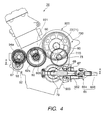
- Fig. 4 and Fig. 5 are drawings provided to explain the transmission mechanism of the transmission shown in Fig. 1 .
- Fig. 4 is a schematic side view of the principal part of the engine unit showing the positional relationship of each shift in the transmission mechanism.
- Fig. 5 is a sectional view of the A-A arrow part of Fig. 4 and shows the principal part of the engine unit provided with the transmission. In Fig. 5 , for the sake of convenience, the hatches indicating sections of component members are omitted.
- transmission mechanism 700 of transmission 7 is placed in an area that is adjacent to crankshaft accommodating section 921 in which crankshaft 60 is placed facing laterally in crank case 92 of engine unit 20 and includes mission case 770 formed along the longitudinal direction of crankshaft accommodating section 921.
- Mission case 770 is formed parallel to the direction in which crankshaft accommodating section 921 extends in crank case 92.
- Mission case 770 accommodates parts of first and second main shafts 71 and 72, drive shaft 73, and gears 81 through 86, 711, 712, 721, 722, 731, and 732.
- Mission case 770 forms engine unit chassis (drive unit case) 920 together with crankshaft accommodating section 921 and crank case 92.
- Clutch cover (side cover section) 770a, bell housing 930, clutch cover (side cover section) 770b, and propeller shaft case 66 are attached to this drive unit case 920.
- bell housing 930 and propeller shaft case 66 are shown hatched in Fig. 5 .
- Clutch cover 770a is attached detachably to one side surface (the right side surface) of mission case 770 in drive unit case 920, and covers first clutch 74 from one side (the right side).
- Bell housing 930 is attached detachably to mission case 770 from the other side (the left side surface) of mission case 770.
- Bell housing 930 has planar bell housing body 931 and transmission shaft accommodating section 933 formed integrally with bell housing body 931.
- Bell housing body 931 is attached to the other side (the left side surface) of mission case 770 and covers second main shaft 72 and drive shaft 73 in mission case 770 sideways.
- Transmission shaft accommodating section 933 is attached to mission case 770, thereby covering a connecting part of drive shaft 73 and transmission shaft 79 and rotatably accommodating transmission shaft 79.
- transmission shaft accommodating section 933 is detachably attached to the back end surface of mission case 770 covering drive shaft 73 in such a way as to surround the transmission shaft 79.
- transmission shaft accommodating section 933 The right side end surface of transmission shaft accommodating section 933 is open, and output gear (bevel gear) 793 fixed to an end (the left side end) of transmission shaft 79 via this opening meshes with bevel gear 651 of propeller shaft 65. Furthermore, this opening is covered by propeller shaft case 66 accommodating propeller shaft 65. In propeller shaft case 66, adjustable joint cover 67 that covers adjustable joint portion 654 (see Fig. 4 ) in propeller shaft 65 is installed consecutively.
- Clutch covers 770a and 770b are each formed in a bell shape, and cover first clutch 74 and second clutch 75 from both sides (the left and right sides) of crank case 92.
- one (right side) clutch cover 770a is attached detachably to one side surface (here, the right side surface) of mission case 770, and together with this one side surface, forms a clutch case that accommodates first clutch 74.
- Clutch cover 770b is provided detachably in the other side surface (the left side surface) of bell housing body 931 so as to cover bell housing body 931, and covers second clutch 75 from the other side (the left side).
- clutch cover 770b together with bell housing 930 attached detachably to the other side surface (the left side surface) of mission case 770, forms a clutch case (casing material) that accommodates second clutch 75.
- Transmission mechanism 700 of transmission 7 will now be described in detail.
- Starter motor 93 is attached to crank case 92 of drive unit case 920, and idler gear 97 and starter gear 96 are driven by this starter motor 93.
- Gear 94a is connected to starter gear 96 via one-way clutch section 95. This gear 94a meshes with gear 62a provided in crank web 62 of crankshaft 60. By this means, when starter motor 93 drives, gear 94a rotates integrally with starter gear 96 via one-way clutch section 95, and rotates crankshaft 60.
- Generator 94 is attached to crank case 92, and this generator 94 rotates integrally with gear 94a. As stated above, gear 94a is connected to gear 62a provided on crank web 62 of crankshaft 60. Thus, generator 94 is driven when crankshaft 60 rotates.
- crankshaft 60 of engine 6 ( Fig. 1 ) has a plurality of crank webs 61 and 62.
- crankshaft 60 is placed inside crankshaft accommodating section 921 of crank case 92 in such a way that the center part in the direction of extension is approximately in the center in the vehicle width direction.
- crank webs 61a and 61b placed at one end and the other end of crankshaft 60 are external gears on which gear grooves are formed on the outer periphery.
- These crank webs 61a and 61b are placed at positions facing the inside of both clutch cases (clutch covers 770a and 770b) from openings 92a and 92b that open on the first clutch 71 and second clutch 72 sides (here, rearward) on both sides (both sides axially) of crank case 92 in crankshaft accommodating section 921.
- crank web 61 a provided at one end (the right end) in crankshaft 60 meshes with first primary driven gear (also referred to as "first input gear") 40 in first clutch 74 inside crankshaft accommodating section 921.
- first primary driven gear also referred to as "first input gear”
- first clutch 74 inside crankshaft accommodating section 921.
- crank web 61b provided at the other end (the left end) in crankshaft 60 meshes with second primary driven gear (also referred to as "second input gear") 50 in second clutch 75 inside the clutch case.
- second primary driven gear also referred to as "second input gear”
- power transferred to second input gear 50 from crank web 61b at the other end of crankshaft 60 is transferred to second main shaft 72 from the other end of crankshaft 60.
- a meshing part between gear grooves of crank web 61b and second input gear 50 is placed in a communicating part that communicates inside the clutch case at the other end (the left end) of crankshaft accommodating section 921 in engine unit case 920.
- This communicating part is formed by means of opening 92b at the other end of crankshaft accommodating section 921 and throughhole 940 formed in a junction section of bell housing body 931 forming the clutch case.
- throughhole 940 is formed in a junction section between bell housing body 931 (partition member) and drive unit case 920 through the junction section.
- throughhole 940 there is formed a power transmitting part in which crank web 61b and second input gear 50 mesh with each other and which transfers rotation power from the crankshaft 60 side to second main shaft 72.
- First clutch 74 and second clutch 75 are placed rearward of crankshaft 60 (see Figs. 4 and 5 ), and opposite two ends 60a and 60b, respectively, of crankshaft 60 (see Figs. 2 and 5 ).
- Base end 71 a of first main shaft 71 is coupled to first clutch 74
- base end 72a of second main shaft 72 is coupled to second clutch 75.
- First clutch 74 and second clutch 75 will be described in detail later.
- First main shaft 71 and second main shaft 72 extend in mutually opposite directions from first clutch 74 and second clutch 75, and are placed in a direction (here, a lateral direction) intersecting the front-back direction of motorcycle 100 approximately at a right angle.
- First and second main shafts 71 and 72 are placed so as to position the end surface parts of mutually opposite front ends 71b and 72b approximately in the center in the vehicle width direction of motorcycle 100 in drive unit case 920 of the engine unit.
- first main shaft 71 and the front end (other end) 72b side of second main shaft 72 are inserted into hollow mission case 770 connected to crank case 92 of the engine unit.
- first main shaft 71 and second main shaft 72 are placed with the respective base end (one end) 71a/72a sides projecting left and right from both sides of mission case 770.
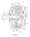
- Fig. 6 is a principal-part cross-sectional view showing first and second clutches 74 and 75 and first and second main shafts 71 and 72.
- first main shaft 71 front end 71 b and second main shaft 72 front end 72b are inserted into bearings 771 and 772 inside mission case 770, and are pivoted rotatably.
- These bearings 771 and 772 fit inside an opening in flange 773 that rises from the inner peripheral surface of mission case 770.
- Flange 773 rotatably supports the end surfaces of front ends 71b and 72b of first main shaft 71 and second main shaft 72 via bearings 771 and 772 so as to face each other in the center part of that flange 773.
- Front ends 71b and 72b of first main shaft 71 and second main shaft 72 are pivoted rotatably in crank case 92 by being inserted into bearings 771 and 772 inside flange 773 inside mission case 770, but this is not a limitation.
- a configuration will be assumed in which only one or other of front ends 71b and 72b of hollow first main shaft 71 and second main shaft 72 is received by a bearing inside a flange provided inside mission case 770.
- a configuration will be assumed in which a needle bearing is attached to the inner periphery of one or other of front ends 71b and 72b, and the other one of front ends 71b and 72b is inserted into this needle bearing.
- the other end of adjacent ends is inserted rotatably into one end in coaxially aligned first main shaft 71 and second main shaft 72, and the one end only is supported in flange 773 rising from that mission case 770 via a bearing.
- an end of one main shaft is inserted into an end of the other main shaft, and only that end of the one main shaft is supported rotatably inside mission case 770.
- both main shafts are made hollow and the respective hollow parts are made lubricating oil channels, lubricating oil can be made to flow satisfactorily inside both main shafts simply by providing an inflow of lubricating oil at an end at which the two main shafts overlap, or a point near that end.
- first main shaft 71 and second main shaft 72 have internal cavities 781 and 782, respectively, that extend in the axial direction and open at one end.
- cavity 781 opens at the front end of first main shaft 71
- cavity 782 opens at one end (here, the front end) of second main shaft 72.
- a plurality of throughholes 783 communicating between cavity 781 and the exterior of first main shaft 71 are formed in first main shaft 71
- a plurality of throughholes 784 communicating between cavity 782 and the exterior of second main shaft 72 are formed in second main shaft 72.
- Flange 773 placed inside mission case 770 has ring-shaped groove 774 in the center part in the axial direction in the inner peripheral surface of the opening, fitting inside bearings 771 and 772. Also, lubricating oil supply path 775 is formed in flange 773 so as to communicate with groove 774.
- Lubricating oil supply path 775 is connected to a lubricating oil supply source (not shown). With this kind of configuration, lubricating oil supplied to lubricating oil supply path 775 from the lubricating oil supply source is supplied to the space inside flange 773 from one end of lubricating oil supply path 775.
- Lubricating oil supplied inside flange 773 flows from one end of first main shaft 71 1 and one end of second main shaft 72, into cavity 781 and cavity 782.
- Lubricating oil that has flowed into cavity 781 is supplied to the interior of first clutch 74 and the outer periphery of first main shaft 71 via plurality of throughholes 783.
- lubricating oil that has flowed into cavity 782 is supplied to the interior of second clutch 75 and the outer periphery of second main shaft 72 via plurality of throughholes 784.
- a rise in temperature of second clutch 75 is prevented, and spline gear 722, sixth gear 86, and fixed gear 721 are lubricated.
- first clutch 74 and second clutch 75 are placed at ends (base ends) 71a and 72a on the sides farthest from each other in a lateral direction.
- first and second clutches 74 and 75 are connected outwardly from the axis to base end (one end) 71 a and base end (one end) 72a of first and second main shafts 71 and 72 projecting axially outward from both side surfaces of mission case 770, as shown in Fig. 5 and Fig. 6 .
- Base end 72a of second main shaft 72 projects farther axially outward than the other side surface of mission case 770 and bell housing body 931 attached detachably to the other side surface, and is positioned farther axially outward than the same-side (left-side) end of adjacent drive shaft 73, as shown in Fig. 5 .
- First clutch 74 is placed farther axially outward than one side surface of mission case 770, and is covered by clutch cover 770a attached detachably to one side surface (one side surface in a direction approximately perpendicular to the horizontal with respect to the vehicle center axis)
- Second clutch 75 is placed farther axially outward than the other side surface of mission case 770 and bell housing body 931 attached detachably to the other side surface, and is covered, axially from the outside, by clutch cover 770b.
- Second clutch 75 is connected detachably to base end 72a of second main shaft 72 at a position overlapping part of middle gear 76 axially sideways (on the left side) of drive shaft 73.
- bell housing body 931 partition member
- the clutch case that is formed by clutch cover 770b and bell housing body 931 and accommodates second clutch 75 and an accommodating area of drive shaft 73 to which middle gear 76 is fixed are separated by bell housing body 931.
- Transmission shaft 79 is placed rotatably in transmission shaft accommodating section 933 that opens at the left end via bearing areas 795, 796.
- the left end of transmission shaft 79 protruding from the left end of transmission shaft accommodating section 933 is placed in propeller shaft case 66.
- Output gear 793 provided at the left end of transmission shaft 79 meshes with bevel gear 651 fixed to first shaft 652 of propeller shaft 65 in propeller shaft case 66.
- Output gear 793 is placed in a position aligned with second clutch 75 and is placed in a position in the close vicinity of the clutch case of second clutch 75 when propeller shaft case 66, together with propeller shaft 65, is removed from mission case 770.
- First shaft 652 is placed in propeller shaft case 66 facing the front-back direction of the vehicle, and an end thereof on the front side of the vehicle is attached rotatably via bearing 661. Furthermore, an end of first shaft 652 on the rear side of the vehicle protrudes from propeller shaft case 66 to the rear of the vehicle via bearing 662, bearing keep 663 and oil seal 663.
- This protruding part is coupled to second shaft 656 inside adjustable joint cover 67 via adjustable joint section(see Fig. 4 ) 654.
- Second shaft 656 is provided with bevel gear 653 (see Fig. 3 ) that meshes with driven gear 13 on the rear wheel 12 side. With this configuration, in a direction perpendicular to transmission shaft 79, power is taken out from the engine and transmitted to rear wheel 12, In Fig. 5 , adjustable joint section 654 (see Fig. 4 ) and second shaft 656 (see Fig. 4 ) are omitted.
- First and second clutches 74, 75 shown in Fig. 2 through Fig. 6 are of the same configuration and use the same multi-plate type clutch.
- first clutch 74 As shown in Fig. 6 , first pressure plate 7421 of pressure plate 742 is biased toward first input gear 40 by clutch spring 743. As a result, a state normally exists in which plurality of clutch plates 741 and plurality of friction plates 744 are in mutual contact, and the torque of crankshaft 60 (see Fig. 2 ) is transferred to first main shaft 71 via first input gear 40, clutch housing 740, and center hub 745.
- first pressure plate 7521 of pressure plate 752 is biased toward second input gear 50 by clutch spring 753.
- clutch spring 753 As a result, a state normally exists in which plurality of clutch plates 751 and plurality of friction plates 754 are in mutual contact, and the torque of crankshaft 60 (see Fig. 2 ) is transferred to second main shaft 72 via second input gear 50, clutch housing 750, and center hub 755.
- first clutch actuator 77 is coupled to first clutch 74 via first pullrod 70.
- second clutch actuator 78 is coupled to second clutch 75 via second pullrod 80.
- First pullrod 70 is coupled to pressure plate 742 of first clutch 74 (see Fig. 5 and Fig. 6 ), and second pullrod 80 is coupled to pressure plate 752 of second clutch 75 (see Fig. 5 and Fig. 6 ).
- First clutch actuator 77 shown in Fig. 2 has, for example, a link (not shown) that pulls first pullrod 70 toward the first clutch actuator 77 side, a hydraulic cylinder (not shown) that operates the link, a motor (not shown) for generating hydraulic pressure in the hydraulic cylinder, and so forth.
- Second clutch actuator 78 has the same kind of configuration as first clutch actuator 77.
- first pressure plate 7421 in pressure plate 742 (see Fig. 5 and Fig. 6 ) is pulled toward first clutch actuator 77 due to the fact that first pullrod 70 is pulled toward first clutch actuator 77 by first clutch actuator 77.
- plurality of clutch plates 741 and plurality of friction plates 744 are separated from each other, and the transfer of torque from first input gear 40 to first main shaft 71 is disconnected.
- first pressure plate 7521 of pressure plate 752 (see Fig. 5 and Fig. 6 ) is pulled toward second clutch actuator 78 due to the fact that second pullrod 80 is pulled toward second clutch actuator 78 by second clutch actuator 78.
- plurality of clutch plates 751 and plurality of friction plates 754 are separated from each other, and the transfer of torque from second input gear 50 to second main shaft 72 is disconnected.
- first and second clutches 74 and 75 come to a state in which crankshaft 60 is connected to first main shaft 71 and second main shaft 72, respectively, that is, torque is transferred to first main shaft 71 and second main shaft 72.
- first clutch actuator 77 and second clutch actuator 78 are driven, first clutch 74 and second clutch 75 come to a state in which torque to first main shaft 71 and second main shaft 72 is disconnected.
- first and second clutches 74 and 75 each have a back torque limiter that limits the application of torque in first and second main shafts 71 and 72 in a direction opposite to the forward direction (the direction in which the engine drives so as to accelerate the vehicle) that is the direction in which rotation is performed in accordance with the rotation of crankshaft 60 by engine drive.
- first clutch 74 is comprising a back torque limiter that limits back torque applied to first main shaft 71
- second clutch 75 is comprising a back torque limiter that limits back torque applied to second main shaft 72.
- First clutch 74 and second clutch 75 are a multi-plate clutch configured in the same way and hence have the same basic configuration of the same mirror-symmetric structure.
- second clutch 75 is also comprising a back torque limiter having the same basic configuration as that of first clutch 74, but with a mirror-symmetric structure. Therefore, only the configuration of first clutch 74 is described below, and a description of the configuration of second clutch 75 is omitted.
- Fig. 7 is a drawing showing a state in which clutch spring 743 and pressure plate 742 have been removed from first clutch 74 in transmission 7 shown in Fig. 5 , viewed from the right side
- Fig. 8 is a partial cross-sectional view through line E-F-G of the first clutch shown in Fig. 7
- Fig. 9 is an exploded perspective view showing the principal-part configuration of the first clutch shown in Fig. 8 .
- first clutch 74 shown in Fig. 8 a principal-part cross-section is shown of different parts above and below rotation center m.
- first input gear 40 that transfers torque of crankshaft 60 to first clutch 74 is fitted over externally fitted collar 40a and needle bearing 40b fitted around collar 40a, on other end (base end) 71a of first main shaft 71.
- first input gear 40 becomes rotatable on first main shaft 71.
- clutch housing 740 is provided integrally so as to be rotatable together with first input gear 40.
- Clutch housing 740 has a bottomed cylindrical shape, and is attached integrally to a hub part of input gear 40 fitted externally in a rotatable fashion on an end (base end 71a) of first main shaft 71, with first main shaft 71 inserted through the center of that bottom part and the inside opened at one end.
- clutch housing 740 is rotatably attached coaxially with first main shaft 71 together with first input gear 40 to the outer periphery of an end (base end 71a) of first main shaft 71 together with first input gear 40.
- annular friction plate 744 and annular clutch plate 741 placed alternately and mutually separably in the axial direction, center hub 745 placed inside friction plates 744 and clutch plates 741, and second pressure plate 7422 sandwiching friction plates 744 and clutch plates 741 together with first pressure plate 7421.
- Center hub 745 and second pressure plate 7422 form a clutch hub section placed inside clutch housing 740.
- Annular friction plates 744 are placed so as to be coaxial with first main shaft 71, and outer diameter splines formed on the outer periphery are meshed with inner diameter splines formed on the inner peripheral surface of clutch housing 740. By this means, friction plates 744 become rotatable about the axial center of first main shaft 71 together with clutch housing 740.
- the plurality of annular clutch plates 741 placed between these friction plates 744 are meshed with center hub 745 placed inside plurality of clutch plates 741 via the inner diameter splines formed on the inner periphery. By this means, clutch plates 741 rotate together with center hub 745.
- center hub 745 is placed, separably in the axial direction, adjacent to second pressure plate 7422 attached in a flange shape extending radially outward from first main shaft 71 projecting inside clutch housing 740.
- Stepped nut (muffler) 747 is attached to an end (to be specific, the base end) of this first main shaft 71 via externally fitted leaf spring 746.
- This stepped nut 747 fixes second pressure plate 7422 to an end of first main shaft 71 and prevents its detachment from that first main shaft 71, and also inhibits movement of leaf spring 746 in the axial direction.
- Center hub 745 is placed so as to surround an end of first main shaft 7 1 , and is formed in a bottomed cylindrical shape by cylindrical section 7451 on which outer diameter splines are formed that mesh with inner diameter splines of clutch plates 741 on the outer peripheral surface, and boss section 7452 of a disk shape, placed on press boss section 7426 of second pressure plate 7422.
- cylindrical section 7451 is comprising an attachment piece having a rivet hole (not shown) that extends inside the inner wall on one opening side, and boss section 7452 is attached to the back surface of this attachment piece.
- Cylindrical section 7451 shown in Fig. 8 is connected movably in the axial direction in a state in which movement in the rotation direction is regulated by being mortised to first pressure plate 7421 at the open end edge of one end.
- outer diameter splines 7451a formed on the outer peripheral surface on the open end edge of cylindrical section 7451 mesh with inner diameter splines 7421c formed along the axial direction of annular projection 7421b projecting toward second pressure plate 7422 from the outer periphery of body 7421a of first pressure plate 7421, so that movement in the circumferential direction is regulated, and movement in the axial direction is not restricted.
- this cylindrical section 7451 is closed by boss section 7452, and this boss section 7452 is biased toward second pressure plate 7422 by leaf spring 746 from one end of first main shaft 71.
- Leaf spring 746 is fixed by stepped nut 747 attached to first main shaft 71 projecting and passing through press boss section 7426 of second pressure plate 7422 inside center hub 745. Inside clutch housing 740, leaf spring 746 presses boss section 7452 (center hub 745) placed separably in the axial direction with respect to second pressure plate 7422 toward second pressure plate 7422 from the stepped nut 747 side.
- Boss section 7452 has elongated hole 7453 through which stud 7423 rising from second pressure plate 7422 in the axial direction passes movably in the circumferential direction, and convex follower cam 7454 that engages with concave operating cam 7424 formed on second pressure plate 7422 disengageably about the axis.
- a plurality of these elongated holes 7453 and follower cams 7454 are placed at predetermined intervals in the circumferential direction of boss section 7452.
- This boss section 7452 is rotatably fitted over press boss hub section 7426b of press boss section 7426 of second pressure plate 7422 attached to an end of first main shaft 71. Also, follower cam 7454 of boss section 7452 in center hub 745 is in an engaged state placed inside operating cam 7424 of press boss section 7426. With boss section 7452 in this state, stud 7423 rising from outer periphery 7426a (see Fig. 9 ) is inserted into an elongated hole so as to be movable by a predetermined distance in the circumferential direction.
- follower cam 7454 is provided on the surface opposite press boss section 7426 of second pressure plate 7422 (for convenience, referred to as the "opposing surface"), projecting toward the press boss section 7426 side.
- Follower cam 7454 is formed on boss section 7452 so as to engage in the rotation direction with the opposing surface abutting operating cam 7424 when rotating in one direction about the axis, and to rotate with the opposing surface separated from operating cam 7424 when rotating in the other direction.
- Fig. 10 is a drawing showing boss section 7452 of center hub 745 comprising follower cam 7454 in first clutch 74, in which Fig. 10A is a drawing of the same boss section 7452 viewed from the opposing surface -- that is, from one end of first main shaft 71 (the right side of the vehicle) -- and Fig. 10B is a partial cross-sectional view through R-R line in Fig. 10A .
- follower cam 7454 is formed projecting from opposing surface 7452a of boss section 7452 suspended inside cylindrical section 7451 in center hub 745.
- follower cam 7454 has contact end surface 7454a on the counterclockwise direction side that makes surface contact with operating cam 7424 when output to the rear wheel, which is the driving wheel, by rotation in a counterclockwise direction when viewing the vehicle from the right side, and inclined surface 7454b that is inclined toward the clockwise direction side from the projecting end of contact end surface 7454a.
- follower cam 7454 is formed in a right-angled trapezium longitudinal shape, with contact end surface 7454a rising perpendicularly with respect to opposing surface 7452a, and having inclined surface 7454b inclined toward the opposing surface 7452a side from the periphery of the projection of that contact end surface 7454a.
- boss section 7452 of center hub 745 elongated holes 7453, and rivet holes 7452b joined via rivets to rivet holes (not shown) of an attachment piece extending inward from the inner wall of cylindrical section 7451 (see Fig. 8 ), are formed at predetermined intervals around the central opening.
- operating cam (helical cam) 7424 is formed in a concave shape on the opposing surface of press boss section 7426 facing boss section 7452 of center hub 745 on second pressure plate 7422.
- Press boss section 7426 is disk-shaped, and forms second pressure plate 7422 by means of annular flange 7427 attached around the periphery, and a plurality of studs 7423 attached so as to rise from the top of the opposing surface (see Fig. 8 and Fig. 9 ).
- Fig. 11 is a drawing showing press boss section 7426 of second pressure plate 7422 in first clutch 74, in which Fig. 11A is a front view of press boss section 7426 from the opposing surface side -- that is, one end of first main shaft 71 (the right side of the vehicle) -- and Fig. 11B is a partial cross-sectional view through line S-S in Fig. 11A .
- Press boss section 7426 shown in Fig. 11 is disk-shaped, and is joined by means of spline coupling to base end 71a of first main shaft 71 inserted into an opening formed in the center, and rotates integrally and coaxially with first main shaft 71.
- Press boss section 7426 has press boss hub section 7426b projecting toward the boss section 7452 side in the center part around the opening in which first main shaft 71 is inserted in disk-shaped outer periphery 7426a having an opposing surface facing boss section 7452 of center hub 745.
- Boss section 7452 of center hub 745 is fitted over this press boss hub section 7426b so as to be movable in the axial direction and in the circumferential direction, and is placed overlapping press boss section 7426 in the axial direction.
- convex follower cam 7454 provided on boss section 7452 of center hub 745 fits disengageably inside concave operating cam 7424 formed on the opposing surface of outer periphery 7426a on press boss section 7426.
- Operating cam 7424 corresponds to the shape of follower cam 7454 from the opposing surface, and is formed in a concave shape having vertical end surface 7424a parallel to the axial direction and perpendicular to the opposing surface, and inclined surface 7424b that is inclined in the circumferential direction.
- Operating cam 7424 on second pressure plate 7422 and follower cam 7454 on center hub 745 are formed so as to engage by rotating in one direction around the axis about the axial center of first main shaft 71, and to disengage through rotation in the other direction around the axis.
- operating cam 7424 and follower cam 7454 have inclined surfaces 7424b and 7454b that slide against each other formed as surfaces inclined helically about the axial center.
- the other direction around the axis means the opposite direction to the forward torque direction in which torque is transferred from crankshaft 60 via first clutch 74 and drives the rear wheel. Therefore, “the other direction around the axis” in first clutch 74 here is a clockwise direction, opposite to the counterclockwise direction in which forward torque is transferred to drive shaft 73 as viewed from the right side of the vehicle through rotation of first main shaft 71.
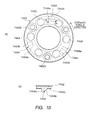
- boss section 7552 of center hub 755 shown in Fig. 12 and press boss section 7526 of the second pressure plate shown in Fig. 13 fit rotatably about the base end 72a side of second main shaft 72.
- convex follower cam 7554 and concave operating cam 7524 are formed on opposing surfaces of boss section 7552 shown in Fig. 12 and press boss section 7526 shown in Fig. 13 , so that, rotating relatively about the axial center of second main shaft 72, the respective opposing surfaces engage with each other in one direction around the axis (the clockwise direction), and disengage from each other in the other direction around the axis (the counterclockwise direction), as viewed from the left side of the vehicle.
- operating cam 7524 and follower cam 7554 have contact end surfaces 7524a and 7554a that are placed on a flat surface passing through the axial center at the clockwise-side end as viewed from the left side of the vehicle, and make surface contact and engage with each other when rotating relatively.
- operating cam 7524 and follower cam 7554 have inclined surfaces 7524b and 7554b that are connected to an end in the counterclockwise direction are inclined helically about the axial center, and through the sliding against each other of these inclined surfaces 7524b and 7554b, boss section 7552 is distanced from press boss section 7526 in the axial direction.
- Fig. 14 is a schematic diagram showing the relationship between an operating cam of a press boss section and a follower cam of a boss section as viewed from the axial center side.
- a description will be given using an operating cam of a press boss section and a follower cam of a boss section in the first clutch.
- clutch 74 boss section 7452 of center hub 745 rotates in one direction that is the Z direction in which torque is applied (the counterclockwise direction of the main shaft as viewed from the right side of the vehicle).
- press boss section 7426 is pressed in the Z direction via follower cam 7454 and operating cam 7424, moves in that direction, and rotates first main shaft 71 in the Z direction.
- Power is taken from the base end of crankshaft 60 via first clutch 74 and second clutch 75 configured in this way, is transferred selectively to first main shaft 71 and second main shaft 72, and is output to rear wheel 12 (see Fig. 1 ) via drive shaft 73, transmission shaft 79, and propeller shaft 65.
- Fig. 15 is a drawing provided to explain a back torque limiting operation in the engine unit according to the present invention, being a schematic diagram showing an axis arrangement of a crankshaft, main shaft, and drive shaft in a transmission mounted in a vehicle, viewed from the right side of the vehicle.
- crankshaft 60 rotates clockwise (“CW") and main shafts (first main shafts 71 and 72) rotate counterclockwise (“CCW”) as indicated by the arrow Z direction and drive shaft 73 rotates clockwise (CW) as indicated by the arrow X as shown in Fig. 15 .
- crankshaft 60 rotates clockwise (in the X direction)
- the main shaft rotates in the Z direction
- drive shaft 73 rotates in the X direction.
- crankshaft 60 rotating in CW direction X through engine drive is input to clutch housing 740 via first input gear 40, and clutch housing 740 rotates in CCW direction Z about the axial center of first main shaft 71.
- friction plates 744 meshed with inner diameter splines of clutch housing 740 also rotate integrally. Between friction plates 744 are sandwiched a plurality of clutch plates 741 meshed with the outer diameter of center hub 745 by means of inner diameter splines.
- first pressure plate 7421 is pressed toward second pressure plate 7422 by the force by which clutch spring 743 tries to extend. Consequently, through this pressure, friction plates 744 and clutch plates 741 are pressed toward second pressure plate 7422, pressure operates mutually between friction plates 744 and clutch plates 741, and frictional force is generated.
- torque from crankshaft 60 is transferred to center hub 745, with torque (that is, a clutch transfer torque capacity) of a magnitude obtained by multiplication of frictional force generated between friction plates 744 and clutch plates 741 and the effective contact perimeter between friction plates 744 and clutch plates 741 (that is, the distance from the approximate center of the contact width to the center of first main shaft 71), as an upper limit.
- torque that is, a clutch transfer torque capacity
- Cam concavities and convexities are combined on second pressure plate 7422, and center hub 745 is fitted thereto so as to be movable in the axial direction by means of engagement and disengagement thereof.
- back torque limiter cams here, concave operating cam 7424 and convex follower cam 7454
- concave operating cam 7424 and convex follower cam 7454 provided on the respective opposing surfaces of boss section 7452 of center hub 745 and press boss section 7426 on second pressure plate 7422 each have one surface formed as a surface approximately parallel to the center axis of first main shaft 71, and the other surface formed as an approximately helical surface.
- these "one surfaces” are formed on the drive direction Z end of first main shaft 71, and the “other surfaces” are formed so as to incline toward the reverse Z direction side from the "one surface” side.
- reverse torque is a torque applied in a direction reverse to forward torque and means such torque that makes torque input from engine 6 (see Fig. 1 ) to clutch housing 740, friction plates 744, clutch plates 741, and center hub 745 via first input gear 40 be in a deceleration direction (the opposite direction to that indicated by arrow Z).
- Reverse torque is generated when, in the configuration of the engine unit that takes power from both ends of crankshaft 60 placed horizontally to left and right, left and right clutches 71 and 72 are both connected while power transfer gears on both the left and right are meshed enabling transfer of power in a shift change or the like, and torque is applied to both clutches.
- control is performed by ECU 10 so that a shift change is performed instantaneously by switching from one clutch to the other, and therefore there are no effects due to reverse torque.
- torque in the reverse of the rotation direction may be applied to one clutch taking power from one of the both ends of crankshaft 60, via crankshaft 60 and drive shaft 73, from the power transfer having the other clutch (for example, second clutch 75 for first clutch 74).
- press boss section 7426 of second pressure plate 7422 and boss section 7452 of center hub 745 move so as to become distanced from each other on the axis line of first main shaft 71 (see Fig. 14 ).
- boss section 7452 of center hub 745 having follower cam 7454 rotates about first main shaft 71 and moves toward first pressure plate 7421 in the axial direction of first main shaft 71.
- Boss section 7452 of center hub 745 is biased in a direction in which a projection (convexity) of follower cam 7454 is accommodated by a depression (concavity) of operating cam (helical cam) 7424 by leaf spring 746 via nut 747.
- center hub 745 continues rotating in the R direction from operating cam (helical cam) 7424 and swells until the R direction component (see Fig. 8 ) of resistance arising at the other surface (helical cam surface) due to reverse torque, and the pressing force of leaf spring 746, are in balance.
- crankshaft 60 that is, engine 6 (see Fig. 1 )from drive shaft 73 via first main shaft 71, press boss section 7426 of second pressure plate 7422, and the helical cam surfaces of operating cam 7424 and follower cam 7454, and via center hub 745, clutch plates 741, friction plates 744, clutch housing 740, and first input gear 40.
- center hub 745 when reverse torque further increases, and the end surface (the opening-side end surface of the cylindrical section) of center hub 745 reaches first pressure plate 7421, center hub 745 continues rotating and swells the helical cam surface in the R direction up to a position at which the R direction component of resistance arising at the helical cam surface due to reverse torque, and the resultant force of pressing force of clutch spring 743 added to the bias of leaf spring 746, are in balance.
- clutch 74 continues reverse torque transfer within a range in which the magnitude of the reverse torque is less than the transfer torque capacity of the clutch for which the pressing force of clutch spring 743 has been reduced.
- friction plates 744 and clutch plates 741 rotate relatively -- that is, the clutch slips and reverse torque transfer is limited.
- the clutch transfer torque capacity with respect to reverse torque attains its upper limit while the clutch is slipping, and greater reverse torque than that is not transferred.
- the transfer torque capacity with respect to reverse torque can be limited by the operation of a back torque limiter whereby first pressure plate 7421 and clutch plates 741 slip with respect to friction plates 744.
- center hub 745 moves toward the second pressure plate 7422, the reduced pressing force due to clutch spring 743 is restored, and the transfer torque capacity of first clutch 74 recovers.
- mutual boss section cam surfaces 7454b and 7424b or 7454a and 7424a engage, and a state in which torque is transferred by these engaging surfaces is restored.
- gears 711, 721, 85, 86, 712, and 722 that mesh with gears 81, 82, 731, 732, 83, and 84 of drive shaft 73 are placed on first main shaft 71 and second main shaft 72 respectively.
- first main shaft 71 the following gears are arranged on first main shaft 71 in order from the base end to which first clutch 74 is connected: fixed gear (also referred to as “first-equivalent gear”) 711, fifth gear 85, and spline gear (also referred to as “third-equivalent gear”) 712.
- Fixed gear 711 is formed integrally with first main shaft 71, and rotates together with first main shaft 71. Fixed gear 711 meshes with first gear 81 of drive shaft 73, and therefore is also referred to as "first-equivalent gear.”
- Fifth gear 85 is attached to first main shaft 71, so as to be rotatable about the axis of first main shaft 71 and with its movement regulated in the axial direction, at a position between and at a distance from first-gear fixed gear 711 and third-gear spline gear 712.
- Fifth gear 85 meshes with spline gear 731(also referred to as "fifth-equivalent gear") of drive shaft 73.
- Spline gear 712 is attached to first main shaft 71 at the front end of first main shaft 71 -- that is, at the distant end from first clutch 74 -- so as to be movable in the axial direction, and rotates together with the rotation of first main shaft 71.
- spline gear 712 is attached to first main shaft 71, so as to be able to slide in the axial direction while its rotation is regulated, by means of splines formed along the axial direction on the outer periphery of the front end of first main shaft 71, and meshes with third gear 83 of drive shaft 73.
- This spline gear 712 is coupled to shift fork 142, and moves on first main shaft 71 in the axial direction through movement of shift fork 142.
- Spline gear 712 is also referred to here as "third-equivalent gear.”
- Spline gear 712 moves toward fifth gear 85 on first main shaft 71 and engages with fifth gear 85, and regulates rotation (idling) about the axis of fifth gear 85 on first main shaft 71.
- fifth gear 85 is fixed to first main shaft 71, and is made integrally rotatable together with the rotation of first main shaft 71.
- second main shaft 72 the following gears are arranged on second main shaft 72 in order from the base end to which second clutch 75 is connected: fixed gear (also referred to as “second-equivalent gear”) 721, sixth gear 86, and spline gear (also referred to as “fourth-equivalent gear”) 722.
- Fixed gear 721 is formed integrally with second main shaft 72, and rotates together with second main shaft 72. Fixed gear 721 meshes with second gear 82 of drive shaft 73, and therefore is also referred to as "second-equivalent gear.”
- Sixth gear 86 is attached to second main shaft 72, so as to be rotatable about the axis of second main shaft 72 and with its movement regulated in the axial direction, at a position between and at a distance from second-gear fixed gear 721 and fourth-gear spline gear 722.
- This sixth gear 86 meshes with spline gear 732 (also referred to as "sixth-equivalent gear") of drive shaft 73.
- Spline gear (fourth-equivalent gear) 722 is attached to second main shaft 72 at the front end of second main shaft 72that is, at the distant end from second clutch 75 -- so as to be movable in the axial direction, and rotates together with the rotation of second main shaft 72.
- spline gear 722 is attached to second main shaft 72, so as to be able to slide in the axial direction while its rotation with respect to second main shaft 72 is regulated, by means of splines formed along the axial direction on the outer periphery of the front end of second main shaft 72, and meshes with fourth gear 84 of drive shaft 73.
- This spline gear 722 is coupled to shift fork 143, and moves on second main shaft 72 in the axial direction through movement of shift fork 143.
- Spline gear 722 moves toward sixth gear 86 on second main shaft 72 and engages with sixth gear 86, and regulates turning (idling) about the axis of sixth gear 86 on second main shaft 72.
- sixth gear 86 is fixed to second main shaft 72, and is made integrally rotatable together with the rotation of second main shaft 72.
- first gear 81 spline gear (fifth-equivalent gear) 731
- third gear 83 fourth gear 84
- spline gear (sixth-equivalent gear) 732 second gear 82
- middle gear 76 spline gear (sixth-equivalent gear)
- first gear 81, third gear 83, fourth gear 84, and second gear 82 are provided rotatably about drive shaft 73 in a state in which their movement in the axial direction of drive shaft 73 is inhibited.
- Spline gear (fifth-equivalent gear) 731 is attached to drive shaft 73 so as to be able to slide in the axial direction while its rotation is regulated by means of spline engagement. That is to say, spline gear 731 is attached so as to be movable in a sliding direction with respect to drive shaft 73, and also rotates together with drive shaft 73. This spline gear 731 is coupled to shift fork 141 of shift mechanism 701, and moves on drive shaft 73 in the axial direction through the movement of shift fork 141.
- Spline gear (sixth-equivalent gear) 732 is attached to drive shaft 73 so as to be able to slide in the axial direction while its turning is regulated by means of spline engagement. That is to say, spline gear (sixth-equivalent gear) 732 is attached so as to be movable in a sliding direction with respect to drive shaft 73, and also rotates together with drive shaft 73. This spline gear 732 is coupled to shift fork 144 of shift mechanism 701, and moves on drive shaft 73 in the axial direction through the movement of shift fork 144.
- spline gears 712, 722, 731, and 732 function as transmission gears, and also function as dog selectors.
- Spline gears 712, 722, 731, and 732 are coupled by means of a dog mechanism to respective transmission gears (first gear 81 through sixth gear 86) that are adjacent in the axial direction by moving in the axial direction. That is to say, mutually fitting concave and convex parts are formed on mutually opposing surfaces of spline gears 712, 722, 731, and 732 and transmission gears adjacent in the axial direction, and both gears rotate integrally through the fitting together of the concave and convex sections.
- spline gear (third-equivalent gear) 712 on first main shaft 71 is distanced from fifth gear 85, and meshes with third gear 83 on drive shaft 73.
- spline gear (fifth-equivalent gear) 731 on drive shaft 73 moves toward first gear 81 and is distanced from third gear 83, and fits together and coupled with first gear 81.
- first gear 81 is placed in a state in which it is fixed integrally to drive shaft 73 via spline gear 731.
- third gear 83 meshing with spline gear 712 of first main shaft 71 and fifth gear 85 meshing with spline gear 731 of drive shaft 73 enter a state in which they idle about the respective axes.
- spline gear (fourth-equivalent gear) 722 on second main shaft 72 is distanced from sixth gear 86, and meshes with fourth gear 84 on drive shaft 73.
- spline gear (sixth-equivalent gear) 732 on drive shaft 73 moves toward second gear 82 and is distanced from fourth gear 84, and fits together and coupled with second gear 82.
- second gear 82 is placed in a state in which it is fixed integrally to drive shaft 73 via spline gear 732.
- fourth gear 84 meshing with spline gear 722 of second main shaft 72 and sixth gear 86 meshing with spline gear 732 of drive shaft 73 enter a state in which they idle about the respective axes.
- spline gear (third-equivalent gear) 712 on first main shaft 71 is distanced from fifth gear 85, and meshes with third gear 83 on drive shaft 73.
- spline gear (fifth-equivalent gear) 731 on drive shaft 73 moves toward third gear 83 and is distanced from first gear 81, and fits together and is coupled with third gear 83.
- third gear 83 is placed in a state in which it is fixed integrally to drive shaft 73 via spline gear 731.
- first gear 81 meshing with fixed gear 711 of first main shaft 71 and fifth gear 85 meshing with spline gear 731 of drive shaft 73 enter a state in which they idle about the respective axes.
- spline gear (fourth-equivalent gear) 722 on second main shaft 72 is distanced from sixth gear 86, and meshes with fourth gear 84 on drive shaft 73.
- spline gear (sixth-equivalent gear) 732 on drive shaft 73 moves toward fourth gear 84 and is distanced from second gear 82, and fits together and is coupled with fourth gear 84.
- fourth gear 84 is placed in a state in which it is fixed integrally to drive shaft 73 via spline gear 732.
- second gear 82 meshing with fixed gear 721 of second main shaft 72 and sixth gear 86 meshing with spline gear 732 of drive shaft 73 enter a state in which they idle about the respective axes.
- spline gear (third-equivalent gear) 712 on first main shaft 71 moves toward fifth gear 85 and is coupled by fitting together with fifth gear 85, and that fifth gear 85 is placed in a state in which it is fixed integrally to the first main shaft via spline gear 712.
- spline gear (fifth-equivalent gear) 731 on drive shaft 73 is distanced from both first gear 81 and third gear 83, and meshes with fifth gear 85 at a position at which it is not coupled to either.
- first gear 81 and third gear 83 on drive shaft 73 meshing with fixed gear 711 and spline gear 712 of first main shaft 71 enter a state in which they idle about the axis of drive shaft 73.
- spline gear (fourth-equivalent gear) 722 on second main shaft 72 moves toward sixth gear 86 and is coupled by fitting together with sixth gear 86, and that sixth gear 86 is placed in a state in which it is fixed integrally to second main shaft 72 via spline gear 722.
- spline gear 732 on drive shaft 73 is distanced from both second gear 82 and fourth gear 84, and meshes with sixth gear 86 at a position at which it is not coupled to either.
- second gear 82 and fourth gear 84 on drive shaft 73 meshing with fixed gear 721 and spline gear 722 of second main shaft 72 enter a state in which they idle about the axis of drive shaft 73.
- gear shifting is performed in transmission 7 by having spline gears 712, 722, 731, and 732 of transmission mechanism 700 moved as appropriate in the axial direction by means of shift forks 141 through 144.
- shift mechanism 701 that performs gear shifting by moving spline gears 712, 722, 731, and 732 of transmission mechanism 700 in the axial direction via shift forks 141 through 144 in transmission 7.
- Shift mechanism 701 shown in Fig. 2 has elongated shift forks 141 through 144 coupled to spline gears 731, 712, 722, and 732 at the front end, cylindrical shift cam 14 that has its rotation axis placed parallel to first and second main shafts 71 and 72 and drive shaft 73, and moves shift forks 141 through 144 in the axial direction of that rotation axis by rotating, shift cam drive unit 800 that provides rotational driving of shift cam 14, motor 8, and transmission mechanism 41 that couples motor 8 to shift cam drive unit 800 and transfers the driving force of motor 8.
- Shift forks 141 through 144 are installed between spline gears 731, 712, 722, and 732 and shift cam 14, and are placed distanced from each other in the axial direction of first and second main shafts 71 and 72, drive shaft 73, and shift cam 14. These shift forks 141 through 144 are arranged so as to be parallel to each other, and are each placed movably in the axial direction of the rotation axis of shift cam 14.
- Shift forks 141 through 144 have pin sections at the base end, placed so as to be movable respectively within four cam grooves 14a through 14d formed in the outer periphery of shift cam 14. That is to say, shift forks 141 through 144 are follower members of shift cam 14, which is the driving source, and slide in the axial direction of first and second main shafts 71 and 72 and drive shaft 73 in accordance with the shape of cam grooves 14a through 14d of shift cam 14. By means of this sliding movement, spline gears 731, 712, 722, and 732 coupled to the front end each move in the axial direction on shafts passing through the respective inner diameters.
- Shift cam 14 is rotated by the driving force of motor 8 transferred to shift cam drive unit 800 via drive mechanism 41, and through this rotation, at least one of shift forks 141 through 144 is moved in accordance with the shape of cam grooves 14a through 14d.
- shift forks 141 through 144 that move in response to the rotation of shift cam 14 having cam grooves 14a through 14d, a spline gear coupled to a moved shift fork moves, and a gear shift of transmission 7 (transmission mechanism 700) is performed.
- shift signal a signal indicating that fact
- ECU 10 controls first and second clutch actuators 77 and 78 and motor 8.
- first clutch 74 or second clutch 75, or both first and second clutches 74 and 75 is/are disengaged, shift cam 14 rotates, and a gear shift in transmission 7 (transmission mechanism 700) is performed.
- Fig. 16 is a side view showing a state in which clutch cover 770b covering second clutch 74, second clutch 74, and bell housing 930 are removed in a vehicle comprising engine unit 20 according to one embodiment of the present invention.
- second clutch 75 can be exposed on one side of the vehicle simply by removing clutch cover 770b covering second clutch 75 on the axially outward other side (the left side).
- second clutch 75 maintenance can be performed easily without removing the engine unit from the frame by removing clutch cover 770b, which is part of the clutch case accommodating second clutch 75, even after the engine unit has been mounted on the vehicle.
- second clutch 75 also for first clutch 74, maintenance can be performed with first clutch 74 exposed simply by removing clutch cover 770a.
- propeller shaft case 66 can be attached on the lateral side (the left side) of the vehicle and propeller shaft 65 can be installed.
- Transmission 7 of this embodiment is comprising first clutch 74 that inputs rotation power transferred from crankshaft 60 to first main shaft 71 and outputs driving force to the driving wheel side via an odd-numbered transmission gear mechanism (gears 81, 83, 85, 711, 712, and 731) set as odd-numbered transmission gears, and second clutch 75 that inputs rotation power transferred from crankshaft 60 to second main shaft 72 and outputs driving force to rear wheel 12 via an even-numbered transmission gear mechanism (gears 82, 84, 86, 721, 722, and 732) set as even-numbered transmission gears.
- first clutch 74 that inputs rotation power transferred from crankshaft 60 to first main shaft 71 and outputs driving force to the driving wheel side via an odd-numbered transmission gear mechanism (gears 81, 83, 85, 711, 712, and 731) set as odd-numbered transmission gears
- second clutch 75 that inputs rotation power transferred from crankshaft 60 to second main shaft 72 and outputs driving force to rear wheel 12 via an even-numbered transmission gear mechanism
- First clutch 74 and second clutch 75 are placed in approximately symmetrical positions approximately equidistant from a central plane passing through the lengthwise center of crankshaft 60 and perpendicular to crankshaft 60, and have power transferred to them from each end of crankshaft 60 respectively.
- First main shaft 71 and second main shaft 72 are placed in positions on the same axis line parallel to crankshaft 60, with transmitting parts of driving force when output to the driving wheel via an odd-numbered transmission gear mechanism and even-numbered transmission gear mechanism respectively not overlapping coaxially on first main shaft 71 and second main shaft 72.
- the outer axial diameters of the driving force transmitting parts on first main shaft 71 and second main shaft 72 are the same.
- first main shaft 71 and second main shaft 72 are not adopted and it is unnecessary to make one outer diameter larger the other outer diameter in first main shaft 71 and second main shaft 72. Accordingly, it is not necessary to make the diameters of gears (fixed gears, transmission gears, and spline gears) attached to first main shaft 71 and second main shaft 72 larger. That is to say, the freedom of gear ratio settings for gears 711, 85, 712, 721, 86, and 722 placed on first main shaft 71 and second main shaft, and gears 81, 731, 83, 82, 732, and 84 placed on drive shaft 73 that mesh with those gears, is not restricted.
- gears fixed gears, transmission gears, and spline gears
- first and second main shafts 71 and 72 can be made smaller, the diameters of gears (gears provided on drive shaft 73) that mesh with those gears can be made smaller. As a result, the distance between first and second main shafts 71 and 72 and drive shaft 73 can be made smaller, and transmission 7 can be reduced in size.
- first main shaft 71 and second main shaft 72 are placed rotatably on the same axis line and facing the respective end surfaces, they are separated from each other, and when mounted on a motorcycle, main shafts having the same outer diameter as an existing main shaft can be used as first main shaft 71 and second main shaft 72.
- first main shaft 71 and second main shaft 72 are provided on approximately the same axis line, the distance between first main shaft 71 and drive shaft 73, or the distance between second main shaft 72 and drive shaft 73, does not become larger.
- an engine unit of this embodiment can be mounted on a motorcycle without changing the distances between the crankshaft, main shafts, and drive shaft in that motorcycle. Therefore, the drive unit can be mounted without constraints on the vehicle dimensions of an existing motorcycle and without changing the wheel base of the motorcycle, and can be mounted without significantly changing the frame and so forth of the motorcycle.
- first clutch 74 and second clutch 75 are placed so as to face each other, and first and second main shafts 71 and 72 are provided between first clutch 74 and second clutch 75.
- first clutch 74 and second clutch 75 are placed in approximately symmetrical positions approximately equidistant from a central plane passing through the lengthwise center of crankshaft 60 and perpendicular to crankshaft 60.
- first clutch 74 and second clutch 75 are connected to the ends farthest from each other (the base ends) of first main shaft 71 and second main shaft 72, respectively, placed on the same axis line parallel to crankshaft 60, and are placed at positions separated by a predetermined distance perpendicular to the axial direction of crankshaft 60 with respect to either end of crankshaft 60 respectively.
- the degrees of projection in the vehicle width direction of parts (clutch case side clutch covers 770a and 770b) covering first clutch 74 and second clutch 75 in the chassis of the engine unit accommodating first clutch 74 and second clutch 75 are approximately equal lengths with respect to a central plane passing through the lengthwise center and perpendicular to the axis of crankshaft 60 of the engine unit. Consequently, the engine unit can be mounted on motorcycle 100 with a perpendicular plane passing through the approximate lengthwise center of crankshaft 60 in the engine unit aligned with the central plane of the body of motorcycle 100. Therefore, bank angle ⁇ formed by the degree of projection of each of clutch covers 770a and 770b can also be made narrow, and the posture of the rider is not constrained.
- first main shaft 71, second main shaft 72, first clutch 74, and second clutch 75 are placed higher than crankshaft 60 and drive shaft 73.
- the width of the lower part of motorcycle 100 can be prevented from becoming large.
- the bank angle of motorcycle 100 can be made large, and the driving feeling of motorcycle 100 can be further improved.
- first clutch 74 and second clutch 75 are placed in the engine unit in approximately laterally symmetrical positions about the center of gravity of the engine unit, it is not necessary to make the shape of the frame of motorcycle 100 in which the engine unit is mounted different between the left and the right, and good lateral rigidity can easily be provided in the frame.
- first main shaft 71 and second main shaft 72 are provided separately, if one of the two power transfer paths (the path via first main shaft 71 and the path via second main shaft 72) that transfer torque from engine 6 to drive shaft 73 cannot be used, driving force can be output to rear wheel 12 using the other path.
- first input gear 40 meshes with crank web 61 placed at one end of crankshaft 60
- second input gear 50 meshes with crank web 61 placed at the other end of crankshaft 60.
- middle gear 76 is placed in an area between second input gear 50 and second gear 82 arranged in the lateral direction.
- middle gear 76 can be provided on drive shaft 73 without the center of transmission mechanism 700 in the lateral direction being significantly distanced from the center of motorcycle 100 in the lateral direction. By this means, the width of motorcycle 100 can be prevented from becoming overly large.
- middle gear 76 is placed so as to be exposed outside drive unit case 920. Specifically, middle gear 76 is attached to one end (the left end) of drive shaft 73 that projects rotatably from one side (the left side) of drive unit case 920.
- middle gear 76 itself is placed in a state in which it projects externally on one side (the left side) of drive unit case 920.
- Drive unit case 920 accommodates crankshaft 60, first main shaft 71, an odd-numbered transmission gear mechanism (gears 81, 83, 85, 711, 712, and 731), first clutch 74, second main shaft 72, an even-numbered transmission gear mechanism (gears 82, 84, 86, 721, 722, and 732), second clutch 75, and drive shaft 73.
- second main shaft 72 is placed such that its one (left) end, that is, base end 72a, projects toward one (left) side from drive unit case 920 beyond one (left) end of drive shaft 76, the one end of the drive shaft 76 pointing in the same direction as the one end of the main shaft 72.
- Second clutch 75 is connected detachably to one (left) end, that is, base end 72a, of second main shaft 72, at a position overlapping part of middle gear 76 sideways with respect to the axis (on the left side) of drive shaft 76.
- a power transmitting part that meshes with second input gear 50 connected to second clutch 75 and transfers rotation power from the crankshaft 60 side, is provided in throughhole 940 that penetrates the junction section between bell housing body 931 (partition member) and drive unit case 920. Consequently, when second clutch 75 is removed from second main shaft 72, second input gear 50 is likewise moved in the axial direction, so that the meshed state of second clutch 75 with the power transmitting part is disengaged and second clutch 75 can be easily removed.
- second clutch 75 is accommodated in a clutch case formed by clutch cover 770b that covers from the side, and bell housing body (casing member) 931 that is provided to partition between second clutch 75 and middle gear 76.
- first and second clutch actuators 77 and 78 driven when motorcycle 100 is running in a certain gear position. This makes it possible to extend the life of first and second clutch actuators 77 and 78, and release bearings 70a and 80a, and also enables control of first and second clutch actuators 77 and 78 by ECU 10 to be simplified.
- first and second clutches 74 and 75 are both placed in a half-clutch state.
- torque of middle gear 76 can be prevented from changing suddenly.
- a shock at speed change in motorcycle is prevented from occurring and the driver is not caused to feel uncomfortable.
- transfer of torque from crankshaft 60 to middle gear 76 is not blocked, making a quick and smooth gear change operation possible.
- Gear reduction ratios of first input gear 40 and second input gear 50 may be the same or may be different
- first clutch 74 and second clutch 75 can be made equal.
- commonality of parts can be achieved for first clutch 74 and second clutch 75, and the production cost of motorcycle 100 can be reduced.
- the clutch capacity of the clutch that is not normally used when motorcycle 100 starts moving -- that is, second clutch 75 -- may be made smaller than the clutch capacity of first clutch 74. In this case, it is possible to make transmission mechanism 700 smaller and lighter. Moreover, the moment of inertia about the axis extending in the front-back direction of transmission mechanism 700 can be made smaller, improving the running performance of motorcycle 100.
- crankshaft 60 is transferred to first and second clutches 74 and 75 via crank webs 61a and 61b, but the method of torque transfer from crankshaft 60 to first and second clutches 74 and 75 is not limited to the above example.
- two gears for torque transfer may be provided on crankshaft 60, and torque of crankshaft 60 may be transferred to first and second clutches 74 and 75 via those two gears.
- lubricating oil that is supplied in the space inside flange section 773 is branched between cavity section 781 and cavity section 782 and then supplied to first clutch 74 and second clutch 75.
- lubricating oil can be supplied equal between first clutch 74 and second clutch 75.
- inadequate lubrication of either one of first and second clutches 74 and 75 can be prevented, and an improvement in the durability of first and second clutches 74 and 75 can be achieved.
- the engine unit of the present embodiment is applied to a motorcycle as an example of a vehicle, but the present invention is by no means limited to this, and may also be applied to other vehicles, such as a 3-wheeled motor vehicle or a 4-wheeled motor vehicle.
- transmission 7 has been described that enables the gear ratio to be changed in six steps (first gear through sixth gear), but the gear ratio of transmission 7 may also be set to five steps or less, or to seven steps or more.
- the number of gears provided on first main shaft 71, second main shaft 72, and drive shaft 73 is adjusted appropriately according to the number of gear ratio steps set in transmission 7.
- first clutch 74 and second clutch 75 are assumed to be of wet multi-plate friction transmission type, but they may be of single plate, multi-plate, wet, or dry type, and may also be centrifugal clutches or the like.
- the engine unit of the present invention provides the advantage that it can be made small even when it has a configuration provided with a plurality of clutches, and is useful as an engine unit to be loaded on a motorcycle.
Landscapes
- Engineering & Computer Science (AREA)
- General Engineering & Computer Science (AREA)
- Mechanical Engineering (AREA)
- Arrangement Of Transmissions (AREA)
- Structure Of Transmissions (AREA)
Abstract
Description
- The present invention relates to an engine unit and a motorcycle equipped therewith.
- Heretofore, a general motorcycle has been known that, due to its limited mounting space, has an engine crankshaft placed in a lateral direction of the vehicle body, and has a clutch and a main shaft placed on an axis parallel to the crankshaft. The clutch is connected to one end of the main shaft and transfers power from the crankshaft to the main shaft. The power transferred to the main shaft is transferred to a counter shaft (an output shaft) that is placed opposite and parallel to the main shaft via a gear mission, and is output to the rear wheel via this counter shaft. For example, the power is output to the rear wheel via a drive chain wound around a sprocket attached to one end of the counter shaft. The sprocket is wound by a chain with a gear that rotates the rear wheel and therefore is attached to one end of the counter shaft after an engine unit is mounted on a vehicle with front and rear wheels.
- Because in this manner the sprocket is attached to the counter shaft after the mounting of an engine unit, the clutch that is incorporated beforehand as the engine unit and is arranged, on the side of one end, coaxially with the main shaft at a short distance from the counter shaft, is attached to an end which is on the side laterally reverse to the end to which the sprocket is attached.
-
PTL 1
Japanese Patent Laid-Open No.58-124851 - There has heretofore been known a transmission that is comprising a plurality of clutches in order to permit speedy transmission operations of an automobile (see
Patent Literature 1, for example). - In recent years, there has been a demand for mounting a multi-speed transmission provided with a plurality of clutches, which is mounted on a vehicle, on a motorcycle having a limited mounting space. When a multi-speed transmission comprising a plurality of clutches is mounted on a motorcycle, it is necessary to reduce the size of the transmission itself, and, in addition, due to the structure of the motorcycle on which the transmission is mounted, it is necessary to position the center of gravity approximately centrally in the vehicle width direction together with the mounted engine and create a weight balance that is not biased toward the left or right.
- A clutch is comparatively heavy for a member that constitutes the drive transmission system . Consequently, for a multi-speed transmission to be mounted on a conventional motorcycle, there is a demand for positioning a plurality of clutches on both left and right sides of the vehicle body away from each other with respect to a counter shaft and a main shaft that is parallel to the counter shaft, in order to maintain the lateral balance of the transmission itself.
- That is to say, there is a demand for making the transmission itself small without increasing the shaft-to-shaft distance in the front-back direction of the vehicle body with respect to the counter shaft in the main shaft, which is achieved by arranging one clutch on an extension of one end on the side where a sprocket is attached in the counter shaft.
- It is therefore an object of the present invention to provide an engine unit that can be made small even in a multi-speed transmission provided with a plurality of clutches, and a motorcycle comprising this engine unit.
- In order to achieve the above object, a first aspect of the present invention provides an engine unit comprising: a crankshaft placed so as to be directed in a lateral direction or an approximately lateral direction of a vehicle when the engine unit is mounted in the vehicle; an output shaft that is placed parallel to the crankshaft; a main shaft section that is aligned parallel to the output shaft, rotates by means of rotation power transferred from the crankshaft, and outputs the rotation power to the output shaft via a transmission gear mechanism; a clutch that connects and disconnects the rotation power transferred from the crankshaft to the main shaft section; a transmission shaft that is placed parallel to the output shaft and rotates by means of the rotation power from the output shaft; a propeller shaft that is placed in a front-back direction of the vehicle and rotates by means of the rotation power from the transmission shaft and drives a rear wheel; and a drive unit case in which the crankshaft, the main shaft section, the transmission gear mechanism, the output shaft, the transmission shaft, and the propeller shaft are provided in a rotatable fashion. In this engine unit, the main shaft section is provided in the drive unit case in such a manner that one end of the main shaft section projects from the drive unit case beyond one end of the output shaft, the one end of the output shaft pointing in the same direction as the one end of the main shaft section; the transmission shaft is configured such that the rotation power is transmitted via an intermediate gear provided at the one end of the output shaft in the lateral direction; and the clutch is detachably connected to the one end of the main shaft section at a position in which the clutch overlaps with at least part of the intermediate gear axially sideways from the output shaft.
- Furthermore, a second aspect of the present invention provides a motorcycle comprising an engine unit having the above configuration.
- According to the present invention, it is possible to make a multi-speed transmission small even in a configuration in which the transmission is provided with a plurality of clutches.
-
-
Fig. 1 is a side view of a vehicle comprising an engine unit according to one embodiment of the present invention; -
Fig. 2 is a schematic diagram explaining the configuration of the engine unit inFig.1 ; -
Fig. 3 is a schematic diagram showing the transmission path of driving power via the engine unit; -
Fig. 4 is a diagram to explain the transmission shown inFig.1 ; -
Fig. 5 is a sectional view of the A-A arrow part ofFig.4 ; -
Fig. 6 is a principal-part cross-sectional view showing first and second clutches and first and second main shafts; -
Fig. 7 is an exploded perspective view showing the first clutch in the transmission shown inFig.5 as viewed from the right side; -
Fig. 8 is an E-F-G-line principal-part partial cross-sectional view of the first clutch shown inFig.7 ; -
Fig. 9 is an exploded perspective view of the principal-part configuration of the first clutch shown inFig.8 ; -
Fig. 10 is a diagram showing a boss section of a center hub provided with a follower cam in the first clutch; -
Fig. 11 is a diagram showing a press boss section of a second pressure plate in the first clutch; -
Fig. 12 is s perspective view of a boss section of a center hub in the second clutch as viewed from the opposite surface side; -
Fig. 13 is a schematic diagram showing an axis arrangement of a crankshaft, main shaft, and drive shaft in a transmission according to the present invention, viewed from the right side of the vehicle in the second clutch; -
Fig. 14 is a schematic diagram showing the relationship between an operating cam of a press boss section and a follower cam of a boss section; -
Fig. 15 is a diagram to explain the back torque limiting operation in the engine unit of the present invention; and -
Fig. 16 is a plan sectional view showing a state in which a clutch cover, a second clutch, and a bell housing are removed in an engine unit according to one embodiment of the present invention. - With reference now to the accompanying drawings, an embodiment of the present invention will be explained in detail below. In this embodiment, a vehicle comprising a transmission will be described as a motorcycle. Also, the terms front, rear, left, and right in this embodiment mean front, rear, left, and right from the viewpoint of the rider seated on the seat of the above motorcycle.
- A transmission in an engine unit of this embodiment is comprising a plurality of friction drive clutches that implement seamless gear changing by performing power transfer alternately between odd-numbered gears and even-numbered gears, and is mounted on a vehicle (a motorcycle) together with one engine. First, an outline description will be given of a motorcycle on which an engine unit having a transmission is mounted.
-
Fig. 1 is a side view of a vehicle comprisingengine unit 20 according to one embodiment of the present invention. - As shown in
Fig. 1 ,motorcycle 100 is comprisingmain frame 1 that is provided with head pipe 2 at the front end, and that extends toward the rear while sloping downward, and in whichengine unit 20 includingengine 6,transmission 7,motor 8, and so forth, is placed internally. Front fork 3, to whichhandle 5 is attached at the top, is provided on head pipe 2 in a rotatable fashion, and supports front wheel 4 attached rotatably at the lower end of this front fork 3. - This
handle 5 is provided withshift switch 15 that causes a gear change operation bytransmission 7 of engine unit 20 (seeFig. 2 ) by means of an operation by the rider.Shift switch 15 has a shift-up button and shift-down button (not shown).Transmission 7 executes a shift-up operation when the shift-up button is depressed by the rider, andtransmission 7 executes a shift-down operation when the shift-down button is depressed by the rider. - In
engine unit 20 placed insidemain frame 1,engine 6 is provided in approximately the center part of the vehicle, withcrankshaft 60 extending approximately horizontally in a direction (a lateral direction) perpendicular to the front-back direction of the vehicle below the cylinder head. At the rear ofengine 6,transmission 7 is provided that is connected tocrankshaft 60 and uses power input viacrankshaft 60. - Between
engine 6 andtransmission 7,motor 8 is provided that causes a gear shift bytransmission 7, and thismotor 8 performs a gear shift by means of rotary driving ofshift cam 14 ofshift mechanism 701 of transmission 7 (seeFig. 2 ). -
Rear arm 11 is joined and extends rearward from the rear end ofmain frame 1, sloping downward.Rear arm 11 rotatably supportsrear wheel 12 and a driven gear (not shown) that are integrally provided inrear wheel 12. - On
motorcycle 100, seat 9 andfuel tank 9a are placed aboveengine unit 20, and ECU (Electronic Control Unit) 10 that controls the operation of the parts ofmotor cycle 100 is placed between seat 9 andfuel tank 9a, andengine unit 20. ThisECU 10 controls the operation oftwin clutch transmission 7 comprising two friction drive clutches that perform odd-numbered and even-numbered transmission gear (transmission gear mechanism) power transfer respectively, for a single engine. - In the vehicle,
transmission 7 is provided in such a way that the center in the lateral direction of transmission mechanism 700 (seeFig. 3 ) and the center in the lateral direction ofmotorcycle 100 are close to each other. -
Fig. 2 is a schematic diagram provided to explain the configuration oftransmission 7 inengine unit 20 inFig. 1 , and, more specifically, a schematic diagram showing the principal part of an engine unit having the transmission. The engine unit is omitted fromFig. 2 . -
Transmission 7 shown inFig. 2 is connected to crankshaft 60 ofengine 6, and hastransmission mechanism 700 that varies the rotation speed of rotation power transferred fromcrankshaft 60 and transfers it to therear wheel 12 side, andshift mechanism 701 that performs variable operation intransmission mechanism 700. -
Transmission mechanism 700 has firstmain shaft 71, secondmain shaft 72, and drive shaft (output shaft) 73, placed parallel to crankshaft 60 placed approximately horizontally in a direction perpendicular to the front-back direction of the vehicle, first clutch 74, second clutch 75, gears 81 through 86, 711, 712, 721, 722, 731, and 732 that perform power transfer betweenshafts 71 through 73,middle gear 76, first and secondclutch actuators transmission shaft 79,transmission gear 791,output gear 793 and so forth. - In
transmission mechanism 700, output transferred to first and secondmain shafts shaft 73 placed toward the rear by selectinggears 81 through 86, 711 , 712, 721, 722, 731 , and 732 as appropriate. -
Middle gear 76 is fixed to one end (the left end) ofdrive shaft 73, and thismiddle gear 76 meshes withtransmission gear 791 of transmission shaft 79 (seeFig. 5 ) that is placed parallel to driveshaft 73.Output gear 793 that rotates as a result of the rotation oftransmission shaft 79 is fixed totransmission shaft 79. - The transmitting part of driving force output to
rear wheel 12 via odd-numbered transmission gears (gears 81, 83, 85, 711, 712, and 731) on firstmain shaft 71, and the transmitting part of driving force output torear wheel 12 via even-numbered transmission gears (gears 82, 84, 86, 721, 722, and 732) on secondmain shaft 72, have approximately the same outer diameter. - Also, the driving force transmitting part in first
main shaft 71 and the driving force transmitting part in secondmain shaft 72 are placed not to overlap concentrically. In thistransmission mechanism 700, firstmain shaft 71 and secondmain shaft 72 having the same outer diameter are placed side by side laterally on the same axis line, and rotate independently of each other. - First
main shaft 71 and secondmain shaft 72 are laterally separated on the same axis line, but this is not a limitation. That is, firstmain shaft 71 and secondmain shaft 72 may be configured in any way as long as the two are of different systems so that transmission paths of the torque ofcrankshaft 60 input via first clutch 74 and second clutch 75, respectively, do not overlap on the same axis line. In other words, first and secondmain shafts crankshaft 60 is input from a plurality of input channels, and parts that transfer power output viadrive shaft 73 do not overlap coaxially. For example, a configuration may be used in which mutually facing front ends of firstmain shaft 71 and secondmain shaft 72 positioned on the same axis line overlap in a rotatable fashion. - First
main shaft 71 is coupled to first clutch 74, and secondmain shaft 72 is coupled to second clutch 75. First clutch 74 and second clutch 75 are placed in the vehicle at a distance from each other in a direction (here, the lateral direction) perpendicular to the front-back direction of the vehicle. - First clutch 74 has its operation controlled by
ECU 10 via firstclutch actuator 77, and performs power transfer of odd-numbered gears comprising a group of odd-numbered gears (first gear 81,third gear 83, and fifth gear 85). Second clutch 75 has its operation controlled byECU 10 via secondclutch actuator 78, and performs power transfer of even-numbered gears comprising a group of even-numbered gears (second gear 82,fourth gear 84, and sixth gear 86). - Gear shifting performed for
gears 81 through 86, 711, 712, 721, 722, 731, and 732 intransmission mechanism 700 is performed by means ofshift forks 141 through 144 that are movable by the rotation ofshift cam 14 inshift mechanism 701. Gear shifting of transmission gears intransmission mechanism 700 is performed by means of an operation ofshift mechanism 701 controlled byECU 10 together withtransmission mechanism 700. -
Fig. 3 is a schematic diagram showing the transmission path of driving power viaengine unit 20. - As shown in
Fig. 3 , the driving force ofengine 6 fromcrankshaft 60 invehicle 100 is transmitted totransmission shaft 79 from independent two systems having first andsecond clutches main shaft 71 and secondmain shaft 72 viadrive shaft 73. -
Bevel gear 651 ofpropeller shaft 65 placed perpendicular totransmission shaft 79 meshes with output gear (bevel gear) 793 oftransmission shaft 79.Bevel gear 653 that meshes with drivengear 13 that rotates together withrear wheel 12 is fixed to thispropeller shaft 65. In this configuration, the driving force of the engine transmitted totransmission shaft 79 inengine unit 20 is transmitted torear wheel 12 viapropeller shaft 65. -
Fig. 4 andFig. 5 are drawings provided to explain the transmission mechanism of the transmission shown inFig. 1 .Fig. 4 is a schematic side view of the principal part of the engine unit showing the positional relationship of each shift in the transmission mechanism.Fig. 5 is a sectional view of the A-A arrow part ofFig. 4 and shows the principal part of the engine unit provided with the transmission. InFig. 5 , for the sake of convenience, the hatches indicating sections of component members are omitted. - As shown in
Fig. 4 andFig. 5 ,transmission mechanism 700 oftransmission 7 is placed in an area that is adjacent to crankshaftaccommodating section 921 in whichcrankshaft 60 is placed facing laterally in crankcase 92 ofengine unit 20 and includesmission case 770 formed along the longitudinal direction ofcrankshaft accommodating section 921. -
Mission case 770 is formed parallel to the direction in which crankshaftaccommodating section 921 extends in crankcase 92.Mission case 770 accommodates parts of first and secondmain shafts drive shaft 73, and gears 81 through 86, 711, 712, 721, 722, 731, and 732. -
Mission case 770 forms engine unit chassis (drive unit case) 920 together withcrankshaft accommodating section 921 and crankcase 92. - Clutch cover (side cover section) 770a,
bell housing 930, clutch cover (side cover section) 770b, andpropeller shaft case 66 are attached to thisdrive unit case 920. For convenience,bell housing 930 andpropeller shaft case 66 are shown hatched inFig. 5 . -
Clutch cover 770a is attached detachably to one side surface (the right side surface) ofmission case 770 indrive unit case 920, and covers first clutch 74 from one side (the right side). -
Bell housing 930 is attached detachably tomission case 770 from the other side (the left side surface) ofmission case 770. -
Bell housing 930 has planarbell housing body 931 and transmissionshaft accommodating section 933 formed integrally withbell housing body 931. -
Bell housing body 931 is attached to the other side (the left side surface) ofmission case 770 and covers secondmain shaft 72 and driveshaft 73 inmission case 770 sideways. - Transmission
shaft accommodating section 933 is attached tomission case 770, thereby covering a connecting part ofdrive shaft 73 andtransmission shaft 79 and rotatablyaccommodating transmission shaft 79. - Specifically, transmission
shaft accommodating section 933 is detachably attached to the back end surface ofmission case 770 coveringdrive shaft 73 in such a way as to surround thetransmission shaft 79. - The right side end surface of transmission
shaft accommodating section 933 is open, and output gear (bevel gear) 793 fixed to an end (the left side end) oftransmission shaft 79 via this opening meshes withbevel gear 651 ofpropeller shaft 65. Furthermore, this opening is covered bypropeller shaft case 66accommodating propeller shaft 65. Inpropeller shaft case 66, adjustablejoint cover 67 that covers adjustable joint portion 654 (seeFig. 4 ) inpropeller shaft 65 is installed consecutively. - Clutch covers 770a and 770b are each formed in a bell shape, and cover first clutch 74 and second clutch 75 from both sides (the left and right sides) of crank
case 92. - Of
clutch covers clutch cover 770a is attached detachably to one side surface (here, the right side surface) ofmission case 770, and together with this one side surface, forms a clutch case that accommodates first clutch 74. -
Clutch cover 770b is provided detachably in the other side surface (the left side surface) ofbell housing body 931 so as to coverbell housing body 931, and covers second clutch 75 from the other side (the left side). - Also,
clutch cover 770b, together withbell housing 930 attached detachably to the other side surface (the left side surface) ofmission case 770, forms a clutch case (casing material) that accommodates second clutch 75. -
Transmission mechanism 700 oftransmission 7 will now be described in detail. -
Starter motor 93 is attached to crankcase 92 ofdrive unit case 920, andidler gear 97 andstarter gear 96 are driven by thisstarter motor 93. -
Gear 94a is connected tostarter gear 96 via one-wayclutch section 95. Thisgear 94a meshes withgear 62a provided incrank web 62 ofcrankshaft 60. By this means, whenstarter motor 93 drives,gear 94a rotates integrally withstarter gear 96 via one-wayclutch section 95, and rotatescrankshaft 60. -
Generator 94 is attached to crankcase 92, and thisgenerator 94 rotates integrally withgear 94a. As stated above,gear 94a is connected to gear 62a provided on crankweb 62 ofcrankshaft 60. Thus,generator 94 is driven whencrankshaft 60 rotates. - As shown in
Fig. 2 andFig. 5 ,crankshaft 60 of engine 6 (Fig. 1 ) has a plurality of crankwebs Fig. 5 ,crankshaft 60 is placed insidecrankshaft accommodating section 921 of crankcase 92 in such a way that the center part in the direction of extension is approximately in the center in the vehicle width direction. - Of the plurality of crank
webs 61 incrankshaft 60, crankwebs crankshaft 60 are external gears on which gear grooves are formed on the outer periphery. These crankwebs openings case 92 incrankshaft accommodating section 921. - Crank
web 61 a provided at one end (the right end) incrankshaft 60 meshes with first primary driven gear (also referred to as "first input gear") 40 in first clutch 74 insidecrankshaft accommodating section 921. Through this meshing, power transferred tofirst input gear 40 from crankweb 61 a at one end ofcrankshaft 60 is transferred to firstmain shaft 71 oftransmission 7 from one end ofcrankshaft 60 viafirst clutch 71. - On the other hand, crank
web 61b provided at the other end (the left end) incrankshaft 60 meshes with second primary driven gear (also referred to as "second input gear") 50 in second clutch 75 inside the clutch case. Through this meshing, power transferred tosecond input gear 50 from crankweb 61b at the other end ofcrankshaft 60 is transferred to secondmain shaft 72 from the other end ofcrankshaft 60. - A meshing part between gear grooves of
crank web 61b andsecond input gear 50 is placed in a communicating part that communicates inside the clutch case at the other end (the left end) ofcrankshaft accommodating section 921 inengine unit case 920. This communicating part is formed by means of opening 92b at the other end ofcrankshaft accommodating section 921 and throughhole 940 formed in a junction section ofbell housing body 931 forming the clutch case. - That is to say, throughhole 940 is formed in a junction section between bell housing body 931 (partition member) and drive
unit case 920 through the junction section. In throughhole 940, there is formed a power transmitting part in which crankweb 61b andsecond input gear 50 mesh with each other and which transfers rotation power from thecrankshaft 60 side to secondmain shaft 72. - First clutch 74 and second clutch 75 are placed rearward of crankshaft 60 (see
Figs. 4 and5 ), and opposite twoends Figs. 2 and5 ). Base end 71 a of firstmain shaft 71 is coupled to first clutch 74, andbase end 72a of secondmain shaft 72 is coupled to second clutch 75. First clutch 74 and second clutch 75 will be described in detail later. - First
main shaft 71 and secondmain shaft 72 extend in mutually opposite directions from first clutch 74 and second clutch 75, and are placed in a direction (here, a lateral direction) intersecting the front-back direction ofmotorcycle 100 approximately at a right angle. - First and second
main shafts motorcycle 100 indrive unit case 920 of the engine unit. - Specifically, the front end (other end) 71b side of first
main shaft 71 and the front end (other end) 72b side of secondmain shaft 72 are inserted intohollow mission case 770 connected to crankcase 92 of the engine unit. - Here, first
main shaft 71 and secondmain shaft 72 are placed with the respective base end (one end) 71a/72a sides projecting left and right from both sides ofmission case 770. -
Fig. 6 is a principal-part cross-sectional view showing first andsecond clutches main shafts - As shown in
Fig. 6 , on the same axis line, mutually facing firstmain shaft 71front end 71 b and secondmain shaft 72front end 72b are inserted intobearings 771 and 772 insidemission case 770, and are pivoted rotatably. Thesebearings 771 and 772 fit inside an opening inflange 773 that rises from the inner peripheral surface ofmission case 770. -
Flange 773 rotatably supports the end surfaces of front ends 71b and 72b of firstmain shaft 71 and secondmain shaft 72 viabearings 771 and 772 so as to face each other in the center part of thatflange 773. - Front ends 71b and 72b of first
main shaft 71 and secondmain shaft 72 are pivoted rotatably incrank case 92 by being inserted intobearings 771 and 772 insideflange 773 insidemission case 770, but this is not a limitation. For example, a configuration will be assumed in which only one or other offront ends main shaft 71 and secondmain shaft 72 is received by a bearing inside a flange provided insidemission case 770. And with this configuration, a configuration will be assumed in which a needle bearing is attached to the inner periphery of one or other offront ends - That is to say, the other end of adjacent ends is inserted rotatably into one end in coaxially aligned first
main shaft 71 and secondmain shaft 72, and the one end only is supported inflange 773 rising from thatmission case 770 via a bearing. To summarize, of two main shafts placed on the same axis, an end of one main shaft is inserted into an end of the other main shaft, and only that end of the one main shaft is supported rotatably insidemission case 770. According to this configuration, if both main shafts are made hollow and the respective hollow parts are made lubricating oil channels, lubricating oil can be made to flow satisfactorily inside both main shafts simply by providing an inflow of lubricating oil at an end at which the two main shafts overlap, or a point near that end. - As shown in
Fig. 6 , firstmain shaft 71 and secondmain shaft 72 haveinternal cavities cavity 781 opens at the front end of firstmain shaft 71, andcavity 782 opens at one end (here, the front end) of secondmain shaft 72. - Also, a plurality of
throughholes 783 communicating betweencavity 781 and the exterior of firstmain shaft 71 are formed in firstmain shaft 71, and a plurality ofthroughholes 784 communicating betweencavity 782 and the exterior of secondmain shaft 72 are formed in secondmain shaft 72. -
Flange 773 placed insidemission case 770 has ring-shapedgroove 774 in the center part in the axial direction in the inner peripheral surface of the opening, fitting insidebearings 771 and 772. Also, lubricatingoil supply path 775 is formed inflange 773 so as to communicate withgroove 774. - Lubricating
oil supply path 775 is connected to a lubricating oil supply source (not shown). With this kind of configuration, lubricating oil supplied to lubricatingoil supply path 775 from the lubricating oil supply source is supplied to the space insideflange 773 from one end of lubricatingoil supply path 775. - Lubricating oil supplied inside
flange 773 flows from one end of firstmain shaft 71 1 and one end of secondmain shaft 72, intocavity 781 andcavity 782. Lubricating oil that has flowed intocavity 781 is supplied to the interior of first clutch 74 and the outer periphery of firstmain shaft 71 via plurality ofthroughholes 783. By this means, a rise in temperature of first clutch 74 is prevented, and fixedgear 711,fifth gear 85, andspline gear 712 are lubricated. Also, lubricating oil that has flowed intocavity 782 is supplied to the interior of second clutch 75 and the outer periphery of secondmain shaft 72 via plurality ofthroughholes 784. By this means, a rise in temperature of second clutch 75 is prevented, andspline gear 722,sixth gear 86, and fixedgear 721 are lubricated. - In
engine unit 20, of the ends of first and secondmain shafts - These first and
second clutches main shafts mission case 770, as shown inFig. 5 andFig. 6 . -
Base end 72a of secondmain shaft 72 projects farther axially outward than the other side surface ofmission case 770 andbell housing body 931 attached detachably to the other side surface, and is positioned farther axially outward than the same-side (left-side) end ofadjacent drive shaft 73, as shown inFig. 5 . - First clutch 74 is placed farther axially outward than one side surface of
mission case 770, and is covered byclutch cover 770a attached detachably to one side surface (one side surface in a direction approximately perpendicular to the horizontal with respect to the vehicle center axis) - Second clutch 75 is placed farther axially outward than the other side surface of
mission case 770 andbell housing body 931 attached detachably to the other side surface, and is covered, axially from the outside, byclutch cover 770b. - Second clutch 75 is connected detachably to
base end 72a of secondmain shaft 72 at a position overlapping part ofmiddle gear 76 axially sideways (on the left side) ofdrive shaft 73. - Between this second clutch 75 and
middle gear 76 at a distance therefrom in the axial direction is placed bell housing body 931 (partition member) that is part of the clutch case accommodating second clutch 75 and separates second clutch 75 andmiddle gear 76. - That is to say, the clutch case that is formed by
clutch cover 770b andbell housing body 931 and accommodates second clutch 75 and an accommodating area ofdrive shaft 73 to whichmiddle gear 76 is fixed are separated bybell housing body 931. - Via communicating
part 942 that is formed on the back end side ofmission case 770 and causesmission case 770 and transmissionshaft accommodating section 933 to communicate with each other, driveshaft 73 meshes withtransmission gear 791 oftransmission shaft 79 by means ofmiddle gear 76. -
Transmission shaft 79 is placed rotatably in transmissionshaft accommodating section 933 that opens at the left end via bearingareas 795, 796. The left end oftransmission shaft 79 protruding from the left end of transmissionshaft accommodating section 933 is placed inpropeller shaft case 66.Output gear 793 provided at the left end oftransmission shaft 79 meshes withbevel gear 651 fixed tofirst shaft 652 ofpropeller shaft 65 inpropeller shaft case 66. -
Output gear 793 is placed in a position aligned with second clutch 75 and is placed in a position in the close vicinity of the clutch case of second clutch 75 whenpropeller shaft case 66, together withpropeller shaft 65, is removed frommission case 770. -
First shaft 652 is placed inpropeller shaft case 66 facing the front-back direction of the vehicle, and an end thereof on the front side of the vehicle is attached rotatably viabearing 661. Furthermore, an end offirst shaft 652 on the rear side of the vehicle protrudes frompropeller shaft case 66 to the rear of the vehicle via bearing 662, bearing keep 663 andoil seal 663. - This protruding part is coupled to
second shaft 656 inside adjustablejoint cover 67 via adjustable joint section(seeFig. 4 ) 654.Second shaft 656 is provided with bevel gear 653 (seeFig. 3 ) that meshes with drivengear 13 on therear wheel 12 side. With this configuration, in a direction perpendicular totransmission shaft 79, power is taken out from the engine and transmitted torear wheel 12, InFig. 5 , adjustable joint section 654 (seeFig. 4 ) and second shaft 656 (seeFig. 4 ) are omitted. - First and
second clutches Fig. 2 through Fig. 6 are of the same configuration and use the same multi-plate type clutch. - In first clutch 74, as shown in
Fig. 6 ,first pressure plate 7421 ofpressure plate 742 is biased towardfirst input gear 40 byclutch spring 743. As a result, a state normally exists in which plurality ofclutch plates 741 and plurality offriction plates 744 are in mutual contact, and the torque of crankshaft 60 (seeFig. 2 ) is transferred to firstmain shaft 71 viafirst input gear 40,clutch housing 740, andcenter hub 745. - In second clutch 75,
first pressure plate 7521 ofpressure plate 752 is biased towardsecond input gear 50 byclutch spring 753. As a result, a state normally exists in which plurality ofclutch plates 751 and plurality offriction plates 754 are in mutual contact, and the torque of crankshaft 60 (seeFig. 2 ) is transferred to secondmain shaft 72 viasecond input gear 50,clutch housing 750, andcenter hub 755. - Also, as shown in
Fig. 2 , firstclutch actuator 77 is coupled to first clutch 74 viafirst pullrod 70. And secondclutch actuator 78 is coupled to second clutch 75 viasecond pullrod 80. -
First pullrod 70 is coupled topressure plate 742 of first clutch 74 (seeFig. 5 andFig. 6 ), andsecond pullrod 80 is coupled topressure plate 752 of second clutch 75 (seeFig. 5 andFig. 6 ). - First
clutch actuator 77 shown inFig. 2 has, for example, a link (not shown) that pullsfirst pullrod 70 toward the firstclutch actuator 77 side, a hydraulic cylinder (not shown) that operates the link, a motor (not shown) for generating hydraulic pressure in the hydraulic cylinder, and so forth. Secondclutch actuator 78 has the same kind of configuration as firstclutch actuator 77. - In this embodiment,
first pressure plate 7421 in pressure plate 742 (seeFig. 5 andFig. 6 ) is pulled toward firstclutch actuator 77 due to the fact thatfirst pullrod 70 is pulled toward firstclutch actuator 77 by firstclutch actuator 77. As a result, plurality ofclutch plates 741 and plurality of friction plates 744 (seeFig. 6 ) are separated from each other, and the transfer of torque fromfirst input gear 40 to firstmain shaft 71 is disconnected. - Also,
first pressure plate 7521 of pressure plate 752 (seeFig. 5 andFig. 6 ) is pulled toward secondclutch actuator 78 due to the fact thatsecond pullrod 80 is pulled toward secondclutch actuator 78 by secondclutch actuator 78. As a result, plurality ofclutch plates 751 and plurality of friction plates 754 (seeFig. 6 ) are separated from each other, and the transfer of torque fromsecond input gear 50 to secondmain shaft 72 is disconnected. - Thus, in normal times first and
second clutches crankshaft 60 is connected to firstmain shaft 71 and secondmain shaft 72, respectively, that is, torque is transferred to firstmain shaft 71 and secondmain shaft 72. On the other hand, when firstclutch actuator 77 and secondclutch actuator 78 are driven, first clutch 74 and second clutch 75 come to a state in which torque to firstmain shaft 71 and secondmain shaft 72 is disconnected. - These first and
second clutches main shafts crankshaft 60 by engine drive. Specifically, first clutch 74 is comprising a back torque limiter that limits back torque applied to firstmain shaft 71, and second clutch 75 is comprising a back torque limiter that limits back torque applied to secondmain shaft 72. - The configuration of clutches (first clutch 74 and second clutch 75) comprising a back torque limiter will now be described in detail.
- First clutch 74 and second clutch 75 are a multi-plate clutch configured in the same way and hence have the same basic configuration of the same mirror-symmetric structure. Thus, second clutch 75 is also comprising a back torque limiter having the same basic configuration as that of first clutch 74, but with a mirror-symmetric structure. Therefore, only the configuration of first clutch 74 is described below, and a description of the configuration of second clutch 75 is omitted.
-
Fig. 7 is a drawing showing a state in whichclutch spring 743 andpressure plate 742 have been removed from first clutch 74 intransmission 7 shown inFig. 5 , viewed from the right side, andFig. 8 is a partial cross-sectional view through line E-F-G of the first clutch shown inFig. 7 .Fig. 9 is an exploded perspective view showing the principal-part configuration of the first clutch shown inFig. 8 . In the case of first clutch 74 shown inFig. 8 , a principal-part cross-section is shown of different parts above and below rotation center m. - As shown in
Fig. 8 andFig. 9 ,first input gear 40 that transfers torque ofcrankshaft 60 to first clutch 74 is fitted over externally fittedcollar 40a andneedle bearing 40b fitted aroundcollar 40a, on other end (base end) 71a of firstmain shaft 71. By this means,first input gear 40 becomes rotatable on firstmain shaft 71. - On this
first input gear 40,clutch housing 740 is provided integrally so as to be rotatable together withfirst input gear 40. -
Clutch housing 740 has a bottomed cylindrical shape, and is attached integrally to a hub part ofinput gear 40 fitted externally in a rotatable fashion on an end (base end 71a) of firstmain shaft 71, with firstmain shaft 71 inserted through the center of that bottom part and the inside opened at one end. Thus,clutch housing 740 is rotatably attached coaxially with firstmain shaft 71 together withfirst input gear 40 to the outer periphery of an end (base end 71a) of firstmain shaft 71 together withfirst input gear 40. - Furthermore, on the inside of
clutch housing 740 are providedannular friction plate 744 and annularclutch plate 741, placed alternately and mutually separably in the axial direction,center hub 745 placed insidefriction plates 744 andclutch plates 741, andsecond pressure plate 7422sandwiching friction plates 744 andclutch plates 741 together withfirst pressure plate 7421. -
Center hub 745 andsecond pressure plate 7422 form a clutch hub section placed insideclutch housing 740. -
Annular friction plates 744 are placed so as to be coaxial with firstmain shaft 71, and outer diameter splines formed on the outer periphery are meshed with inner diameter splines formed on the inner peripheral surface ofclutch housing 740. By this means,friction plates 744 become rotatable about the axial center of firstmain shaft 71 together withclutch housing 740. - The plurality of annular
clutch plates 741 placed between thesefriction plates 744 are meshed withcenter hub 745 placed inside plurality ofclutch plates 741 via the inner diameter splines formed on the inner periphery. By this means,clutch plates 741 rotate together withcenter hub 745. - As shown in
Fig. 8 ,center hub 745 is placed, separably in the axial direction, adjacent tosecond pressure plate 7422 attached in a flange shape extending radially outward from firstmain shaft 71 projecting insideclutch housing 740. Stepped nut (muffler) 747 is attached to an end (to be specific, the base end) of this firstmain shaft 71 via externally fittedleaf spring 746. - This stepped
nut 747 fixessecond pressure plate 7422 to an end of firstmain shaft 71 and prevents its detachment from that firstmain shaft 71, and also inhibits movement ofleaf spring 746 in the axial direction. -
Center hub 745 is placed so as to surround an end of firstmain shaft 7 1 , and is formed in a bottomed cylindrical shape bycylindrical section 7451 on which outer diameter splines are formed that mesh with inner diameter splines ofclutch plates 741 on the outer peripheral surface, andboss section 7452 of a disk shape, placed onpress boss section 7426 ofsecond pressure plate 7422. Here,cylindrical section 7451 is comprising an attachment piece having a rivet hole (not shown) that extends inside the inner wall on one opening side, andboss section 7452 is attached to the back surface of this attachment piece. -
Cylindrical section 7451 shown inFig. 8 is connected movably in the axial direction in a state in which movement in the rotation direction is regulated by being mortised tofirst pressure plate 7421 at the open end edge of one end. Specifically,outer diameter splines 7451a formed on the outer peripheral surface on the open end edge ofcylindrical section 7451 mesh withinner diameter splines 7421c formed along the axial direction ofannular projection 7421b projecting towardsecond pressure plate 7422 from the outer periphery ofbody 7421a offirst pressure plate 7421, so that movement in the circumferential direction is regulated, and movement in the axial direction is not restricted. - The opening at the other end of this
cylindrical section 7451 is closed byboss section 7452, and thisboss section 7452 is biased towardsecond pressure plate 7422 byleaf spring 746 from one end of firstmain shaft 71. -
Leaf spring 746 is fixed by steppednut 747 attached to firstmain shaft 71 projecting and passing throughpress boss section 7426 ofsecond pressure plate 7422 insidecenter hub 745. Insideclutch housing 740,leaf spring 746 presses boss section 7452 (center hub 745) placed separably in the axial direction with respect tosecond pressure plate 7422 towardsecond pressure plate 7422 from the steppednut 747 side. -
Boss section 7452 has elongatedhole 7453 through whichstud 7423 rising fromsecond pressure plate 7422 in the axial direction passes movably in the circumferential direction, andconvex follower cam 7454 that engages withconcave operating cam 7424 formed onsecond pressure plate 7422 disengageably about the axis. A plurality of theseelongated holes 7453 andfollower cams 7454 are placed at predetermined intervals in the circumferential direction ofboss section 7452. - This
boss section 7452 is rotatably fitted over pressboss hub section 7426b ofpress boss section 7426 ofsecond pressure plate 7422 attached to an end of firstmain shaft 71. Also,follower cam 7454 ofboss section 7452 incenter hub 745 is in an engaged state placed insideoperating cam 7424 ofpress boss section 7426. Withboss section 7452 in this state,stud 7423 rising fromouter periphery 7426a (seeFig. 9 ) is inserted into an elongated hole so as to be movable by a predetermined distance in the circumferential direction. - In
boss section 7452,follower cam 7454 is provided on the surface oppositepress boss section 7426 of second pressure plate 7422 (for convenience, referred to as the "opposing surface"), projecting toward thepress boss section 7426 side.Follower cam 7454 is formed onboss section 7452 so as to engage in the rotation direction with the opposing surface abuttingoperating cam 7424 when rotating in one direction about the axis, and to rotate with the opposing surface separated fromoperating cam 7424 when rotating in the other direction. -
Fig. 10 is a drawing showingboss section 7452 ofcenter hub 745 comprisingfollower cam 7454 in first clutch 74, in whichFig. 10A is a drawing of thesame boss section 7452 viewed from the opposing surface -- that is, from one end of first main shaft 71 (the right side of the vehicle) -- andFig. 10B is a partial cross-sectional view through R-R line inFig. 10A . - As shown in
Fig. 10 ,follower cam 7454 is formed projecting from opposingsurface 7452a ofboss section 7452 suspended insidecylindrical section 7451 incenter hub 745.Follower cam 7454 hascontact end surface 7454a on the counterclockwise direction side that makes surface contact withoperating cam 7424 when output to the rear wheel, which is the driving wheel, by rotation in a counterclockwise direction when viewing the vehicle from the right side, andinclined surface 7454b that is inclined toward the clockwise direction side from the projecting end ofcontact end surface 7454a. Here,follower cam 7454 is formed in a right-angled trapezium longitudinal shape, withcontact end surface 7454a rising perpendicularly with respect to opposingsurface 7452a, and having inclinedsurface 7454b inclined toward the opposingsurface 7452a side from the periphery of the projection of thatcontact end surface 7454a. - In
boss section 7452 ofcenter hub 745,elongated holes 7453, and rivetholes 7452b joined via rivets to rivet holes (not shown) of an attachment piece extending inward from the inner wall of cylindrical section 7451 (seeFig. 8 ), are formed at predetermined intervals around the central opening. - As shown in
Fig. 8 , with respect tofollower cam 7454, operating cam (helical cam) 7424 is formed in a concave shape on the opposing surface ofpress boss section 7426 facingboss section 7452 ofcenter hub 745 onsecond pressure plate 7422. -
Press boss section 7426 is disk-shaped, and formssecond pressure plate 7422 by means ofannular flange 7427 attached around the periphery, and a plurality ofstuds 7423 attached so as to rise from the top of the opposing surface (seeFig. 8 andFig. 9 ). -
Fig. 11 is a drawing showingpress boss section 7426 ofsecond pressure plate 7422 in first clutch 74, in whichFig. 11A is a front view ofpress boss section 7426 from the opposing surface side -- that is, one end of first main shaft 71 (the right side of the vehicle) -- andFig. 11B is a partial cross-sectional view through line S-S inFig. 11A . -
Press boss section 7426 shown inFig. 11 is disk-shaped, and is joined by means of spline coupling tobase end 71a of firstmain shaft 71 inserted into an opening formed in the center, and rotates integrally and coaxially with firstmain shaft 71. -
Press boss section 7426 has pressboss hub section 7426b projecting toward theboss section 7452 side in the center part around the opening in which firstmain shaft 71 is inserted in disk-shapedouter periphery 7426a having an opposing surface facingboss section 7452 ofcenter hub 745. -
Boss section 7452 ofcenter hub 745 is fitted over this pressboss hub section 7426b so as to be movable in the axial direction and in the circumferential direction, and is placed overlappingpress boss section 7426 in the axial direction. At this time,convex follower cam 7454 provided onboss section 7452 ofcenter hub 745 fits disengageably insideconcave operating cam 7424 formed on the opposing surface ofouter periphery 7426a onpress boss section 7426. -
Operating cam 7424 corresponds to the shape offollower cam 7454 from the opposing surface, and is formed in a concave shape havingvertical end surface 7424a parallel to the axial direction and perpendicular to the opposing surface, andinclined surface 7424b that is inclined in the circumferential direction. -
Operating cam 7424 onsecond pressure plate 7422 andfollower cam 7454 oncenter hub 745 are formed so as to engage by rotating in one direction around the axis about the axial center of firstmain shaft 71, and to disengage through rotation in the other direction around the axis. - Specifically,
operating cam 7424 andfollower cam 7454 have inclinedsurfaces - Here, "the other direction around the axis" means the opposite direction to the forward torque direction in which torque is transferred from
crankshaft 60 via first clutch 74 and drives the rear wheel. Therefore, "the other direction around the axis" in first clutch 74 here is a clockwise direction, opposite to the counterclockwise direction in which forward torque is transferred to driveshaft 73 as viewed from the right side of the vehicle through rotation of firstmain shaft 71. - Also, as viewed from the left side of the vehicle, "the other direction around the axis" in second clutch 75 is a counterclockwise direction, opposite to the clockwise direction in which forward torque is transferred to drive
shaft 73 through rotation of secondmain shaft 72. - Consequently, with second clutch 75 that has a mirror-symmetric structure with respect to first clutch 74,
boss section 7552 ofcenter hub 755 shown inFig. 12 andpress boss section 7526 of the second pressure plate shown inFig. 13 fit rotatably about thebase end 72a side of secondmain shaft 72. - That is to say, with second clutch 72,
convex follower cam 7554 andconcave operating cam 7524 are formed on opposing surfaces ofboss section 7552 shown inFig. 12 andpress boss section 7526 shown inFig. 13 , so that, rotating relatively about the axial center of secondmain shaft 72, the respective opposing surfaces engage with each other in one direction around the axis (the clockwise direction), and disengage from each other in the other direction around the axis (the counterclockwise direction), as viewed from the left side of the vehicle. - Specifically,
operating cam 7524 andfollower cam 7554 havecontact end surfaces operating cam 7524 andfollower cam 7554 have inclinedsurfaces inclined surfaces boss section 7552 is distanced frompress boss section 7526 in the axial direction. - By means of the operation of these operating cams and follower cams rotating relatively and coaxially, the clutches restrict back torque.
-
Fig. 14 is a schematic diagram showing the relationship between an operating cam of a press boss section and a follower cam of a boss section as viewed from the axial center side. Here, a description will be given using an operating cam of a press boss section and a follower cam of a boss section in the first clutch. - When torque is transferred from
crankshaft 60 viafirst input gear 40 while operatingcam 7424 andfollower cam 7454 are engaged, in clutch 74boss section 7452 ofcenter hub 745 rotates in one direction that is the Z direction in which torque is applied (the counterclockwise direction of the main shaft as viewed from the right side of the vehicle). At this time, as shown inFig. 14A ,press boss section 7426 is pressed in the Z direction viafollower cam 7454 andoperating cam 7424, moves in that direction, and rotates firstmain shaft 71 in the Z direction. - Also, with this configuration, if a larger force than the torque rotating in the Z direction transferred from
boss section 7452 ofcenter hub 745 is applied to pressboss section 7426 so that rotation is performed in the other direction around the axis,follower cam 7452 slides over the inclined surface ofoperating cam 7424 as shown inFig. 14B . As a result,boss section 7452 moves in a -Z direction with respect to pressboss section 7424. - Then
follower cam 7454 ofboss section 7452 is distanced fromoperating cam 7424 ofpress boss section 7426, as shown inFig. 14C , by sliding farther over the inclined surface ofoperating cam 7424. By this means,center hub 745 itself moves axially in a direction that distances it from second pressure plate 7422 (toward the base end of first main shaft 71). - Power is taken from the base end of
crankshaft 60 via first clutch 74 and second clutch 75 configured in this way, is transferred selectively to firstmain shaft 71 and secondmain shaft 72, and is output to rear wheel 12 (seeFig. 1 ) viadrive shaft 73,transmission shaft 79, andpropeller shaft 65. - Next, the operation of back torque limiters in
clutches operating cams 7424 andfollower cams 7454 will be described. -
Fig. 15 is a drawing provided to explain a back torque limiting operation in the engine unit according to the present invention, being a schematic diagram showing an axis arrangement of a crankshaft, main shaft, and drive shaft in a transmission mounted in a vehicle, viewed from the right side of the vehicle. - This description is based on a view from the right side of the vehicle, so that, when forward torque is applied and normal drive is performed in
engine unit 20 havingclutches crankshaft 60 rotates clockwise ("CW") and main shafts (firstmain shafts 71 and 72) rotate counterclockwise ("CCW") as indicated by the arrow Z direction and driveshaft 73 rotates clockwise (CW) as indicated by the arrow X as shown inFig. 15 . - In the engine unit, of the torque generated by the engine and transferred to
clutches shaft 73 and that is applied in a direction in whichrear wheel 12 rotates in the running direction, is designated "forward torque" forclutch 74 for firstmain shaft 71. - When forward torque is applied, it is assumed, for example, that
crankshaft 60 rotates clockwise (in the X direction), the main shaft rotates in the Z direction, and driveshaft 73 rotates in the X direction. - That is to say, power from
crankshaft 60 rotating in CW direction X through engine drive is input toclutch housing 740 viafirst input gear 40, andclutch housing 740 rotates in CCW direction Z about the axial center of firstmain shaft 71. - When
clutch housing 740 rotates in the Z direction,friction plates 744 meshed with inner diameter splines ofclutch housing 740 also rotate integrally. Betweenfriction plates 744 are sandwiched a plurality ofclutch plates 741 meshed with the outer diameter ofcenter hub 745 by means of inner diameter splines. - When clutch connection is performed,
first pressure plate 7421 is pressed towardsecond pressure plate 7422 by the force by whichclutch spring 743 tries to extend. Consequently, through this pressure,friction plates 744 andclutch plates 741 are pressed towardsecond pressure plate 7422, pressure operates mutually betweenfriction plates 744 andclutch plates 741, and frictional force is generated. - Through this configuration, when
friction plates 744 rotate,center hub 745 rotates viaclutch plates 741. - Also, torque from
crankshaft 60 is transferred tocenter hub 745, with torque (that is, a clutch transfer torque capacity) of a magnitude obtained by multiplication of frictional force generated betweenfriction plates 744 andclutch plates 741 and the effective contact perimeter betweenfriction plates 744 and clutch plates 741 (that is, the distance from the approximate center of the contact width to the center of first main shaft 71), as an upper limit. - Cam concavities and convexities are combined on
second pressure plate 7422, andcenter hub 745 is fitted thereto so as to be movable in the axial direction by means of engagement and disengagement thereof. To be specific, back torque limiter cams (here,concave operating cam 7424 and convex follower cam 7454) provided on the respective opposing surfaces ofboss section 7452 ofcenter hub 745 andpress boss section 7426 onsecond pressure plate 7422 each have one surface formed as a surface approximately parallel to the center axis of firstmain shaft 71, and the other surface formed as an approximately helical surface. - In
concave operating cam 7424 andconvex follower cam 7454, these "one surfaces" are formed on the drive direction Z end of firstmain shaft 71, and the "other surfaces" are formed so as to incline toward the reverse Z direction side from the "one surface" side. - Consequently, during engine drive, when
clutch housing 740,friction plates 744,clutch plates 741, andcenter hub 745 are transferring torque in the direction (Z direction) for drivingsecond pressure plate 7422 and firstmain shaft 71, torque is transferred fromcenter hub 745 to pressboss section 7426 ofsecond pressure plate 7422 via a surface approximately parallel to the center axis of cam convexity/concavity firstmain shaft 71. - Here, reverse torque is a torque applied in a direction reverse to forward torque and means such torque that makes torque input from engine 6 (see
Fig. 1 ) toclutch housing 740,friction plates 744,clutch plates 741, andcenter hub 745 viafirst input gear 40 be in a deceleration direction (the opposite direction to that indicated by arrow Z). - Reverse torque is generated when, in the configuration of the engine unit that takes power from both ends of
crankshaft 60 placed horizontally to left and right, left andright clutches transmission mechanism 700 of the engine unit, control is performed byECU 10 so that a shift change is performed instantaneously by switching from one clutch to the other, and therefore there are no effects due to reverse torque. However, if control byECU 10 is not performed for some reason at the time of a shift change, torque in the reverse of the rotation direction may be applied to one clutch taking power from one of the both ends ofcrankshaft 60, viacrankshaft 60 and driveshaft 73, from the power transfer having the other clutch (for example, second clutch 75 for first clutch 74). - Here, a case will be described in which reverse torque is applied in the power transfer having one clutch (here, first clutch 74).
- With first clutch 74 in this state (see
Fig. 8 ), reverse torque is transferred tocenter hub 745 frompress boss section 7426 ofsecond pressure plate 7422 via an approximately helical surface centered on the center axis of firstmain shaft 71 that is the other surface that slides inoperating cam 7424 andfollower cam 7454. That is to say, when reverse torque is transferred in the order ofdrive shaft 73 → firstmain shaft 71 →second pressure plate 7422,follower cam 7454 ofcenter hub 745 moves so as to swell in a helical shape alongoperating cam 7424 ofsecond pressure plate 7422 due to reverse torque. Whenfollower cam 7454 moves alongoperating cam 7424 in this way,press boss section 7426 ofsecond pressure plate 7422 andboss section 7452 ofcenter hub 745 move so as to become distanced from each other on the axis line of first main shaft 71 (seeFig. 14 ). - That is to say,
boss section 7452 ofcenter hub 745 havingfollower cam 7454 rotates about firstmain shaft 71 and moves towardfirst pressure plate 7421 in the axial direction of firstmain shaft 71. -
Boss section 7452 ofcenter hub 745 is biased in a direction in which a projection (convexity) offollower cam 7454 is accommodated by a depression (concavity) of operating cam (helical cam) 7424 byleaf spring 746 vianut 747. - Consequently, in
clutch 74 prior to the operation of the back torque limiter,center hub 745 continues rotating in the R direction from operating cam (helical cam) 7424 and swells until the R direction component (seeFig. 8 ) of resistance arising at the other surface (helical cam surface) due to reverse torque, and the pressing force ofleaf spring 746, are in balance. - Until one end surface (the opening-side end surface of the cylindrical shape) of
center hub 745 that swells in this way reachesfirst pressure plate 7421, reverse torque is transferred successively to crankshaft 60 -- that is, engine 6 (seeFig. 1 )fromdrive shaft 73 via firstmain shaft 71,press boss section 7426 ofsecond pressure plate 7422, and the helical cam surfaces ofoperating cam 7424 andfollower cam 7454, and viacenter hub 745,clutch plates 741,friction plates 744,clutch housing 740, andfirst input gear 40. - When reverse torque further increases, the limiter in clutch 74 operates.
- Specifically, when reverse torque further increases, and the end surface (the opening-side end surface of the cylindrical section) of
center hub 745 reachesfirst pressure plate 7421,center hub 745 continues rotating and swells the helical cam surface in the R direction up to a position at which the R direction component of resistance arising at the helical cam surface due to reverse torque, and the resultant force of pressing force ofclutch spring 743 added to the bias ofleaf spring 746, are in balance. - By this means, the pressing force of
clutch spring 743pressing friction plates 744 andclutch plates 741 againstsecond pressure plate 7422 viafirst pressure plate 7421 is decreased. Thus, frictional force operating betweenfriction plates 744 andclutch plates 741 is reduced, and the transfer torque capacity of the clutch decreases. At this time, clutch 74 continues reverse torque transfer within a range in which the magnitude of the reverse torque is less than the transfer torque capacity of the clutch for which the pressing force ofclutch spring 743 has been reduced. On the other hand, when the magnitude of the reverse torque exceeds the transfer torque capacity of the clutch for which the pressing force ofclutch spring 743 has been reduced,friction plates 744 andclutch plates 741 rotate relatively -- that is, the clutch slips and reverse torque transfer is limited. - By this means, the clutch transfer torque capacity with respect to reverse torque attains its upper limit while the clutch is slipping, and greater reverse torque than that is not transferred.
- Thus, if a predetermined capacity is exceeded when reverse torque is applied to a clutch, the transfer torque capacity with respect to reverse torque can be limited by the operation of a back torque limiter whereby
first pressure plate 7421 andclutch plates 741 slip with respect tofriction plates 744. - In a recovery from this back torque limiter operation, when reverse torque diminishes or when a transition is made to a forward torque state as a result of operating the throttle of engine 6 (see
Fig. 1 ), a change in the rotation speed ofdrive shaft 73, operating the clutch actuator (78) that operates the other clutch (for example, second clutch 75) orshift mechanism 701, or the like,center hub 745 is pressed back byleaf spring 746 in a direction opposite to the R direction along the inclined surface of the helical cam. - That is to say,
center hub 745 moves toward thesecond pressure plate 7422, the reduced pressing force due toclutch spring 743 is restored, and the transfer torque capacity of first clutch 74 recovers. At this time, mutual boss section cam surfaces 7454b and 7424b or 7454a and 7424a engage, and a state in which torque is transferred by these engaging surfaces is restored. - As shown in
Fig. 2 through Fig. 6 , gears 711, 721, 85, 86, 712, and 722 that mesh withgears drive shaft 73 are placed on firstmain shaft 71 and secondmain shaft 72 respectively. - Specifically, the following gears are arranged on first
main shaft 71 in order from the base end to which first clutch 74 is connected: fixed gear (also referred to as "first-equivalent gear") 711,fifth gear 85, and spline gear (also referred to as "third-equivalent gear") 712.Fixed gear 711 is formed integrally with firstmain shaft 71, and rotates together with firstmain shaft 71.Fixed gear 711 meshes withfirst gear 81 ofdrive shaft 73, and therefore is also referred to as "first-equivalent gear." -
Fifth gear 85 is attached to firstmain shaft 71, so as to be rotatable about the axis of firstmain shaft 71 and with its movement regulated in the axial direction, at a position between and at a distance from first-gear fixedgear 711 and third-gear spline gear 712. -
Fifth gear 85 meshes with spline gear 731(also referred to as "fifth-equivalent gear") ofdrive shaft 73. -
Spline gear 712 is attached to firstmain shaft 71 at the front end of firstmain shaft 71 -- that is, at the distant end from first clutch 74 -- so as to be movable in the axial direction, and rotates together with the rotation of firstmain shaft 71. - Specifically,
spline gear 712 is attached to firstmain shaft 71, so as to be able to slide in the axial direction while its rotation is regulated, by means of splines formed along the axial direction on the outer periphery of the front end of firstmain shaft 71, and meshes withthird gear 83 ofdrive shaft 73. Thisspline gear 712 is coupled to shiftfork 142, and moves on firstmain shaft 71 in the axial direction through movement ofshift fork 142.Spline gear 712 is also referred to here as "third-equivalent gear." -
Spline gear 712 moves towardfifth gear 85 on firstmain shaft 71 and engages withfifth gear 85, and regulates rotation (idling) about the axis offifth gear 85 on firstmain shaft 71. Through the engagement ofspline gear 712 withfifth gear 85,fifth gear 85 is fixed to firstmain shaft 71, and is made integrally rotatable together with the rotation of firstmain shaft 71. - On the other hand, the following gears are arranged on second
main shaft 72 in order from the base end to which second clutch 75 is connected: fixed gear (also referred to as "second-equivalent gear") 721,sixth gear 86, and spline gear (also referred to as "fourth-equivalent gear") 722. -
Fixed gear 721 is formed integrally with secondmain shaft 72, and rotates together with secondmain shaft 72.Fixed gear 721 meshes withsecond gear 82 ofdrive shaft 73, and therefore is also referred to as "second-equivalent gear." -
Sixth gear 86 is attached to secondmain shaft 72, so as to be rotatable about the axis of secondmain shaft 72 and with its movement regulated in the axial direction, at a position between and at a distance from second-gear fixedgear 721 and fourth-gear spline gear 722. Thissixth gear 86 meshes with spline gear 732 (also referred to as "sixth-equivalent gear") ofdrive shaft 73. - Spline gear (fourth-equivalent gear) 722 is attached to second
main shaft 72 at the front end of second main shaft 72that is, at the distant end from second clutch 75 -- so as to be movable in the axial direction, and rotates together with the rotation of secondmain shaft 72. - Specifically,
spline gear 722 is attached to secondmain shaft 72, so as to be able to slide in the axial direction while its rotation with respect to secondmain shaft 72 is regulated, by means of splines formed along the axial direction on the outer periphery of the front end of secondmain shaft 72, and meshes withfourth gear 84 ofdrive shaft 73. Thisspline gear 722 is coupled to shiftfork 143, and moves on secondmain shaft 72 in the axial direction through movement ofshift fork 143. -
Spline gear 722 moves towardsixth gear 86 on secondmain shaft 72 and engages withsixth gear 86, and regulates turning (idling) about the axis ofsixth gear 86 on secondmain shaft 72. Through the engagement ofspline gear 722 withsixth gear 86,sixth gear 86 is fixed to secondmain shaft 72, and is made integrally rotatable together with the rotation of secondmain shaft 72. - Meanwhile, the following gears are arranged on
drive shaft 73 shown inFig. 2 andFig. 5 in order from the first clutch 74 side:first gear 81, spline gear (fifth-equivalent gear) 731,third gear 83,fourth gear 84, spline gear (sixth-equivalent gear) 732,second gear 82, andmiddle gear 76. - On
drive shaft 73,first gear 81,third gear 83,fourth gear 84, andsecond gear 82 are provided rotatably aboutdrive shaft 73 in a state in which their movement in the axial direction ofdrive shaft 73 is inhibited. - Spline gear (fifth-equivalent gear) 731 is attached to drive
shaft 73 so as to be able to slide in the axial direction while its rotation is regulated by means of spline engagement. That is to say,spline gear 731 is attached so as to be movable in a sliding direction with respect to driveshaft 73, and also rotates together withdrive shaft 73. Thisspline gear 731 is coupled to shiftfork 141 ofshift mechanism 701, and moves ondrive shaft 73 in the axial direction through the movement ofshift fork 141. - Spline gear (sixth-equivalent gear) 732 is attached to drive
shaft 73 so as to be able to slide in the axial direction while its turning is regulated by means of spline engagement. That is to say, spline gear (sixth-equivalent gear) 732 is attached so as to be movable in a sliding direction with respect to driveshaft 73, and also rotates together withdrive shaft 73. Thisspline gear 732 is coupled to shiftfork 144 ofshift mechanism 701, and moves ondrive shaft 73 in the axial direction through the movement ofshift fork 144. - These spline gears 712, 722, 731, and 732 function as transmission gears, and also function as dog selectors. Spline gears 712, 722, 731, and 732 are coupled by means of a dog mechanism to respective transmission gears (
first gear 81 through sixth gear 86) that are adjacent in the axial direction by moving in the axial direction. That is to say, mutually fitting concave and convex parts are formed on mutually opposing surfaces of spline gears 712, 722, 731, and 732 and transmission gears adjacent in the axial direction, and both gears rotate integrally through the fitting together of the concave and convex sections. - A description will now be given of the gear positions from first gear through sixth gear with
gears main shafts drive shaft 73. - In the first gear position, spline gear (third-equivalent gear) 712 on first
main shaft 71 is distanced fromfifth gear 85, and meshes withthird gear 83 ondrive shaft 73. Also, spline gear (fifth-equivalent gear) 731 ondrive shaft 73 moves towardfirst gear 81 and is distanced fromthird gear 83, and fits together and coupled withfirst gear 81. By this means,first gear 81 is placed in a state in which it is fixed integrally to driveshaft 73 viaspline gear 731. At this time,third gear 83 meshing withspline gear 712 of firstmain shaft 71 andfifth gear 85 meshing withspline gear 731 ofdrive shaft 73 enter a state in which they idle about the respective axes. - In the second gear position, spline gear (fourth-equivalent gear) 722 on second
main shaft 72 is distanced fromsixth gear 86, and meshes withfourth gear 84 ondrive shaft 73. Also, spline gear (sixth-equivalent gear) 732 ondrive shaft 73 moves towardsecond gear 82 and is distanced fromfourth gear 84, and fits together and coupled withsecond gear 82. By this means,second gear 82 is placed in a state in which it is fixed integrally to driveshaft 73 viaspline gear 732. At this time,fourth gear 84 meshing withspline gear 722 of secondmain shaft 72 andsixth gear 86 meshing withspline gear 732 ofdrive shaft 73 enter a state in which they idle about the respective axes. - In the third gear position, spline gear (third-equivalent gear) 712 on first
main shaft 71 is distanced fromfifth gear 85, and meshes withthird gear 83 ondrive shaft 73. Also, spline gear (fifth-equivalent gear) 731 ondrive shaft 73 moves towardthird gear 83 and is distanced fromfirst gear 81, and fits together and is coupled withthird gear 83. By this means,third gear 83 is placed in a state in which it is fixed integrally to driveshaft 73 viaspline gear 731. At this time,first gear 81 meshing with fixedgear 711 of firstmain shaft 71 andfifth gear 85 meshing withspline gear 731 ofdrive shaft 73 enter a state in which they idle about the respective axes. - In the fourth gear position, spline gear (fourth-equivalent gear) 722 on second
main shaft 72 is distanced fromsixth gear 86, and meshes withfourth gear 84 ondrive shaft 73. Also, spline gear (sixth-equivalent gear) 732 ondrive shaft 73 moves towardfourth gear 84 and is distanced fromsecond gear 82, and fits together and is coupled withfourth gear 84. By this means,fourth gear 84 is placed in a state in which it is fixed integrally to driveshaft 73 viaspline gear 732. At this time,second gear 82 meshing with fixedgear 721 of secondmain shaft 72 andsixth gear 86 meshing withspline gear 732 ofdrive shaft 73 enter a state in which they idle about the respective axes. - In the fifth gear position, spline gear (third-equivalent gear) 712 on first
main shaft 71 moves towardfifth gear 85 and is coupled by fitting together withfifth gear 85, and thatfifth gear 85 is placed in a state in which it is fixed integrally to the first main shaft viaspline gear 712. Also, spline gear (fifth-equivalent gear) 731 ondrive shaft 73 is distanced from bothfirst gear 81 andthird gear 83, and meshes withfifth gear 85 at a position at which it is not coupled to either. At this time,first gear 81 andthird gear 83 ondrive shaft 73 meshing with fixedgear 711 andspline gear 712 of firstmain shaft 71 enter a state in which they idle about the axis ofdrive shaft 73. - In the sixth gear position, spline gear (fourth-equivalent gear) 722 on second
main shaft 72 moves towardsixth gear 86 and is coupled by fitting together withsixth gear 86, and thatsixth gear 86 is placed in a state in which it is fixed integrally to secondmain shaft 72 viaspline gear 722. Also,spline gear 732 ondrive shaft 73 is distanced from bothsecond gear 82 andfourth gear 84, and meshes withsixth gear 86 at a position at which it is not coupled to either. At this time,second gear 82 andfourth gear 84 ondrive shaft 73 meshing with fixedgear 721 andspline gear 722 of secondmain shaft 72 enter a state in which they idle about the axis ofdrive shaft 73. - Thus, gear shifting is performed in
transmission 7 by having spline gears 712, 722, 731, and 732 oftransmission mechanism 700 moved as appropriate in the axial direction by means ofshift forks 141 through 144. - Next, a description will be given of
shift mechanism 701 that performs gear shifting by moving spline gears 712, 722, 731, and 732 oftransmission mechanism 700 in the axial direction viashift forks 141 through 144 intransmission 7. -
Shift mechanism 701 shown inFig. 2 has elongatedshift forks 141 through 144 coupled to spline gears 731, 712, 722, and 732 at the front end,cylindrical shift cam 14 that has its rotation axis placed parallel to first and secondmain shafts shaft 73, and moves shiftforks 141 through 144 in the axial direction of that rotation axis by rotating, shiftcam drive unit 800 that provides rotational driving ofshift cam 14,motor 8, andtransmission mechanism 41 that couplesmotor 8 to shiftcam drive unit 800 and transfers the driving force ofmotor 8. -
Shift forks 141 through 144 are installed between spline gears 731, 712, 722, and 732 andshift cam 14, and are placed distanced from each other in the axial direction of first and secondmain shafts drive shaft 73, and shiftcam 14. Theseshift forks 141 through 144 are arranged so as to be parallel to each other, and are each placed movably in the axial direction of the rotation axis ofshift cam 14. -
Shift forks 141 through 144 have pin sections at the base end, placed so as to be movable respectively within fourcam grooves 14a through 14d formed in the outer periphery ofshift cam 14. That is to say, shiftforks 141 through 144 are follower members ofshift cam 14, which is the driving source, and slide in the axial direction of first and secondmain shafts shaft 73 in accordance with the shape ofcam grooves 14a through 14d ofshift cam 14. By means of this sliding movement, spline gears 731, 712, 722, and 732 coupled to the front end each move in the axial direction on shafts passing through the respective inner diameters. -
Shift cam 14 is rotated by the driving force ofmotor 8 transferred to shiftcam drive unit 800 viadrive mechanism 41, and through this rotation, at least one ofshift forks 141 through 144 is moved in accordance with the shape ofcam grooves 14a through 14d. - By means of
shift forks 141 through 144 that move in response to the rotation ofshift cam 14 havingcam grooves 14a through 14d, a spline gear coupled to a moved shift fork moves, and a gear shift of transmission 7 (transmission mechanism 700) is performed. - In this embodiment, when the rider depresses the shift-up button or shift-down button of
shift switch 15, a signal indicating that fact (hereinafter referred to as a "shift signal") is output fromshift switch 15 toECU 10. Based on the input shift signal,ECU 10 controls first and secondclutch actuators motor 8. By means of this control, either first clutch 74 or second clutch 75, or both first andsecond clutches shift cam 14 rotates, and a gear shift in transmission 7 (transmission mechanism 700) is performed. -
Fig. 16 is a side view showing a state in whichclutch cover 770b covering second clutch 74, second clutch 74, andbell housing 930 are removed in a vehicle comprisingengine unit 20 according to one embodiment of the present invention. - As shown in
Fig. 16 , inengine unit 20, it is possible to removepropeller shaft case 66 andpropeller shaft 65 and it is possible to removeclutch cover 770b, second clutch 74, andbell housing 930 frommission case 770. - Furthermore, in
engine unit 20, it is possible to perform the maintenance of second clutch 75 by removing onlyclutch cover 770b without removingpropeller shaft case 66,propeller shaft 65,bell housing 930, andtransmission shaft 79. - Also, second clutch 75 can be exposed on one side of the vehicle simply by removing
clutch cover 770b covering second clutch 75 on the axially outward other side (the left side). By this means, second clutch 75 maintenance can be performed easily without removing the engine unit from the frame by removingclutch cover 770b, which is part of the clutch case accommodating second clutch 75, even after the engine unit has been mounted on the vehicle. As with the case of second clutch 75, also for first clutch 74, maintenance can be performed with first clutch 74 exposed simply by removingclutch cover 770a. - After the vehicle is loaded with
engine unit 20 in which together withengine 6 andcrankshaft 60, firstmain shaft 71, secondmain shaft 72,drive shaft 73,transmission shaft 79, gears 76, 81 to 86, 711, 712, 721, 722, 731, 732, 791 that perform power transfer betweenshafts 71 to 73 and 79,bell housing 930 and the like are arranged,propeller shaft case 66 can be attached on the lateral side (the left side) of the vehicle andpropeller shaft 65 can be installed. -
Transmission 7 of this embodiment is comprising first clutch 74 that inputs rotation power transferred fromcrankshaft 60 to firstmain shaft 71 and outputs driving force to the driving wheel side via an odd-numbered transmission gear mechanism (gears 81, 83, 85, 711, 712, and 731) set as odd-numbered transmission gears, and second clutch 75 that inputs rotation power transferred fromcrankshaft 60 to secondmain shaft 72 and outputs driving force torear wheel 12 via an even-numbered transmission gear mechanism (gears 82, 84, 86, 721, 722, and 732) set as even-numbered transmission gears. - First clutch 74 and second clutch 75 are placed in approximately symmetrical positions approximately equidistant from a central plane passing through the lengthwise center of
crankshaft 60 and perpendicular tocrankshaft 60, and have power transferred to them from each end ofcrankshaft 60 respectively. Firstmain shaft 71 and secondmain shaft 72 are placed in positions on the same axis line parallel tocrankshaft 60, with transmitting parts of driving force when output to the driving wheel via an odd-numbered transmission gear mechanism and even-numbered transmission gear mechanism respectively not overlapping coaxially on firstmain shaft 71 and secondmain shaft 72. The outer axial diameters of the driving force transmitting parts on firstmain shaft 71 and secondmain shaft 72 are the same. Consequently, a double-pipe structure by firstmain shaft 71 and secondmain shaft 72 is not adopted and it is unnecessary to make one outer diameter larger the other outer diameter in firstmain shaft 71 and secondmain shaft 72. Accordingly, it is not necessary to make the diameters of gears (fixed gears, transmission gears, and spline gears) attached to firstmain shaft 71 and secondmain shaft 72 larger. That is to say, the freedom of gear ratio settings forgears main shaft 71 and second main shaft, and gears 81, 731, 83, 82, 732, and 84 placed ondrive shaft 73 that mesh with those gears, is not restricted. - Also, since the diameters of gears provided on first and second
main shafts main shafts shaft 73 can be made smaller, andtransmission 7 can be reduced in size. - In particular, with
transmission 7 of an engine unit of this embodiment, since firstmain shaft 71 and secondmain shaft 72 are placed rotatably on the same axis line and facing the respective end surfaces, they are separated from each other, and when mounted on a motorcycle, main shafts having the same outer diameter as an existing main shaft can be used as firstmain shaft 71 and secondmain shaft 72. - Also, since first
main shaft 71 and secondmain shaft 72 are provided on approximately the same axis line, the distance between firstmain shaft 71 and driveshaft 73, or the distance between secondmain shaft 72 and driveshaft 73, does not become larger. - As a result, an engine unit of this embodiment can be mounted on a motorcycle without changing the distances between the crankshaft, main shafts, and drive shaft in that motorcycle. Therefore, the drive unit can be mounted without constraints on the vehicle dimensions of an existing motorcycle and without changing the wheel base of the motorcycle, and can be mounted without significantly changing the frame and so forth of the motorcycle.
- Furthermore, in this embodiment, first clutch 74 and second clutch 75 are placed so as to face each other, and first and second
main shafts motorcycle 100 in the lateral direction and the position of the center of gravity oftransmission mechanism 700 are not significantly distanced from each other. - Therefore, even if
transmission 7 -- that is, an engine unit -- is mounted onmotorcycle 100, the weight ofmotorcycle 100 does not deviate to either the left or right and the lateral balance ofmotorcycle 100 can easily be stabilized, and the driving feeling ofmotorcycle 100 can be improved. - Also, first clutch 74 and second clutch 75 are placed in approximately symmetrical positions approximately equidistant from a central plane passing through the lengthwise center of
crankshaft 60 and perpendicular tocrankshaft 60. To be specific, first clutch 74 and second clutch 75 are connected to the ends farthest from each other (the base ends) of firstmain shaft 71 and secondmain shaft 72, respectively, placed on the same axis line parallel tocrankshaft 60, and are placed at positions separated by a predetermined distance perpendicular to the axial direction ofcrankshaft 60 with respect to either end ofcrankshaft 60 respectively. - As a result, the degrees of projection in the vehicle width direction of parts (clutch case side clutch covers 770a and 770b) covering first clutch 74 and second clutch 75 in the chassis of the engine unit accommodating first clutch 74 and second clutch 75 are approximately equal lengths with respect to a central plane passing through the lengthwise center and perpendicular to the axis of
crankshaft 60 of the engine unit. Consequently, the engine unit can be mounted onmotorcycle 100 with a perpendicular plane passing through the approximate lengthwise center ofcrankshaft 60 in the engine unit aligned with the central plane of the body ofmotorcycle 100. Therefore, bank angle θ formed by the degree of projection of each of clutch covers 770a and 770b can also be made narrow, and the posture of the rider is not constrained. - Also, in this embodiment, first
main shaft 71, secondmain shaft 72, first clutch 74, and second clutch 75 are placed higher thancrankshaft 60 and driveshaft 73. In this case, the width of the lower part ofmotorcycle 100 can be prevented from becoming large. As a result, the bank angle ofmotorcycle 100 can be made large, and the driving feeling ofmotorcycle 100 can be further improved. - Furthermore, since heavy first clutch 74 and second clutch 75 are placed in the engine unit in approximately laterally symmetrical positions about the center of gravity of the engine unit, it is not necessary to make the shape of the frame of
motorcycle 100 in which the engine unit is mounted different between the left and the right, and good lateral rigidity can easily be provided in the frame. - Moreover, since first
main shaft 71 and secondmain shaft 72 are provided separately, if one of the two power transfer paths (the path via firstmain shaft 71 and the path via second main shaft 72) that transfer torque fromengine 6 to driveshaft 73 cannot be used, driving force can be output torear wheel 12 using the other path. - Also, in this embodiment,
first input gear 40 meshes withcrank web 61 placed at one end ofcrankshaft 60, andsecond input gear 50 meshes withcrank web 61 placed at the other end ofcrankshaft 60. In this case, it is possible to prevent the center of gravity ofengine 6 and the center of gravity oftransmission mechanism 700 from being significantly distanced from each other. As a result, the lateral balance ofmotorcycle 100 can be still more easily stabilized. - Furthermore, in this embodiment,
middle gear 76 is placed in an area betweensecond input gear 50 andsecond gear 82 arranged in the lateral direction. In this case,middle gear 76 can be provided ondrive shaft 73 without the center oftransmission mechanism 700 in the lateral direction being significantly distanced from the center ofmotorcycle 100 in the lateral direction. By this means, the width ofmotorcycle 100 can be prevented from becoming overly large. - Moreover, as shown in
Fig. 5 ,middle gear 76 is placed so as to be exposed outsidedrive unit case 920. Specifically,middle gear 76 is attached to one end (the left end) ofdrive shaft 73 that projects rotatably from one side (the left side) ofdrive unit case 920. - That is to say,
middle gear 76 itself is placed in a state in which it projects externally on one side (the left side) ofdrive unit case 920.Drive unit case 920 accommodatescrankshaft 60, firstmain shaft 71, an odd-numbered transmission gear mechanism (gears 81, 83, 85, 711, 712, and 731), first clutch 74, secondmain shaft 72, an even-numbered transmission gear mechanism (gears 82, 84, 86, 721, 722, and 732), second clutch 75, and driveshaft 73. - In this
drive unit case 920, as shown inFig. 5 , secondmain shaft 72 is placed such that its one (left) end, that is,base end 72a, projects toward one (left) side fromdrive unit case 920 beyond one (left) end ofdrive shaft 76, the one end of thedrive shaft 76 pointing in the same direction as the one end of themain shaft 72. - Second clutch 75 is connected detachably to one (left) end, that is,
base end 72a, of secondmain shaft 72, at a position overlapping part ofmiddle gear 76 sideways with respect to the axis (on the left side) ofdrive shaft 76. A power transmitting part that meshes withsecond input gear 50 connected to second clutch 75 and transfers rotation power from thecrankshaft 60 side, is provided in throughhole 940 that penetrates the junction section between bell housing body 931 (partition member) and driveunit case 920. Consequently, when second clutch 75 is removed from secondmain shaft 72,second input gear 50 is likewise moved in the axial direction, so that the meshed state of second clutch 75 with the power transmitting part is disengaged and second clutch 75 can be easily removed. - Therefore, second clutch 75 is accommodated in a clutch case formed by
clutch cover 770b that covers from the side, and bell housing body (casing member) 931 that is provided to partition between second clutch 75 andmiddle gear 76. - Also, in this embodiment, in the standard state of each gear position, either the odd-numbered gear group or the even-numbered gear group is held in a neutral position. This enables
motorcycle 100 to be driven while first andsecond clutches - Therefore, when
motorcycle 100 is running in a certain gear position, it is not necessary to keep first and secondclutch actuators clutch actuators release bearings 70a and 80a, and also enables control of first and secondclutch actuators ECU 10 to be simplified. - Also, in this embodiment, when the gear position is switched, first and
second clutches middle gear 76 can be prevented from changing suddenly. By this means, a shock at speed change in motorcycle is prevented from occurring and the driver is not caused to feel uncomfortable. Also, when the gear position is switched, transfer of torque fromcrankshaft 60 tomiddle gear 76 is not blocked, making a quick and smooth gear change operation possible. - Gear reduction ratios of
first input gear 40 andsecond input gear 50 may be the same or may be different - If the gear reduction ratio of
first input gear 40 and the gear reduction ratio ofsecond input gear 50 are made the same, the clutch capacity (the maximum torque at which clutch slippage is prevented) of first clutch 74 and the clutch capacity of second clutch 75 can be made equal. By this means, commonality of parts can be achieved for first clutch 74 and second clutch 75, and the production cost ofmotorcycle 100 can be reduced. - On the other hand, if the gear reduction ratio of
first input gear 40 and the gear reduction ratio ofsecond input gear 50 are made different, the difference between the gear ratio of torque transferred to driveshaft 73 via first clutch 74 and the gear ratio of torque transferred to driveshaft 73 via second clutch 75 can be made large. By this means, the range of gear ratios intransmission mechanism 700 can be increased, and the running performance ofmotorcycle 100 is improved. - Also, the clutch capacity of the clutch that is not normally used when
motorcycle 100 starts moving -- that is, second clutch 75 -- may be made smaller than the clutch capacity of first clutch 74. In this case, it is possible to maketransmission mechanism 700 smaller and lighter. Moreover, the moment of inertia about the axis extending in the front-back direction oftransmission mechanism 700 can be made smaller, improving the running performance ofmotorcycle 100. - In the above-described embodiment, torque of
crankshaft 60 is transferred to first andsecond clutches webs crankshaft 60 to first andsecond clutches crankshaft 60, and torque ofcrankshaft 60 may be transferred to first andsecond clutches - Furthermore, with an engine unit according to the present embodiment, in
transmission 7, lubricating oil that is supplied in the space insideflange section 773 is branched betweencavity section 781 andcavity section 782 and then supplied to first clutch 74 and second clutch 75. By this means, lubricating oil can be supplied equal between first clutch 74 and second clutch 75. In this case, inadequate lubrication of either one of first andsecond clutches second clutches - In the above embodiment, a case has been described in which the engine unit of the present embodiment is applied to a motorcycle as an example of a vehicle, but the present invention is by no means limited to this, and may also be applied to other vehicles, such as a 3-wheeled motor vehicle or a 4-wheeled motor vehicle.
- In the above embodiment,
transmission 7 has been described that enables the gear ratio to be changed in six steps (first gear through sixth gear), but the gear ratio oftransmission 7 may also be set to five steps or less, or to seven steps or more. The number of gears provided on firstmain shaft 71, secondmain shaft 72, and driveshaft 73 is adjusted appropriately according to the number of gear ratio steps set intransmission 7. - Also, in the above embodiment, first clutch 74 and second clutch 75 are assumed to be of wet multi-plate friction transmission type, but they may be of single plate, multi-plate, wet, or dry type, and may also be centrifugal clutches or the like.
- The disclosed contents of the specification, drawings and abstract incorporated in Japanese Patent Application No.
2010-100314, filed on April 23, 2010 - The engine unit of the present invention provides the advantage that it can be made small even when it has a configuration provided with a plurality of clutches, and is useful as an engine unit to be loaded on a motorcycle.
-
- 6
- Engine
- 7
- Transmission
- 8
- Motor
- 10
- ECU
- 12
- Rear wheel
- 14
- Shift cam
- 40
- First input gear
- 41
- Transmission mechanism
- 50
- Second input gear
- 60
- Crankshaft
- 65
- Propeller shaft
- 66
- Propeller shaft case
- 71
- First main shaft
- 72
- Second main shaft
- 73
- Drive shaft
- 74
- First clutch
- 75
- Second clutch
- 76
- Middle gear
- 79
- Transmission shaft
- 81-86
- First gear through sixth gear
- 92
- Crank case
- 141-144
- Shift forks
- 651
- Bevel gear
- 700
- Transmission mechanism
- 701
- Shift mechanism
- 770
- Mission case
- 770a, 770b
- Clutch cover
- 791
- Transmission gear
- 793
- Output gear
- 800
- Shift cam drive unit
- 920
- Drive unit case
- 930
- Bell housing
- 931
- Bell housing body
- 933
- Transmission shaft accommodating section
Claims (7)
- An engine unit comprising:a crankshaft placed so as to be directed in a lateral direction or an approximately lateral direction of a vehicle when the engine unit is mounted in the vehicle;an output shaft that is placed parallel to the crankshaft;a main shaft section that is aligned parallel to the output shaft, rotates by means of rotation power transferred from the crankshaft, and outputs the rotation power to the output shaft via a transmission gear mechanism;a clutch that connects and disconnects the rotation power transferred from the crankshaft to the main shaft section;a transmission shaft that is placed parallel to the output shaft and rotates by means of the rotation power from the output shaft;a propeller shaft that is placed in a front-back direction of the vehicle and rotates by means of the rotation power from the transmission shaft and drives a rear wheel;and a drive unit case in which the crankshaft, the main shaft section, the transmission gear mechanism, the output shaft, the transmission shaft, and the propeller shaft are provided in a rotatable fashion,wherein the main shaft section is provided in the drive unit case in such a way that one end of the main shaft section projects from the drive unit case beyond one end of the output shaft, the one end of the output shaft pointing in the same direction as the one end of the main shaft section,wherein the transmission shaft is configured such that the rotation power is transmitted via an intermediate gear provided at the one end of the output shaft in the lateral direction, andwherein the clutch is detachably connected to the one end of the main shaft section at a position in which the clutch overlaps with at least part of the intermediate gear axially sideways from the output shaft.
- The engine unit according to claim 1, wherein the drive unit case is detachably provided with a partition member that is placed through the one end of the main shaft between the clutch and the intermediate gear axially spaced each other, constitutes part of the case that houses the clutch, and partitions the clutch and the intermediate gear.
- The engine unit according to claim 2, wherein the partition member constitutes part of the bell housing that houses the clutch, the bell housing being provided detachably from the drive unit case body.
- The engine unit according to claim 3, wherein the bell housing is provided with a bearing that pivotally supports the transmission shaft.
- The engine unit according to claim 3, wherein in an area on the side where the clutch is provided in the main shaft section, an input gear is detachably provided between the clutch and the partition member, the input gear transmitting the rotation power from the crankshaft to the clutch by rotating around the same axis liner as the main shaft section, and wherein in a joint portion of the partition member and the drive unit case, a throughhole is provided through the joint portion, and a power transmission portion that meshes with the input gear to transmit the rotation power to the clutch is placed in the throughhole.
- The engine unit according to claim 1, wherein the main shaft section is one of a plurality of main shafts that are placed side by side laterally on the same axis line and output the rotation power to the output shaft via each of transmission gear mechanisms of odd-numbered and even-numbered transmission gears, and wherein the clutch is a clutch that is connected to the one main shaft among a plurality of clutches connected to each of the plurality of main shafts.
- A motorcycle comprising the engine unit according to claim 1.
Applications Claiming Priority (2)
| Application Number | Priority Date | Filing Date | Title |
|---|---|---|---|
| JP2010100314 | 2010-04-23 | ||
| PCT/JP2011/002365 WO2011132432A1 (en) | 2010-04-23 | 2011-04-22 | Engine unit and two-wheeled motor vehicle with same |
Publications (2)
| Publication Number | Publication Date |
|---|---|
| EP2562443A1 true EP2562443A1 (en) | 2013-02-27 |
| EP2562443A4 EP2562443A4 (en) | 2018-04-25 |
Family
ID=44833973
Family Applications (1)
| Application Number | Title | Priority Date | Filing Date |
|---|---|---|---|
| EP11771772.8A Withdrawn EP2562443A4 (en) | 2010-04-23 | 2011-04-22 | Engine unit and two-wheeled motor vehicle with same |
Country Status (4)
| Country | Link |
|---|---|
| US (1) | US8662233B2 (en) |
| EP (1) | EP2562443A4 (en) |
| JP (1) | JP5427293B2 (en) |
| WO (1) | WO2011132432A1 (en) |
Families Citing this family (16)
| Publication number | Priority date | Publication date | Assignee | Title |
|---|---|---|---|---|
| JP5715465B2 (en) * | 2011-03-31 | 2015-05-07 | 本田技研工業株式会社 | Saddle riding |
| US8857285B2 (en) * | 2011-03-31 | 2014-10-14 | Honda Motor Co., Ltd. | Saddle type vehicle and vehicle power unit |
| JP6197279B2 (en) * | 2012-11-08 | 2017-09-20 | スズキ株式会社 | Engine unit for motorcycle |
| EP2730774B1 (en) | 2012-11-08 | 2016-11-09 | Suzuki Motor Corporation | Engine unit of motorcycle |
| US9580129B2 (en) * | 2015-05-13 | 2017-02-28 | Burromax LLC | Assembly comprising an internal combustion engine selectively couple to generator and to another mechanically driven device |
| FR3039791B1 (en) * | 2015-08-06 | 2017-07-07 | Airbus Helicopters | COMBUSTION ENGINE, AIRCRAFT EQUIPPED WITH SAID ENGINE AND METHOD OF MANUFACTURING SUCH ENGINE |
| JP6578833B2 (en) * | 2015-09-08 | 2019-09-25 | スズキ株式会社 | Vehicle having an engine unit |
| JP2018189106A (en) * | 2017-04-28 | 2018-11-29 | ヤマハ発動機株式会社 | Clutch device, and saddle type vehicle and vehicle including the same |
| JP6753897B2 (en) * | 2018-07-27 | 2020-09-09 | 本田技研工業株式会社 | Power unit |
| CN111016604B (en) * | 2019-12-04 | 2022-03-15 | 西南大学 | Ultra-high torque double helix double overrun integrated intelligent adaptive electric drive front-wheel drive system |
| CN111016630B (en) * | 2019-12-31 | 2022-04-22 | 西南大学 | Coaxial adaptive electric drive assembly in the form of central drive |
| CN112537405B (en) * | 2020-12-16 | 2024-10-25 | 西南大学 | Centrally-mounted wheel core driving electric drive automatic speed changing system |
| JP2022184240A (en) | 2021-05-31 | 2022-12-13 | ヤマハ発動機株式会社 | Saddle riding type vehicle |
| JP2022184239A (en) | 2021-05-31 | 2022-12-13 | ヤマハ発動機株式会社 | Saddle-riding type vehicle |
| JP2022184238A (en) * | 2021-05-31 | 2022-12-13 | ヤマハ発動機株式会社 | Saddle-riding type vehicle |
| CN117163210B (en) * | 2023-09-04 | 2026-01-16 | 浙江钱江摩托股份有限公司 | Reverse gear device structure of motorcycle |
Family Cites Families (17)
| Publication number | Priority date | Publication date | Assignee | Title |
|---|---|---|---|---|
| JPS594867Y2 (en) * | 1979-09-25 | 1984-02-13 | 本田技研工業株式会社 | Power transmission device in vehicles |
| JPS58124851A (en) | 1982-01-15 | 1983-07-25 | Aisin Seiki Co Ltd | Multistage transmission for car |
| JPS5986734A (en) * | 1982-11-09 | 1984-05-19 | Honda Motor Co Ltd | Gear shift mechanism |
| JPS60179336A (en) * | 1984-02-28 | 1985-09-13 | Suzuki Motor Co Ltd | Power transmission switching device of small-sized car |
| JPH01104462U (en) * | 1987-12-29 | 1989-07-14 | ||
| JP2794871B2 (en) * | 1990-01-20 | 1998-09-10 | スズキ株式会社 | Lubrication device for reduction gear mechanism |
| JP4197067B2 (en) * | 1998-10-28 | 2008-12-17 | ヤマハ発動機株式会社 | Power transmission device for vehicle engine |
| JP3788155B2 (en) * | 2000-01-11 | 2006-06-21 | スズキ株式会社 | Small vehicle engine unit |
| JP2005300481A (en) * | 2004-04-15 | 2005-10-27 | Honda Motor Co Ltd | Motorcycle with vehicle speed sensor |
| JP5089056B2 (en) * | 2006-02-24 | 2012-12-05 | ヤマハ発動機株式会社 | Clutch abnormality detection device, automatic clutch device, and saddle riding type vehicle |
| TWI293603B (en) * | 2006-04-18 | 2008-02-21 | Yamaha Motor Co Ltd | Shift actuator, vehicle, and method of integrating vehicle |
| JP4757094B2 (en) * | 2006-05-23 | 2011-08-24 | 本田技研工業株式会社 | Transmission and method of assembling the same |
| JP4751372B2 (en) * | 2007-06-22 | 2011-08-17 | 本田技研工業株式会社 | Power unit for motorcycle |
| AT503476B1 (en) * | 2007-06-28 | 2010-11-15 | Avl List Gmbh | GEARBOX FOR ONE VEHICLE |
| JP5037327B2 (en) * | 2007-12-28 | 2012-09-26 | 本田技研工業株式会社 | Power unit for small vehicles |
| JP2009127702A (en) * | 2007-11-21 | 2009-06-11 | Yamaha Motor Co Ltd | Multi-plate centrifugal clutch and vehicle equipped with the same |
| JP5069607B2 (en) * | 2007-12-28 | 2012-11-07 | 本田技研工業株式会社 | Internal combustion engine |
-
2011
- 2011-04-22 EP EP11771772.8A patent/EP2562443A4/en not_active Withdrawn
- 2011-04-22 US US13/642,604 patent/US8662233B2/en active Active
- 2011-04-22 JP JP2012511564A patent/JP5427293B2/en not_active Expired - Fee Related
- 2011-04-22 WO PCT/JP2011/002365 patent/WO2011132432A1/en not_active Ceased
Also Published As
| Publication number | Publication date |
|---|---|
| WO2011132432A1 (en) | 2011-10-27 |
| JPWO2011132432A1 (en) | 2013-07-18 |
| EP2562443A4 (en) | 2018-04-25 |
| US8662233B2 (en) | 2014-03-04 |
| JP5427293B2 (en) | 2014-02-26 |
| US20130062135A1 (en) | 2013-03-14 |
Similar Documents
| Publication | Publication Date | Title |
|---|---|---|
| US8662233B2 (en) | Engine unit and two-wheeled motor vehicle with same | |
| EP2182247B1 (en) | Engine unit, and motor cycle equipped therewith | |
| EP2182246B1 (en) | Twin clutch transmission, and vehicle equipped therewith | |
| EP2597339B1 (en) | Shift mechanism, transmission and vehicle equipped therewith | |
| EP2182245B1 (en) | Twin clutch transmission, and vehicle and motorcycle equipped therewith | |
| EP2042783B1 (en) | Twin clutch type speed-change apparatus | |
| US8210063B2 (en) | Twin clutch type speed-change apparatus | |
| CN101315107B (en) | Twin clutch apparatus | |
| JP5368083B2 (en) | Shift mechanism and vehicle equipped with the same | |
| US7721614B2 (en) | Gear transmission including improved shifter engaging structure, and vehicle including same | |
| JP4914677B2 (en) | Twin clutch transmission in a vehicle power unit | |
| US7434488B2 (en) | Transmission for tractor | |
| JP6175157B1 (en) | Vehicle transmission | |
| WO2014170926A1 (en) | Transmission, vehicle provided with same, and saddle-type vehicle | |
| JP2007315434A (en) | Transmission and method of assembling the same | |
| JP2013096261A (en) | Engine unit, vehicle and saddle riding type vehicle |
Legal Events
| Date | Code | Title | Description |
|---|---|---|---|
| PUAI | Public reference made under article 153(3) epc to a published international application that has entered the european phase |
Free format text: ORIGINAL CODE: 0009012 |
|
| 17P | Request for examination filed |
Effective date: 20121123 |
|
| AK | Designated contracting states |
Kind code of ref document: A1 Designated state(s): AL AT BE BG CH CY CZ DE DK EE ES FI FR GB GR HR HU IE IS IT LI LT LU LV MC MK MT NL NO PL PT RO RS SE SI SK SM TR |
|
| DAX | Request for extension of the european patent (deleted) | ||
| RA4 | Supplementary search report drawn up and despatched (corrected) |
Effective date: 20180323 |
|
| RIC1 | Information provided on ipc code assigned before grant |
Ipc: B62M 11/06 20060101ALI20180319BHEP Ipc: F16H 3/093 20060101AFI20180319BHEP |
|
| 17Q | First examination report despatched |
Effective date: 20190104 |
|
| STAA | Information on the status of an ep patent application or granted ep patent |
Free format text: STATUS: THE APPLICATION HAS BEEN WITHDRAWN |
|
| 18W | Application withdrawn |
Effective date: 20190401 |