JP5037327B2 - Power unit for small vehicles - Google Patents

Power unit for small vehicles Download PDF

Info

Publication number
JP5037327B2
JP5037327B2 JP2007341201A JP2007341201A JP5037327B2 JP 5037327 B2 JP5037327 B2 JP 5037327B2 JP 2007341201 A JP2007341201 A JP 2007341201A JP 2007341201 A JP2007341201 A JP 2007341201A JP 5037327 B2 JP5037327 B2 JP 5037327B2
Authority
JP
Japan
Prior art keywords
clutch
control device
valve
crankshaft
power unit
Prior art date
Legal status (The legal status is an assumption and is not a legal conclusion. Google has not performed a legal analysis and makes no representation as to the accuracy of the status listed.)
Expired - Fee Related
Application number
JP2007341201A
Other languages
Japanese (ja)
Other versions
JP2009161004A (en
JP2009161004A5 (en
Inventor
敦 小笠原
勇人 前原
利行 佐藤
靖司 藤本
Current Assignee (The listed assignees may be inaccurate. Google has not performed a legal analysis and makes no representation or warranty as to the accuracy of the list.)
Honda Motor Co Ltd
Original Assignee
Honda Motor Co Ltd
Priority date (The priority date is an assumption and is not a legal conclusion. Google has not performed a legal analysis and makes no representation as to the accuracy of the date listed.)
Filing date
Publication date
Application filed by Honda Motor Co Ltd filed Critical Honda Motor Co Ltd
Priority to JP2007341201A priority Critical patent/JP5037327B2/en
Priority to EP08164775.2A priority patent/EP2042777B1/en
Priority to US12/239,297 priority patent/US8235160B2/en
Priority to CN200810161775.1A priority patent/CN101469637B/en
Publication of JP2009161004A publication Critical patent/JP2009161004A/en
Publication of JP2009161004A5 publication Critical patent/JP2009161004A5/ja
Application granted granted Critical
Publication of JP5037327B2 publication Critical patent/JP5037327B2/en
Expired - Fee Related legal-status Critical Current
Anticipated expiration legal-status Critical

Links

Images

Classifications

    • FMECHANICAL ENGINEERING; LIGHTING; HEATING; WEAPONS; BLASTING
    • F16ENGINEERING ELEMENTS AND UNITS; GENERAL MEASURES FOR PRODUCING AND MAINTAINING EFFECTIVE FUNCTIONING OF MACHINES OR INSTALLATIONS; THERMAL INSULATION IN GENERAL
    • F16HGEARING
    • F16H61/00Control functions within control units of change-speed- or reversing-gearings for conveying rotary motion ; Control of exclusively fluid gearing, friction gearing, gearings with endless flexible members or other particular types of gearing
    • F16H61/68Control functions within control units of change-speed- or reversing-gearings for conveying rotary motion ; Control of exclusively fluid gearing, friction gearing, gearings with endless flexible members or other particular types of gearing specially adapted for stepped gearings
    • F16H61/684Control functions within control units of change-speed- or reversing-gearings for conveying rotary motion ; Control of exclusively fluid gearing, friction gearing, gearings with endless flexible members or other particular types of gearing specially adapted for stepped gearings without interruption of drive
    • F16H61/688Control functions within control units of change-speed- or reversing-gearings for conveying rotary motion ; Control of exclusively fluid gearing, friction gearing, gearings with endless flexible members or other particular types of gearing specially adapted for stepped gearings without interruption of drive with two inputs, e.g. selection of one of two torque-flow paths by clutches
    • FMECHANICAL ENGINEERING; LIGHTING; HEATING; WEAPONS; BLASTING
    • F16ENGINEERING ELEMENTS AND UNITS; GENERAL MEASURES FOR PRODUCING AND MAINTAINING EFFECTIVE FUNCTIONING OF MACHINES OR INSTALLATIONS; THERMAL INSULATION IN GENERAL
    • F16HGEARING
    • F16H61/00Control functions within control units of change-speed- or reversing-gearings for conveying rotary motion ; Control of exclusively fluid gearing, friction gearing, gearings with endless flexible members or other particular types of gearing
    • F16H61/0003Arrangement or mounting of elements of the control apparatus, e.g. valve assemblies or snapfittings of valves; Arrangements of the control unit on or in the transmission gearbox
    • F16H61/0009Hydraulic control units for transmission control, e.g. assembly of valve plates or valve units
    • FMECHANICAL ENGINEERING; LIGHTING; HEATING; WEAPONS; BLASTING
    • F16ENGINEERING ELEMENTS AND UNITS; GENERAL MEASURES FOR PRODUCING AND MAINTAINING EFFECTIVE FUNCTIONING OF MACHINES OR INSTALLATIONS; THERMAL INSULATION IN GENERAL
    • F16HGEARING
    • F16H61/00Control functions within control units of change-speed- or reversing-gearings for conveying rotary motion ; Control of exclusively fluid gearing, friction gearing, gearings with endless flexible members or other particular types of gearing
    • F16H61/26Generation or transmission of movements for final actuating mechanisms
    • F16H61/28Generation or transmission of movements for final actuating mechanisms with at least one movement of the final actuating mechanism being caused by a non-mechanical force, e.g. power-assisted
    • F16H61/32Electric motors actuators or related electrical control means therefor
    • BPERFORMING OPERATIONS; TRANSPORTING
    • B60VEHICLES IN GENERAL
    • B60YINDEXING SCHEME RELATING TO ASPECTS CROSS-CUTTING VEHICLE TECHNOLOGY
    • B60Y2200/00Type of vehicle
    • B60Y2200/10Road Vehicles
    • B60Y2200/12Motorcycles, Trikes; Quads; Scooters
    • B60Y2200/126Scooters
    • FMECHANICAL ENGINEERING; LIGHTING; HEATING; WEAPONS; BLASTING
    • F02COMBUSTION ENGINES; HOT-GAS OR COMBUSTION-PRODUCT ENGINE PLANTS
    • F02BINTERNAL-COMBUSTION PISTON ENGINES; COMBUSTION ENGINES IN GENERAL
    • F02B61/00Adaptations of engines for driving vehicles or for driving propellers; Combinations of engines with gearing
    • F02B61/02Adaptations of engines for driving vehicles or for driving propellers; Combinations of engines with gearing for driving cycles

Landscapes

  • Engineering & Computer Science (AREA)
  • General Engineering & Computer Science (AREA)
  • Mechanical Engineering (AREA)
  • Arrangement Of Transmissions (AREA)

Description

本発明は、機関弁の作動態様を変更し得る弁作動態様変更機構が付設される動弁装置を有するエンジンのクランクケースに、軸線を車幅方向に沿わせたクランクシャフトが回転自在に支承されるとともに、前記クランクシャフトの回転動力を駆動輪に伝達する動力伝達経路の途中に設けられる変速機構が収容され、前記クランクシャフトおよび前記変速機構間の動力伝達の断・接を切換えるクラッチ装置が前記クランクシャフトの一端側で前記クランクケースの側方に配設され、前記弁作動態様変更機構の作動を制御する動弁制御装置と、前記変速機構の変速作動を制御する変速制御装置とが、前記クランクケースを含むエンジン本体に取付けられる小型車両用パワーユニットに関する。   In the present invention, a crankshaft having an axis lined in a vehicle width direction is rotatably supported on a crankcase of an engine having a valve operating device provided with a valve operating mode changing mechanism capable of changing an operating mode of an engine valve. And a clutch mechanism that accommodates a transmission mechanism that is provided in the middle of a power transmission path that transmits the rotational power of the crankshaft to the drive wheels, and that switches between connection and disconnection of power transmission between the crankshaft and the transmission mechanism. A valve operating control device that is disposed on one side of the crankshaft on the side of the crankcase and controls the operation of the valve operation mode changing mechanism, and a speed change control device that controls the speed change operation of the speed change mechanism, The present invention relates to a power unit for a small vehicle attached to an engine body including a crankcase.

自動変速機の作動を制御する変速制御装置と、機関弁の作動タイミングを制御する動弁制御装置とを備える車両が、特許文献1で知られている。
特開2003−232236号公報
A vehicle including a transmission control device that controls the operation of an automatic transmission and a valve control device that controls the operation timing of an engine valve is known from Patent Document 1.
JP 2003-232236 A

ところで、クランクシャフトの軸線を車幅方向に沿わせるようにしたエンジンを有して自動二輪車等の小型車両に搭載されるパワーユニットでは、重量物であるクラッチ装置が、クランクシャフトの軸線に沿う一端側でクランクケースの側方に配置されるので、パワーユニットの重心が片側に偏らないように、動弁制御装置および変速制御装置の配置を最適化することが求められる。   By the way, in a power unit that has an engine in which the axis of the crankshaft is aligned in the vehicle width direction and is mounted on a small vehicle such as a motorcycle, the clutch device, which is a heavy object, is on one end along the axis of the crankshaft. Therefore, it is required to optimize the arrangement of the valve control device and the shift control device so that the center of gravity of the power unit is not biased to one side.

本発明は、かかる事情に鑑みてなされたものであり、パワーユニットの重心が片側に偏らないように動弁制御装置および変速制御装置を重心バランスよく配置した小型車両用パワーユニットを提供することを目的とする。   The present invention has been made in view of such circumstances, and an object of the present invention is to provide a power unit for a small vehicle in which a valve operating control device and a shift control device are arranged with a good balance of the center of gravity so that the center of gravity of the power unit is not biased to one side. To do.

上記目的を達成するために、請求項1記載の発明は、機関弁の作動態様を変更し得る弁作動態様変更機構が付設される動弁装置を有するエンジンのクランクケースに、軸線を車幅方向に沿わせたクランクシャフトが回転自在に支承されるとともに、前記クランクシャフトの回転動力を駆動輪に伝達する動力伝達経路の途中に設けられる変速機構が収容され、前記クランクシャフトの一端側で前記クランクケースの側部に、該クランクケースとの間にクラッチ室を形成するクラッチカバーが結合されると共に、そのクラッチ室に、前記クランクシャフトおよび前記変速機構間の動力伝達の断・接を切換えるクラッチ装置配設され、前記弁作動態様変更機構の作動を制御する動弁制御装置と、前記変速機構の変速作動を制御する変速制御装置とが、前記クランクケースを含むエンジン本体に取付けられる小型車両用パワーユニットにおいて、前記クラッチ装置の断・接作動を制御するクラッチ制御装置が、該クラッチ装置の軸線よりも前方側で前記クラッチカバーに取付けられ、前記動弁制御装置と、電動モータを有して電気的に制御される前記変速制御装置が、車幅方向で車体中心線に対して前記クラッチ装置及び前記クラッチ制御装置とは反対側に配置され、前記動弁制御装置が、前記クラッチ制御装置よりも後方側で前記エンジン本体上部のシリンダヘッドの車体中心線に沿う側面に取付けられると共に、前記変速制御装置が、前記動弁制御装置よりも下方側且つ前記クラッチ装置の軸線よりも後方側で前記エンジン本体の車体中心線に沿う側面に取付けられることを特徴とする。 In order to achieve the above object, the invention according to claim 1 is directed to a crankcase of an engine having a valve operating device provided with a valve operating mode changing mechanism capable of changing the operating mode of an engine valve. And a speed change mechanism provided in the middle of a power transmission path for transmitting the rotational power of the crankshaft to drive wheels is accommodated, and the crankshaft is disposed at one end of the crankshaft. A clutch device that forms a clutch chamber with the crankcase is coupled to the side of the case, and a clutch device that switches connection / disconnection of power transmission between the crankshaft and the transmission mechanism to the clutch chamber There is provided a valve operation controller for controlling the operation of said valve operation mode changing mechanism, the shift control device for controlling the shifting operation of the shifting mechanism The in small vehicle power unit mounted to an engine body including a crankcase, a clutch control device for controlling connection and disconnection operation of the clutch device is attached to the clutch cover in the front side of the axis of the clutch device, The valve control device and the shift control device that is electrically controlled with an electric motor are disposed on the opposite side of the clutch device and the clutch control device with respect to the vehicle center line in the vehicle width direction. The valve control device is attached to a side surface along the vehicle body center line of the cylinder head at the upper part of the engine body on the rear side of the clutch control device, and the shift control device is more than the valve control device. and characterized in that it is mounted at the rear side of the axis of the lower side and the clutch device side along the vehicle body center line of the engine body That.

また請求項2記載の発明は、請求項1記載の発明の構成に加えて、前記電動モータが、前記変速機構のシフトドラムの軸線に対し直交するよう配置され、それら電動モータ及びシフトドラムは、該シフトドラムの軸線方向から見て少なくとも一部が重なり合うよう配置されることを特徴とする。 According to a second aspect of the invention, in addition to the configuration of the first aspect of the invention, the electric motor is disposed so as to be orthogonal to the axis of the shift drum of the transmission mechanism, and the electric motor and the shift drum are The shift drum is arranged so that at least a part thereof is overlapped when viewed from the axial direction .

請求項3記載の発明は、請求項1または2記載の発明の構成に加えて、前記クランクケースは、上部ケース半体および下部ケース半体が結合されて構成され、前記動弁制御装置、前記変速制御装置及び前記クラッチ制御装置が何れも、前記上,下部ケース半体の結合面よりも上方側に配置されることを特徴とする。 According to a third aspect of the invention, in addition to the configuration of the first or second aspect of the invention, the crankcase is configured by combining an upper case half and a lower case half, the valve control device, Both the speed change control device and the clutch control device are arranged above the coupling surfaces of the upper and lower case halves .

請求項4記載の発明は、請求項1〜3のいずれかに記載の発明の構成に加えて、前記クランクシャフトの軸線に沿う方向で前記クラッチ装置とは反対側に、前記クランクシャフトから伝達される動力で駆動される発電機が配置され、該発電機を収納する発電機収容室を前記クランクケースとの間に形成して該クランクケースに結合される発電機カバーの内側に、前記発電機の発電電圧を制御する発電電圧制御ドライバが取付けられることを特徴とする。   The invention according to claim 4 is transmitted from the crankshaft to the opposite side of the clutch device in a direction along the axis of the crankshaft in addition to the configuration of the invention according to any one of claims 1-3. A generator driven by the motive power is disposed, and a generator storage chamber for storing the generator is formed between the crankcase and the generator is coupled to the inside of the generator cover that is coupled to the crankcase. A generation voltage control driver for controlling the generation voltage is attached.

さらに請求項5記載の発明は、請求項1〜4のいずれかに記載の発明の構成に加えて、前記変速機構は、相互に平行な第1および第2入力軸と、それらの入力軸と平行な単一の出力軸とを備え、前記クラッチ装置が、前記クランクシャフトおよび第1入力軸間に介設される第1クラッチならびに前記クランクシャフトおよび第2入力軸間に介設される第2クラッチを有してツインクラッチ式に構成されることを特徴とする。   Furthermore, in the invention according to claim 5, in addition to the configuration of the invention according to any one of claims 1 to 4, the speed change mechanism includes first and second input shafts parallel to each other, input shafts thereof, A first output shaft that is interposed between the crankshaft and the first input shaft, and a second clutch that is interposed between the crankshaft and the second input shaft. It has a clutch and is configured in a twin clutch type.

さらに請求項6記載の発明は、請求項1〜5のいずれかに記載の発明の構成に加えて、前記変速制御装置の一部と前記動弁制御装置の一部とが、車両前後方向で互いに同一位置に存することを特徴とする。In addition to the configuration of the invention according to any one of claims 1 to 5, the invention according to claim 6 is characterized in that a part of the shift control device and a part of the valve control device are arranged in the vehicle longitudinal direction. It exists in the mutually same position, It is characterized by the above-mentioned.

さらに請求項7記載の発明は、請求項1〜6のいずれかに記載の発明の構成に加えて、前記動弁制御装置を構成する複数の制御弁が、前記シリンダヘッドの側面に前後に並んで取付けられ、それら制御弁は、各々の長手方向がエンジンのシリンダ軸線に沿う方向となるよう配置されることを特徴とする。Further, in the invention according to claim 7, in addition to the structure of the invention according to any one of claims 1 to 6, a plurality of control valves constituting the valve operating control device are arranged in front and back on the side surface of the cylinder head. The control valves are arranged such that their longitudinal directions are aligned with the cylinder axis of the engine.

さらに請求項8記載の発明は、請求項1〜6のいずれかに記載の発明の構成に加えて、前記動弁制御装置は、それの長手方向がエンジンのシリンダ軸線に沿う方向となるよう配置され、前記電動モータは、そのモータ軸線を車両側面視で前記動弁制御装置の長手方向と略直交するよう配置されることを特徴とする。Furthermore, in the invention according to claim 8, in addition to the configuration of the invention according to any one of claims 1 to 6, the valve control device is arranged such that the longitudinal direction thereof is a direction along the cylinder axis of the engine. The electric motor is arranged such that its motor axis is substantially orthogonal to the longitudinal direction of the valve control device in a side view of the vehicle.

さらに請求項9記載の発明は、請求項1〜8のいずれかに記載の発明の構成に加えて、前記エンジンは、前記クランクケース上で前後一対のバンクを互いにV字形をなすように配置したV型エンジンであり、その前後一対のバンクのうち車幅方向が狭い側のバンクのシリンダヘッドの側面に前記動弁制御装置が取付けられることを特徴とする。Furthermore, in the invention according to claim 9, in addition to the configuration of the invention according to any one of claims 1 to 8, the engine has a pair of front and rear banks arranged in a V shape on the crankcase. It is a V-type engine, and the valve control device is attached to a side surface of a cylinder head of a bank having a narrower vehicle width direction in a pair of front and rear banks.

なお実施例の吸気弁44および排気弁45が本発明の機関弁に対応し、実施例の後部バンク側動弁装置48Rが本発明の動弁装置に対応し、実施例の歯車変速機構103が本発明の変速機構に対応し、実施例の第1メインシャフト104が本発明の第1入力軸に対応し、実施例の第2メインシャフト105が本発明の第2入力軸に対応し、実施例のカウンタシャフト107が本発明の出力軸に対応する。   The intake valve 44 and the exhaust valve 45 of the embodiment correspond to the engine valve of the present invention, the rear bank side valve operating device 48R of the embodiment corresponds to the valve operating device of the present invention, and the gear transmission mechanism 103 of the embodiment Corresponding to the speed change mechanism of the present invention, the first main shaft 104 of the embodiment corresponds to the first input shaft of the present invention, and the second main shaft 105 of the embodiment corresponds to the second input shaft of the present invention. The counter shaft 107 in the example corresponds to the output shaft of the present invention.

請求項1記載の発明によれば、クランクシャフトの軸線に沿う方向で、重量物であるクラッチ装置とは反対側でエンジン本体に動弁制御装置および変速制御装置が取付けられるので、パワーユニットの重心がクラッチ装置が配置される側に大きく偏ることを防止することができ、それにより、車体全体の重心バランスをとるために、クラッチ装置が設けられる側と反対側に車体構成部品を集中配置しなくてすみ、車体構成部品の配置上の自由度を高めることができる。   According to the first aspect of the present invention, since the valve control device and the speed change control device are attached to the engine body on the opposite side to the heavy clutch device in the direction along the axis of the crankshaft, the center of gravity of the power unit is It is possible to prevent a large bias toward the side where the clutch device is arranged, so that in order to balance the center of gravity of the entire vehicle body, it is not necessary to concentrate vehicle body components on the side opposite to the side where the clutch device is provided. In fact, the degree of freedom in arrangement of the vehicle body components can be increased.

またエンジン本体上部のシリンダヘッドの車体中心線に沿う側面に動弁制御装置が取付けられる一方、その動弁制御装置よりも下方側でエンジン本体の車体中心線に沿う側面に変速制御装置が取付けられるので動弁制御装置および変速制御装置の保守整備が容易となる。 Further, the valve control device is attached to the side surface along the vehicle body center line of the cylinder head at the upper part of the engine body, while the speed change control device is attached to the side surface along the vehicle body center line of the engine body below the valve operation control device. Therefore , maintenance of the valve control device and the shift control device is facilitated.

しかもクランクシャフトの軸線に沿う方向でクラッチ装置及びクラッチ制御装置とは反対側でエンジン本体に動弁制御装置および変速制御装置が取付けられるので、パワーユニットの重心が、クラッチ装置、クラッチカバーおよびクラッチ制御装置が配置される側に大きく偏ることを防止した上で、クラッチ装置およびクラッチ制御装置を近接配置してコンパクトにまとめることができる。 Opposite the clutch device and the clutch control device only in a direction along the axis of the crankshaft, since valve operation controller and shift control device is mounted to the engine body, the center of gravity of the power unit, the clutch unit, clutch cover and clutch The clutch device and the clutch control device can be arranged close to each other in a compact manner while preventing the control device from being largely biased to the side where the control device is disposed.

請求項4記載の発明によれば、クランクシャフトの軸線に沿う方向で重量物であるクラッチ装置とは反対側に発電機、発電機カバーおよび発電電圧制御ドライバが配置されるので、前記動弁制御装置および前記変速制御装置と協働して、パワーユニットの重心がクラッチ装置が配置される側に大きく偏ることを防止することができる。   According to the fourth aspect of the present invention, the generator, the generator cover, and the generator voltage control driver are arranged on the opposite side of the heavy clutch in the direction along the axis of the crankshaft. In cooperation with the device and the speed change control device, it is possible to prevent the center of gravity of the power unit from being greatly biased toward the side where the clutch device is disposed.

さらに請求項5記載の発明によれば、クラッチ装置がツインクラッチ式に構成されるのでクラッチ装置の重量がより重くなるが、請求項1記載のように、クランクシャフトの軸線に沿う方向でクラッチ装置とは反対側でエンジン本体に動弁制御装置および変速制御装置が取付けられるので、パワーユニットの重心が、クラッチ装置側に大きく偏ることを防止することができる。   Further, according to the invention described in claim 5, since the clutch device is configured in a twin clutch type, the weight of the clutch device becomes heavier. However, as described in claim 1, the clutch device in the direction along the axis of the crankshaft. Since the valve operating control device and the speed change control device are attached to the engine body on the opposite side, it is possible to prevent the center of gravity of the power unit from being largely biased toward the clutch device.

以下、本発明の実施の形態を、添付の図面に示した本発明の一実施例に基づいて説明する。   DESCRIPTION OF THE PREFERRED EMBODIMENTS Embodiments of the present invention will be described below based on one embodiment of the present invention shown in the accompanying drawings.

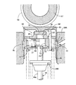
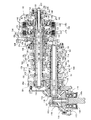
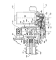
図1〜図15は本発明の一実施例を示すものであり、図1は自動二輪車の左側面図、図2は図1の2−2線矢視方向から見た車体フレームおよびエンジン本体の平面図、図3はパワーユニットの左側面図、図4はパワーユニットの右側面図、図5は図3の5−5線断面図、図6は図5の6−6線断面図、図7は図3の7−7線断面図、図8は図7の8−8線断面図、図9は図8の要部拡大断面図、図10は歯車変速機構およびクラッチ装置の縦断面図、図11は図10の要部拡大図、図12は図3の12−12線拡大断面図、図13は図12の13−13線拡大断面図、図14は図3の要部拡大図、図15は油圧系の構成を示す系統図である。   1 to 15 show an embodiment of the present invention. FIG. 1 is a left side view of a motorcycle. FIG. 2 is a view of a vehicle body frame and an engine body viewed from the direction of arrows 2-2 in FIG. 3 is a left side view of the power unit, FIG. 4 is a right side view of the power unit, FIG. 5 is a sectional view taken along line 5-5 in FIG. 3, FIG. 6 is a sectional view taken along line 6-6 in FIG. 3 is a sectional view taken along line 7-7 in FIG. 3, FIG. 8 is a sectional view taken along line 8-8 in FIG. 7, FIG. 9 is an enlarged sectional view of the main part in FIG. 11 is an enlarged view of essential parts of FIG. 10, FIG. 12 is an enlarged sectional view taken along line 12-12 of FIG. 3, FIG. 13 is an enlarged sectional view taken along line 13-13 of FIG. 15 is a system diagram showing the configuration of the hydraulic system.

先ず図1において、自動二輪車の車体フレームFは、前輪WFを軸支するフロントフォーク25を操向可能に使用するヘッドパイプ26と、該ヘッドパイプ26から後下がりに延びる左右一対のメインフレーム27…と、両メインフレーム27…の後部に連設されて下方に延びる左右一対のピボットプレート28…とを有しており、ピボットプレート28…に前端が揺動可能に支承されるスイングアーム29の後部に後輪WRが軸支される。しかも前記ピボットプレート28の下部および前記スイングアーム29の前部間にはリンク30が設けられ、前記ピボットプレート28の上部および前記リンク30間にはクッションユニット31が設けられる。   Referring to FIG. 1, a motorcycle body frame F includes a head pipe 26 that can be used to steer a front fork 25 that pivotally supports a front wheel WF, and a pair of left and right main frames 27 that extend rearwardly downward from the head pipe 26. And a pair of left and right pivot plates 28 connected to the rear portions of the main frames 27 and extending downward, and the rear portion of the swing arm 29 that is pivotally supported by the pivot plates 28. The rear wheel WR is pivotally supported. In addition, a link 30 is provided between the lower part of the pivot plate 28 and the front part of the swing arm 29, and a cushion unit 31 is provided between the upper part of the pivot plate 28 and the link 30.

前記メインフレーム27…およびピボットプレート28…には、パワーユニットPが懸架、搭載されており、該パワーユニットPから出力される回転動力は前後に延びるドライブシャフト32を介して前記後輪WRに伝達される。   A power unit P is suspended and mounted on the main frames 27 and the pivot plates 28, and the rotational power output from the power unit P is transmitted to the rear wheel WR via a drive shaft 32 extending in the front-rear direction. .

図2を併せて参照して、前記パワーユニットPは、たとえば4気筒のV型であるエンジンEを有しており、このエンジンEのエンジン本体33が、平面視で前記両メインフレーム27,27内に配置される。また前記エンジン本体33もしくは車体フレームFには、サイドスタンド34が取付けられており、この実施例では、図1で示すように、前記車体フレームFにおける左側のピボットプレート28の下部にサイドスタンド34が取付けられる。したがってサイドスタンド34を立てて駐車したときに自動二輪車は左側に傾斜した状態となる。   Referring also to FIG. 2, the power unit P includes, for example, a 4-cylinder V-type engine E, and an engine body 33 of the engine E is disposed in the main frames 27 and 27 in a plan view. Placed in. Further, a side stand 34 is attached to the engine body 33 or the vehicle body frame F. In this embodiment, as shown in FIG. 1, the side stand 34 is attached to the lower portion of the left pivot plate 28 in the vehicle body frame F. . Accordingly, when the side stand 34 is parked, the motorcycle is inclined to the left.

図3および図4において、前記エンジンEのエンジン本体33は、自動二輪車への搭載状態で前方に位置する前部バンクBFと、該前部バンクBFよりも後方に位置する後部バンクBRとを有してV型の水冷式に構成されるものであり、両バンクBF,BRに共通なクランクケース35に、自動二輪車の車幅方向すなわち左右方向に沿うクランクシャフト36が回転自在に支承される。   3 and 4, the engine body 33 of the engine E has a front bank BF located in front of the motorcycle E and a rear bank BR located rearward of the front bank BF. Thus, a V-shaped water-cooled type is constructed, and a crankshaft 36 along the vehicle width direction, that is, the left-right direction of the motorcycle is rotatably supported by a crankcase 35 common to both banks BF and BR.

クランクケース35は、上部ケース半体35aおよび下部ケース半体35bが結合されて成るものであり、V字形をなすようにして前部および後部バンクBF,BRが上部ケース半体35aに一体に形成され、前記クランクシャフト36の軸線は前記上部ケース半体35aおよび前記下部ケース半体35bの結合面37上に配置される。   The crankcase 35 is formed by combining an upper case half 35a and a lower case half 35b, and the front and rear banks BF and BR are formed integrally with the upper case half 35a so as to form a V shape. The axis of the crankshaft 36 is disposed on the coupling surface 37 of the upper case half 35a and the lower case half 35b.

前部バンクBFは、クランクケース35の上部ケース半体35aに一体に連なる前部シリンダブロック38Fと、前部シリンダブロック38Fに結合される前部シリンダヘッド39Fと、前部シリンダヘッド39Fに結合される前部ヘッドカバー40Fとで構成され、後部バンクBRは、クランクケース35の上部ケース半体35aに一体に連なる後部シリンダブロック38Rと、後部シリンダブロック38Rに結合される後部シリンダヘッド39Rと、後部シリンダヘッド39Rに結合される後部ヘッドカバー40Rとで構成され、前記クランクケース35の下部にはオイルパン41が結合される。   The front bank BF is coupled to the front cylinder block 38F integrally connected to the upper case half 35a of the crankcase 35, the front cylinder head 39F coupled to the front cylinder block 38F, and the front cylinder head 39F. The rear bank BR includes a rear cylinder block 38R integrally connected to the upper case half 35a of the crankcase 35, a rear cylinder head 39R coupled to the rear cylinder block 38R, and a rear cylinder. The rear head cover 40R is coupled to the head 39R, and an oil pan 41 is coupled to the lower portion of the crankcase 35.

前部シリンダブロック38Fには、前記クランクシャフト36の軸線方向に並ぶ2つのシリンダボア42…が形成されており、前部シリンダブロック38Fは、エンジン本体33の車体フレームFへの懸架状態で前記シリンダボア42…の軸線を前上がりに傾斜させるようにしてクランクケース35に結合される。また後部シリンダブロック38Rには、前記クランクシャフト36の軸線方向に並ぶ2つのシリンダボア42…が形成されており、後部シリンダブロック38Rは、エンジン本体33の車体フレームFへの懸架状態で、各シリンダボア42…の軸線を後上がりに傾斜させるようにしてクランクケース35に結合される。而して前部バンクBFの両シリンダボア42…にそれぞれ摺動可能に嵌合されるピストン43…と、後部バンクBRの両シリンダボア42…にそれぞれ摺動可能に嵌合されるピストン43…とが、前記クランクシャフト36に共通に連接される。   Two cylinder bores 42 aligned in the axial direction of the crankshaft 36 are formed in the front cylinder block 38F, and the front cylinder block 38F is suspended from the body frame F of the engine body 33 in the cylinder bore 42. The axis of... Is coupled to the crankcase 35 so as to incline forward. The rear cylinder block 38R is formed with two cylinder bores 42 aligned in the axial direction of the crankshaft 36. The rear cylinder block 38R is in a state of being suspended from the body frame F of the engine main body 33, and each cylinder bore 42 is formed. The axis of... Is coupled to the crankcase 35 so as to incline backward. Thus, pistons 43 are slidably fitted to both cylinder bores 42 of the front bank BF, and pistons 43 are slidably fitted to both cylinder bores 42 of the rear bank BR. The crankshaft 36 is connected in common.

而して図2で示すように、前部バンクBFにおける両シリンダボア42…間の間隔LFは、後部バンクBRにおける両シリンダボア42…間の間隔LRよりも大きく設定されており、クランクシャフト36の軸線方向での後部バンクBRの幅は、正面視では前部バンクBFで隠されるようにして該前部バンクBFの前記幅よりも小さく設定されている。   Thus, as shown in FIG. 2, the distance LF between the cylinder bores 42 in the front bank BF is set larger than the distance LR between the cylinder bores 42 in the rear bank BR. The width of the rear bank BR in the direction is set smaller than the width of the front bank BF so as to be hidden by the front bank BF in a front view.

図5および図6において、前部シリンダヘッド39Fには、各シリンダボア42…毎に一対ずつの吸気弁44…が弁ばね46…で閉弁方向に付勢されて開閉作動可能に配設されるとともに、一対ずつの排気弁45…が弁ばね47…で閉弁方向に付勢されて開閉作動可能に配設されており、これらの吸気弁44…および排気弁45…は、前部バンク側動弁装置48Fによって開閉駆動される。   5 and 6, the front cylinder head 39F is provided with a pair of intake valves 44 for each cylinder bore 42, which are urged in a valve closing direction by valve springs 46 so as to be opened and closed. In addition, a pair of exhaust valves 45 are urged in a valve closing direction by valve springs 47 so as to be opened and closed, and these intake valves 44 and exhaust valves 45 are arranged on the front bank side. The valve is driven to open and close by a valve operating device 48F.

前部バンク側動弁装置48Fは、前記クランクシャフト36と平行な軸線を有して前部シリンダヘッド39Fに回転自在に支承されるとともに吸気弁44…の上方に配置されるカムシャフト49と、該カムシャフト49に設けられた複数(この実施例では4つ)の吸気側カム50…および吸気弁44…間に介装されて前部シリンダヘッド39Fに摺動可能に嵌合される吸気側バルブリフタ51…と、前記カムシャフト49に設けられた複数(この実施例では4つ)の排気側カム52…に転がり接触するローラ53…を一端に有するとともに他端には各排気弁45…のステム45a…の上端に当接するタペットねじ54…が進退位置を調節可能として螺合されるロッカアーム55…とを備え、ロッカアーム55…は、前記カムシャフト49と平行な軸線を有して前部シリンダヘッド39Fに固定配置されるロッカシャフト56で揺動可能に支承される。   The front bank side valve operating device 48F has a shaft parallel to the crankshaft 36 and is rotatably supported by the front cylinder head 39F, and is disposed above the intake valves 44. An intake side that is interposed between a plurality (four in this embodiment) of intake side cams 50 and intake valves 44 provided on the camshaft 49 and is slidably fitted to the front cylinder head 39F. A valve lifter 51... And a plurality of (four in this embodiment) exhaust side cams 52 provided on the camshaft 49 are in rolling contact with one end 53, and the other end of each exhaust valve 45. A tappet screw 54 that abuts on the upper end of the stem 45a is provided with a rocker arm 55 that is screwed so that the advance / retreat position can be adjusted, and the rocker arm 55 is flat with the camshaft 49. Is swingably supported by the rocker shaft 56 fixedly disposed on the front cylinder head 39F have such axis.

図7および図8において、後部シリンダヘッド39Rには、各シリンダボア42…毎に一対ずつの吸気弁44…および一対ずつの排気弁45…が弁ばね280…,281…で閉弁方向に付勢されて開閉作動可能に配設されており、これらの吸気弁44…および排気弁45…は、後部バンク側動弁装置48Rによって開閉駆動される。   7 and 8, in the rear cylinder head 39R, a pair of intake valves 44 and a pair of exhaust valves 45 are urged in the valve closing direction by valve springs 280 and 281 for each cylinder bore 42, respectively. The intake valves 44... And the exhaust valves 45 are driven to open and close by the rear bank side valve operating device 48R.

後部バンク側動弁装置48Rは、前記クランクシャフト36と平行な軸線を有して後部シリンダヘッド39Rに回転自在に支承されるとともに吸気弁44…の上方に配置される吸気側カムシャフト57と、前記クランクシャフト36と平行な軸線を有して後部シリンダヘッド39Rに回転自在に支承されるとともに排気弁45…の上方に配置される排気側カムシャフト58と、吸気側カムシャフト57に設けられる複数(この実施例では4つ)の吸気側カム59…および吸気弁44…間に介装されて後部シリンダヘッド39Rに摺動可能に嵌合される吸気側バルブリフタ60…と、排気側カムシャフト58に設けられる複数(この実施例では4つ)の排気側カム61…および排気弁45…間に介設されて後部シリンダヘッド39Rに摺動可能に嵌合される排気側バルブリフタ62…とを備える。   The rear bank side valve operating device 48R has an axis parallel to the crankshaft 36 and is rotatably supported by the rear cylinder head 39R and is disposed above the intake valves 44, A plurality of exhaust side camshafts 58 that are rotatably supported by the rear cylinder head 39R and have an axis parallel to the crankshaft 36 and disposed above the exhaust valves 45, and a plurality of intake side camshafts 57 are provided. (In this embodiment, four) intake side cams 59 and intake valves 44 are interposed between intake side valve lifters 60 slidably fitted to the rear cylinder head 39R, and exhaust side camshaft 58. Are provided between a plurality of (four in this embodiment) exhaust-side cams 61 and exhaust valves 45 and are slidable on the rear cylinder head 39R. An exhaust-side valve lifters 62 ... and to be fitted.

しかも後部バンク側動弁装置48Rには、後部バンクBRの吸気弁44…の作動態様を開閉作動状態および閉弁休止状態に切換可能とした吸気側弁作動態様変更機構63と、排気弁45…の作動態様を開閉作動状態および閉弁休止状態に切換可能とした排気側弁作動態様変更機構64とが付設される。   In addition, the rear bank side valve operating device 48R includes an intake side valve operating mode changing mechanism 63 that allows the operating mode of the intake valves 44 of the rear bank BR to be switched between an open / closed operating state and a closed valve closed state, an exhaust valve 45. And an exhaust side valve operation mode change mechanism 64 that can switch the operation mode between the open / close operation state and the closed valve stop state.

図9において、吸気側弁作動態様変更機構63は、吸気側バルブリフタ60…に関連して設けられるものであり、吸気側バルブリフタ60に摺動可能に嵌合されるピンホルダ65と、吸気側バルブリフタ60の内面との間に油圧室66を形成してピンホルダ65に摺動可能に嵌合されるスライドピン67と、油圧室66の容積を縮少する方向にスライドピン67を付勢するばね力を発揮してスライドピン67およびピンホルダ65間に設けられる戻しばね68と、スライドピン67の軸線まわりの回転を阻止してピンホルダ65およびスライドピン67間に設けられるストッパピン69とを備える。   9, the intake side valve operation mode changing mechanism 63 is provided in relation to the intake side valve lifters 60..., A pin holder 65 slidably fitted to the intake side valve lifters 60, and the intake side valve lifters 60. A hydraulic pin 66 is formed between the inner surface of the hydraulic chamber 66 and is slidably fitted to the pin holder 65. A spring force is applied to bias the slide pin 67 in a direction to reduce the volume of the hydraulic chamber 66. A return spring 68 that is provided between the slide pin 67 and the pin holder 65 and a stopper pin 69 provided between the pin holder 65 and the slide pin 67 that prevents rotation of the slide pin 67 around the axis line is provided.

ピンホルダ65の外周には環状溝71が設けられており、吸気側バルブリフタ60の軸線と直交する軸線を有して一端を前記環状溝71に開口せしめるとともに他端を閉塞した有底の摺動孔72がピンホルダ65に設けられる。またピンホルダ65には、弁ばね280で閉弁方向に付勢された吸気弁44におけるステム44aの先端部を挿通せしめる挿通孔73と、該挿通孔73との間に摺動孔72を挟む延長孔74とが、吸気弁44におけるステム44aの先端部を収容可能として同軸に設けられる。吸気側バルブリフタ60の閉塞端側で延長孔74の端部を塞ぐ円盤状のシム75がピンホルダ65に嵌合され、このシム75に当接する突部76が吸気側バルブリフタ60の閉塞端内面中央部に一体に設けられる。   An annular groove 71 is provided on the outer periphery of the pin holder 65, and has a bottomed sliding hole having an axis perpendicular to the axis of the intake valve lifter 60 and having one end opened to the annular groove 71 and the other end closed. 72 is provided on the pin holder 65. The pin holder 65 has an insertion hole 73 through which the tip of the stem 44 a of the intake valve 44 urged by the valve spring 280 in the valve closing direction is inserted, and an extension that sandwiches the sliding hole 72 between the insertion hole 73. A hole 74 is provided coaxially so as to be able to accommodate the tip of the stem 44a of the intake valve 44. A disc-shaped shim 75 that closes the end of the extension hole 74 on the closed end side of the intake side valve lifter 60 is fitted into the pin holder 65, and the protrusion 76 that contacts the shim 75 is the central part of the closed end inner surface of the intake side valve lifter 60. Are integrally provided.

ピンホルダ65の摺動孔72にはスライドピン67が摺動自在に嵌合される。このスライドピン67の一端と吸気側バルブリフタ60の内面との間には、環状溝71に通じる油圧室66が形成され、スライドピン67の他端と摺動孔72の閉塞端との間に形成されるばね室77内には戻しばね68が収納される。   A slide pin 67 is slidably fitted in the slide hole 72 of the pin holder 65. A hydraulic chamber 66 communicating with the annular groove 71 is formed between one end of the slide pin 67 and the inner surface of the intake side valve lifter 60, and is formed between the other end of the slide pin 67 and the closed end of the slide hole 72. A return spring 68 is accommodated in the spring chamber 77.

スライドピン67の軸方向中間部には、前記挿通孔73および延長孔74に同軸に連なり得る収容孔78が前記ステム44aの先端部を収容可能として設けられ、該収容孔78の挿通孔73側の端部は、挿通孔73に対向してスライドピン67の下部外側面に形成される平坦な当接面79に開口される。而して当接面79はスライドピン67の軸線方向に沿って比較的長く形成されるものであり、収容孔78は、当接面79の油圧室66側の部分に開口される。   An accommodation hole 78 that can be coaxially connected to the insertion hole 73 and the extension hole 74 is provided in the intermediate portion in the axial direction of the slide pin 67 so as to accommodate the distal end portion of the stem 44a. This end is opened to a flat contact surface 79 formed on the lower outer surface of the slide pin 67 so as to face the insertion hole 73. Thus, the contact surface 79 is formed relatively long along the axial direction of the slide pin 67, and the accommodation hole 78 is opened at a portion of the contact surface 79 on the hydraulic chamber 66 side.

このようなスライドピン67は、油圧室66の油圧により該スライドピン67の一端側に作用する油圧力と、戻しばね68によりスライドピン67の他端側に作用するばね力とが均衡するようにして軸方向に摺動するものであり、油圧室66の油圧が低圧であるときの非作動時には、収容孔78を挿通孔73および延長孔74の軸線からずらせて前記ステム44aの先端を当接面79に当接させるように図9の右側に移動し、油圧室66の油圧が高圧になった作動状態では、挿通孔73に挿通されている前記ステム44aの先端部を収容孔78および延長孔74に収容せしめるように図9の左側に移動する。   Such a slide pin 67 balances the hydraulic pressure acting on one end side of the slide pin 67 by the hydraulic pressure of the hydraulic chamber 66 and the spring force acting on the other end side of the slide pin 67 by the return spring 68. When the hydraulic pressure in the hydraulic chamber 66 is low, the housing hole 78 is displaced from the axis of the insertion hole 73 and the extension hole 74 to contact the tip of the stem 44a. 9 is moved to the right side of FIG. 9 so as to be in contact with the surface 79, and when the hydraulic pressure in the hydraulic chamber 66 becomes high, the distal end portion of the stem 44a inserted through the insertion hole 73 is inserted into the accommodation hole 78 and the extension. It moves to the left side of FIG. 9 so as to be accommodated in the hole 74.

而してスライドピン67がその収容孔78を挿通孔73および延長孔74に同軸に連ならせる位置に移動したときには、吸気側カム59から作用する押圧力によって吸気側バルブリフタ60が摺動するのに応じてピンホルダ65およびスライドピン67も吸気側バルブリフタ60とともに吸気弁44側に移動するが、前記ステム44aの先端部が収容孔78および延長孔74に収容されるだけで吸気側バルブリフタ60およびピンホルダ65から吸気弁44に開弁方向の押圧力が作用することはなく、吸気弁44は休止したままとなる。またスライドピン67がその当接面79に前記ステム44aの先端部を当接させる位置に移動したときには、吸気側動弁カム59から作用する押圧力によって吸気側バルブリフタ60が摺動するのに応じたピンホルダ65およびスライドピン67の吸気弁44側への移動に伴い吸気弁44に開弁方向の押圧力が作用するので、吸気側カム59の回転に応じて吸気弁44が開閉作動する。   Thus, when the slide pin 67 moves to a position where the accommodation hole 78 is coaxially connected to the insertion hole 73 and the extension hole 74, the intake side valve lifter 60 slides due to the pressing force acting from the intake side cam 59. Accordingly, the pin holder 65 and the slide pin 67 move to the intake valve 44 side together with the intake side valve lifter 60. However, the intake side valve lifter 60 and the pin holder are merely accommodated in the accommodation hole 78 and the extension hole 74 at the tip end portion of the stem 44a. The pressure in the opening direction does not act on the intake valve 44 from 65, and the intake valve 44 remains at rest. Further, when the slide pin 67 moves to a position where the tip of the stem 44a comes into contact with the contact surface 79, the intake side valve lifter 60 slides due to the pressing force acting from the intake side valve cam 59. As the pin holder 65 and the slide pin 67 move to the intake valve 44 side, a pressing force in the valve opening direction acts on the intake valve 44, so that the intake valve 44 opens and closes according to the rotation of the intake side cam 59.

後部シリンダヘッド39Rには吸気側バルブリフタ60…を摺動自在に支承すべく該吸気側バルブリフタ60…を嵌合せしめる支持孔80…が設けられており、この支持孔80…の内面には、環状凹部81…が吸気側バルブリフタ60…を囲繞するようにして設けられ、吸気側バルブリフタ60…には、該吸気側バルブリフタ60…の支持孔80…内での摺動にかかわらず前記環状凹部81…を前記環状溝71…に連通させる連通孔70…が複数ずつ設けられる。また吸気側バルブリフタ60…および後部シリンダヘッド39R間には、吸気側バルブリフタ60…を吸気側カム59…に当接させる方向に付勢するばね82…が設けられる。   The rear cylinder head 39R is provided with a support hole 80 for fitting the intake side valve lifter 60 to slidably support the intake side valve lifter 60, and an inner surface of the support hole 80 is annular. Recesses 81 are provided so as to surround the intake-side valve lifters 60. The intake-side valve lifters 60 are provided with the annular recesses 81 regardless of sliding in the support holes 80 of the intake-side valve lifters 60. A plurality of communication holes 70 are provided to communicate with the annular grooves 71. Between the intake side valve lifters 60... And the rear cylinder head 39R, springs 82 are provided for urging the intake side valve lifters 60 in a direction to contact the intake side cams 59.

排気側弁作動態様変更機構64は、吸気側弁作動態様変更機構63と同様に構成されて排気側バルブリフタ62…に関連して設けられるものであり、高圧の油圧が作用したときに排気弁45を閉弁休止させる状態と、作用する油圧が低下したときに排気弁45を開閉作動せしめる状態とを切換可能である。   The exhaust side valve operation mode change mechanism 64 is configured in the same manner as the intake side valve operation mode change mechanism 63 and is provided in association with the exhaust side valve lifters 62... Can be switched between a state in which the exhaust valve 45 is closed and a state in which the exhaust valve 45 is opened and closed when the acting hydraulic pressure decreases.

すなわち後部バンク側動弁装置48Rは、吸気側弁作動態様変更機構63…および排気側弁作動態様変更機構64…の作動制御によって、後部バンクBRにおける2つの気筒の吸気弁44…および排気弁45…を開閉作動せしめる状態と、後部バンクBRにおける2つの気筒の吸気弁44…および排気弁45…を閉弁休止して気筒休止とする状態とを切換えることが可能である。   That is, the rear bank side valve operating device 48R is controlled by the intake side valve operation mode change mechanism 63 and the exhaust side valve operation mode change mechanism 64 to control the intake valves 44 and exhaust valves 45 of the two cylinders in the rear bank BR. It is possible to switch between a state in which the... Is opened and closed and a state in which the intake valves 44 and exhaust valves 45 of the two cylinders in the rear bank BR are closed and stopped.

再び図5において、エンジン本体33の車体フレームFへの搭載状態でのクランクシャフト36の左側端部には、発電機84が連結されるものであり、この発電機84は、クランクシャフト36に固定されるインナーロータ85と、該インナーロータ85を囲繞するアウターステータ86とで構成され、クランクケース35と、該クランクケース35の左側側面に結合される発電機カバー87とで構成される発電機収容室88に収容され、前記ステータ86は発電機カバー87に固定される。   In FIG. 5 again, a generator 84 is connected to the left end portion of the crankshaft 36 when the engine body 33 is mounted on the vehicle body frame F. The generator 84 is fixed to the crankshaft 36. Generator housing composed of an inner rotor 85 and an outer stator 86 surrounding the inner rotor 85, and a crankcase 35 and a generator cover 87 coupled to the left side surface of the crankcase 35. The stator 86 is housed in a chamber 88 and is fixed to a generator cover 87.

前記発電機カバー87の中央部内面には支持突部87aが突設されており、この支持突部87aにねじ部材285によってバスリング286が固着され、該バスリング285に前記アウターステータ86が連設される。而して前記バスリング285には、発電機84の発電電圧を制御する発電電圧制御ドライバ287が取付けられる。すなわち発電電圧制御用ドライバ287は前記バスリング285を介して発電機カバー87に取付けられることになる。   A support protrusion 87 a is provided on the inner surface of the central portion of the generator cover 87. A bus ring 286 is fixed to the support protrusion 87 a by a screw member 285, and the outer stator 86 is connected to the bus ring 285. Established. Thus, a power generation voltage control driver 287 for controlling the power generation voltage of the generator 84 is attached to the bus ring 285. That is, the generated voltage control driver 287 is attached to the generator cover 87 via the bus ring 285.

しかも前記ロータ86には、ロータ86側への動力伝達を可能とした一方向クラッチ89を介して歯車90が連結されており、この歯車90には、図示しない始動モータからの動力が伝達される。   In addition, a gear 90 is connected to the rotor 86 via a one-way clutch 89 that enables power transmission to the rotor 86 side, and power from a starter motor (not shown) is transmitted to the gear 90. .

一方、エンジン本体33の車体フレームFへの搭載状態でのクランクケース35の右側側面には、クランクケース35との間にクラッチ室91を形成するクラッチカバー92が結合されるものであり、前記クラッチ室91内で、前記クランクシャフト36には、駆動スプロケット93,94が固設される。一方の駆動スプロケット93は、前部バンク側動弁装置48Fにおけるカムシャフト49に、クランクシャフト36の回転動力を1/2の減速比で伝達する前部バンク側調時伝動機構95の一部を構成するものであり、前部バンク側調時伝動機構95は、前記駆動スプロケット93と、前記カムシャフト49の一端部(パワーユニットPの車体フレームFへの搭載状態では右端部)に設けられる被動スプロケット96とに無端状のカムチェーン97が巻き掛けられて成る。   On the other hand, a clutch cover 92 that forms a clutch chamber 91 with the crankcase 35 is coupled to the right side surface of the crankcase 35 when the engine main body 33 is mounted on the vehicle body frame F. Drive sprockets 93 and 94 are fixed to the crankshaft 36 in the chamber 91. One drive sprocket 93 is a part of the front bank side timing transmission mechanism 95 that transmits the rotational power of the crankshaft 36 at a reduction ratio of 1/2 to the camshaft 49 in the front bank side valve gear 48F. The front bank side timing transmission mechanism 95 includes a driven sprocket 93 and a driven sprocket provided at one end of the camshaft 49 (the right end when the power unit P is mounted on the vehicle body frame F). 96 and an endless cam chain 97 is wound around.

他方の前記駆動スプロケット94は、後部バンク側動弁装置48Rにおける吸気側および排気側カムシャフト57,58にクランクシャフト36の回転動力を1/2の減速比で伝達する後部バンク側調時伝動機構98の一部を構成するものであり、この後部バンク側調時伝動機構98は、前記駆動スプロケット94と、前記吸気側および排気側カムシャフト57,58の一端部(パワーユニットPの車体フレームFへの搭載状態では右端部)にそれぞれ設けられる被動スプロケット282…(図7参照)とに、無端状のカムチェーン99が巻き掛けられて成る。   The other drive sprocket 94 is a rear bank side timing transmission mechanism that transmits the rotational power of the crankshaft 36 to the intake side and exhaust side camshafts 57, 58 in the rear bank side valve operating device 48R at a reduction ratio of 1/2. 98, the rear bank side timing transmission mechanism 98 includes the drive sprocket 94 and one end of the intake and exhaust camshafts 57, 58 (to the vehicle body frame F of the power unit P). In the mounted state, an endless cam chain 99 is wound around driven sprockets 282 (see FIG. 7) provided respectively on the right end).

而して前部シリンダブロック38Fおよび前部シリンダヘッド39Fには、前記カムチェーン97を走行させるカムチェーン室100Fが形成され、後部シリンダブロック38Rおよび後部シリンダヘッド39Rには、前記カムチェーン99を走行させるカムチェーン室100Rが形成される。   Thus, the front cylinder block 38F and the front cylinder head 39F are formed with a cam chain chamber 100F for running the cam chain 97, and the rear cylinder block 38R and the rear cylinder head 39R run the cam chain 99. A cam chain chamber 100R is formed.

図10を併せて参照して、前記クランクシャフト36および後輪WR間の動力伝達経路は、クランクシャフト36側から順に一次減速装置101、クラッチ装置102、歯車変速機構103およびドライブシャフト32(図1参照)を備えており、一次減速装置101およびクラッチ装置102は前記クラッチ室91に収容され、歯車変速機構103はクランクケース35内に収容される。   Referring also to FIG. 10, the power transmission path between the crankshaft 36 and the rear wheel WR is the primary reduction gear 101, the clutch device 102, the gear transmission mechanism 103, and the drive shaft 32 (see FIG. 1) in order from the crankshaft 36 side. The primary speed reduction device 101 and the clutch device 102 are accommodated in the clutch chamber 91, and the gear transmission mechanism 103 is accommodated in the crankcase 35.

前記歯車変速機構103は、選択的に確立可能な複数変速段の歯車列たとえば第1〜第6速用歯車列G1,G2,G3,G4,G5,G6を備えてクランクケース35内に収納されており、第1メインシャフト105およびカウンタシャフト107間に第2、第4および第6速用歯車列G2,G4,G6が設けられるとともに、第1メインシャフト105を同軸にかつ相対回転自在に貫通する第2メインシャフト106および前記カウンタシャフト107間に第1、第3および第5速用歯車列G1,G3,G5が設けられて成る。   The gear transmission mechanism 103 includes gear trains of a plurality of shift stages that can be selectively established, for example, first to sixth gear trains G1, G2, G3, G4, G5, and G6, and is housed in the crankcase 35. The second, fourth and sixth speed gear trains G2, G4 and G6 are provided between the first main shaft 105 and the counter shaft 107, and pass through the first main shaft 105 coaxially and relatively rotatably. The first, third, and fifth speed gear trains G1, G3, and G5 are provided between the second main shaft 106 and the counter shaft 107.

前記クランクケース35は、クランクシャフト36の軸線方向に間隔をあけて相互に対向する一対の側壁35c,35dを含むものであり、クランクシャフト36と平行な軸線を有して円筒状に形成される第1メインシャフト105の中間部は、前記側壁35cを回転自在に貫通し、側壁35cおよび第1メインシャフト105間にはボールベアリング108が介装される。またクランクシャフト36と平行な軸線を有する第2メインシャフト106は、第1メインシャフト105との軸方向相対位置を一定としつつ第1メインシャフト105を相対回転可能に貫通するものであり、第1メインシャフト105および第2メインシャフト106間には複数のニードルベアリング109…が介装される。また第2メインシャフト106の他端部はクランクケース35の側壁35dにボールベアリング110を介して回転自在に支承される。   The crankcase 35 includes a pair of side walls 35c and 35d that are opposed to each other with an interval in the axial direction of the crankshaft 36, and is formed in a cylindrical shape having an axis parallel to the crankshaft 36. An intermediate portion of the first main shaft 105 passes through the side wall 35 c in a rotatable manner, and a ball bearing 108 is interposed between the side wall 35 c and the first main shaft 105. The second main shaft 106 having an axis parallel to the crankshaft 36 passes through the first main shaft 105 so as to be relatively rotatable while maintaining a constant axial relative position to the first main shaft 105. A plurality of needle bearings 109 are interposed between the main shaft 105 and the second main shaft 106. The other end of the second main shaft 106 is rotatably supported on the side wall 35d of the crankcase 35 via a ball bearing 110.

クランクシャフト36と平行な軸線を有するカウンタシャフト107の一端部はボールベアリング111を介して前記側壁35cに回転自在に支承され、カウンタシャフト107の他端部は、ボールベアリング112および環状のシール部材113を前記側壁35dとの間に介在させて該側壁35dを回転自在に貫通し、側壁35dからのカウンタシャフト107の突出端部には、駆動傘歯車114が固定される。この駆動傘歯車114には自動二輪車の前後方向に延びる回転軸線を有する被動傘歯車115が噛合される。   One end of the countershaft 107 having an axis parallel to the crankshaft 36 is rotatably supported on the side wall 35c via the ball bearing 111, and the other end of the countershaft 107 is connected to the ball bearing 112 and the annular seal member 113. Is interposed between the side wall 35d and the side wall 35d so as to rotate freely. A driving bevel gear 114 is fixed to the protruding end of the countershaft 107 from the side wall 35d. The driving bevel gear 114 is meshed with a driven bevel gear 115 having a rotation axis extending in the front-rear direction of the motorcycle.

ところで駆動傘歯車114および被動傘歯車115は、前記クランクケース35の前記側壁35dの一部を覆って前記側壁35dに着脱可能に結合される第1歯車カバー116と、第1歯車カバー116に着脱可能に結合される第2歯車カバー117と、前記側壁35dとで形成される歯車室118内で相互に噛合するものであり、被動傘歯車115が同軸に備える軸部115aは第2歯車カバー117を回転自在に貫通し、前記軸部115aおよび第2歯車カバー117間には、ボールベアリング119と、該ボールベアリング119の外方に位置する環状のシール部材120とが介装される。また被動傘歯車115には支持軸121の一端部が嵌合されており、該支持軸121の他端部は、ローラベアリング122を介して第1歯車カバー116に回転自在に支承される。而して前記軸部115aは、前記ドライブシャフト32に連結される。   By the way, the driving bevel gear 114 and the driven bevel gear 115 cover a part of the side wall 35d of the crankcase 35 and are detachably coupled to the side wall 35d, and are attached to and detached from the first gear cover 116. The second gear cover 117 that can be coupled and the side wall 35d are meshed with each other in a gear chamber 118, and the shaft portion 115a that the driven bevel gear 115 is coaxial with has a second gear cover 117. And a ball bearing 119 and an annular seal member 120 positioned outside the ball bearing 119 are interposed between the shaft 115a and the second gear cover 117. One end of a support shaft 121 is fitted to the driven bevel gear 115, and the other end of the support shaft 121 is rotatably supported on the first gear cover 116 via a roller bearing 122. Thus, the shaft portion 115a is connected to the drive shaft 32.

図11を併せて参照して、前記クラッチ装置102は、前記歯車変速機構103およびクランクシャフト36間に設けられる第1および第2クラッチ124,125を有してツイン式に構成されるものであり、前記クランクシャフト36の前記発電機84とは反対側の端部側でクランクケース35の側方、すなわちエンジン本体33の車体フレームFへの搭載状態でクランクケース35の右側側方に配設されて前記クラッチ室91に収容される。   Referring also to FIG. 11, the clutch device 102 has a first and second clutches 124 and 125 provided between the gear transmission mechanism 103 and the crankshaft 36, and is configured in a twin type. The crankshaft 36 is disposed on the side opposite to the generator 84 on the side of the crankcase 35, that is, on the right side of the crankcase 35 when the engine body 33 is mounted on the vehicle body frame F. In the clutch chamber 91.

第1クラッチ124は、前記クランクシャフト36および第1メインシャフト105の一端部間に設けられ、第2クラッチ125は、前記クランクシャフト36および第2メインシャフト106の一端部間に設けられる。而して前記クランクシャフト36からの動力は、第1および第2クラッチ124,125に共通であるクラッチアウタ126に、一次減速装置101およびダンパスプリング127を介して入力される。   The first clutch 124 is provided between one end portions of the crankshaft 36 and the first main shaft 105, and the second clutch 125 is provided between one end portions of the crankshaft 36 and the second main shaft 106. Thus, the power from the crankshaft 36 is input to the clutch outer 126 common to the first and second clutches 124 and 125 via the primary reduction gear 101 and the damper spring 127.

一次減速装置101は、前記駆動スプロケット94よりも外方で前記クランクシャフト36に設けられる駆動歯車128と、第1メインシャフト105に相対回転可能に支承されて駆動歯車128に噛合する被動歯車129とから成り、被動歯車129が、前記クラッチアウタ126にダンパスプリング127を介して連結される。   The primary reduction gear 101 includes a drive gear 128 provided on the crankshaft 36 outside the drive sprocket 94, and a driven gear 129 that is rotatably supported by the first main shaft 105 and meshes with the drive gear 128. The driven gear 129 is connected to the clutch outer 126 via a damper spring 127.

一次減速装置101よりも外方でクランクシャフト36の軸端には、図5で示すようにパルサ268が取付けられており、該パルサ268を検出することでクランクシャフト36の回転数を検出する回転数検出器269がクラッチカバー92の内面に取付けられる。またクラッチカバー92には、パルサ268を点検するための点検孔270が設けられるが、この点検孔270は、極力小径化するためにクランクシャフト36の軸線から偏心してクラッチカバー92に設けられ、該点検孔270は着脱可能な蓋部材271で閉じられる。   As shown in FIG. 5, a pulsar 268 is attached to the shaft end of the crankshaft 36 outside the primary reduction gear 101, and the rotation for detecting the rotational speed of the crankshaft 36 by detecting the pulsar 268 is provided. A number detector 269 is attached to the inner surface of the clutch cover 92. The clutch cover 92 is provided with an inspection hole 270 for inspecting the pulsar 268. The inspection hole 270 is provided in the clutch cover 92 eccentrically from the axis of the crankshaft 36 in order to reduce the diameter as much as possible. The inspection hole 270 is closed with a detachable lid member 271.

第1クラッチ124は、前記クラッチアウタ126と、該クラッチアウタ126で同軸に囲繞されるとともに第1メインシャフト105に相対回転不能に結合される第1クラッチインナ131と、前記クラッチアウタ126に相対回転不能に係合される複数枚の第1摩擦板132…と、第1クラッチインナ131に相対回転不能に係合されるとともに第1摩擦板132…と交互に配置される複数枚の第2摩擦板133…と、相互に重なって配置される第1および第2摩擦板132…,133…に対向して第1クラッチインナ131に設けられる第1受圧板134と、第1および第2摩擦板132…,133…を第1受圧板134との間に挟む第1ピストン135と、第1ピストン135を付勢する第1ばね136とを備える。   The first clutch 124 is relatively rotated with respect to the clutch outer 126, the first clutch inner 131 that is coaxially surrounded by the clutch outer 126 and is coupled to the first main shaft 105 so as not to rotate relative to the clutch outer 126, and the clutch outer 126. A plurality of first friction plates 132 that are impossiblely engaged and a plurality of second friction plates that are engaged with the first clutch inner 131 so as not to be relatively rotatable and are alternately arranged with the first friction plates 132. .., A first pressure receiving plate 134 provided on the first clutch inner 131 opposite to the first and second friction plates 132, 133, which are arranged to overlap each other, and the first and second friction plates , 133... Are sandwiched between the first pressure receiving plate 134 and a first spring 136 that biases the first piston 135.

第1ピストン135の背面を臨ませる第1油圧室137を第1ピストン135との間に形成する端壁部材138が第1クラッチインナ131に固定的に配設されており、第1油圧室137の油圧増大に応じて第1ピストン135は、第1および第2摩擦板132…,133…を第1受圧板134との間に挟圧するように作動し、それにより第1クラッチ124がクラッチアウタ126にクランクシャフト36から伝達される動力を第1メインシャフト105に伝達する接続状態となる。また第1クラッチインナ131および第1ピストン135間には第1ピストン135の前面を臨ませるキャンセラー室139が形成されており、前記第1ばね136は、第1油圧室137の容積を減少する側にばね力を発揮するようにしてキャンセラー室139に収容される。   An end wall member 138 that forms a first hydraulic chamber 137 that faces the back surface of the first piston 135 with the first piston 135 is fixedly disposed on the first clutch inner 131, and the first hydraulic chamber 137. The first piston 135 operates to clamp the first and second friction plates 132, 133,... Between the first pressure plate 134 and the first clutch 124 as a clutch outer. In this state, the power transmitted from the crankshaft 36 to 126 is transmitted to the first main shaft 105. In addition, a canceller chamber 139 is formed between the first clutch inner 131 and the first piston 135 so that the front surface of the first piston 135 faces, and the first spring 136 is on the side where the volume of the first hydraulic chamber 137 is reduced. It is accommodated in the canceller chamber 139 so as to exert a spring force.

しかもキャンセラー室139は、歯車変速機構103の各潤滑部ならびに第1および第2メインシャフト105,106間にオイルを供給するために第2メインシャフト106に同軸に設けられた第1オイル通路140に連通される。したがって減圧状態での第1油圧室137のオイルに回転に伴う遠心力が作用して第1ピストン135を押圧する力が生じても、キャンセラー室139のオイルにも同様に遠心力が作用するので、第1ピストン135が、第1および第2摩擦板132…,133…を第1受圧板134との間に挟む側に不所望に移動してしまう状態が生じることが回避される。   In addition, the canceller chamber 139 is provided in a first oil passage 140 provided coaxially with the second main shaft 106 in order to supply oil between the lubricating portions of the gear transmission mechanism 103 and the first and second main shafts 105 and 106. Communicated. Therefore, even if centrifugal force accompanying rotation acts on the oil in the first hydraulic chamber 137 in the reduced pressure state and a force that presses the first piston 135 is generated, the centrifugal force acts on the oil in the canceller chamber 139 as well. It is avoided that the first piston 135 undesirably moves to the side sandwiching the first and second friction plates 132... 133 between the first pressure receiving plate 134.

第2クラッチ125は、前記第1クラッチ124を前記一次減速装置101との間に挟むようにして、第2メインシャフト106の軸線方向で第1クラッチ124と並ぶように配置されるものであり、前記クラッチアウタ126と、該クラッチアウタ126で同軸に囲繞されるとともに第2メインシャフト106に相対回転不能に結合される第2クラッチインナ141と、前記クラッチアウタ126に相対回転不能に係合される複数枚の第3摩擦板142…と、第2クラッチインナ141に相対回転不能に係合されるとともに第3摩擦板142…と交互に配置される複数枚の第4摩擦板143…と、相互に重なって配置される第3および第4摩擦板142…,143…対向して第2クラッチインナ141に設けられる第2受圧板144と、第3および第4摩擦板142…,143…を第2受圧板144との間に挟む第2ピストン145と、第2ピストン145を付勢する第2ばね146とを備える。   The second clutch 125 is arranged so as to be aligned with the first clutch 124 in the axial direction of the second main shaft 106 so as to sandwich the first clutch 124 with the primary reduction gear 101. An outer 126; a second clutch inner 141 that is coaxially surrounded by the clutch outer 126 and is relatively non-rotatably coupled to the second main shaft 106; and a plurality of sheets that are engaged with the clutch outer 126 so as not to be relatively rotatable. And a plurality of fourth friction plates 143 that are engaged with the second clutch inner 141 so as not to rotate relative to each other and are alternately arranged with the third friction plates 142. The third and fourth friction plates 142, 143,... Arranged opposite to each other, the second pressure receiving plate 144 provided on the second clutch inner 141 facing each other, And fourth friction plates 142 ..., provided with a second piston 145 which sandwich 143 ... to between the second pressure receiving plate 144, a second spring 146 which urges the second piston 145.

第2ピストン145の背面を臨ませる第2油圧室147を第2ピストン145との間に形成する端壁部材148が第2クラッチインナ141に固定的に配設されており、第2油圧室147の油圧増大に応じて第2ピストン145は、第3および第4摩擦板142…,143…を第2受圧板144との間に挟圧するように作動し、それにより第2クラッチ125がクラッチアウタ126にクランクシャフト36から伝達される動力を第2メインシャフト106に伝達する接続状態となる。また第2クラッチインナ141および第2ピストン145間には第2ピストン145の前面を臨ませるキャンセラー室149が形成されており、前記第2ばね146は、第2油圧室147の容積を減少する側にばね力を発揮するようにしてキャンセラー室149に収容される。   An end wall member 148 that forms a second hydraulic chamber 147 facing the back surface of the second piston 145 with the second piston 145 is fixedly disposed on the second clutch inner 141, and the second hydraulic chamber 147. The second piston 145 operates to clamp the third and fourth friction plates 142, 143,... With the second pressure receiving plate 144 in response to the increase in hydraulic pressure. In this state, the power transmitted from the crankshaft 36 to 126 is transmitted to the second main shaft 106. A canceller chamber 149 is formed between the second clutch inner 141 and the second piston 145 so that the front surface of the second piston 145 faces. The second spring 146 reduces the volume of the second hydraulic chamber 147. It is accommodated in the canceller chamber 149 so as to exert a spring force.

しかもキャンセラー室149は後述の第2オイル通路150に連通される。したがって減圧状態での第2油圧室147のオイルに回転に伴う遠心力が作用して第2ピストン145を押圧する力が生じても、キャンセラー室149のオイルにも同様に遠心力が作用するので、第2ピストン145が、第3および第4摩擦板142…,143…を第2受圧板144との間に挟む側に不所望に移動してしまう状態が生じることが回避される。   Moreover, the canceller chamber 149 communicates with a second oil passage 150 described later. Therefore, even if a centrifugal force due to rotation acts on the oil in the second hydraulic chamber 147 in the decompressed state and a force pressing the second piston 145 occurs, the centrifugal force acts on the oil in the canceller chamber 149 as well. It is avoided that the second piston 145 undesirably moves to the side sandwiching the third and fourth friction plates 142, 143,... With the second pressure receiving plate 144.

自動二輪車の進行方向前方に向かって右側から第1および第2クラッチ124,125を覆うクラッチカバー92の内面側には、第1、第2および第3隔壁部材151,152,153が取付けられる。而して第2メインシャフト106および第1隔壁部材151間には、第1クラッチ124の第1油圧室137に通じる第1油路154を形成する第1筒部材155が設けられ、第2メインシャフト106および第2隔壁部材152間には、第2クラッチ125のキャンセラー室149に通じる環状の第2オイル通路150を第1筒部材155との間に形成して第1筒部材155を同軸に囲繞する第2筒部材156が設けられ、第2メインシャフト106および第3隔壁部材153間には、第2油圧室147に通じる環状の第2油路157を第2筒部材156との間に形成して第2筒部材156を同軸に囲繞する第3筒部材158が設けられる。   First, second, and third partition members 151, 152, and 153 are attached to the inner surface side of the clutch cover 92 that covers the first and second clutches 124 and 125 from the right side toward the front in the traveling direction of the motorcycle. Thus, a first cylinder member 155 is provided between the second main shaft 106 and the first partition member 151 so as to form a first oil passage 154 that communicates with the first hydraulic chamber 137 of the first clutch 124. An annular second oil passage 150 communicating with the canceller chamber 149 of the second clutch 125 is formed between the shaft 106 and the second partition member 152 between the first cylinder member 155 and the first cylinder member 155 coaxially. A surrounding second cylinder member 156 is provided, and an annular second oil passage 157 leading to the second hydraulic chamber 147 is provided between the second main shaft 106 and the third partition wall member 153 between the second cylinder member 156 and the second cylinder member 156. A third cylinder member 158 that is formed and coaxially surrounds the second cylinder member 156 is provided.

再び図10において、歯車変速機構103の第1メインシャフト105およびカウンタシャフト107間には、クラッチ装置102とは反対側から順に第4速用歯車列G4、第6速用歯車列G6および第2速用歯車列G2が並ぶようにして設けられる。第2速用歯車列G2は、第1メインシャフト105に一体に設けられる第2速用駆動歯車160と、カウンタシャフト107に相対回転自在に支承されて第2速用駆動歯車160に噛合する第2速用被動歯車161とから成り、第6速用歯車列G6は、第1メインシャフト105に相対回転自在に支承される第6速用駆動歯車162と、カウンタシャフト107に軸方向の移動を可能としつつ相対回転不能に支承されて第6速用駆動歯車162に噛合する第6速用被動歯車163とから成り、第4速用歯車列G4は、第1メインシャフト105に軸方向の移動を可能としつつ相対回転不能に支承される第4速用駆動歯車164と、カウンタシャフト107に相対回転自在に支承されて第4速用駆動歯車164に噛合する第4速用被動歯車165とから成る。   In FIG. 10 again, the fourth gear train G4, the sixth gear train G6, and the second gear train are sequentially arranged between the first main shaft 105 and the counter shaft 107 of the gear transmission mechanism 103 from the side opposite to the clutch device 102. The speed gear train G2 is provided in a line. The second speed gear train G2 is a second speed drive gear 160 provided integrally with the first main shaft 105 and a second speed drive gear 160 that is rotatably supported by the counter shaft 107 and meshes with the second speed drive gear 160. The sixth-speed gear train G6 includes a second-speed driven gear 161, and a sixth-speed drive gear 162 that is rotatably supported on the first main shaft 105 and an axial movement of the countershaft 107. The fourth-speed gear train G4 is moved to the first main shaft 105 in the axial direction. The sixth-speed driven gear 163 is engaged with the sixth-speed drive gear 162 and is supported in a relatively non-rotatable manner. 4th-speed drive gear 164 supported so as not to rotate relative to the 4th-speed drive gear 164, which is supported relative to the countershaft 107 so as to be relatively rotatable and meshed with the 4th-speed drive gear 164. Consisting of.

第2速用被動歯車161および第4速用被動歯車165間でカウンタシャフト107には、第2速用被動歯車161に係合する状態、第4速用被動歯車165に係合する状態、ならびに第2速用被動歯車161および第4速用被動歯車165のいずれにも係合しない状態を切換え可能とした第1シフタ166が相対回転不能かつ軸方向移動可能に支承されており、この第1シフタ166に第6速用被動歯車163が一体に設けられる。また第4速用駆動歯車164は、第1メインシャフト105に相対回転不能にかつ軸方向移動可能に支承される第2シフタ167に一体に設けられており、第2シフタ167は、第6速用駆動歯車162への係合および係合解除を切換え可能である。   Between the second speed driven gear 161 and the fourth speed driven gear 165, the counter shaft 107 is engaged with the second speed driven gear 161, the fourth speed driven gear 165 is engaged, and A first shifter 166 that can be switched between a state in which it is not engaged with either the second speed driven gear 161 or the fourth speed driven gear 165 is supported so as not to be relatively rotatable and axially movable. The shifter 166 is integrally provided with a sixth speed driven gear 163. The fourth speed drive gear 164 is integrally provided with a second shifter 167 that is supported by the first main shaft 105 so as not to rotate relative to the first main shaft 105 and to be movable in the axial direction. The engagement and disengagement with the drive gear 162 can be switched.

而して第2シフタ167を第6速用駆動歯車162に係合しない状態で第1シフタ166を第2速用被動歯車161に係合することで第2速用歯車列G2が確立し、第2シフタ167を第6速用駆動歯車162に係合しない状態で第1シフタ166を第4速用被動歯車165に係合することで第4速用歯車列G4が確立し、第1シフタ166を中立状態として第2シフタ167を第6速用駆動歯車162に係合することにより第6速用歯車列G6が確立する。   Thus, the second speed gear train G2 is established by engaging the first shifter 166 with the second speed driven gear 161 without engaging the second shifter 167 with the sixth speed driving gear 162, By engaging the first shifter 166 with the fourth-speed driven gear 165 without engaging the second shifter 167 with the sixth-speed drive gear 162, the fourth-speed gear train G4 is established, and the first shifter is established. The sixth gear train G6 is established by engaging the second shifter 167 with the sixth-speed drive gear 162 with the 166 in the neutral state.

第1メインシャフト105の他端部からの第2メインシャフト106の突出部およびカウンタシャフト107間には、クラッチ装置102とは反対側から順に第1速用歯車列G1、第5速用歯車列G5および第3速用歯車列G3が並ぶようにして設けられる。第3速用歯車列G3は、第2メインシャフト106に軸方向の移動を可能としつつ相対回転不能に支承される第3速用駆動歯車168と、カウンタシャフト107に相対回転自在に支承されて第3速用駆動歯車168に噛合する第3速用被動歯車169とから成り、第5速用歯車列G5は、第2メインシャフト106に相対回転自在に支承される第5速用駆動歯車170と、カウンタシャフト107に軸方向の移動を可能としつつ相対回転不能に支承されて第5速用駆動歯車170に噛合する第5速用被動歯車171とから成り、第1速用歯車列G1は、第2メインシャフト106に一体に設けられる第1速用駆動歯車172と、カウンタシャフト107に相対回転自在に支承されて第1速用駆動歯車172に噛合する第1速用被動歯車173とから成る。   Between the protrusion of the second main shaft 106 from the other end of the first main shaft 105 and the counter shaft 107, the first gear train G1 and the fifth gear train are arranged in order from the side opposite to the clutch device 102. G5 and the third speed gear train G3 are provided so as to be aligned. The third-speed gear train G3 is supported by the second main shaft 106 so as to be axially movable and supported by the third-speed drive gear 168, which is supported so as not to rotate relative to the second main shaft 106, and the countershaft 107, so as to be relatively rotatable. The fifth-speed gear train G5 includes a third-speed driven gear 169 that meshes with the third-speed drive gear 168, and the fifth-speed gear train G5 is supported on the second main shaft 106 so as to be relatively rotatable. And a fifth-speed driven gear 171 that is supported by the countershaft 107 in the axial direction while being relatively non-rotatable and meshes with the fifth-speed drive gear 170. The first-speed gear train G1 includes: The first-speed drive gear 172 provided integrally with the second main shaft 106 and the first-speed driven gear 17 that is rotatably supported by the counter shaft 107 and meshes with the first-speed drive gear 172. Consisting of.

第3速用駆動歯車168は、第2メインシャフト106に相対回転不能かつ軸方向移動可能に支承される第3シフタ174に一体に設けられており、第3シフタ174は、第5速用駆動歯車への係合および係合解除を切換え可能である。第3速用被動歯車169および第1速用被動歯車173間でカウンタシャフト107には、第3速用被動歯車169に係合する状態、第1速用被動歯車173に係合する状態、ならびに第3速用被動歯車169および第1速用被動歯車173のいずれにも係合しない中立状態を切換え可能とした第4シフタ175が相対回転不能かつ軸方向移動可能に支承されており、この第4シフタ175に第5速用被動歯車171が一体に設けられる。   The third-speed drive gear 168 is integrally provided with a third shifter 174 that is supported by the second main shaft 106 so as not to rotate relative to the second main shaft 106 and to be axially movable. The third shifter 174 is a fifth-speed drive gear. The engagement and disengagement of the gear can be switched. Between the third-speed driven gear 169 and the first-speed driven gear 173, the countershaft 107 is engaged with the third-speed driven gear 169, is engaged with the first-speed driven gear 173, and A fourth shifter 175 that can switch a neutral state that is not engaged with any of the third-speed driven gear 169 and the first-speed driven gear 173 is supported so as to be non-rotatable and axially movable. The fourth shifter 175 is integrally provided with a fifth speed driven gear 171.

而して第3シフタ174を第5速用駆動歯車170に係合しない状態で第4シフタ175を第1速用被動歯車173に係合することで第1速用歯車列G1が確立し、第3シフタ174を第5速用駆動歯車170に係合しない状態で第4シフタ175を第3速用被動歯車169に係合することで第3速用歯車列G3が確立し、第4シフタ175を中立状態として第3シフタ174を第5速用駆動歯車170に係合することにより第5速用歯車列G5が確立する。   Thus, the first speed gear train G1 is established by engaging the fourth shifter 175 with the first speed driven gear 173 without engaging the third shifter 174 with the fifth speed drive gear 170, By engaging the fourth shifter 175 with the third-speed driven gear 169 without engaging the third shifter 174 with the fifth-speed drive gear 170, the third-speed gear train G3 is established, and the fourth shifter is established. The fifth gear train G5 is established by engaging the third shifter 174 with the fifth-speed drive gear 170 with 175 in the neutral state.

第1〜第4シフタ166,167,174,175は、第1〜第4シフトフォーク176,177,178,179で回転自在に保持されており、それらのシフトフォーク176〜179が、両メインシャフト105,106およびカウンタシャフト107の軸線方向に駆動されることにより、第1〜第4シフタ166,167,174,175が軸方向に作動することになる。   The first to fourth shifters 166, 167, 174, and 175 are rotatably held by the first to fourth shift forks 176, 177, 178, and 179, and these shift forks 176 to 179 are both main shafts. The first to fourth shifters 166, 167, 174, and 175 operate in the axial direction by being driven in the axial direction of the 105 and 106 and the counter shaft 107.

図12において、クランクケース35には、歯車変速機構103の一部を構成するシフトドラム180がクランクシャフト36の軸線と平行な軸線を有して回転自在に支承されており、第1〜第4シフトフォーク176〜179はシフトドラム180の外周に係合される。また前記各シフトフォーク176〜179は、シフトドラム180と平行な軸線を有してクランクケース35に支持されるシフトフォーク軸205,206にスライド可能に支承されており、シフトドラム180の回動に応じて前記各シフトフォーク176〜179がシフトフォーク軸205,206上をスライド作動することになる。   In FIG. 12, a shift drum 180 constituting a part of the gear transmission mechanism 103 is rotatably supported on the crankcase 35 with an axis parallel to the axis of the crankshaft 36. Shift forks 176 to 179 are engaged with the outer periphery of shift drum 180. Each of the shift forks 176 to 179 has an axis parallel to the shift drum 180 and is slidably supported by shift fork shafts 205 and 206 supported by the crankcase 35. Accordingly, the shift forks 176 to 179 slide on the shift fork shafts 205 and 206.

而してシフトドラム180が回動することにより、歯車変速機構103が変速作動するものであり、シフトドラム180の回動位置を変化させて歯車変速機構103の変速作動を制御する変速制御装置191が、クランクシャフト36の軸線に沿う方向で、図2で示すように、車体中心線CBに対して前記クラッチ装置102とは反対側でエンジン本体33に取付けられるものであり、この実施例ではエンジン本体33の車体フレームFへの搭載状態でクランクケース35の左側側面に取付けられる。   Thus, when the shift drum 180 is rotated, the gear transmission mechanism 103 performs a shift operation, and the shift control device 191 that controls the shift operation of the gear transmission mechanism 103 by changing the rotation position of the shift drum 180. However, as shown in FIG. 2, in the direction along the axis of the crankshaft 36, it is attached to the engine body 33 on the side opposite to the clutch device 102 with respect to the vehicle body center line CB. In this embodiment, the engine The main body 33 is attached to the left side surface of the crankcase 35 in a mounted state on the vehicle body frame F.

図13および図14を併せて参照して、前記変速制御装置191は、回転動力を発揮する電動モータ181と、該電動モータ181の回転動力を前記シフトドラム180に伝達する動力伝達装置207とを備えるものであり、動力伝達装置207の少なくとも一部および前記電動モータ181が前記シフトドラム180の軸線方向一端側で前記クランクケース35の側方に配置される。   Referring to FIG. 13 and FIG. 14 together, the shift control device 191 includes an electric motor 181 that exhibits rotational power, and a power transmission device 207 that transmits the rotational power of the electric motor 181 to the shift drum 180. At least a part of the power transmission device 207 and the electric motor 181 are arranged on one side in the axial direction of the shift drum 180 and on the side of the crankcase 35.

前記動力伝達装置207は、前記電動モータ181の出力回転数を減速するようにして該電動モータ181の回転動力を伝達する歯車減速機構182と、該歯車減速機構182から伝達される動力で回転するとともにその回転運動を前記シフトドラム180の回動運動に変換するようにして歯車減速機構182に連動、連結されるバレルカム183と、バレルカム183の回転に応じて前記シフトドラム180の同一軸線まわりに回動する円板状の伝動回転部材184と、該伝動回転部材184に相対回転不能に連結されてシフトドラム180を相対回動を可能としつつシフトドラム180を同軸に貫通する伝動軸185と、該伝動軸185および前記シフトドラム180間に設けられるロストモーションばね186とを備え、動力伝達装置207のうち歯車減速機構182、バレルカム183および伝動回転部材184が、前記クランクケース35の左側方に配置される。   The power transmission device 207 transmits the rotational power of the electric motor 181 so as to reduce the output rotational speed of the electric motor 181, and rotates with the power transmitted from the gear reduction mechanism 182. At the same time, the rotational movement of the shift drum 180 is converted into the rotational movement of the shift drum 180, and the barrel cam 183 is linked to and connected to the gear reduction mechanism 182. A disc-shaped transmission rotation member 184 that moves, a transmission shaft 185 that is connected to the transmission rotation member 184 so as not to be relatively rotatable and allows the shift drum 180 to rotate relatively, and coaxially penetrates the shift drum 180; A power transmission device comprising a transmission shaft 185 and a lost motion spring 186 provided between the shift drum 180 and Gear reduction mechanism 182 of 07, the barrel cam 183 and transmission rotation member 184 is disposed on the left side of the crankcase 35.

クランクケース35の左側面には、前記歯車減速機構182、バレルカム183および伝動回転部材184を収容する作動室187をクランクケース35との間に形成するケース部材188が締結されており、そのケース部材188の開口端を塞ぐようにして該ケース部材188に蓋部材189が取付けられる。而して前記シフトドラム180の回動軸線C1と直交する平面内に回転軸線C2を配置した前記電動モータ181は、モータ軸190を作動室187内に突入するようにして前記ケース部材188に取付けられる。   A case member 188 is formed on the left side surface of the crankcase 35. The case member 188 is formed between the crankcase 35 and an operating chamber 187 that accommodates the gear reduction mechanism 182, the barrel cam 183, and the transmission rotation member 184. A lid member 189 is attached to the case member 188 so as to close the open end of the 188. Thus, the electric motor 181 having the rotation axis C2 disposed in a plane orthogonal to the rotation axis C1 of the shift drum 180 is attached to the case member 188 so that the motor shaft 190 enters the working chamber 187. It is done.

前記バレルカム183の外周には螺旋状のカム溝197が設けられており、このバレルカム183の回転軸線C3は、前記電動モータ181および前記歯車減速機構182と同様に、前記シフトドラム180の回動軸線C1と直交する平面内に配置されるとともに、前記電動モータ181の回転軸線C2と平行にして配置される。   A spiral cam groove 197 is provided on the outer periphery of the barrel cam 183, and the rotation axis C3 of the barrel cam 183 is the rotation axis of the shift drum 180, similar to the electric motor 181 and the gear reduction mechanism 182. It arrange | positions in the plane orthogonal to C1, and is arrange | positioned in parallel with the rotating shaft C2 of the said electric motor 181.

前記歯車減速機構182は、前記電動モータ181のモータ軸190に設けられる駆動歯車192と、該駆動歯車192に噛合する第1中間歯車193と、第1中間歯車193とともに回転する第2中間歯車194と、前記バレルカム183に設けられて第2中間歯車194に噛合する被動歯車195とから成るものであり、この歯車減速機構182の回転軸線すなわち前記駆動歯車192、第1中間歯車193、第2中間歯車194および被動歯車195の回転軸線は、前記電動モータ181と同様に、前記シフトドラム180の回動軸線C1と直交する平面内に配置される。すなわち駆動歯車192の回転軸線が電動モータ181と同軸であり、被動歯車195の回転軸線はバレルカム183と同軸であり、第1中間歯車193および第2中間歯車194の回転軸線C4が、前記電動モータ181および前記バレルカム183と同様に、前記シフトドラム180の回動軸線C1と直交する平面内に配置される。   The gear reduction mechanism 182 includes a drive gear 192 provided on the motor shaft 190 of the electric motor 181, a first intermediate gear 193 that meshes with the drive gear 192, and a second intermediate gear 194 that rotates together with the first intermediate gear 193. And a driven gear 195 that is provided on the barrel cam 183 and meshes with the second intermediate gear 194. The rotational axis of the gear reduction mechanism 182, that is, the drive gear 192, the first intermediate gear 193, and the second intermediate gear. The rotation axes of the gear 194 and the driven gear 195 are arranged in a plane orthogonal to the rotation axis C 1 of the shift drum 180, similarly to the electric motor 181. That is, the rotational axis of the drive gear 192 is coaxial with the electric motor 181, the rotational axis of the driven gear 195 is coaxial with the barrel cam 183, and the rotational axes C4 of the first intermediate gear 193 and the second intermediate gear 194 are connected to the electric motor. Similarly to the barrel cam 183 and the barrel cam 183, the shift drum 180 is disposed in a plane orthogonal to the rotation axis C1.

而して前記シフトドラム第1および第2中間歯車193,194は前記ケース部材188および蓋部材189で両端部が回転自在に支承された回転軸196に設けられており、前記バレルカム183の両端部は、ケース部材188および蓋部材189に回転自在に支承される。   Thus, the shift drum first and second intermediate gears 193 and 194 are provided on a rotating shaft 196 whose both ends are rotatably supported by the case member 188 and the lid member 189, and both end portions of the barrel cam 183. Is rotatably supported by the case member 188 and the lid member 189.

一方、伝動回転部材184は、シフトドラム180と同一軸線まわり回転することを可能としてバレルカム183の外周に対向配置されており、この伝動回転部材184に、前記カム溝197に選択的に係合することを可能とした複数の係合ピン198,198…が周方向に等間隔をあけて設けられる。而してバレルカム183の回転に応じて複数の前記係合ピン198,198…が順次カム溝197に係合して送られることにより、シフトドラム180と同一軸線まわりの回転動力が、伝動回転部材184に伝達されることになる。   On the other hand, the transmission rotation member 184 is disposed opposite to the outer periphery of the barrel cam 183 so as to be able to rotate about the same axis as the shift drum 180, and selectively engages with the cam groove 197 on the transmission rotation member 184. A plurality of engaging pins 198, 198... That can be provided are provided at equal intervals in the circumferential direction. Thus, the plurality of engaging pins 198, 198... Are sequentially engaged with the cam groove 197 in accordance with the rotation of the barrel cam 183, so that the rotational power around the same axis as the shift drum 180 is transmitted. 184 to be transmitted.

前記伝動回転部材184には、シフトドラム180を同軸かつ相対回転自在に貫通する伝動軸185の一端部が同軸にかつ相対回転不能に結合されており、この伝動軸185の他端部およびシフトドラム180の他端部間にロストモーションばね186が設けられ、伝動軸185の回動による回動力はロストモーションばね186を介してシフトドラム180に伝達されることになる。   One end of a transmission shaft 185 that passes through the shift drum 180 coaxially and relatively rotatably is coupled to the transmission rotation member 184 coaxially and in a relatively non-rotatable manner. The other end of the transmission shaft 185 and the shift drum A lost motion spring 186 is provided between the other end portions of 180, and the rotational force generated by the rotation of the transmission shaft 185 is transmitted to the shift drum 180 via the lost motion spring 186.

シフトドラム180の回動位置を検出するためにシフトセンサ199がケース部材188に取付けられ、このシフトセンサ199の検出軸200はケース部材188で回転自在に支承される。   A shift sensor 199 is attached to the case member 188 in order to detect the rotational position of the shift drum 180, and the detection shaft 200 of the shift sensor 199 is rotatably supported by the case member 188.

而して前記シフトドラム180とともに回転する駆動歯車201に第3中間歯車202が噛合され、第3中間歯車202とともに回転する第4中間歯車203に、前記検出軸200に設けられる被動歯車204が噛合される。   Thus, the third intermediate gear 202 is engaged with the drive gear 201 that rotates together with the shift drum 180, and the driven gear 204 provided on the detection shaft 200 is engaged with the fourth intermediate gear 203 that rotates together with the third intermediate gear 202. Is done.

しかも前記電動モータ181および前記シフトドラム180は、図14で明示するように、シフトドラム180の軸線方向から見て少なくとも一部を重ねるように配置されており、また前記電動モータ181および前記バレルカム183は少なくとも一部がシフトドラム180の軸線方向から見て重なるようにして配置されており、また電動モータ181、バレルカム183およびシフトドラム180が、該シフトドラム180の軸線方向から見て少なくとも一部を重ねるように配置される。   Moreover, as clearly shown in FIG. 14, the electric motor 181 and the shift drum 180 are arranged so as to overlap at least partially when viewed from the axial direction of the shift drum 180, and the electric motor 181 and the barrel cam 183 are arranged. Are arranged such that at least a portion thereof overlaps when viewed from the axial direction of the shift drum 180, and the electric motor 181, the barrel cam 183, and the shift drum 180 are at least partially viewed from the axial direction of the shift drum 180. Arranged to overlap.

また前記電動モータ181の回転軸線方向で該電動モータ181の最大幅は、図14において鎖線で示す一対の直線L1,L1間の距離であり、前記バレルカム183は、シフトドラム180の軸線方向から見て前記両直線L1,L1間に在る。また前記電動モータ181の軸線に沿う方向での電動モータ181の最大幅は図13において鎖線で示す直線L2,L2間の距離であるが、シフトドラム180の軸線方向で見たときに、電動モータ181の軸線に沿う方向での電動モータ181の最大幅幅内に前記バレルカム183の少なくとも一部が収まることになる。   Further, the maximum width of the electric motor 181 in the rotational axis direction of the electric motor 181 is a distance between a pair of straight lines L1 and L1 indicated by chain lines in FIG. 14, and the barrel cam 183 is viewed from the axial direction of the shift drum 180. Between the straight lines L1 and L1. The maximum width of the electric motor 181 in the direction along the axis of the electric motor 181 is the distance between the straight lines L2 and L2 indicated by the chain line in FIG. 13, but when viewed in the axial direction of the shift drum 180, the electric motor At least a part of the barrel cam 183 falls within the maximum width of the electric motor 181 in the direction along the axis 181.

図3に注目して、前記発電機カバー87の下方で前記クランクケース35の左側面にはウォータポンプ208が取付けられており、クランクケース35内には、第1および第2オイルポンプ209,210ならびにスカベンジングポンプ211がウォータポンプ208と同軸にして収容され、第1および第2オイルポンプ209,210ならびにスカベンジングポンプ211は前記ウォータポンプ208とともに回転作動する。而してウォータポンプ208と、第1および第2オイルポンプ209,210ならびにスカベンジングポンプ211とには、前記一次減速装置101の被動歯車129からの回転動力が無端状のチェーン212を介して伝達されるものであり、図10および図11で示すように、前記被動歯車129に相対回転不能に係合された駆動スプロケット213が第1メインシャフト105で回転自在に支承され、ウォータポンプ208、第1および第2オイルポンプ209,210ならびにスカベンジングポンプ211に共通に連結される被動スプロケット214と、前記駆動スプロケット213とに前記チェーン212が巻き掛けられる。   Referring to FIG. 3, a water pump 208 is attached to the left side surface of the crankcase 35 below the generator cover 87, and the first and second oil pumps 209, 210 are installed in the crankcase 35. The scavenging pump 211 is accommodated coaxially with the water pump 208, and the first and second oil pumps 209, 210 and the scavenging pump 211 rotate together with the water pump 208. Thus, the rotational power from the driven gear 129 of the primary reduction gear 101 is transmitted to the water pump 208, the first and second oil pumps 209 and 210, and the scavenging pump 211 via the endless chain 212. As shown in FIGS. 10 and 11, a drive sprocket 213 engaged with the driven gear 129 so as not to rotate relative to the driven gear 129 is rotatably supported by the first main shaft 105. The chain 212 is wound around the driven sprocket 214 and the drive sprocket 213 commonly connected to the first and second oil pumps 209 and 210 and the scavenging pump 211.

図15において、第1オイルポンプ209は、クラッチ装置102における第1および第2クラッチ124,125の断・接を切換えるとともに後部バンク側動弁装置48Rにおける吸気側弁作動態様変更機構63および排気側弁作動態様変更機構64の切換作動を行うための油圧を吐出するものであり、オイルパン41から汲み上げて第1オイルポンプ209から吐出されるオイルは油路215を介して第1オイルフィルタ216に接続されており、前記油路215にはリリーフ弁217が接続される。また第1オイルフィルタ216で浄化されたオイルは、2つに分岐した第1および第2分岐油路218,219に分かれて流れ、第1分岐油路218はクラッチ装置105の断・接を切換えるためのクラッチ制御装置220に接続され、第2分岐油路219は後部バンク側動弁装置48Rにおける吸気側弁作動態様変更機構63および排気側弁作動態様変更機構64の切換作動を行う動弁用油圧制御装置221に接続され、第2分岐油路219には減圧弁222が介設される。   In FIG. 15, the first oil pump 209 switches between connection and disconnection of the first and second clutches 124 and 125 in the clutch device 102, and the intake side valve operation mode changing mechanism 63 and the exhaust side in the rear bank side valve operating device 48R. The oil pressure for switching the valve operation mode changing mechanism 64 is discharged. The oil pumped up from the oil pan 41 and discharged from the first oil pump 209 is supplied to the first oil filter 216 via the oil passage 215. A relief valve 217 is connected to the oil passage 215. Further, the oil purified by the first oil filter 216 flows in two divided first and second branch oil passages 218 and 219, and the first branch oil passage 218 switches between disconnection and connection of the clutch device 105. The second branch oil passage 219 is connected to the clutch control device 220 for switching the intake side valve operating mode changing mechanism 63 and the exhaust side valve operating mode changing mechanism 64 in the rear bank side valve operating device 48R. Connected to the hydraulic control device 221, a pressure reducing valve 222 is interposed in the second branch oil passage 219.

また第2オイルポンプ210は、エンジンEの各潤滑部に潤滑用のオイルを供給するためのものであり、オイルパン41から汲み上げて第2オイルポンプ210から吐出されるオイルはオイル通路223を経て第2オイルフィルタ225に接続され、オイル通路223の途中にはリリーフ弁224が接続される。第1オイルフィルタ225で浄化されたオイルはオイルクーラ226が介設されたオイル通路228に導かれ、このオイル通路228には圧力センサ227が接続される。   The second oil pump 210 is for supplying lubricating oil to each lubricating part of the engine E, and the oil pumped up from the oil pan 41 and discharged from the second oil pump 210 passes through the oil passage 223. A relief valve 224 is connected to the second oil filter 225 and in the middle of the oil passage 223. The oil purified by the first oil filter 225 is guided to an oil passage 228 provided with an oil cooler 226, and a pressure sensor 227 is connected to the oil passage 228.

前記オイル通路228からのオイルは、歯車変速機構103における第1および第2メインシャフト105,106周りの潤滑部229、前記歯車変速機構103におけるカウンタシャフト107周りの潤滑部230、ならびにエンジン本体33における複数の潤滑部231に供給される。しかも第1および第2メインシャフト105,106周りの潤滑部229からのオイルは第1クラッチ124におけるキャンセラー室139に通じている第1オイル通路140に導かれる。また前記潤滑部231からのオイルは、第2クラッチ125におけるキャンセラー室149に通じる第2オイル通路150に絞り232を介して供給されるものであり、キャンセラー室149に速やかにオイルを供給するための電磁開閉弁233が前記絞り232に並列接続される。   Oil from the oil passage 228 is supplied to the lubricating portion 229 around the first and second main shafts 105 and 106 in the gear transmission mechanism 103, the lubricating portion 230 around the counter shaft 107 in the gear transmission mechanism 103, and the engine body 33. It is supplied to the plurality of lubrication units 231. In addition, oil from the lubricating portion 229 around the first and second main shafts 105 and 106 is guided to the first oil passage 140 that communicates with the canceller chamber 139 in the first clutch 124. The oil from the lubrication part 231 is supplied to the second oil passage 150 leading to the canceller chamber 149 in the second clutch 125 through the throttle 232, and is used to quickly supply oil to the canceller chamber 149. An electromagnetic on-off valve 233 is connected in parallel to the throttle 232.

図4を併せて参照して、前記クラッチ制御装置220は、第1クラッチ124における第1油圧室137への油圧の作用・解放を切換える第1電磁制御弁235と、第2クラッチ125における第2油圧室147への油圧の作用・解放を切換える第2電磁制御弁236とで構成され、前部シリンダブロック38Fの右側方に配置されて前記クラッチカバー92の外面に取付けられる。しかもクラッチ制御装置220を構成する第1および第2電磁制御弁235,236は、前後および上下方向で異なる位置に配置されており、第1および第2電磁制御弁235,236のうち第2電磁制御弁236が第1電磁制御弁235よりも上方に配置される。   Referring also to FIG. 4, the clutch control device 220 includes a first electromagnetic control valve 235 that switches the action / release of the hydraulic pressure to the first hydraulic chamber 137 in the first clutch 124, and a second electromagnetic control valve 235 in the second clutch 125. The second electromagnetic control valve 236 that switches the action and release of the hydraulic pressure to the hydraulic chamber 147 is disposed on the right side of the front cylinder block 38F and attached to the outer surface of the clutch cover 92. Moreover, the first and second electromagnetic control valves 235 and 236 constituting the clutch control device 220 are arranged at different positions in the front-rear and vertical directions, and the second electromagnetic control valve 235 and 236 of the first and second electromagnetic control valves 235 and 236 are arranged. The control valve 236 is disposed above the first electromagnetic control valve 235.

前記クラッチカバー92には、第1クラッチ124の第1油圧室137に通じる第1油路154および第1電磁制御弁235間を結ぶ油路237と、第2クラッチ125の第2油圧室147に通じる第2油路157および第2電磁制御弁236間を結ぶ油路238とが設けられる。   The clutch cover 92 includes an oil passage 237 connecting the first oil passage 154 communicating with the first hydraulic chamber 137 of the first clutch 124 and the first electromagnetic control valve 235, and a second hydraulic chamber 147 of the second clutch 125. A second oil passage 157 that communicates with an oil passage 238 that connects the second electromagnetic control valve 236 is provided.

前記動弁用油圧制御装置221は、後部バンクBRにおける2気筒の各気筒に個別に対応した一対の電磁制御弁262,262で構成されるものであり、クランクシャフト36の軸線CCに沿う方向で、図2で示すように、車体中心線CBに対して前記クラッチ装置102とは反対側でエンジン本体33に取付けられるものであり、この実施例では後部バンクBRにおける後部シリンダヘッド39Rの左側面に取付けられ、第2分岐油路219が、クランクケース35ならびに後部シリンダブロック38Rおよび後部シリンダヘッド39Rに設けられる。   The valve operating hydraulic control device 221 includes a pair of electromagnetic control valves 262 and 262 individually corresponding to each of the two cylinders in the rear bank BR, and is in a direction along the axis CC of the crankshaft 36. As shown in FIG. 2, it is attached to the engine body 33 on the side opposite to the clutch device 102 with respect to the vehicle body center line CB. In this embodiment, on the left side surface of the rear cylinder head 39R in the rear bank BR. A second branch oil passage 219 is attached to the crankcase 35, the rear cylinder block 38R, and the rear cylinder head 39R.

一方の電磁制御弁262は2気筒の一方における吸気側および排気側弁作動態様変更機構63,64の油圧を制御するものであり、他方の電磁制御弁262は他方の気筒における吸気側および排気側弁作動態様変更機構63,64の油圧を制御するものである。   One electromagnetic control valve 262 controls the hydraulic pressure of the intake side and exhaust side valve operation mode changing mechanisms 63 and 64 in one of the two cylinders, and the other electromagnetic control valve 262 is the intake side and the exhaust side in the other cylinder. The hydraulic pressure of the valve operation mode changing mechanisms 63 and 64 is controlled.

次にこの実施例の作用について説明すると、歯車変速機構103の一部を構成してクランクケース35で回転自在に支承されるシフトドラム180を回動駆動して歯車変速機構103を変速作動せしめる変速制御装置191は、回転動力を発揮する電動モータ181と、該電動モータ181の回転動力をシフトドラム180に伝達する動力伝達装置207とを備え、動力伝達装置207の少なくとも一部および前記電動モータ181がシフトドラム180の軸線方向一端側でクランクケース35の側方(この実施例では左側方)に配置されるのであるが、電動モータ181および前記シフトドラム180が、該シフトドラム180の軸線方向から見て少なくとも一部を重ねるように配置されるので、シフトドラム180および電動モータ181がクランクケースの側方で占める占有面積を小さくし、他の部品の配置上の自由度をより高めることができるとともに、電動モータ181およびシフトドラム180の近接配置によって、動力伝達装置207の小型化を可能として重量軽減を図ることができる。   Next, the operation of this embodiment will be described. Shifting which constitutes a part of the gear transmission mechanism 103 and rotationally drives the shift drum 180 rotatably supported by the crankcase 35 to cause the gear transmission mechanism 103 to perform a shift operation. The control device 191 includes an electric motor 181 that exhibits rotational power, and a power transmission device 207 that transmits the rotational power of the electric motor 181 to the shift drum 180, and includes at least a part of the power transmission device 207 and the electric motor 181. Is disposed on one side in the axial direction of the shift drum 180 and on the side of the crankcase 35 (on the left side in this embodiment). The electric motor 181 and the shift drum 180 are arranged from the axial direction of the shift drum 180. The shift drum 180 and the electric motor 18 are arranged so as to overlap at least a part when viewed. Can occupy the side area of the crankcase and increase the degree of freedom in arrangement of other components, and the power transmission device 207 can be downsized by the close arrangement of the electric motor 181 and the shift drum 180. This makes it possible to reduce the weight.

しかも動力伝達装置207は、前記電動モータ181の出力回転数を減速して該電動モータ181の回転動力を減速する歯車減速機構182と、該歯車減速機構182から伝達される動力で回転するとともにその回転運動をシフトドラム180の回動運動に変換するようにして前記歯車減速手段182に連動、連結されるバレルカム183とを備えており、シフトドラム180の軸線方向一端側でクランクケース35の側方に配置される電動モータ181および前記バレルカム183の少なくとも一部がシフトドラム180の軸線方向から見て重なって配置されるので、クランクケース35の左側方で電動モータ181およびバレルカム183が占める占有面積を小さく抑え、他の部品の配置上の自由度を高めることができる。   Moreover, the power transmission device 207 decelerates the output rotational speed of the electric motor 181 to reduce the rotational power of the electric motor 181, and rotates with the power transmitted from the gear reduction mechanism 182. A barrel cam 183 linked to and connected to the gear reduction means 182 so as to convert the rotational motion into the rotational motion of the shift drum 180 is provided. Since at least a part of the electric motor 181 and the barrel cam 183 arranged on the left side of the crank drum 35 overlap with each other when viewed from the axial direction of the shift drum 180, the occupation area occupied by the electric motor 181 and the barrel cam 183 on the left side of the crankcase 35 is increased. It can be kept small and the degree of freedom in arrangement of other parts can be increased.

また前記バレルカム183が、シフトドラム180の軸線方向から見て該シフトドラム180と少なくとも一部を重ねるように配置されるので、電動モータ181およびバレルカム183をシフトドラム180側に近接配置して、クランクケース35の左側方で電動モータ181およびバレルカム183が占める占有面積をより小さく抑え、他の部品の配置上の自由度を高めることができ、歯車減速機構182およびバレルカム183の小型化を可能として重量軽減を図ることができる。   Further, since the barrel cam 183 is arranged so as to at least partially overlap the shift drum 180 when viewed from the axial direction of the shift drum 180, the electric motor 181 and the barrel cam 183 are arranged close to the shift drum 180 side, The area occupied by the electric motor 181 and the barrel cam 183 on the left side of the case 35 can be further reduced, and the degree of freedom in arrangement of other components can be increased, and the gear reduction mechanism 182 and the barrel cam 183 can be reduced in size and weight. Mitigation can be achieved.

また前記電動モータ181、前記歯車減速機構182および前記バレルカム183の回転軸線が、シフトドラム180の軸線と直交する平面に配置されるので、電動モータ181、歯車減速機構182およびバレルカム183のクランクケース35の側面からの突出を抑えることができ、特に、クランクケース35の側面から最も突出する電動モータ181の突出量を抑えるようにしてエンジンEの小型化に寄与することができる。   Further, since the rotation axes of the electric motor 181, the gear reduction mechanism 182 and the barrel cam 183 are arranged on a plane orthogonal to the axis of the shift drum 180, the crankcase 35 of the electric motor 181, the gear reduction mechanism 182 and the barrel cam 183. The protrusion of the electric motor 181 that protrudes most from the side surface of the crankcase 35 can be suppressed in particular, thereby contributing to downsizing of the engine E.

またバレルカム183の回転軸線が電動モータ181の回転軸線と平行であるので、シフトドラム180の軸線方向から見て電動モータ181およびバレルカム183の重なる部分をより大きく設定することが可能となり、電動モータ181およびバレルカム183がクランクケース35の側方で占める占有面積をより小さくすることができる。   Further, since the rotation axis of the barrel cam 183 is parallel to the rotation axis of the electric motor 181, the overlapping portion of the electric motor 181 and the barrel cam 183 can be set larger when viewed from the axial direction of the shift drum 180. In addition, the occupied area of the barrel cam 183 on the side of the crankcase 35 can be further reduced.

またバレルカム183がシフトドラム180の軸線方向から見て前記電動モータ181の軸線方向での該電動モータ181の最大幅内に少なくとも一部が収まるように配置されるので、電動モータ181およびバレルカム183がクランクケース35の側方で占める占有面積をさらに小さくすることができる。   Further, since the barrel cam 183 is disposed so as to be at least partially within the maximum width of the electric motor 181 in the axial direction of the electric motor 181 when viewed from the axial direction of the shift drum 180, the electric motor 181 and the barrel cam 183 are arranged. The occupied area on the side of the crankcase 35 can be further reduced.

さらに歯車減速機構182から伝達される動力で回転するとともにその回転運動をシフトドラム180の回動運動に変換する運動変換手段が、外周に螺旋状のカム溝197が設けられるバレルカム183であるので、運動変換手段の構成を単純化して、運動変換手段をより小型化することができる。   Further, the motion converting means that rotates with the power transmitted from the gear reduction mechanism 182 and converts the rotational motion into the rotational motion of the shift drum 180 is the barrel cam 183 provided with a helical cam groove 197 on the outer periphery. By simplifying the configuration of the motion conversion means, the motion conversion means can be further reduced in size.

ところで後部バンクBRの動弁装置48Rには、吸気弁44…および排気弁45…の作動態様を変更し得る吸気側および排気側弁作動態様変更機構63,64が付設されており、クランクシャフト36の回転動力を後輪WRに伝達する動力伝達経路の途中に設けられる歯車変速機構103とクランクシャフト36との間の動力伝達の断・接を切換えるクラッチ装置102が、クランクシャフト36の一端側でクランクケース35の側方に配設され、前記吸気側および排気側弁作動態様変更機構63,64の作動を制御する動弁制御装置221と、前記歯車変速機構103の変速作動を制御する変速制御装置191とが、エンジン本体33に取付けられるのであるが、動弁制御装置221および変速制御装置191が、クランクシャフト36の軸線に沿う方向で車体中心線CBに対してクラッチ装置102とは反対側でエンジン本体33に取付けられるので、クランクシャフト36の軸線CCに沿う方向で、重量物であるクラッチ装置102とは反対側でエンジン本体33に動弁制御装置221および変速制御装置191が取付けられることになり、パワーユニットPの重心がクラッチ装置102が配置される側に大きく偏ることを防止することができ、それにより、車体全体の重心バランスをとるために、クラッチ装置102が設けられる側と反対側に車体構成部品を集中配置しなくてすみ、車体構成部品の配置上の自由度を高めることができる。   Incidentally, the valve operating device 48R of the rear bank BR is provided with intake side and exhaust side valve operation mode changing mechanisms 63 and 64 that can change the operation mode of the intake valves 44... And the exhaust valves 45. On one end side of the crankshaft 36, a clutch device 102 that switches connection / disconnection of power transmission between the gear transmission mechanism 103 and the crankshaft 36 provided in the middle of the power transmission path that transmits the rotational power of the rear wheel WR A valve control device 221 that is disposed on the side of the crankcase 35 and controls the operation of the intake side and exhaust side valve operation mode changing mechanisms 63 and 64, and a shift control that controls the shift operation of the gear transmission mechanism 103. The device 191 is attached to the engine body 33, and the valve control device 221 and the shift control device 191 are connected to the crankshaft 36. Since it is attached to the engine body 33 on the opposite side to the clutch device 102 with respect to the vehicle body center line CB in the direction along the line, it is on the opposite side to the clutch device 102 that is a heavy object in the direction along the axis CC of the crankshaft 36. Thus, the valve control device 221 and the speed change control device 191 are attached to the engine main body 33, so that the center of gravity of the power unit P can be prevented from being greatly biased toward the side where the clutch device 102 is disposed. In order to balance the overall center of gravity, it is not necessary to concentrate vehicle body components on the side opposite to the side where the clutch device 102 is provided, and the degree of freedom in arrangement of the vehicle body components can be increased.

また動弁制御装置221および変速制御装置191が、エンジン本体33の左側側面に取付けられるので、動弁制御装置221および変速制御装置191の保守整備が容易となる。これに対して、エンジン本体33におけるシリンダブロック39F,39Rの背面やクランクケース35の上面に動弁制御装置221および変速制御装置191が取付けられる場合には、排気系や吸気系が邪魔になって保守整備が容易とは言えない。   Further, since the valve control device 221 and the shift control device 191 are attached to the left side surface of the engine body 33, maintenance of the valve control device 221 and the shift control device 191 is facilitated. On the other hand, when the valve control device 221 and the shift control device 191 are attached to the back surface of the cylinder blocks 39F and 39R and the upper surface of the crankcase 35 in the engine main body 33, the exhaust system and the intake system become an obstacle. Maintenance is not easy.

またクラッチ装置102を収容するクラッチ室91をクランクケース35との間に形成するクラッチカバー92がクランクケース35に結合されており、クラッチ装置102の断・接作動を制御するクラッチ制御装置220がクラッチカバー92に取付けられるので、クラッチ装置102、クラッチカバー92およびクラッチ制御装置220がクランクシャフト36の一端側に配置されることになり、クランクシャフト36の一端側の部分でパワーユニットPがより重くなるが、クランクシャフト36の軸線に沿う方向でクラッチ装置102とは反対側でエンジン本体33に動弁制御装置221および変速制御装置191が取付けられるので、パワーユニットPの重心が、クラッチ装置102、クラッチカバー92およびクラッチ制御装置220が配置される側に大きく偏ることを防止することができ、クラッチ装置102およびクラッチ制御装置220を近接配置してコンパクトにまとめることができる。   A clutch cover 92 that forms a clutch chamber 91 that houses the clutch device 102 between the crankcase 35 and the crankcase 35 is coupled to the crankcase 35, and a clutch control device 220 that controls the on / off operation of the clutch device 102 includes a clutch. Since it is attached to the cover 92, the clutch device 102, the clutch cover 92, and the clutch control device 220 are arranged on one end side of the crankshaft 36, and the power unit P becomes heavier at the one end side portion of the crankshaft 36. Since the valve control device 221 and the shift control device 191 are attached to the engine body 33 on the opposite side of the clutch device 102 in the direction along the axis of the crankshaft 36, the center of gravity of the power unit P is determined by the clutch device 102 and the clutch cover 92. And clutch control device 2 0 it is possible to prevent the large deviations on the side to be arranged, it can be summarized compactly placed close clutch device 102 and the clutch control device 220.

またクランクシャフト36の軸線方向でクラッチ装置102とは反対側にクランクシャフト36から伝達される動力で駆動される発電機84が配置されており、この発電機84を収納する発電機収容室88をクランクケース35との間に形成して該クランクケース35に結合される発電機カバー87に、発電機84の発電電圧を制御する発電電圧制御ドライバ286が取付けられるので、前記動弁制御装置221および前記変速制御装置191と協働して、パワーユニットPの重心がクラッチ装置102が配置される側に大きく偏ることを防止することができる。   A generator 84 driven by power transmitted from the crankshaft 36 is disposed on the opposite side of the clutch device 102 in the axial direction of the crankshaft 36, and a generator accommodating chamber 88 for accommodating the generator 84 is provided. A generator voltage control driver 286 that controls the generated voltage of the generator 84 is attached to a generator cover 87 that is formed between the crankcase 35 and coupled to the crankcase 35. In cooperation with the speed change control device 191, the center of gravity of the power unit P can be prevented from being greatly biased toward the side where the clutch device 102 is disposed.

さらに歯車変速機構103は、相互に平行な第1および第2メインシャフト105,106と、それらのメインシャフト105,106と平行な単一のカウンタシャフト107とを備え、クラッチ装置102が、クランクシャフト36および第1メインシャフト105間に介設される第1クラッチ124と、クランクシャフト36および第2メインシャフト106間に介設される第2クラッチ125とツインクラッチ式に構成されるものであるので、クラッチ装置102の重量がより重くなるが、クランクシャフト36の軸線に沿う方向でクラッチ装置102とは反対側でエンジン本体33に動弁制御装置221および変速制御装置191が取付けられるので、パワーユニットPの重心が、クラッチ装置102側に大きく偏ることを防止することができる。   Further, the gear transmission mechanism 103 includes first and second main shafts 105 and 106 that are parallel to each other and a single counter shaft 107 that is parallel to the main shafts 105 and 106, and the clutch device 102 includes a crankshaft. 36 and the first clutch 124 interposed between the first main shaft 105 and the second clutch 125 interposed between the crankshaft 36 and the second main shaft 106 are configured in a twin clutch type. Although the weight of the clutch device 102 becomes heavier, the valve control device 221 and the speed change control device 191 are attached to the engine body 33 on the opposite side of the clutch device 102 in the direction along the axis of the crankshaft 36. Prevents the center of gravity of the clutch from being greatly biased toward the clutch device 102 side. Door can be.

以上、本発明の実施例を説明したが、本発明は上記実施例に限定されるものではなく、特許請求の範囲に記載された本発明を逸脱することなく種々の設計変更を行うことが可能である。   Although the embodiments of the present invention have been described above, the present invention is not limited to the above-described embodiments, and various design changes can be made without departing from the present invention described in the claims. It is.

たとえば上記実施例では本発明を自動二輪車用パワーユニットに適用した場合について説明したが、三輪車やそれ以外の小型車両のパワーユニットに本発明を適用することもできる。   For example, in the above embodiment, the case where the present invention is applied to a motorcycle power unit has been described. However, the present invention can also be applied to a power unit of a tricycle or other small vehicles.

自動二輪車の左側面図Left side view of motorcycle 図1の2−2線矢視方向から見た車体フレームおよびエンジン本体の平面図FIG. 1 is a plan view of the vehicle body frame and the engine body viewed from the direction of arrows 2-2 in FIG. パワーユニットの左側面図Left side view of the power unit パワーユニットの右側面図Power unit right side view 図3の5−5線断面図Sectional view along line 5-5 in FIG. 図5の6−6線断面図6-6 sectional view of FIG. 図3の7−7線断面図Sectional view along line 7-7 in FIG. 図7の8−8線断面図Sectional view taken along line 8-8 in FIG. 図8の要部拡大断面図The principal part expanded sectional view of FIG. 歯車変速機構およびクラッチ装置の縦断面図Longitudinal sectional view of gear transmission mechanism and clutch device 図10の要部拡大図10 is an enlarged view of the main part of FIG. 図3の12−12線拡大断面図12-12 enlarged sectional view of FIG. 図12の13−13線拡大断面図FIG. 13 is an enlarged cross-sectional view taken along line 13-13 of FIG. 図3の要部拡大図3 is an enlarged view of the main part of FIG. 油圧系の構成を示す系統図System diagram showing the configuration of the hydraulic system

33・・・・エンジン本体
35・・・・クランクケース
36・・・・クランクシャフト
44・・・・吸気弁
45・・・・排気弁
48R・・・動弁装置
63,64・・弁作動態様変更機構
84・・・・発電機
87・・・・発電機カバー
88・・・・発電機収容室
91・・・・クラッチ室
92・・・・クラッチカバー
102・・・クラッチ装置
103・・・変速機構
105・・・第1メインシャフト
106・・・第2メインシャフト
107・・・カウンタシャフト
124・・・第1クラッチ
125・・・第2クラッチ
191・・・変速制御装置
220・・・クラッチ制御装置
221・・・動弁制御装置
286・・・発電電圧制御ドライバ
CB・・・・車体中心線
E・・・・・エンジン
33 ... Engine body 35 ... Crankcase 36 ... Crankshaft 44 ... Intake valve 45 ... Exhaust valve 48R ... Valve operating device 63, 64 ... Valve operation mode Changing mechanism 84... Generator 87... Generator cover 88... Generator housing chamber 91... Clutch chamber 92. Speed change mechanism 105 ... first main shaft 106 ... second main shaft 107 ... counter shaft 124 ... first clutch 125 ... second clutch 191 ... speed change control device 220 ... clutch Control device 221 ... Valve control device 286 ... Power generation voltage control driver CB ... Vehicle body centerline E ... Engine

Claims (9)

機関弁(44,45)の作動態様を変更し得る弁作動態様変更機構(63,64)が付設される動弁装置(48R)を有するエンジン(E)のクランクケース(35)に、軸線を車幅方向に沿わせたクランクシャフト(36)が回転自在に支承されるとともに、前記クランクシャフト(36)の回転動力を駆動輪に伝達する動力伝達経路の途中に設けられる変速機構(103)が収容され、前記クランクシャフト(36)の一端側で前記クランクケース(35)の側部に、該クランクケース(35)との間にクラッチ室(91)を形成するクラッチカバー(92)が結合されると共に、そのクラッチ室(91)に、前記クランクシャフト(36)および前記変速機構(103)間の動力伝達の断・接を切換えるクラッチ装置(102)配設され、前記弁作動態様変更機構(63,64)の作動を制御する動弁制御装置(221)と、前記変速機構(103)の変速作動を制御する変速制御装置(191)とが、前記クランクケース(35)を含むエンジン本体(33)に取付けられる小型車両用パワーユニットにおいて、
前記クラッチ装置(102)の断・接作動を制御するクラッチ制御装置(220)が、該クラッチ装置(102)の軸線よりも前方側で前記クラッチカバー(92)に取付けられ、
前記動弁制御装置(221)と、電動モータ(181)を有して電気的に制御される前記変速制御装置(191)が、車幅方向で車体中心線(CB)に対して前記クラッチ装置(102)及び前記クラッチ制御装置(220)とは反対側に配置され、
前記動弁制御装置(221)が、前記クラッチ制御装置(220)よりも後方側で前記エンジン本体(33)上部のシリンダヘッド(39R)の車体中心線(CB)に沿う側面に取付けられると共に、前記変速制御装置(191)が、前記動弁制御装置(221)よりも下方側且つ前記クラッチ装置(102)の軸線よりも後方側で前記エンジン本体(33)の車体中心線(CB)に沿う側面に取付けられることを特徴とする小型車両用パワーユニット。
An axis is attached to the crankcase (35) of the engine (E) having a valve operating device (48R) provided with a valve operating mode changing mechanism (63, 64) capable of changing the operating mode of the engine valve (44, 45). A speed change mechanism (103) provided in the middle of a power transmission path for rotatably supporting a crankshaft (36) along the vehicle width direction and transmitting the rotational power of the crankshaft (36) to drive wheels. A clutch cover (92) that is accommodated and forms a clutch chamber (91) with the crankcase (35) is coupled to one side of the crankshaft (36) on the side of the crankcase (35). Rutotomoni, the clutch chamber (91), the crankshaft (36) and said speed change mechanism (103) a clutch device for switching the connection and disconnection of power transmission between (102) is disposed The valve operating control device (221) for controlling the operation of the valve operation mode changing mechanism (63, 64) and the speed change control device (191) for controlling the speed changing operation of the speed change mechanism (103) In the power unit for small vehicles attached to the engine body (33) including the case (35),
A clutch control device (220) for controlling the on / off operation of the clutch device (102) is attached to the clutch cover (92) on the front side of the axis of the clutch device (102),
The valve control device (221) and the speed change control device (191) that is electrically controlled by having an electric motor (181) include the clutch with respect to the vehicle body center line (CB) in the vehicle width direction. Disposed on the opposite side of the device (102) and the clutch control device (220) ,
The valve control device (221) is attached to a side surface along the vehicle body center line (CB) of the cylinder head (39R) above the engine body (33) on the rear side of the clutch control device (220), and The shift control device (191) is along the vehicle body center line (CB) of the engine body (33) below the valve control device (221) and behind the axis of the clutch device (102). A power unit for a small vehicle, which is attached to a side surface.
前記電動モータ(181)が、前記変速機構(103)のシフトドラム(180)の軸線に対し直交するよう配置され、それら電動モータ(181)及びシフトドラム(180)は、該シフトドラム(180)の軸線方向から見て少なくとも一部が重なり合うよう配置されることを特徴とする請求項1記載の小型車両用パワーユニット。 The electric motor (181) is disposed so as to be orthogonal to the axis of the shift drum (180) of the transmission mechanism (103), and the electric motor (181) and the shift drum (180) are arranged in the shift drum (180). The power unit for a small vehicle according to claim 1, wherein the power unit is disposed so that at least a part thereof overlaps when viewed from the axial direction . 前記クランクケース(35)は、上部ケース半体(35a)および下部ケース半体(35b)が結合されて構成され、前記動弁制御装置(221)、前記変速制御装置(191)及び前記クラッチ制御装置(220)が何れも、前記上,下部ケース半体(35a,35b)の結合面(37)よりも上方側に配置されることを特徴とする請求項1または2記載の小型車両用パワーユニット。 The crankcase (35) is configured by combining an upper case half (35a) and a lower case half (35b). The valve control device (221), the transmission control device (191), and the clutch control The power unit for a small vehicle according to claim 1 or 2, characterized in that the device (220) is arranged above the coupling surface (37) of the upper and lower case halves (35a, 35b). . 前記クランクシャフト(36)の軸線方向で前記クラッチ装置(102)とは反対側に前記クランクシャフト(36)から伝達される動力で駆動される発電機(84)が配置され、該発電機(84)を収納する発電機収容室(88)を前記クランクケース(35)との間に形成して該クランクケース(35)に結合される発電機カバー(87)の内側に、前記発電機(84)の発電電圧を制御する発電電圧制御ドライバ(286)が取付けられることを特徴とする請求項1〜3のいずれかに記載の小型車両用パワーユニット。   A generator (84) driven by power transmitted from the crankshaft (36) is disposed on the opposite side of the clutch device (102) in the axial direction of the crankshaft (36), and the generator (84 ) Is formed between the crankcase (35) and the generator cover (87) is coupled to the crankcase (35). The power unit for small vehicles according to any one of claims 1 to 3, wherein a power generation voltage control driver (286) for controlling the power generation voltage is attached. 前記変速機構(103)は、相互に平行な第1および第2入力軸(105,106)と、それらの入力軸(105,106)と平行な単一の出力軸(107)とを備え、前記クラッチ装置(102)が、前記クランクシャフト(36)および第1入力軸(105)間に介設される第1クラッチ(124)ならびに前記クランクシャフト(36)および第2入力軸(106)間に介設される第2クラッチ(125)を有してツインクラッチ式に構成されることを特徴とする請求項1〜4のいずれかに記載の小型車両用パワーユニット。 The transmission mechanism (103) includes first and second input shafts (105, 106) parallel to each other, and a single output shaft (107) parallel to the input shafts (105, 106), The clutch device (102) is interposed between the crankshaft (36) and the first input shaft (105) and between the first clutch (124) and the crankshaft (36) and the second input shaft (106). The power unit for a small vehicle according to any one of claims 1 to 4, wherein the power unit for a small vehicle has a second clutch (125) interposed between the two and a twin clutch type. 前記変速制御装置(191)の一部と前記動弁制御装置(221)の一部とが、車両前後方向で互いに同一位置に存することを特徴とする請求項1〜5のいずれかに記載の小型車両用パワーユニット。The part of the speed change control device (191) and the part of the valve control device (221) are located at the same position in the vehicle front-rear direction. Power unit for small vehicles. 前記動弁制御装置(221)を構成する複数の制御弁(262,262)が、前記シリンダヘッド(39R)の側面に前後に並んで取付けられ、それら制御弁(262,262)は、各々の長手方向がエンジン(E)のシリンダ軸線に沿う方向となるよう配置されることを特徴とする請求項1〜6のいずれかに記載の小型車両用パワーユニット。A plurality of control valves (262, 262) constituting the valve operating control device (221) are attached side by side to the side surface of the cylinder head (39R), and the control valves (262, 262) The power unit for a small vehicle according to any one of claims 1 to 6, characterized in that the longitudinal direction is arranged along a cylinder axis of the engine (E). 前記動弁制御装置(221)は、それの長手方向がエンジン(E)のシリンダ軸線に沿う方向となるよう配置され、前記電動モータ(181)は、そのモータ軸線を車両側面視で前記動弁制御装置(221)の長手方向と略直交するよう配置されることを特徴とする請求項1〜6のいずれかに記載の小型車両用パワーユニット。The valve operating control device (221) is arranged such that its longitudinal direction is along the cylinder axis of the engine (E), and the electric motor (181) is configured such that the motor axis is viewed from the side of the vehicle. The power unit for small vehicles according to any one of claims 1 to 6, wherein the power unit is disposed so as to be substantially orthogonal to a longitudinal direction of the control device (221). 前記エンジン(E)は、前記クランクケース(35)上で前後一対のバンク(BF,BR)を互いにV字形をなすように配置したV型エンジンであり、その前後一対のバンク(BF,BR)のうち車幅方向が狭い側のバンク(BR)のシリンダヘッド(39R)の側面に前記動弁制御装置(221)が取付けられることを特徴とする請求項1〜8のいずれかに記載の小型車両用パワーユニット。The engine (E) is a V-type engine in which a pair of front and rear banks (BF, BR) are arranged in a V shape on the crankcase (35), and the pair of front and rear banks (BF, BR). The small valve according to any one of claims 1 to 8, wherein the valve operating control device (221) is attached to a side surface of a cylinder head (39R) of a bank (BR) on a narrow side in the vehicle width direction. Power unit for vehicles.
JP2007341201A 2007-09-29 2007-12-28 Power unit for small vehicles Expired - Fee Related JP5037327B2 (en)

Priority Applications (4)

Application Number Priority Date Filing Date Title
JP2007341201A JP5037327B2 (en) 2007-12-28 2007-12-28 Power unit for small vehicles
EP08164775.2A EP2042777B1 (en) 2007-09-29 2008-09-22 Structure for disposing a shift actuator in a power unit for saddle-ride type vehicle
US12/239,297 US8235160B2 (en) 2007-12-28 2008-09-26 Power unit for small type vehicle with valve operation controller and speed change controller disposed on opposite side of clutch device
CN200810161775.1A CN101469637B (en) 2007-12-28 2008-09-26 Structure for disposing a shift actuator in a power unit for saddle-ride type vehicle

Applications Claiming Priority (1)

Application Number Priority Date Filing Date Title
JP2007341201A JP5037327B2 (en) 2007-12-28 2007-12-28 Power unit for small vehicles

Publications (3)

Publication Number Publication Date
JP2009161004A JP2009161004A (en) 2009-07-23
JP2009161004A5 JP2009161004A5 (en) 2010-09-16
JP5037327B2 true JP5037327B2 (en) 2012-09-26

Family

ID=40799199

Family Applications (1)

Application Number Title Priority Date Filing Date
JP2007341201A Expired - Fee Related JP5037327B2 (en) 2007-09-29 2007-12-28 Power unit for small vehicles

Country Status (3)

Country Link
US (1) US8235160B2 (en)
JP (1) JP5037327B2 (en)
CN (1) CN101469637B (en)

Families Citing this family (8)

* Cited by examiner, † Cited by third party
Publication number Priority date Publication date Assignee Title
EP2562443A4 (en) * 2010-04-23 2018-04-25 Yamaha Hatsudoki Kabushiki Kaisha Engine unit and two-wheeled motor vehicle with same
CN101839329B (en) * 2010-05-07 2013-11-13 江门市冷跑王休闲车动力制造有限公司 Motorcycle gear shift mechanism
JP5586087B2 (en) * 2010-05-10 2014-09-10 本田技研工業株式会社 Variable valve mechanism for internal combustion engine
JP6208551B2 (en) * 2013-11-13 2017-10-04 川崎重工業株式会社 Power transmission device
US9592725B2 (en) 2014-04-04 2017-03-14 Arctic Cat, Inc. Remote located clutch
FR3039791B1 (en) * 2015-08-06 2017-07-07 Airbus Helicopters COMBUSTION ENGINE, AIRCRAFT EQUIPPED WITH SAID ENGINE AND METHOD OF MANUFACTURING SUCH ENGINE
JP6834240B2 (en) 2016-08-15 2021-02-24 スズキ株式会社 Motorcycle
JP6680823B2 (en) * 2018-04-05 2020-04-15 本田技研工業株式会社 Power unit

Family Cites Families (18)

* Cited by examiner, † Cited by third party
Publication number Priority date Publication date Assignee Title
US4556025A (en) * 1983-11-18 1985-12-03 Mazda Motor Corporation Engine valve mechanism having valve disabling device
US4841182A (en) * 1986-08-28 1989-06-20 Mitsuba Electric Mfg., Co., Ltd. Rectifier in alternating generators for automotive vehicles
JP3512950B2 (en) * 1996-06-24 2004-03-31 本田技研工業株式会社 Power generator for internal combustion engines
JP3546994B2 (en) * 1999-09-03 2004-07-28 本田技研工業株式会社 Oil passage structure of valve train control device of internal combustion engine
JP3442760B2 (en) * 2001-12-03 2003-09-02 本田技研工業株式会社 Parallel 4-cylinder engine
JP4120346B2 (en) * 2001-12-07 2008-07-16 トヨタ自動車株式会社 Vehicle engine control device
US7131933B2 (en) * 2001-12-07 2006-11-07 Toyota Jidosha Kabushiki Kaisha Vehicle control apparatus having means for changing inertia torque of engine during shifting action or during switching of operating state of lock-up clutch
JP4202166B2 (en) * 2003-03-26 2008-12-24 本田技研工業株式会社 Multi-cylinder engine
JP4372480B2 (en) * 2003-08-05 2009-11-25 本田技研工業株式会社 Change device for transmission
JP4346483B2 (en) * 2004-03-25 2009-10-21 本田技研工業株式会社 Twin clutch transmission
JP4519550B2 (en) * 2004-07-14 2010-08-04 本田技研工業株式会社 Transmission
JP4936693B2 (en) * 2004-10-21 2012-05-23 ヤマハ発動機株式会社 Saddle riding vehicle
JP4492958B2 (en) * 2005-03-31 2010-06-30 本田技研工業株式会社 Automatic transmission
JP4530964B2 (en) * 2005-09-30 2010-08-25 本田技研工業株式会社 Power transmission device for vehicle
JP4698367B2 (en) * 2005-09-30 2011-06-08 本田技研工業株式会社 transmission
JP4772532B2 (en) * 2006-02-24 2011-09-14 本田技研工業株式会社 Gear transmission
JP4745106B2 (en) * 2006-03-31 2011-08-10 本田技研工業株式会社 Engine for saddle-ride type vehicles
JP4849542B2 (en) * 2006-10-27 2012-01-11 ヤマハ発動機株式会社 Shift control device and saddle riding type vehicle

Also Published As

Publication number Publication date
JP2009161004A (en) 2009-07-23
US20090170658A1 (en) 2009-07-02
CN101469637B (en) 2012-01-18
US8235160B2 (en) 2012-08-07
CN101469637A (en) 2009-07-01

Similar Documents

Publication Publication Date Title
JP5005484B2 (en) Arrangement structure of clutch control device in power unit for saddle riding type vehicle
JP5014047B2 (en) Arrangement structure of shift actuator in saddle-ride type vehicle power unit
JP5084449B2 (en) Small vehicle engine
JP5037327B2 (en) Power unit for small vehicles
JP2009083684A5 (en)
JP5013815B2 (en) Power unit for vehicle
JP2009162278A (en) Shift drum drive system for transmission
EP2194243B1 (en) Power unit for small-sized vehicle
CA2664082C (en) Shift control device for vehicle transmission
JP2009083683A5 (en)
JP5020765B2 (en) Power unit for motorcycle
JP4608536B2 (en) Power unit for motorcycle
JP2009085108A5 (en)
JP5123642B2 (en) Small saddle-ride type vehicle
EP2042766B1 (en) Structure for disposing clutch control apparatus in power unit for saddle-ride type vehicle
US20080076585A1 (en) Output shaft of power unit
JP5025406B2 (en) Power unit for small vehicles
JP4890409B2 (en) Power unit for small vehicles
JP2009287504A (en) Vehicular power unit
EP2042777B1 (en) Structure for disposing a shift actuator in a power unit for saddle-ride type vehicle

Legal Events

Date Code Title Description
A521 Request for written amendment filed

Free format text: JAPANESE INTERMEDIATE CODE: A523

Effective date: 20100803

A621 Written request for application examination

Free format text: JAPANESE INTERMEDIATE CODE: A621

Effective date: 20100803

A977 Report on retrieval

Free format text: JAPANESE INTERMEDIATE CODE: A971007

Effective date: 20110927

A131 Notification of reasons for refusal

Free format text: JAPANESE INTERMEDIATE CODE: A131

Effective date: 20111005

A521 Request for written amendment filed

Free format text: JAPANESE INTERMEDIATE CODE: A523

Effective date: 20111205

TRDD Decision of grant or rejection written
A01 Written decision to grant a patent or to grant a registration (utility model)

Free format text: JAPANESE INTERMEDIATE CODE: A01

Effective date: 20120620

A01 Written decision to grant a patent or to grant a registration (utility model)

Free format text: JAPANESE INTERMEDIATE CODE: A01

A61 First payment of annual fees (during grant procedure)

Free format text: JAPANESE INTERMEDIATE CODE: A61

Effective date: 20120704

FPAY Renewal fee payment (event date is renewal date of database)

Free format text: PAYMENT UNTIL: 20150713

Year of fee payment: 3

R150 Certificate of patent or registration of utility model

Ref document number: 5037327

Country of ref document: JP

Free format text: JAPANESE INTERMEDIATE CODE: R150

Free format text: JAPANESE INTERMEDIATE CODE: R150

R250 Receipt of annual fees

Free format text: JAPANESE INTERMEDIATE CODE: R250

LAPS Cancellation because of no payment of annual fees