EP2562407B1 - Dispositif de récirculation des gaz d'échappement d'un moteur à combustion interne d'un véhicule et procédé de fonctionnement d'un dispositif de récirculation de gaz d'échappement - Google Patents
Dispositif de récirculation des gaz d'échappement d'un moteur à combustion interne d'un véhicule et procédé de fonctionnement d'un dispositif de récirculation de gaz d'échappement Download PDFInfo
- Publication number
- EP2562407B1 EP2562407B1 EP12005199.0A EP12005199A EP2562407B1 EP 2562407 B1 EP2562407 B1 EP 2562407B1 EP 12005199 A EP12005199 A EP 12005199A EP 2562407 B1 EP2562407 B1 EP 2562407B1
- Authority
- EP
- European Patent Office
- Prior art keywords
- exhaust
- gas recirculation
- air
- exhaust gas
- combustion engine
- Prior art date
- Legal status (The legal status is an assumption and is not a legal conclusion. Google has not performed a legal analysis and makes no representation as to the accuracy of the status listed.)
- Active
Links
- 238000002485 combustion reaction Methods 0.000 title claims description 48
- 238000000034 method Methods 0.000 title description 5
- 230000001105 regulatory effect Effects 0.000 claims description 22
- 238000002156 mixing Methods 0.000 claims description 10
- 238000011144 upstream manufacturing Methods 0.000 claims description 8
- 230000001419 dependent effect Effects 0.000 claims description 7
- 239000007789 gas Substances 0.000 description 137
- 238000009826 distribution Methods 0.000 description 16
- 238000010276 construction Methods 0.000 description 6
- 230000015572 biosynthetic process Effects 0.000 description 5
- 238000009833 condensation Methods 0.000 description 5
- 230000005494 condensation Effects 0.000 description 5
- QAOWNCQODCNURD-UHFFFAOYSA-N Sulfuric acid Chemical compound OS(O)(=O)=O QAOWNCQODCNURD-UHFFFAOYSA-N 0.000 description 4
- 238000001816 cooling Methods 0.000 description 4
- 239000000463 material Substances 0.000 description 4
- NINIDFKCEFEMDL-UHFFFAOYSA-N Sulfur Chemical compound [S] NINIDFKCEFEMDL-UHFFFAOYSA-N 0.000 description 3
- 230000001276 controlling effect Effects 0.000 description 3
- 239000002826 coolant Substances 0.000 description 3
- 239000000446 fuel Substances 0.000 description 3
- 229910052717 sulfur Inorganic materials 0.000 description 3
- 239000011593 sulfur Substances 0.000 description 3
- 238000009434 installation Methods 0.000 description 2
- 239000000498 cooling water Substances 0.000 description 1
- 238000010586 diagram Methods 0.000 description 1
- 238000006073 displacement reaction Methods 0.000 description 1
- 230000000694 effects Effects 0.000 description 1
- 238000005516 engineering process Methods 0.000 description 1
- 238000002474 experimental method Methods 0.000 description 1
- 238000009413 insulation Methods 0.000 description 1
- 230000010354 integration Effects 0.000 description 1
- 238000004519 manufacturing process Methods 0.000 description 1
- 239000000203 mixture Substances 0.000 description 1
- 239000002245 particle Substances 0.000 description 1
- 238000004886 process control Methods 0.000 description 1
- 238000011112 process operation Methods 0.000 description 1
- 238000001228 spectrum Methods 0.000 description 1
Images


Classifications
-
- F—MECHANICAL ENGINEERING; LIGHTING; HEATING; WEAPONS; BLASTING
- F02—COMBUSTION ENGINES; HOT-GAS OR COMBUSTION-PRODUCT ENGINE PLANTS
- F02M—SUPPLYING COMBUSTION ENGINES IN GENERAL WITH COMBUSTIBLE MIXTURES OR CONSTITUENTS THEREOF
- F02M26/00—Engine-pertinent apparatus for adding exhaust gases to combustion-air, main fuel or fuel-air mixture, e.g. by exhaust gas recirculation [EGR] systems
- F02M26/13—Arrangement or layout of EGR passages, e.g. in relation to specific engine parts or for incorporation of accessories
- F02M26/22—Arrangement or layout of EGR passages, e.g. in relation to specific engine parts or for incorporation of accessories with coolers in the recirculation passage
- F02M26/23—Layout, e.g. schematics
- F02M26/25—Layout, e.g. schematics with coolers having bypasses
-
- F—MECHANICAL ENGINEERING; LIGHTING; HEATING; WEAPONS; BLASTING
- F02—COMBUSTION ENGINES; HOT-GAS OR COMBUSTION-PRODUCT ENGINE PLANTS
- F02D—CONTROLLING COMBUSTION ENGINES
- F02D41/00—Electrical control of supply of combustible mixture or its constituents
- F02D41/0025—Controlling engines characterised by use of non-liquid fuels, pluralities of fuels, or non-fuel substances added to the combustible mixtures
- F02D41/0047—Controlling exhaust gas recirculation [EGR]
- F02D41/005—Controlling exhaust gas recirculation [EGR] according to engine operating conditions
- F02D41/0052—Feedback control of engine parameters, e.g. for control of air/fuel ratio or intake air amount
-
- F—MECHANICAL ENGINEERING; LIGHTING; HEATING; WEAPONS; BLASTING
- F02—COMBUSTION ENGINES; HOT-GAS OR COMBUSTION-PRODUCT ENGINE PLANTS
- F02M—SUPPLYING COMBUSTION ENGINES IN GENERAL WITH COMBUSTIBLE MIXTURES OR CONSTITUENTS THEREOF
- F02M26/00—Engine-pertinent apparatus for adding exhaust gases to combustion-air, main fuel or fuel-air mixture, e.g. by exhaust gas recirculation [EGR] systems
- F02M26/13—Arrangement or layout of EGR passages, e.g. in relation to specific engine parts or for incorporation of accessories
- F02M26/22—Arrangement or layout of EGR passages, e.g. in relation to specific engine parts or for incorporation of accessories with coolers in the recirculation passage
- F02M26/33—Arrangement or layout of EGR passages, e.g. in relation to specific engine parts or for incorporation of accessories with coolers in the recirculation passage controlling the temperature of the recirculated gases
-
- F—MECHANICAL ENGINEERING; LIGHTING; HEATING; WEAPONS; BLASTING
- F02—COMBUSTION ENGINES; HOT-GAS OR COMBUSTION-PRODUCT ENGINE PLANTS
- F02M—SUPPLYING COMBUSTION ENGINES IN GENERAL WITH COMBUSTIBLE MIXTURES OR CONSTITUENTS THEREOF
- F02M26/00—Engine-pertinent apparatus for adding exhaust gases to combustion-air, main fuel or fuel-air mixture, e.g. by exhaust gas recirculation [EGR] systems
- F02M26/13—Arrangement or layout of EGR passages, e.g. in relation to specific engine parts or for incorporation of accessories
- F02M26/41—Arrangement or layout of EGR passages, e.g. in relation to specific engine parts or for incorporation of accessories characterised by the arrangement of the recirculation passage in relation to the engine, e.g. to cylinder heads, liners, spark plugs or manifolds; characterised by the arrangement of the recirculation passage in relation to specially adapted combustion chambers
-
- F—MECHANICAL ENGINEERING; LIGHTING; HEATING; WEAPONS; BLASTING
- F02—COMBUSTION ENGINES; HOT-GAS OR COMBUSTION-PRODUCT ENGINE PLANTS
- F02M—SUPPLYING COMBUSTION ENGINES IN GENERAL WITH COMBUSTIBLE MIXTURES OR CONSTITUENTS THEREOF
- F02M26/00—Engine-pertinent apparatus for adding exhaust gases to combustion-air, main fuel or fuel-air mixture, e.g. by exhaust gas recirculation [EGR] systems
- F02M26/45—Sensors specially adapted for EGR systems
- F02M26/46—Sensors specially adapted for EGR systems for determining the characteristics of gases, e.g. composition
- F02M26/47—Sensors specially adapted for EGR systems for determining the characteristics of gases, e.g. composition the characteristics being temperatures, pressures or flow rates
-
- F—MECHANICAL ENGINEERING; LIGHTING; HEATING; WEAPONS; BLASTING
- F02—COMBUSTION ENGINES; HOT-GAS OR COMBUSTION-PRODUCT ENGINE PLANTS
- F02M—SUPPLYING COMBUSTION ENGINES IN GENERAL WITH COMBUSTIBLE MIXTURES OR CONSTITUENTS THEREOF
- F02M26/00—Engine-pertinent apparatus for adding exhaust gases to combustion-air, main fuel or fuel-air mixture, e.g. by exhaust gas recirculation [EGR] systems
- F02M26/50—Arrangements or methods for preventing or reducing deposits, corrosion or wear caused by impurities
-
- F—MECHANICAL ENGINEERING; LIGHTING; HEATING; WEAPONS; BLASTING
- F02—COMBUSTION ENGINES; HOT-GAS OR COMBUSTION-PRODUCT ENGINE PLANTS
- F02M—SUPPLYING COMBUSTION ENGINES IN GENERAL WITH COMBUSTIBLE MIXTURES OR CONSTITUENTS THEREOF
- F02M26/00—Engine-pertinent apparatus for adding exhaust gases to combustion-air, main fuel or fuel-air mixture, e.g. by exhaust gas recirculation [EGR] systems
- F02M26/13—Arrangement or layout of EGR passages, e.g. in relation to specific engine parts or for incorporation of accessories
- F02M26/17—Arrangement or layout of EGR passages, e.g. in relation to specific engine parts or for incorporation of accessories in relation to the intake system
-
- Y—GENERAL TAGGING OF NEW TECHNOLOGICAL DEVELOPMENTS; GENERAL TAGGING OF CROSS-SECTIONAL TECHNOLOGIES SPANNING OVER SEVERAL SECTIONS OF THE IPC; TECHNICAL SUBJECTS COVERED BY FORMER USPC CROSS-REFERENCE ART COLLECTIONS [XRACs] AND DIGESTS
- Y02—TECHNOLOGIES OR APPLICATIONS FOR MITIGATION OR ADAPTATION AGAINST CLIMATE CHANGE
- Y02T—CLIMATE CHANGE MITIGATION TECHNOLOGIES RELATED TO TRANSPORTATION
- Y02T10/00—Road transport of goods or passengers
- Y02T10/10—Internal combustion engine [ICE] based vehicles
- Y02T10/40—Engine management systems
Definitions
- the invention relates to an exhaust gas recirculation device for an internal combustion engine of a vehicle according to the preamble of claim 1 and to a method for operating an exhaust gas recirculation device according to the preamble of claim 11.
- the first exhaust gas recirculation line and the second exhaust gas recirculation line forming a bypass line are brought together upstream of an air admixing point at which the by means of an air line to the air side of the internal combustion engine Guided air is mixed with the recirculated exhaust gas.
- a number of condensation traps are provided, by means of which condensate droplets contained in the combined recirculated exhaust gas flow can be separated off.
- Another condensation trap is also provided downstream of the air admixing point in the air line to the internal combustion engine.
- a similar structure of an exhaust gas recirculation device is also from the DE 196 80 305 C2 known.
- the EP2278148A1 shows an exhaust gas recirculation device with two separate exhaust gas recirculation lines, wherein in one of the two lines an EGR cooler is arranged. Both lines each have a control valve.
- the EP1132609A2 shows an exhaust gas recirculation device with an exhaust valve as a mixing region, open into the two connecting pieces for the passage of recirculated exhaust gas, which branch off at opposite ends of the exhaust manifold.
- the radiator, exhaust valve and connecting piece are located on the side of the exhaust manifold.
- the EP0811762A1 shows the basic possibility to direct two separate exhaust gas recirculation lines on opposite sides of the engine to the suction side. These are no longer brought together, but the exhaust introduced at separate points in the air line.
- an object of the present invention to provide an exhaust gas recirculation device for an internal combustion engine of a vehicle that is structurally compact and easy to manufacture and manufactured by means of condensation in the exhaust gas recirculation device, especially in conjunction with highly sulfur-containing fuels can be reliably prevented. Furthermore, it is an object of the present invention to provide a method for operating an exhaust gas recirculation device for an internal combustion engine of a vehicle, by means of which the condensate formation can be reliably reduced or possibly even avoided.
- an exhaust gas recirculation device for an internal combustion engine of a vehicle which has a first shut-off device and branched off from an exhaust side of the internal combustion engine first exhaust gas recirculation line, which is recycled via an exhaust gas cooler to an air side of the internal combustion engine.
- This exhaust gas recirculation device further comprises by means of a second shut-off device shut-off bypass valve and bypassing the exhaust gas cooler as the second exhaust gas recirculation line, by means of the exhaust gas from the Internal combustion engine without cooling to the air side of the internal combustion engine is traceable, wherein the first exhaust gas recirculation line and a bypass line forming the second exhaust gas recirculation line are merged upstream of an air admixing point at which the guided by means of an air line to the air side of the internal combustion engine with the recirculated exhaust gas can be mixed , Furthermore, the exhaust gas recirculation device comprises a control and / or regulating device or the exhaust gas recirculation device is coupled to such a control and regulating device by means of which the exhaust gas recirculation quantity can be controlled by controlling the first and / or second shut-off device in dependence on defined and / or predetermined exhaust gas recirculation parameters and / or or is controllable.
- the first exhaust gas recirculation line and the second exhaust gas recirculation line are branched off from the exhaust side of the internal combustion engine by separate lines, preferably branched off from an exhaust manifold and / or more or less opposite first and second exhaust manifold end regions seen in the longitudinal direction of an exhaust manifold, and starting from there, in each case on the opposite air side of the internal combustion engine are performed, the longer compared to the second exhaust gas recirculation line, the first exhaust gas recirculation line further along the internal combustion engine - depending on the direction forward or back - is led to the air-side mouth region of the second exhaust gas recirculation line, where the first and second exhaust gas recirculation line are merged in a mixing area.
- the first and second exhaust gas recirculation lines in the region and / or along the opposite end faces of an engine block of the internal combustion engine which preferably has a plurality of cylinder recesses, can be guided onto the air side of the internal combustion engine.
- an exhaust gas recirculation device With such an exhaust gas recirculation device according to the invention, a construction of the internal combustion engine, including an exhaust gas recirculation device, which is compact overall and takes up little space is possible, which is also suitable for cramped installation situations. Furthermore, such a construction has the advantage that here the guided over the exhaust gas cooler exhaust gas recirculation line is designed to be much longer than the shorter second exhaust gas recirculation line or bypass line, which ensures that the recirculated in the first exhaust gas recirculation line Exhaust gas may have a sufficient residence time in the exhaust gas cooler, while on the other hand ensured by the short bypass line that the exhaust gas is not cooled over a longer distance, but in the desired extent, the hot exhaust gas can be provided quickly and reliably available when this is needed becomes.
- the temperature of the recirculated exhaust gas can thus be optimally controlled, specifically controlled such that no or only little condensate is formed, and thus the sulfuric acid formation can be advantageously reduced or, if necessary, completely prevented even in the case of fuels which are particularly highly sulphurous.
- a particularly advantageous control of the exhaust gas cooling of the exhaust gas flowing through the first exhaust gas recirculation line results with a structure in which the exhaust gas cooler extends substantially over the entire length of the internal combustion engine.
- the exhaust gas cooler extends substantially over the entire length of the internal combustion engine.
- the mixing region that is to say the region where the first and second exhaust gas recirculation lines are brought together, is formed by a flange connection piece assigned to or arranged thereon in the longitudinal direction of the exhaust gas cooler into which the first exhaust gas recirculation line extending through the exhaust gas cooler opens is further connected to the second exhaust gas recirculation line by means of another flange connection.
- the first exhaust gas recirculation line may be e.g. uniform material and / or in one piece into the flange neck or the flange is a separate component and as such connected to the first exhaust gas recirculation line and / or with the exhaust gas cooler, in particular positively and / or non-positively and / or materially connected.
- an air line connection flange for the air line, to which the air line itself is flanged is formed on the flange connection according to a further particularly preferred embodiment.
- On the flange itself is then, downstream of the air line connection flange and downstream of the mouth areas of the first and second exhaust gas recirculation lines and thus substantially in the area of the air Zumischstelle, further provided a manifold connecting flange to which an air manifold of the engine is flanged.
- the air distribution pipe is flanged with a front flange portion on the manifold connecting flange and starting from there over substantially the entire length of the internal combustion engine extends.
- a particularly compact and less space-consuming construction results with an embodiment in which the exhaust gas cooler is substantially parallel to the air distribution pipe and / or in which the exhaust gas cooler is connected to the air distribution pipe.
- This connection of the exhaust gas cooler with the air distribution pipe can be done in different ways, for example, uniform material and / or in one piece. Alternatively, however, any suitable positive and / or non-positive and / or material connection may be provided.
- At least one temperature sensor is arranged on the air distribution pipe, which is signal-technically coupled to the control and / or regulating device and detects the actual temperature in the air distribution pipe.
- the control and / or regulating device then compares the detected by means of at least one temperature sensor actual temperature with a defined and / or predetermined setpoint temperature, which is in particular a stored in a map of the control and / or regulating load-dependent and / or load change-dependent target temperature is.
- the first or the second shut-off device or both shut-off devices are then activated such that via the first and / or second exhaust gas recirculation line an amount of exhaust gas adjusting the setpoint temperature in the air distribution pipe is returned.
- a compressor in particular a compressor of an exhaust gas turbocharger, and / or a charge air cooler and / or an air filter may be arranged in the air line upstream of the air admixing point in order to provide the internal combustion engine with air of the respectively desired air quality and / or air temperature ,
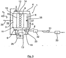
- the first exhaust gas recirculation line 4 is by means of a first Shut-off valve 2 and the second exhaust gas recirculation line 7 forming the bypass line can be shut off by means of a second shut-off valve 6.
- shut-off valves 2, 6 are coupled by means of a control and / or regulating device 18, by means of which an exhaust gas recirculation amount can be controlled or regulated by controlling the first and second shut-off valves 2, 6 as a function of defined exhaust gas recirculation parameters.
- the first exhaust gas recirculation line 4 is formed here substantially longer than the opposite second exhaust gas recirculation line 7, since the first exhaust gas recirculation line 4 extends not only from the exhaust side 16 on the air side 17 of the engine block 15 and the engine 9, as in approximately in the example case shown here in the second exhaust gas recirculation line 7 is the case, but extends the first exhaust gas recirculation line 4 also on the air side 17 of the engine 9 in the longitudinal direction x along the same to the air side end or mouth region of the second exhaust gas recirculation line 7, where the first exhaust gas recirculation line 4 and the second exhaust gas recirculation line 7 then in a Flanschstutzen 19 (in Fig. 1 and 2 dotted) pass over or merge. A concrete embodiment of this Flanschstutzens 19 is particularly in the Fig. 1 and 2 shown.
- a mixing point flange 19 passes through the first exhaust gas recirculation line 4 previously mentioned exhaust gas cooler 5, which extends here substantially over the entire length of the engine 9 and the engine block 15 and in which the exhaust gas can be cooled in a defined manner.
- the second exhaust gas recirculation line 7 is fixed as the exhaust gas cooler bypass line by means of a flange 20 at the flange 19 stably connected and connected.
- the exhaust gas cooler 5 is preferably operated as a full flow cooler, that is to say that the entire coolant flows through the exhaust gas cooler 5.
- the second exhaust gas recirculation line 7 in addition to be provided a thermal insulation, which is not shown here.
- an air line connection flange 21 is formed on the flange 19 downstream of the mouth areas of the first and second exhaust gas recirculation lines 4, 7, to which an air line 22 is flanged.
- a distributor pipe connection flange 24 is provided on the flange connection 19, downstream of the air line connection flange 21 and downstream of the mouth regions of the first and second exhaust gas recirculation lines 4, 7 and thus substantially in the region of an air admixing point 23 of the flange connection piece 19, to which an air distribution pipe 8 the internal combustion engine 9 is flanged.
- the air distribution pipe 8 is preferably flanged with a front flange region on the manifold connecting flange 24 and extends from there substantially over the entire length of the internal combustion engine 9 and der Motorblocks 15.
- the exhaust gas cooler 5 is substantially parallel to the air distribution pipe 8 and these two can be connected to each other, for example by means of a screw connection or the like. A uniform material and / or integral connection of the two components is conceivable.
- a temperature sensor 25 is further arranged on the air distribution pipe 8, which is signal-technically coupled to the control and / or regulating device 18 and by means of which the actual temperature in the air distribution pipe 8 can be detected.
- This actual temperature is compared by means of the control and / or regulating device with a stored in a map 26 of the control and / or regulating device 18, preferably load-dependent or load change-dependent desired temperature.
- a map 26 of the control and / or regulating device preferably load-dependent or load change-dependent desired temperature.
- the flow rate through the two shut-off valves 2, 6 is preferably controlled by their degree of opening.
- the two shut-off valves 2, 6, for example, displacement sensor, via which the control and / or regulating device 18 detects the opening degree of the shut-off valves 2, 6, and actuators 27, 28 (see Fig. 1 and 2 ) or actuators, via which the control and / or regulating device 18 actuates a valve actuating mechanism, not shown here in detail, of the two shut-off valves 2, 6.
- the control and / or regulating device 18 thus sets both the total recirculated exhaust gas quantity and the ratio of the respectively recirculated exhaust gas components via the two shut-off valves 2, 6.
- an exhaust gas recirculation device 1 a total of compact and little space occupying structure of an internal combustion engine 9 together with exhaust gas recirculation device 1, which is also suitable for cramped installation situations in engine compartments of vehicles, especially commercial vehicles, and by means of which also the formation of condensation on simple Way can be prevented or at least significantly reduced.
- a compressor 31 in particular a compressor of an exhaust gas turbocharger, not shown here, and a charge air cooler 32 and an air filter 33 is arranged.
Claims (11)
- Dispositif de recirculation de gaz d'échappement (1) pour un moteur à combustion interne d'un véhicule,
comprenant une première conduite de recirculation de gaz d'échappement (4) pouvant être bloquée au moyen d'un premier dispositif de blocage (2) et partant depuis un côté de gaz d'échappement (16) du moteur à combustion interne (9), laquelle revient, par le biais d'un refroidisseur de gaz d'échappement (5), jusqu'à un côté d'air (17) du moteur à combustion interne (9),
comprenant une conduite de dérivation en tant que deuxième conduite de recirculation de gaz d'échappement (7), pouvant être bloquée au moyen d'un deuxième dispositif de blocage (6) et contournant le refroidisseur de gaz d'échappement (5), au moyen de laquelle du gaz d'échappement peut être recirculé depuis le moteur à combustion interne (9) sans refroidissement jusqu'au côté d'air (17) du moteur à combustion interne (9), la première conduite de recirculation de gaz d'échappement (4) et la deuxième conduite de recirculation de gaz d'échappement (7) constituant une conduite de dérivation étant réunies en amont d'une zone d'addition d'air (23) au niveau de laquelle l'air guidé au moyen d'une conduite d'air (22) vers le côté d'air (17) du moteur à combustion interne (9) peut être mélangé au gaz d'échappement recirculé, et
comprenant un dispositif de commande et/ou de régulation (18), au moyen duquel la quantité de recirculation de gaz d'échappement peut être commandée et/ou régulée par commande du premier et/ou du deuxième dispositif de blocage (2, 6) en fonction de paramètres de recirculation de gaz d'échappement définis et/ou prédéfinis, caractérisé en ce que la première conduite de recirculation de gaz d'échappement (4) et la deuxième conduite de recirculation de gaz d'échappement (7) partent, au moyen de conduites séparées depuis le côté de gaz d'échappement (16) du moteur à combustion interne (9) et sont guidées de là respectivement au côté d'air opposé (17) du moteur à combustion interne (9), la première conduite de recirculation de gaz d'échappement (4) plus longue que la deuxième conduite de recirculation de gaz d'échappement (7) étant ensuite guidée plus loin le long du moteur à combustion interne (9) jusqu'à la région d'embouchure côté air de la deuxième conduite de recirculation de gaz d'échappement (7), où la première et la deuxième conduite de recirculation de gaz d'échappement (4, 7) sont réunies dans une région de mélange, la première et la deuxième conduite de recirculation de gaz d'échappement (4, 7) étant guidées à chaque fois dans la région et/ou le long des côtés frontaux opposés (12, 13) d'un bloc-moteur (15) du moteur à combustion interne (9) jusqu'au côté d'air (17) du moteur à combustion interne (9) et la région de mélange au niveau de laquelle sont réunies la première et la deuxième conduite de recirculation de gaz d'échappement (4, 7) étant formée par un raccord à bride (19) associé à une région de boîtier frontale du refroidisseur de gaz d'échappement (5), vu dans la direction d'étendue longitudinale du refroidisseur de gaz d'échappement (5), dans lequel raccord à bride débouche la première conduite de recirculation de gaz d'échappement (4) traversant le refroidisseur de gaz d'échappement (5) et auquel est raccordée la deuxième conduite de recirculation de gaz d'échappement (7). - Dispositif de recirculation de gaz d'échappement selon la revendication 1, caractérisé en ce que la première conduite de recirculation de gaz d'échappement (4) et la deuxième conduite de recirculation de gaz d'échappement (7) partent d'un collecteur de gaz d'échappement (3) au moyen de conduites séparées.
- Dispositif de recirculation de gaz d'échappement selon la revendication 2, caractérisé en ce que la première conduite de recirculation de gaz d'échappement (4) part depuis une première région d'extrémité du collecteur de gaz d'échappement (10), vue dans la direction longitudinale d'un collecteur de gaz d'échappement (3) du moteur à combustion interne (9), et en ce que la deuxième conduite de recirculation de gaz d'échappement (7) part depuis une deuxième région d'extrémité du collecteur de gaz d'échappement (11), vue dans la direction longitudinale d'un collecteur de gaz d'échappement (3) du moteur à combustion interne (9), qui est opposée à la première région d'extrémité du collecteur de gaz d'échappement (10).
- Dispositif de recirculation de gaz d'échappement selon l'une quelconque des revendications précédentes, caractérisé en ce que le refroidisseur de gaz d'échappement (5) s'étend essentiellement sur toute la longueur du moteur à combustion interne (9).
- Dispositif de recirculation de gaz d'échappement selon l'une quelconque des revendications précédentes, caractérisé en ce que le raccord à bride (19) auquel est raccordée la deuxième conduite de recirculation de gaz d'échappement (7), est raccordé au moyen d'une connexion à bride (20).
- Dispositif de recirculation de gaz d'échappement selon l'une quelconque des revendications précédentes, caractérisé en ce que la première conduite de recirculation de gaz d'échappement (4) se prolonge, venue de matière et/ou d'une seule pièce, dans le raccord à bride (19) ou en ce que le raccord à bride (19) est un composant séparé qui est connecté à la première conduite de recirculation de gaz d'échappement (4) et/ou au refroidisseur de gaz d'échappement (5), en particulier par engagement par correspondance de formes, et/ou par force et/ou par liaison de matière.
- Dispositif de recirculation de gaz d'échappement selon l'une quelconque des revendications précédentes, caractérisé en ce qu'au niveau du raccord à bride (19), en aval des régions d'embouchure de la première et de la deuxième conduite de recirculation de gaz d'échappement (4, 7), est réalisée une bride de raccordement de conduite d'air (21) à laquelle est bridée la conduite d'air (22), et en ce qu'au niveau du raccord à bride (19), en amont de la bride de raccordement de conduite d'air (21) et en aval des régions d'embouchure de la première et de la deuxième conduite de recirculation de gaz d'échappement (4, 7), et par conséquent essentiellement dans la région de la zone d'addition d'air (23), est en outre prévue une bride de raccordement de tube distributeur (24), à laquelle est bridé un tube distributeur d'air (8) du moteur à combustion interne (9).
- Dispositif de recirculation de gaz d'échappement selon la revendication 7, caractérisé en ce que le tube distributeur d'air (8) est bridé à la bride de raccordement de tube distributeur (24) par une région de bride frontale, et s'étend à partir de là sur sensiblement la longueur totale du moteur à combustion interne (9).
- Dispositif de recirculation de gaz d'échappement selon l'une quelconque des revendications précédentes, caractérisé en ce que le refroidisseur de gaz d'échappement (5) s'étendant essentiellement parallèlement au tube distributeur d'air (8) et/ou en ce que le refroidisseur de gaz d'échappement (5) est connecté au tube distributeur d'air (8), en particulier lui est connecté venu de matière et/ou d'une seule pièce ou lui est connecté par engagement par correspondance de formes et/ou par force et/ou par liaison de matière.
- Dispositif de recirculation de gaz d'échappement selon l'une quelconque des revendications précédentes, caractérisé en ce qu'au moins un capteur de température (25) est disposé au niveau du tube distributeur d'air (8), lequel est accouplé au dispositif de commande et/ou de régulation (18) par une technique de transmission des signaux et détecte la température réelle dans le tube distributeur d'air (8), en ce que le dispositif de commande et/ou de régulation (18) compare la température réelle détectée au moyen de l'au moins un capteur de température (25) avec une température de consigne définie et/ou prédéfinie, en particulier avec une température de consigne dépendant de la charge et/ou dépendant du changement de charge, consignée dans un champ caractéristique (26) du dispositif de commande et/ou de régulation (18), et en cas d'écart entre la température réelle et la température de consigne, commande le premier et/ou le deuxième dispositif de blocage (2, 62) de telle sorte qu'une quantité de gaz d'échappement ajustant la température de consigne dans le tube distributeur d'air (8) puisse être recirculée par le biais de la première et/ou de la deuxième conduite de recirculation de gaz d'échappement (4, 7).
- Dispositif de recirculation de gaz d'échappement selon l'une quelconque des revendications précédentes, caractérisé en ce que dans la conduite d'air (22), en amont de la zone d'addition d'air (23), sont disposés un compresseur (31), en particulier un compresseur d'un turbocompresseur à gaz d'échappement, et/ou un refroidisseur d'air de suralimentation (32) et/ou un filtre à air (33).
Applications Claiming Priority (1)
| Application Number | Priority Date | Filing Date | Title |
|---|---|---|---|
| DE102011109264A DE102011109264A1 (de) | 2011-08-03 | 2011-08-03 | Abgasrückführeinrichtung für eine Brennkraftmaschine eines Fahrzeuges sowie Verfahren zum Betreiben einer Abgasrückführeinrichtung |
Publications (3)
| Publication Number | Publication Date |
|---|---|
| EP2562407A2 EP2562407A2 (fr) | 2013-02-27 |
| EP2562407A3 EP2562407A3 (fr) | 2013-06-19 |
| EP2562407B1 true EP2562407B1 (fr) | 2016-04-06 |
Family
ID=46581700
Family Applications (1)
| Application Number | Title | Priority Date | Filing Date |
|---|---|---|---|
| EP12005199.0A Active EP2562407B1 (fr) | 2011-08-03 | 2012-07-14 | Dispositif de récirculation des gaz d'échappement d'un moteur à combustion interne d'un véhicule et procédé de fonctionnement d'un dispositif de récirculation de gaz d'échappement |
Country Status (5)
| Country | Link |
|---|---|
| EP (1) | EP2562407B1 (fr) |
| CN (1) | CN102913344B (fr) |
| BR (1) | BR102012019403B1 (fr) |
| DE (1) | DE102011109264A1 (fr) |
| RU (1) | RU2602021C2 (fr) |
Families Citing this family (2)
| Publication number | Priority date | Publication date | Assignee | Title |
|---|---|---|---|---|
| JP6255318B2 (ja) * | 2014-08-01 | 2017-12-27 | 本田技研工業株式会社 | ユニフロー2ストロークエンジン |
| DE102016113555B4 (de) * | 2016-07-22 | 2020-03-12 | Pierburg Gmbh | Abgas-System für eine Verbrennungskraftmaschine |
Family Cites Families (11)
| Publication number | Priority date | Publication date | Assignee | Title |
|---|---|---|---|---|
| US5617726A (en) | 1995-03-31 | 1997-04-08 | Cummins Engine Company, Inc. | Cooled exhaust gas recirculation system with load and ambient bypasses |
| DE19622891C2 (de) * | 1996-06-07 | 1998-04-09 | Ranco Inc | Abgasrückführungssystem |
| SE521713C2 (sv) * | 1998-11-09 | 2003-12-02 | Stt Emtec Ab | Förfarande och anordning för ett EGR-system, samt dylik ventil |
| DE10011954A1 (de) * | 2000-03-11 | 2001-09-13 | Modine Mfg Co | Abgaswärmetauscher in einer Abgasrückführungsanordnung |
| GB0018406D0 (en) * | 2000-07-28 | 2000-09-13 | Serck Heat Transfer Limited | EGR bypass tube cooler |
| US6367256B1 (en) * | 2001-03-26 | 2002-04-09 | Detroit Diesel Corporation | Exhaust gas recirculation with condensation control |
| JP2006037773A (ja) * | 2004-07-23 | 2006-02-09 | Denso Corp | 排気ガス再循環制御装置 |
| FR2902151B1 (fr) * | 2006-06-07 | 2008-08-08 | Peugeot Citroen Automobiles Sa | Moteur a combustion interne ayant un circuit de recirculation des gaz d'echappement |
| WO2008048909A2 (fr) * | 2006-10-18 | 2008-04-24 | Eden Innovations Ltd. Dba/Aka Brehon Energy Plc | Système et procédé de combustion stœchiométrique pour moteurs à combustion interne alimentés à l'hydrogène |
| EP2278148A1 (fr) * | 2009-06-23 | 2011-01-26 | Ford Global Technologies, LLC | Moteur a combustion interne avec recirculation de gaz d'échappement et procédé de contrôle d'un tel moteur |
| US8230843B2 (en) * | 2009-07-30 | 2012-07-31 | Ford Global Technologies, Llc | Cooler bypass to reduce condensate in a low-pressure EGR system |
-
2011
- 2011-08-03 DE DE102011109264A patent/DE102011109264A1/de not_active Withdrawn
-
2012
- 2012-07-14 EP EP12005199.0A patent/EP2562407B1/fr active Active
- 2012-08-02 RU RU2012133243/06A patent/RU2602021C2/ru active
- 2012-08-02 BR BR102012019403-1A patent/BR102012019403B1/pt active IP Right Grant
- 2012-08-03 CN CN201210274897.8A patent/CN102913344B/zh active Active
Also Published As
| Publication number | Publication date |
|---|---|
| BR102012019403A2 (pt) | 2013-11-26 |
| RU2602021C2 (ru) | 2016-11-10 |
| CN102913344A (zh) | 2013-02-06 |
| EP2562407A3 (fr) | 2013-06-19 |
| RU2012133243A (ru) | 2014-02-10 |
| BR102012019403B1 (pt) | 2021-02-09 |
| CN102913344B (zh) | 2016-12-21 |
| EP2562407A2 (fr) | 2013-02-27 |
| DE102011109264A1 (de) | 2013-02-07 |
Similar Documents
| Publication | Publication Date | Title |
|---|---|---|
| EP2161438B1 (fr) | Système de récirculation de gaz d'échappement d'un moteur à combustion interne et procédé de récirculation de gaz d'échappement d'un moteur à combustion interne | |
| DE102009015656B4 (de) | Modulare Abgasrückführungsanlage, Motorsystem und Verfahren zum Kühlen eines Abgasrückführungsgasstroms | |
| EP1496221A2 (fr) | Dispositif permettant l'alimentation en melange gazeux dans la conduite d'admission d'un moteur à combustion interne | |
| DE102007049336B4 (de) | Multifunktionales Modul zur Anbringung an einer Verbrennungskraftmaschine und zur Führung von Fluiden | |
| EP2161429B1 (fr) | Module d'aspiration pour un moteur à combustion | |
| DE102008048912B4 (de) | Abgasanlage und Abgasventil zur Steuerung eines Volumenstroms von Abgas sowie ein Verfahren zur Steuerung eines Volumenstroms | |
| EP2305991B1 (fr) | Moteur à combustion interne doté d'une turbosoufflante de gaz d'échappement et d'un système de refoulement des gaz d'échappement | |
| EP3027881B1 (fr) | Module d'aspiration destiné à un moteur à combustion interne | |
| DE102017118455A1 (de) | Abgasnachbehandlungssystem für einen Verbrennungsmotor und Verfahren zur Abgasnachbehandlung eines Verbrennungsmotors | |
| DE102013206690A1 (de) | Brennkraftmaschine mit Ladeluftkühler und Abgasrückführung und Verfahren zum Herstellen einer derartigen Brennkraftmaschine | |
| EP2562407B1 (fr) | Dispositif de récirculation des gaz d'échappement d'un moteur à combustion interne d'un véhicule et procédé de fonctionnement d'un dispositif de récirculation de gaz d'échappement | |
| DE102011013496A1 (de) | Verbrennungskraftmaschine für einen Kraftwagen | |
| DE102008047079A1 (de) | Ansaugmodul für einen Verbrennungsmotor | |
| DE102007019089A1 (de) | Abgaswärmetauscher, Abgaswärmetauschersystem, Brennkraftmotor und Verfahren zum Behandeln von Abgasen eines Brennkraftmotors | |
| AT523180B1 (de) | Brennkraftmaschine mit mehreren zylindern | |
| DE102004013206B4 (de) | Variable Kühlvorrichtung für zur Saugseite eines aufgeladenen Verbrennungsmotors rückgeführtes Abgas | |
| EP2737195B1 (fr) | Moteur à combustion interne suralimenté | |
| EP3301290B1 (fr) | Système à canaux pour un moteur à combustion interne | |
| WO2007028464A1 (fr) | Dispositif de commande d'un flux de gaz d'echappement | |
| DE102004025185B4 (de) | Luftansaugkanalsystem für Verbrennungskraftmaschinen | |
| DE102018208983A1 (de) | Anordnung zum Rezirkulieren von Abgas | |
| DE102010036298B4 (de) | Brennkraftmaschine mit einer eine Prallhülse aufweisenden Abgasleitung | |
| DE102006017149A1 (de) | Abgasrückführsystem für eine Brennkraftmaschine | |
| DE102016200361B4 (de) | Reduktion von Kondensat in einem Abgasrückführungssystem | |
| DE102022130345A1 (de) | Gasmischvorrichtung für Abgasrückführsysteme von Verbrennungsmotoren |
Legal Events
| Date | Code | Title | Description |
|---|---|---|---|
| PUAI | Public reference made under article 153(3) epc to a published international application that has entered the european phase |
Free format text: ORIGINAL CODE: 0009012 |
|
| AK | Designated contracting states |
Kind code of ref document: A2 Designated state(s): AL AT BE BG CH CY CZ DE DK EE ES FI FR GB GR HR HU IE IS IT LI LT LU LV MC MK MT NL NO PL PT RO RS SE SI SK SM TR |
|
| AX | Request for extension of the european patent |
Extension state: BA ME |
|
| PUAL | Search report despatched |
Free format text: ORIGINAL CODE: 0009013 |
|
| AK | Designated contracting states |
Kind code of ref document: A3 Designated state(s): AL AT BE BG CH CY CZ DE DK EE ES FI FR GB GR HR HU IE IS IT LI LT LU LV MC MK MT NL NO PL PT RO RS SE SI SK SM TR |
|
| AX | Request for extension of the european patent |
Extension state: BA ME |
|
| RIC1 | Information provided on ipc code assigned before grant |
Ipc: F02M 25/07 20060101AFI20130510BHEP Ipc: F02D 41/00 20060101ALI20130510BHEP |
|
| 17P | Request for examination filed |
Effective date: 20140215 |
|
| 17Q | First examination report despatched |
Effective date: 20141104 |
|
| GRAP | Despatch of communication of intention to grant a patent |
Free format text: ORIGINAL CODE: EPIDOSNIGR1 |
|
| INTG | Intention to grant announced |
Effective date: 20151203 |
|
| GRAS | Grant fee paid |
Free format text: ORIGINAL CODE: EPIDOSNIGR3 |
|
| REG | Reference to a national code |
Ref country code: DE Ref legal event code: R079 Ref document number: 502012006542 Country of ref document: DE Free format text: PREVIOUS MAIN CLASS: F02M0025070000 Ipc: F02M0026000000 |
|
| GRAA | (expected) grant |
Free format text: ORIGINAL CODE: 0009210 |
|
| RIC1 | Information provided on ipc code assigned before grant |
Ipc: F02D 41/00 20060101ALI20160210BHEP Ipc: F02M 26/00 20160101AFI20160210BHEP |
|
| AK | Designated contracting states |
Kind code of ref document: B1 Designated state(s): AL AT BE BG CH CY CZ DE DK EE ES FI FR GB GR HR HU IE IS IT LI LT LU LV MC MK MT NL NO PL PT RO RS SE SI SK SM TR |
|
| REG | Reference to a national code |
Ref country code: GB Ref legal event code: FG4D Free format text: NOT ENGLISH |
|
| REG | Reference to a national code |
Ref country code: AT Ref legal event code: REF Ref document number: 788103 Country of ref document: AT Kind code of ref document: T Effective date: 20160415 Ref country code: CH Ref legal event code: EP |
|
| REG | Reference to a national code |
Ref country code: IE Ref legal event code: FG4D Free format text: LANGUAGE OF EP DOCUMENT: GERMAN |
|
| REG | Reference to a national code |
Ref country code: DE Ref legal event code: R096 Ref document number: 502012006542 Country of ref document: DE |
|
| REG | Reference to a national code |
Ref country code: NL Ref legal event code: FP |
|
| REG | Reference to a national code |
Ref country code: SE Ref legal event code: TRGR |
|
| REG | Reference to a national code |
Ref country code: FR Ref legal event code: PLFP Year of fee payment: 5 |
|
| REG | Reference to a national code |
Ref country code: LT Ref legal event code: MG4D |
|
| PG25 | Lapsed in a contracting state [announced via postgrant information from national office to epo] |
Ref country code: PL Free format text: LAPSE BECAUSE OF FAILURE TO SUBMIT A TRANSLATION OF THE DESCRIPTION OR TO PAY THE FEE WITHIN THE PRESCRIBED TIME-LIMIT Effective date: 20160406 Ref country code: FI Free format text: LAPSE BECAUSE OF FAILURE TO SUBMIT A TRANSLATION OF THE DESCRIPTION OR TO PAY THE FEE WITHIN THE PRESCRIBED TIME-LIMIT Effective date: 20160406 Ref country code: IS Free format text: LAPSE BECAUSE OF FAILURE TO SUBMIT A TRANSLATION OF THE DESCRIPTION OR TO PAY THE FEE WITHIN THE PRESCRIBED TIME-LIMIT Effective date: 20160806 Ref country code: NO Free format text: LAPSE BECAUSE OF FAILURE TO SUBMIT A TRANSLATION OF THE DESCRIPTION OR TO PAY THE FEE WITHIN THE PRESCRIBED TIME-LIMIT Effective date: 20160706 Ref country code: LT Free format text: LAPSE BECAUSE OF FAILURE TO SUBMIT A TRANSLATION OF THE DESCRIPTION OR TO PAY THE FEE WITHIN THE PRESCRIBED TIME-LIMIT Effective date: 20160406 |
|
| PG25 | Lapsed in a contracting state [announced via postgrant information from national office to epo] |
Ref country code: RS Free format text: LAPSE BECAUSE OF FAILURE TO SUBMIT A TRANSLATION OF THE DESCRIPTION OR TO PAY THE FEE WITHIN THE PRESCRIBED TIME-LIMIT Effective date: 20160406 Ref country code: PT Free format text: LAPSE BECAUSE OF FAILURE TO SUBMIT A TRANSLATION OF THE DESCRIPTION OR TO PAY THE FEE WITHIN THE PRESCRIBED TIME-LIMIT Effective date: 20160808 Ref country code: GR Free format text: LAPSE BECAUSE OF FAILURE TO SUBMIT A TRANSLATION OF THE DESCRIPTION OR TO PAY THE FEE WITHIN THE PRESCRIBED TIME-LIMIT Effective date: 20160707 Ref country code: HR Free format text: LAPSE BECAUSE OF FAILURE TO SUBMIT A TRANSLATION OF THE DESCRIPTION OR TO PAY THE FEE WITHIN THE PRESCRIBED TIME-LIMIT Effective date: 20160406 Ref country code: LV Free format text: LAPSE BECAUSE OF FAILURE TO SUBMIT A TRANSLATION OF THE DESCRIPTION OR TO PAY THE FEE WITHIN THE PRESCRIBED TIME-LIMIT Effective date: 20160406 Ref country code: ES Free format text: LAPSE BECAUSE OF FAILURE TO SUBMIT A TRANSLATION OF THE DESCRIPTION OR TO PAY THE FEE WITHIN THE PRESCRIBED TIME-LIMIT Effective date: 20160406 |
|
| PG25 | Lapsed in a contracting state [announced via postgrant information from national office to epo] |
Ref country code: BE Free format text: LAPSE BECAUSE OF NON-PAYMENT OF DUE FEES Effective date: 20160731 |
|
| REG | Reference to a national code |
Ref country code: DE Ref legal event code: R097 Ref document number: 502012006542 Country of ref document: DE |
|
| PG25 | Lapsed in a contracting state [announced via postgrant information from national office to epo] |
Ref country code: CZ Free format text: LAPSE BECAUSE OF FAILURE TO SUBMIT A TRANSLATION OF THE DESCRIPTION OR TO PAY THE FEE WITHIN THE PRESCRIBED TIME-LIMIT Effective date: 20160406 Ref country code: RO Free format text: LAPSE BECAUSE OF FAILURE TO SUBMIT A TRANSLATION OF THE DESCRIPTION OR TO PAY THE FEE WITHIN THE PRESCRIBED TIME-LIMIT Effective date: 20160406 Ref country code: SK Free format text: LAPSE BECAUSE OF FAILURE TO SUBMIT A TRANSLATION OF THE DESCRIPTION OR TO PAY THE FEE WITHIN THE PRESCRIBED TIME-LIMIT Effective date: 20160406 Ref country code: EE Free format text: LAPSE BECAUSE OF FAILURE TO SUBMIT A TRANSLATION OF THE DESCRIPTION OR TO PAY THE FEE WITHIN THE PRESCRIBED TIME-LIMIT Effective date: 20160406 Ref country code: DK Free format text: LAPSE BECAUSE OF FAILURE TO SUBMIT A TRANSLATION OF THE DESCRIPTION OR TO PAY THE FEE WITHIN THE PRESCRIBED TIME-LIMIT Effective date: 20160406 |
|
| PLBE | No opposition filed within time limit |
Free format text: ORIGINAL CODE: 0009261 |
|
| STAA | Information on the status of an ep patent application or granted ep patent |
Free format text: STATUS: NO OPPOSITION FILED WITHIN TIME LIMIT |
|
| PG25 | Lapsed in a contracting state [announced via postgrant information from national office to epo] |
Ref country code: SM Free format text: LAPSE BECAUSE OF FAILURE TO SUBMIT A TRANSLATION OF THE DESCRIPTION OR TO PAY THE FEE WITHIN THE PRESCRIBED TIME-LIMIT Effective date: 20160406 |
|
| REG | Reference to a national code |
Ref country code: CH Ref legal event code: PL |
|
| 26N | No opposition filed |
Effective date: 20170110 |
|
| GBPC | Gb: european patent ceased through non-payment of renewal fee |
Effective date: 20160714 |
|
| PG25 | Lapsed in a contracting state [announced via postgrant information from national office to epo] |
Ref country code: MC Free format text: LAPSE BECAUSE OF FAILURE TO SUBMIT A TRANSLATION OF THE DESCRIPTION OR TO PAY THE FEE WITHIN THE PRESCRIBED TIME-LIMIT Effective date: 20160406 |
|
| PG25 | Lapsed in a contracting state [announced via postgrant information from national office to epo] |
Ref country code: CH Free format text: LAPSE BECAUSE OF NON-PAYMENT OF DUE FEES Effective date: 20160731 Ref country code: LI Free format text: LAPSE BECAUSE OF NON-PAYMENT OF DUE FEES Effective date: 20160731 |
|
| REG | Reference to a national code |
Ref country code: IE Ref legal event code: MM4A |
|
| PG25 | Lapsed in a contracting state [announced via postgrant information from national office to epo] |
Ref country code: GB Free format text: LAPSE BECAUSE OF NON-PAYMENT OF DUE FEES Effective date: 20160714 Ref country code: SI Free format text: LAPSE BECAUSE OF FAILURE TO SUBMIT A TRANSLATION OF THE DESCRIPTION OR TO PAY THE FEE WITHIN THE PRESCRIBED TIME-LIMIT Effective date: 20160406 |
|
| REG | Reference to a national code |
Ref country code: FR Ref legal event code: PLFP Year of fee payment: 6 |
|
| PG25 | Lapsed in a contracting state [announced via postgrant information from national office to epo] |
Ref country code: IE Free format text: LAPSE BECAUSE OF NON-PAYMENT OF DUE FEES Effective date: 20160714 |
|
| PG25 | Lapsed in a contracting state [announced via postgrant information from national office to epo] |
Ref country code: LU Free format text: LAPSE BECAUSE OF NON-PAYMENT OF DUE FEES Effective date: 20160714 |
|
| PG25 | Lapsed in a contracting state [announced via postgrant information from national office to epo] |
Ref country code: HU Free format text: LAPSE BECAUSE OF FAILURE TO SUBMIT A TRANSLATION OF THE DESCRIPTION OR TO PAY THE FEE WITHIN THE PRESCRIBED TIME-LIMIT; INVALID AB INITIO Effective date: 20120714 Ref country code: CY Free format text: LAPSE BECAUSE OF FAILURE TO SUBMIT A TRANSLATION OF THE DESCRIPTION OR TO PAY THE FEE WITHIN THE PRESCRIBED TIME-LIMIT Effective date: 20160406 |
|
| PG25 | Lapsed in a contracting state [announced via postgrant information from national office to epo] |
Ref country code: TR Free format text: LAPSE BECAUSE OF FAILURE TO SUBMIT A TRANSLATION OF THE DESCRIPTION OR TO PAY THE FEE WITHIN THE PRESCRIBED TIME-LIMIT Effective date: 20160406 Ref country code: MT Free format text: LAPSE BECAUSE OF FAILURE TO SUBMIT A TRANSLATION OF THE DESCRIPTION OR TO PAY THE FEE WITHIN THE PRESCRIBED TIME-LIMIT Effective date: 20160406 Ref country code: MK Free format text: LAPSE BECAUSE OF FAILURE TO SUBMIT A TRANSLATION OF THE DESCRIPTION OR TO PAY THE FEE WITHIN THE PRESCRIBED TIME-LIMIT Effective date: 20160406 |
|
| REG | Reference to a national code |
Ref country code: FR Ref legal event code: PLFP Year of fee payment: 7 |
|
| PG25 | Lapsed in a contracting state [announced via postgrant information from national office to epo] |
Ref country code: BG Free format text: LAPSE BECAUSE OF FAILURE TO SUBMIT A TRANSLATION OF THE DESCRIPTION OR TO PAY THE FEE WITHIN THE PRESCRIBED TIME-LIMIT Effective date: 20160406 |
|
| REG | Reference to a national code |
Ref country code: AT Ref legal event code: MM01 Ref document number: 788103 Country of ref document: AT Kind code of ref document: T Effective date: 20170714 |
|
| PG25 | Lapsed in a contracting state [announced via postgrant information from national office to epo] |
Ref country code: AL Free format text: LAPSE BECAUSE OF FAILURE TO SUBMIT A TRANSLATION OF THE DESCRIPTION OR TO PAY THE FEE WITHIN THE PRESCRIBED TIME-LIMIT Effective date: 20160406 |
|
| PG25 | Lapsed in a contracting state [announced via postgrant information from national office to epo] |
Ref country code: AT Free format text: LAPSE BECAUSE OF NON-PAYMENT OF DUE FEES Effective date: 20170714 |
|
| REG | Reference to a national code |
Ref country code: DE Ref legal event code: R081 Ref document number: 502012006542 Country of ref document: DE Owner name: MAN TRUCK & BUS SE, DE Free format text: FORMER OWNER: MAN TRUCK & BUS AG, 80995 MUENCHEN, DE |
|
| PGFP | Annual fee paid to national office [announced via postgrant information from national office to epo] |
Ref country code: SE Payment date: 20230317 Year of fee payment: 12 |
|
| PGFP | Annual fee paid to national office [announced via postgrant information from national office to epo] |
Ref country code: NL Payment date: 20230726 Year of fee payment: 12 |
|
| PGFP | Annual fee paid to national office [announced via postgrant information from national office to epo] |
Ref country code: IT Payment date: 20230721 Year of fee payment: 12 |
|
| PGFP | Annual fee paid to national office [announced via postgrant information from national office to epo] |
Ref country code: FR Payment date: 20230725 Year of fee payment: 12 Ref country code: DE Payment date: 20230726 Year of fee payment: 12 |