EP2562407B1 - Exhaust gas recirculation device for a combustion engine of a vehicle and method for operating an exhaust gas recirculation device - Google Patents
Exhaust gas recirculation device for a combustion engine of a vehicle and method for operating an exhaust gas recirculation device Download PDFInfo
- Publication number
- EP2562407B1 EP2562407B1 EP12005199.0A EP12005199A EP2562407B1 EP 2562407 B1 EP2562407 B1 EP 2562407B1 EP 12005199 A EP12005199 A EP 12005199A EP 2562407 B1 EP2562407 B1 EP 2562407B1
- Authority
- EP
- European Patent Office
- Prior art keywords
- exhaust
- gas recirculation
- air
- exhaust gas
- combustion engine
- Prior art date
- Legal status (The legal status is an assumption and is not a legal conclusion. Google has not performed a legal analysis and makes no representation as to the accuracy of the status listed.)
- Active
Links
- 238000002485 combustion reaction Methods 0.000 title claims description 48
- 238000000034 method Methods 0.000 title description 5
- 230000001105 regulatory effect Effects 0.000 claims description 22
- 238000002156 mixing Methods 0.000 claims description 10
- 238000011144 upstream manufacturing Methods 0.000 claims description 8
- 230000001419 dependent effect Effects 0.000 claims description 7
- 239000007789 gas Substances 0.000 description 137
- 238000009826 distribution Methods 0.000 description 16
- 238000010276 construction Methods 0.000 description 6
- 230000015572 biosynthetic process Effects 0.000 description 5
- 238000009833 condensation Methods 0.000 description 5
- 230000005494 condensation Effects 0.000 description 5
- QAOWNCQODCNURD-UHFFFAOYSA-N Sulfuric acid Chemical compound OS(O)(=O)=O QAOWNCQODCNURD-UHFFFAOYSA-N 0.000 description 4
- 238000001816 cooling Methods 0.000 description 4
- 239000000463 material Substances 0.000 description 4
- NINIDFKCEFEMDL-UHFFFAOYSA-N Sulfur Chemical compound [S] NINIDFKCEFEMDL-UHFFFAOYSA-N 0.000 description 3
- 230000001276 controlling effect Effects 0.000 description 3
- 239000002826 coolant Substances 0.000 description 3
- 239000000446 fuel Substances 0.000 description 3
- 229910052717 sulfur Inorganic materials 0.000 description 3
- 239000011593 sulfur Substances 0.000 description 3
- 238000009434 installation Methods 0.000 description 2
- 239000000498 cooling water Substances 0.000 description 1
- 238000010586 diagram Methods 0.000 description 1
- 238000006073 displacement reaction Methods 0.000 description 1
- 230000000694 effects Effects 0.000 description 1
- 238000005516 engineering process Methods 0.000 description 1
- 238000002474 experimental method Methods 0.000 description 1
- 238000009413 insulation Methods 0.000 description 1
- 230000010354 integration Effects 0.000 description 1
- 238000004519 manufacturing process Methods 0.000 description 1
- 239000000203 mixture Substances 0.000 description 1
- 239000002245 particle Substances 0.000 description 1
- 238000004886 process control Methods 0.000 description 1
- 238000011112 process operation Methods 0.000 description 1
- 238000001228 spectrum Methods 0.000 description 1
Images


Classifications
-
- F—MECHANICAL ENGINEERING; LIGHTING; HEATING; WEAPONS; BLASTING
- F02—COMBUSTION ENGINES; HOT-GAS OR COMBUSTION-PRODUCT ENGINE PLANTS
- F02M—SUPPLYING COMBUSTION ENGINES IN GENERAL WITH COMBUSTIBLE MIXTURES OR CONSTITUENTS THEREOF
- F02M26/00—Engine-pertinent apparatus for adding exhaust gases to combustion-air, main fuel or fuel-air mixture, e.g. by exhaust gas recirculation [EGR] systems
- F02M26/13—Arrangement or layout of EGR passages, e.g. in relation to specific engine parts or for incorporation of accessories
- F02M26/22—Arrangement or layout of EGR passages, e.g. in relation to specific engine parts or for incorporation of accessories with coolers in the recirculation passage
- F02M26/23—Layout, e.g. schematics
- F02M26/25—Layout, e.g. schematics with coolers having bypasses
-
- F—MECHANICAL ENGINEERING; LIGHTING; HEATING; WEAPONS; BLASTING
- F02—COMBUSTION ENGINES; HOT-GAS OR COMBUSTION-PRODUCT ENGINE PLANTS
- F02D—CONTROLLING COMBUSTION ENGINES
- F02D41/00—Electrical control of supply of combustible mixture or its constituents
- F02D41/0025—Controlling engines characterised by use of non-liquid fuels, pluralities of fuels, or non-fuel substances added to the combustible mixtures
- F02D41/0047—Controlling exhaust gas recirculation [EGR]
- F02D41/005—Controlling exhaust gas recirculation [EGR] according to engine operating conditions
- F02D41/0052—Feedback control of engine parameters, e.g. for control of air/fuel ratio or intake air amount
-
- F—MECHANICAL ENGINEERING; LIGHTING; HEATING; WEAPONS; BLASTING
- F02—COMBUSTION ENGINES; HOT-GAS OR COMBUSTION-PRODUCT ENGINE PLANTS
- F02M—SUPPLYING COMBUSTION ENGINES IN GENERAL WITH COMBUSTIBLE MIXTURES OR CONSTITUENTS THEREOF
- F02M26/00—Engine-pertinent apparatus for adding exhaust gases to combustion-air, main fuel or fuel-air mixture, e.g. by exhaust gas recirculation [EGR] systems
- F02M26/13—Arrangement or layout of EGR passages, e.g. in relation to specific engine parts or for incorporation of accessories
- F02M26/22—Arrangement or layout of EGR passages, e.g. in relation to specific engine parts or for incorporation of accessories with coolers in the recirculation passage
- F02M26/33—Arrangement or layout of EGR passages, e.g. in relation to specific engine parts or for incorporation of accessories with coolers in the recirculation passage controlling the temperature of the recirculated gases
-
- F—MECHANICAL ENGINEERING; LIGHTING; HEATING; WEAPONS; BLASTING
- F02—COMBUSTION ENGINES; HOT-GAS OR COMBUSTION-PRODUCT ENGINE PLANTS
- F02M—SUPPLYING COMBUSTION ENGINES IN GENERAL WITH COMBUSTIBLE MIXTURES OR CONSTITUENTS THEREOF
- F02M26/00—Engine-pertinent apparatus for adding exhaust gases to combustion-air, main fuel or fuel-air mixture, e.g. by exhaust gas recirculation [EGR] systems
- F02M26/13—Arrangement or layout of EGR passages, e.g. in relation to specific engine parts or for incorporation of accessories
- F02M26/41—Arrangement or layout of EGR passages, e.g. in relation to specific engine parts or for incorporation of accessories characterised by the arrangement of the recirculation passage in relation to the engine, e.g. to cylinder heads, liners, spark plugs or manifolds; characterised by the arrangement of the recirculation passage in relation to specially adapted combustion chambers
-
- F—MECHANICAL ENGINEERING; LIGHTING; HEATING; WEAPONS; BLASTING
- F02—COMBUSTION ENGINES; HOT-GAS OR COMBUSTION-PRODUCT ENGINE PLANTS
- F02M—SUPPLYING COMBUSTION ENGINES IN GENERAL WITH COMBUSTIBLE MIXTURES OR CONSTITUENTS THEREOF
- F02M26/00—Engine-pertinent apparatus for adding exhaust gases to combustion-air, main fuel or fuel-air mixture, e.g. by exhaust gas recirculation [EGR] systems
- F02M26/45—Sensors specially adapted for EGR systems
- F02M26/46—Sensors specially adapted for EGR systems for determining the characteristics of gases, e.g. composition
- F02M26/47—Sensors specially adapted for EGR systems for determining the characteristics of gases, e.g. composition the characteristics being temperatures, pressures or flow rates
-
- F—MECHANICAL ENGINEERING; LIGHTING; HEATING; WEAPONS; BLASTING
- F02—COMBUSTION ENGINES; HOT-GAS OR COMBUSTION-PRODUCT ENGINE PLANTS
- F02M—SUPPLYING COMBUSTION ENGINES IN GENERAL WITH COMBUSTIBLE MIXTURES OR CONSTITUENTS THEREOF
- F02M26/00—Engine-pertinent apparatus for adding exhaust gases to combustion-air, main fuel or fuel-air mixture, e.g. by exhaust gas recirculation [EGR] systems
- F02M26/50—Arrangements or methods for preventing or reducing deposits, corrosion or wear caused by impurities
-
- F—MECHANICAL ENGINEERING; LIGHTING; HEATING; WEAPONS; BLASTING
- F02—COMBUSTION ENGINES; HOT-GAS OR COMBUSTION-PRODUCT ENGINE PLANTS
- F02M—SUPPLYING COMBUSTION ENGINES IN GENERAL WITH COMBUSTIBLE MIXTURES OR CONSTITUENTS THEREOF
- F02M26/00—Engine-pertinent apparatus for adding exhaust gases to combustion-air, main fuel or fuel-air mixture, e.g. by exhaust gas recirculation [EGR] systems
- F02M26/13—Arrangement or layout of EGR passages, e.g. in relation to specific engine parts or for incorporation of accessories
- F02M26/17—Arrangement or layout of EGR passages, e.g. in relation to specific engine parts or for incorporation of accessories in relation to the intake system
-
- Y—GENERAL TAGGING OF NEW TECHNOLOGICAL DEVELOPMENTS; GENERAL TAGGING OF CROSS-SECTIONAL TECHNOLOGIES SPANNING OVER SEVERAL SECTIONS OF THE IPC; TECHNICAL SUBJECTS COVERED BY FORMER USPC CROSS-REFERENCE ART COLLECTIONS [XRACs] AND DIGESTS
- Y02—TECHNOLOGIES OR APPLICATIONS FOR MITIGATION OR ADAPTATION AGAINST CLIMATE CHANGE
- Y02T—CLIMATE CHANGE MITIGATION TECHNOLOGIES RELATED TO TRANSPORTATION
- Y02T10/00—Road transport of goods or passengers
- Y02T10/10—Internal combustion engine [ICE] based vehicles
- Y02T10/40—Engine management systems
Description
Die Erfindung betrifft eine Abgasrückführeinrichtung für eine Brennkraftmaschine eines Fahrzeuges nach dem Oberbegriff des Anspruchs 1 sowie ein Verfahren zum Betreiben einer Abgasrückführeinrichtung nach dem Oberbegriff des Anspruchs 11.The invention relates to an exhaust gas recirculation device for an internal combustion engine of a vehicle according to the preamble of
Bei derartigen Abgasrückführeinrichtungen besteht, insbesondere in Verbindung mit stark schwefelhaltigen Kraftstoffen, das Problem, dass sich bei einem niedrigen Lastkollektiv der Brennkraftmaschine im Luftverteilerrohr Kondensat bilden kann. Dieses Kondensat kann in Verbindung mit den Schwefelteilchen in der Abgasrückführung zu Schwefelsäure reagieren und dadurch einen verstärkten Verschleiß im Bereich der Zylinderausnehmungen eines Zylinderkopfes der Brennkraftmaschine verursachen.In such exhaust gas recirculation systems, in particular in connection with highly sulfur-containing fuels, the problem that can form condensate at a low load spectrum of the internal combustion engine in the air distribution pipe. This condensate can react in conjunction with the sulfur particles in the exhaust gas recirculation to sulfuric acid and thereby cause increased wear in the region of the cylinder recesses of a cylinder head of the internal combustion engine.
Um dies zu vermeiden, ist aus der
Ein ähnlicher Aufbau einer Abgasrückführeinrichtung ist auch aus der
Die
Die
Die
Demgegenüber ist es Aufgabe der vorliegenden Erfindung, eine Abgasrückführeinrichtung für eine Brennkraftmaschine eines Fahrzeuges zu schaffen, die baulich kompakt und fertigungstechnisch einfach herstellbar ist und mittels der die Kondensation in der Abgasrückführeinrichtung, insbesondere in Verbindung mit stark schwefelhaltigen Kraftstoffen zuverlässig verhindert werden kann. Ferner ist es eine Aufgabe der vorliegenden Erfindung, ein Verfahren zum Betreiben einer Abgasrückführeinrichtung für eine Brennkraftmaschine eines Fahrzeuges zur Verfügung zu stellen, mittels der die Kondensatbildung zuverlässig reduziert bzw. gegebenenfalls sogar vermieden werden kann.In contrast, it is an object of the present invention to provide an exhaust gas recirculation device for an internal combustion engine of a vehicle that is structurally compact and easy to manufacture and manufactured by means of condensation in the exhaust gas recirculation device, especially in conjunction with highly sulfur-containing fuels can be reliably prevented. Furthermore, it is an object of the present invention to provide a method for operating an exhaust gas recirculation device for an internal combustion engine of a vehicle, by means of which the condensate formation can be reliably reduced or possibly even avoided.
Diese Aufgabe wird gelöst mit den Merkmalen der unabhängigen Patentansprüche. Vorteilhafte Ausgestaltungen hierzu sind jeweils Gegenstand der darauf rückbezogenen Unteransprüche.This object is achieved with the features of the independent claims. Advantageous embodiments thereof are each the subject of the dependent claims.
Erfindungsgemäß ist eine Abgasrückführeinrichtung für eine Brennkraftmaschine eines Fahrzeuges vorgesehen, die eine mittels einer ersten Absperreinrichtung absperrbare und von einer Abgasseite der Brennkraftmaschine abzweigende erste Abgasrückführleitung aufweist, die über einen Abgaskühler zu einer Luftseite der Brennkraftmaschine rückgeführt ist. Diese Abgasrückführeinrichtung weist weiter mittels einer zweiten Absperreinrichtung absperrbare und den Abgaskühler umgehende Bypassleitung als zweite Abgasrückführleitung auf, mittels der Abgas aus der Brennkraftmaschine ohne Abkühlung zu der Luftseite der Brennkraftmaschine rückführbar ist, wobei die erste Abgasrückführleitung und die eine Bypassleitung ausbildende zweite Abgasrückführleitung stromauf einer Luft-Zumischstelle zusammengeführt sind, an der die mittels einer Luftleitung zu der Luftseite der Brennkraftmaschine geführte Luft mit dem rückgeführten Abgas vermischt werden kann. Weiter umfasst die Abgasrückführeinrichtung eine Steuer- und/oder Regeleinrichtung bzw. ist die Abgasrückführeinrichtung mit einer derartigen Steuer- und Regeleinrichtung gekoppelt, mittels der die Abgasrückführmenge durch Ansteuerung der ersten und/oder zweiten Absperreinrichtung in Abhängigkeit von definierten und/oder vorgegebenen Abgasrückführparametern steuerbar und/oder regelbar ist. Erfindungsgemäß ist vorgesehen, dass die erste Abgasrückführleitung und die zweite Abgasrückführleitung mittels separater Leitungen von der Abgasseite der Brennkraftmaschine abgezweigt sind, vorzugsweise von einem Abgaskrümmer und/oder von in Längsrichtung eines Abgaskrümmers gesehen mehr oder weniger gegenüberliegenden ersten und zweiten Abgaskrümmer-Endbereichen abgezweigt sind, und von dort ausgehend jeweils auf die gegenüberliegende Luftseite der Brennkraftmaschine geführt sind, wobei die gegenüber der zweiten Abgasrückführleitung längere, erste Abgasrückführleitung anschließend weiter entlang der Brennkraftmaschine - je nach Blickrichtung nach vorne bzw. hinten - bis zum luftseitigen Mündungsbereich der zweiten Abgasrückführleitung geführt ist, wo die erste und zweite Abgasrückführleitung in einem Mischbereich zusammengeführt sind. Gemäß einer bevorzugten Ausgestaltung können hierzu konkret die erste und zweite Abgasrückführleitung im Bereich und/oder entlang der gegenüberliegenden Stirnseiten eines vorzugsweise mehrere Zylinderausnehmungen aufweisenden Motorblocks der Brennkraftmaschine auf die Luftseite der Brennkraftmaschine geführt sein.According to the invention, an exhaust gas recirculation device for an internal combustion engine of a vehicle is provided, which has a first shut-off device and branched off from an exhaust side of the internal combustion engine first exhaust gas recirculation line, which is recycled via an exhaust gas cooler to an air side of the internal combustion engine. This exhaust gas recirculation device further comprises by means of a second shut-off device shut-off bypass valve and bypassing the exhaust gas cooler as the second exhaust gas recirculation line, by means of the exhaust gas from the Internal combustion engine without cooling to the air side of the internal combustion engine is traceable, wherein the first exhaust gas recirculation line and a bypass line forming the second exhaust gas recirculation line are merged upstream of an air admixing point at which the guided by means of an air line to the air side of the internal combustion engine with the recirculated exhaust gas can be mixed , Furthermore, the exhaust gas recirculation device comprises a control and / or regulating device or the exhaust gas recirculation device is coupled to such a control and regulating device by means of which the exhaust gas recirculation quantity can be controlled by controlling the first and / or second shut-off device in dependence on defined and / or predetermined exhaust gas recirculation parameters and / or or is controllable. According to the invention, the first exhaust gas recirculation line and the second exhaust gas recirculation line are branched off from the exhaust side of the internal combustion engine by separate lines, preferably branched off from an exhaust manifold and / or more or less opposite first and second exhaust manifold end regions seen in the longitudinal direction of an exhaust manifold, and starting from there, in each case on the opposite air side of the internal combustion engine are performed, the longer compared to the second exhaust gas recirculation line, the first exhaust gas recirculation line further along the internal combustion engine - depending on the direction forward or back - is led to the air-side mouth region of the second exhaust gas recirculation line, where the first and second exhaust gas recirculation line are merged in a mixing area. In accordance with a preferred embodiment, the first and second exhaust gas recirculation lines in the region and / or along the opposite end faces of an engine block of the internal combustion engine, which preferably has a plurality of cylinder recesses, can be guided onto the air side of the internal combustion engine.
Mit einer derartigen erfindungsgemäßen Abgasrückführeinrichtung wird ein insgesamt kompakter und wenig Bauraumvolumen einnehmender Aufbau der Brennkraftmaschine mitsamt Abgasrückführeinrichtung möglich, der auch für beengte Einbausituationen geeignet ist. Des Weiteren weist ein derartiger Aufbau den Vorteil auf, dass hier die über den Abgaskühler geführte Abgasrückführleitung wesentlich länger ausgebildet ist als die kürzere zweite Abgasrückführleitung bzw. Bypassleitung, wodurch sichergestellt ist, dass das in der ersten Abgasrückführleitung rückgeführte Abgas eine ausreichende Verweilzeit im Abgaskühler aufweisen kann, während andererseits durch die kurze Bypassleitung sichergestellt ist, dass sich das dort geführte Abgas nicht über eine längere Wegstrecke abkühlt, sondern in gewünschtem Maße das heiße Abgas schnell und funktionssicher zur Verfügung gestellt werden kann, wenn dieses benötigt wird. Mit einem derartigen Aufbau kann somit die Temperatur des rückgeführten Abgases optimal gesteuert werden, und zwar so gesteuert werden, dass kein bzw. nur wenig Kondensat entsteht und somit die Schwefelsäurebildung bei insbesondere stark schwefelhaltigen Kraftstoffen vorteilhaft reduziert bzw. gegebenenfalls sogar ganz verhindert werden kann.With such an exhaust gas recirculation device according to the invention, a construction of the internal combustion engine, including an exhaust gas recirculation device, which is compact overall and takes up little space is possible, which is also suitable for cramped installation situations. Furthermore, such a construction has the advantage that here the guided over the exhaust gas cooler exhaust gas recirculation line is designed to be much longer than the shorter second exhaust gas recirculation line or bypass line, which ensures that the recirculated in the first exhaust gas recirculation line Exhaust gas may have a sufficient residence time in the exhaust gas cooler, while on the other hand ensured by the short bypass line that the exhaust gas is not cooled over a longer distance, but in the desired extent, the hot exhaust gas can be provided quickly and reliably available when this is needed becomes. With such a construction, the temperature of the recirculated exhaust gas can thus be optimally controlled, specifically controlled such that no or only little condensate is formed, and thus the sulfuric acid formation can be advantageously reduced or, if necessary, completely prevented even in the case of fuels which are particularly highly sulphurous.
Eine besonders vorteilhafte Steuerung der Abgaskühlung des durch die erste Abgasrückführleitung strömenden Abgases ergibt sich mit einem Aufbau, bei dem sich der Abgaskühler im Wesentlichen über die gesamte Länge der Brennkraftmaschine erstreckt. Dadurch kann eine ausreichend hohe Verweilzeit des abzukühlenden Abgases im Abgaskühler sichergestellt werden bzw. eine ausreichend große Wärmetauscherfläche ausgebildet werden, was sich vorteilhaft auf den Wirkungsgrad der Abgaskühlung auswirkt. Erfindungsgemäß ist der Mischbereich, also der Bereich, an dem die erste und zweite Abgasrückführleitung zusammengeführt sind, durch einen - in Längserstreckungsrichtung des Abgaskühlers gesehen - einem stirnseitigen Gehäusebereich des Abgaskühlers zugeordneten bzw. dort angeordneten Flanschstutzen gebildet in den die den Abgaskühler durchgreifende erste Abgasrückführleitung einmündet und an den weiter die zweite Abgasrückführleitung mittels einer weiteren Flanschverbindung angeschlossen ist. Die erste Abgasrückführleitung kann dabei z.B. materialeinheitlich und/oder einstückig in den Flanschstutzen übergehen oder der Flanschstutzen ist ein separates Bauteil und als solches mit der ersten Abgasrückführleitung und/oder mit dem Abgaskühler verbunden, insbesondere form- und/oder kraft- und/oder stoffschlüssig verbunden.A particularly advantageous control of the exhaust gas cooling of the exhaust gas flowing through the first exhaust gas recirculation line results with a structure in which the exhaust gas cooler extends substantially over the entire length of the internal combustion engine. As a result, a sufficiently high residence time of the exhaust gas to be cooled in the exhaust gas cooler can be ensured or a sufficiently large heat exchanger surface can be formed, which has an advantageous effect on the efficiency of the exhaust gas cooling. According to the invention, the mixing region, that is to say the region where the first and second exhaust gas recirculation lines are brought together, is formed by a flange connection piece assigned to or arranged thereon in the longitudinal direction of the exhaust gas cooler into which the first exhaust gas recirculation line extending through the exhaust gas cooler opens is further connected to the second exhaust gas recirculation line by means of another flange connection. The first exhaust gas recirculation line may be e.g. uniform material and / or in one piece into the flange neck or the flange is a separate component and as such connected to the first exhaust gas recirculation line and / or with the exhaust gas cooler, in particular positively and / or non-positively and / or materially connected.
Mit einem derartigen Flanschstutzen ergibt sich zum einen eine sehr funktionssichere strömungstechnische Kopplung an die erste Abgasrückführleitung, wobei ein derartiger Flanschstutzen zudem auch die Möglichkeit bietet, die zweite Abgasrückführleitung in bauteiltechnisch einfacher Weise, vorzugsweise mittels einer Flanschverbindung funktionssicher anzubinden. Mittels eines derartigen Flanschstutzens erfolgt somit eine bauteiltechnisch und auch fertigungstechnisch einfache Ausgestaltung eines Mischbereichs, an dem die erste und die zweite Abgasrückführleitung zusammengeführt sind, so dass insgesamt auch eine optimale Mischung der gegebenenfalls über diese beiden Abgasrückführleitungen rückgeführten Abgasströme erfolgt.With such a flange, on the one hand results in a very reliable flow connection to the first exhaust gas recirculation line, with such a flange also offers the possibility of the second exhaust gas recirculation line in component technology simple manner, preferably by means of a flange functionally reliable. By means of such Flanschstutzens thus takes a technically component and also technically simple design of a mixing region at which the first and the second exhaust gas recirculation line are merged, so that overall there is also an optimum mixture of possibly recirculated via these two exhaust gas recirculation exhaust gas streams.
In diesem Zusammenhang ist es weiter besonders vorteilhaft, wenn am Flanschstutzen gemäß einer weiteren besonders bevorzugten Ausgestaltung stromab der Mündungsbereiche der ersten und zweiten Abgasrückführleitungen ein Luftleitungs-Anschlussflansch für die Luftleitung ausgebildet ist, an dem die Luftleitung selbst angeflanscht ist. Am Flanschstutzen selbst ist dann, stromab des Luftleitungs-Anschlussflansches sowie stromab der Mündungsbereiche der ersten und zweiten Abgasrückführleitungen und damit im Wesentlichen im Bereich der Luft-Zumischstelle, ferner ein Verteilerrohr-Anschlussflansch vorgesehen, an dem ein Luftverteilerrohr der Brennkraftmaschine angeflanscht ist. Mit einem derartigen Aufbau ergibt sich eine weitere wesentliche Funktionsintegration und Bauteilvereinfachung, da hier dann der den Misch- und Anschlussbereich der beiden Abgasrückführleitungen ausbildende Flanschstutzen in einer weiteren funktionsintegrierten Weise gleichzeitig auch den Anschlussbereich für das Luftverteilerrohr ausbildet. Für einen besonders kompakten Aufbau ist es in diesem Zusammenhang weiter vorteilhaft, wenn, wie dies gemäß einer bevorzugten Ausgestaltung der Fall ist, das Luftverteilerrohr mit einem stirnseitigen Flanschbereich am Verteilerrohr-Anschlussflansch angeflanscht ist und sich von dort ausgehend über im Wesentlichen die gesamte Länge der Brennkraftmaschine erstreckt.In this context, it is further particularly advantageous if, downstream of the mouth regions of the first and second exhaust gas recirculation lines, an air line connection flange for the air line, to which the air line itself is flanged, is formed on the flange connection according to a further particularly preferred embodiment. On the flange itself is then, downstream of the air line connection flange and downstream of the mouth areas of the first and second exhaust gas recirculation lines and thus substantially in the area of the air Zumischstelle, further provided a manifold connecting flange to which an air manifold of the engine is flanged. Such a construction results in a further substantial functional integration and simplification of the component, since here the flange connection piece forming the mixing and connection region of the two exhaust gas return lines simultaneously forms the connection region for the air distribution pipe in a further functionally integrated manner. For a particularly compact structure, it is further advantageous in this context, if, as is the case according to a preferred embodiment, the air distribution pipe is flanged with a front flange portion on the manifold connecting flange and starting from there over substantially the entire length of the internal combustion engine extends.
Ein besonders kompakter und wenig bauraumintensiver Aufbau ergibt sich mit einer Ausführungsform, bei der der Abgaskühler im Wesentlichen parallel zum Luftverteilerrohr verläuft und/oder bei dem der Abgaskühler mit dem Luftverteilerrohr verbunden ist. Diese Verbindung des Abgaskühlers mit dem Luftverteilerrohr kann auf unterschiedliche Art und Weise erfolgen, zum Beispiel materialeinheitlich und/oder einstückig. Alternativ dazu kann aber auch jedwede geeignete form- und/oder kraft- und/oder stoffschlüssige Verbindung vorgesehen sein.A particularly compact and less space-consuming construction results with an embodiment in which the exhaust gas cooler is substantially parallel to the air distribution pipe and / or in which the exhaust gas cooler is connected to the air distribution pipe. This connection of the exhaust gas cooler with the air distribution pipe can be done in different ways, for example, uniform material and / or in one piece. Alternatively, however, any suitable positive and / or non-positive and / or material connection may be provided.
Gemäß einer weiteren besonders bevorzugten Ausgestaltung wird vorgeschlagen, dass am Luftverteilerrohr wenigstens ein Temperatursensor angeordnet ist, der mit der Steuer- und/oder Regeleinrichtung signaltechnisch gekoppelt ist und der die Ist-Temperatur im Luftverteilerrohr erfasst. Die Steuer- und/oder Regeleinrichtung vergleicht dann die mittels des wenigstens einen Temperatursensors erfasste Ist-Temperatur mit einer definierten und/oder vorgegebenen Soll-Temperatur, bei der es sich insbesondere um eine in einem Kennfeld der Steuer- und/oder Regeleinrichtung abgelegte lastabhängige und/oder lastwechselabhängige Soll-Temperatur handelt. Im Falle einer erfassten Abweichung der Ist-Temperatur von der Soll-Temperatur wird dann die erste oder die zweite Absperreinrichtung bzw. werden beide Absperreinrichtungen so angesteuert, dass über die erste und/oder zweite Abgasrückführleitung eine die Soll-Temperatur im Luftverteilerrohr einstellende Menge an Abgas rückgeführt wird. Mit einer derartigen Ausgestaltung wird somit eine Verfahrensführung bzw. ein Betreiben der Abgasrückführeinrichtung möglich, mittels der die Bildung von Kondensat zuverlässig verhindert werden kann.According to a further particularly preferred embodiment, it is proposed that at least one temperature sensor is arranged on the air distribution pipe, which is signal-technically coupled to the control and / or regulating device and detects the actual temperature in the air distribution pipe. The control and / or regulating device then compares the detected by means of at least one temperature sensor actual temperature with a defined and / or predetermined setpoint temperature, which is in particular a stored in a map of the control and / or regulating load-dependent and / or load change-dependent target temperature is. In the case of a detected deviation of the actual temperature from the setpoint temperature, the first or the second shut-off device or both shut-off devices are then activated such that via the first and / or second exhaust gas recirculation line an amount of exhaust gas adjusting the setpoint temperature in the air distribution pipe is returned. With such a configuration, a process control or operation of the exhaust gas recirculation device is thus possible by means of which the formation of condensate can be reliably prevented.
Des Weiteren können in der Luftleitung stromauf der Luft-Zumischstelle ein Verdichter, insbesondere ein Verdichter eines Abgasturboladers, und/oder ein Ladeluftkühler und/oder ein Luftfilter angeordnet sein, um der Brennkraftmaschine Luft mit der jeweils gewünschten Luftqualität und/oder Lufttemperatur zur Verfügung zu stellen.Furthermore, a compressor, in particular a compressor of an exhaust gas turbocharger, and / or a charge air cooler and / or an air filter may be arranged in the air line upstream of the air admixing point in order to provide the internal combustion engine with air of the respectively desired air quality and / or air temperature ,
Die Erfindung wird bezüglich des Verfahrens gelöst mit den Merkmalen des Anspruchs 11. Die sich hierdurch ergebenden Vorteile wurden bereits zuvor in Verbindung mit der Würdigung der Vorteile der Abgasrückführeinrichtung näher erläutert. Insofern wird auf die vorherigen Ausführungen verwiesen.The invention is achieved with respect to the method with the features of
Gemäß einer besonders bevorzugten Verfahrensführung ist vorgesehen, dass die Steuer- und/oder Regeleinrichtung die über die erste und/oder zweite Abgasrückführleitung rückgeführte Abgasmenge so steuert und/oder regelt, dass das Abgas im Bereich nach dem Abgaskühler eine Temperatur zwischen 100°C und 200°C aufweist und/oder die Solltemperatur im Luftverteilerrohr zwischen 80°C und 100°C beträgt und/oder der über die zweite Abgasrückführleitung rückgeführte Abgasstrom eine Temperatur zwischen wenigstens 300°C und maximal 700°C aufweist und/oder die mittels eines Ladeluftkühlers abgekühlte Ladeluft eine Temperatur von 30°C bis 60°C aufweist. Wie erfinderseitige Versuche gezeigt haben, ist insbesondere die Kombination all dieser temperaturbasierten Merkmale hervorragend geeignet, um eine Kondensationsbildung im Bereich der Abgasrückführeinrichtung zu vermeiden. In diesem Zusammenhang hat es sich weiter als besonders vorteilhaft erwiesen, wenn die Steuer- und/oder Regeleinrichtung die Abgasrückführung nur oberhalb einer definierten Kühlmitteltemperatur des Abgaskühlers, vorzugsweise nur oberhalb einer Kühlmitteltemperatur von 60°C, freigibt.According to a particularly preferred method, provision is made for the control and / or regulating device to control and / or regulate the amount of exhaust gas recirculated via the first and / or second exhaust gas recirculation line so that the exhaust gas in the area downstream of the exhaust gas cooler reaches a temperature between 100 ° C and 200 ° ° C and / or the target temperature in the air distribution pipe is between 80 ° C and 100 ° C and / or the exhaust gas flow recirculated via the second exhaust gas recirculation line has a temperature between at least 300 ° C and at most 700 ° C and / or the cooled by means of a charge air cooler charge air has a temperature of 30 ° C to 60 ° C. As experiments on the part of the inventor have shown, in particular the combination of all these temperature-based features is outstandingly suitable in order to avoid formation of condensation in the area of the exhaust gas recirculation device. In this context, it has further proven to be particularly advantageous if the control and / or regulating device releases the exhaust gas recirculation only above a defined coolant temperature of the exhaust gas cooler, preferably only above a coolant temperature of 60 ° C.
Die Erfindung wird nachfolgend anhand einer Zeichnung näher erläutert.The invention will be explained in more detail with reference to a drawing.
Es zeigen:
- Fig. 1
- schematisch eine perspektivische Vorderansicht einer beispielhaften Ausführungsform einer erfindungsgemäßen Abgasrückführeinrichtung (aus Übersichtlichkeitsgründen ohne Motorblock bzw. Brennkraftmaschine),
- Fig. 2
- schematisch eine perspektivische Rückansicht eines Teilbereichs der Abgasrückführeinrichtung gemäß
Fig. 1 , und - Fig. 3
- schematisch ein Prinzipschaltbild der erfindungsgemäßen Abgasrückführeinrichtung mitsamt Motorblock.
- Fig. 1
- 1 is a schematic front perspective view of an exemplary embodiment of an exhaust gas recirculation device according to the invention (for reasons of clarity without engine block or internal combustion engine),
- Fig. 2
- schematically a perspective rear view of a portion of the exhaust gas recirculation device according to
Fig. 1 , and - Fig. 3
- schematically a schematic diagram of the exhaust gas recirculation device according to the invention together with the engine block.
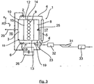
Wie aus den
Wie dies aus den
Auf seinem Weg zum in der
Wie dies insbesondere den
Der Abgaskühler 5 wird bevorzugt als Vollflusskühler betrieben, das heißt, dass das gesamte Kühlmittel durch den Abgaskühler 5 fließt.The
Um sicherzustellen, dass die gegenüber der ersten Abgasrückführleitung 4 wesentlich kürzere Bypassleitung bzw. zweite Abgasrückführleitung 7 das unter Umgehung des Abgaskühlers 5 vom Abgaskrümmer 3 abgezweigte heiße Abgas möglichst ohne Temperaturverlust in den durch den Flanschstutzen 19 ausgebildeten Mischbereich führt, kann die zweite Abgasrückführleitung 7 zusätzlich mit einer thermischen Isolierung versehen sein, was hier allerdings nicht dargestellt ist.To ensure that compared to the first exhaust
Weiter ist am Flanschstutzen 19 stromab der Mündungsbereiche der ersten und zweiten Abgasrückführleitungen 4, 7 ein Luftleitungs-Anschlussflansch 21 ausgebildet, an dem eine Luftleitung 22 angeflanscht ist. Weiter ist am Flanschstutzen 19, stromab des Luftleitungs-Anschlussflansches 21 sowie stromab der Mündungsbereiche der ersten und zweiten Abgasrückführleitungen 4, 7 und damit im Wesentlichen im Bereich einer Luft-Zumischstelle 23 des Flanschstutzens 19 ein Verteilerrohr-Anschlussflansch 24 vorgesehen, an dem ein Luftverteilerrohr 8 der Brennkraftmaschine 9 angeflanscht ist.Next, an air
An dieser Stelle sei erwähnt, dass vorstehend und nachstehend die Begrifflichkeit Flanschverbindung in einem weiten Umfang zu verstehen ist und ausdrücklich auch andere geeignete bzw. äquivalente Anbindungsmöglichkeiten umfassen soll.It should be noted that the term flange connection is to be understood in a broad scope above and below and expressly includes other suitable or equivalent connection possibilities.
Das Luftverteilerrohr 8 ist bevorzugt mit einem stirnseitigen Flanschbereich am Verteilerrohr-Anschlussflansch 24 angeflanscht und erstreckt sich von dort ausgehend im Wesentlichen über die gesamte Länge der Brennkraftmaschine 9 bzw. des Motorblocks 15. Wie dies insbesondere aus den
Wie dies weiter insbesondere der Prinzipdarstellung der
Die Durchflussmenge durch die beiden Absperrventile 2, 6 wird bevorzugt über deren Öffnungsgrad gesteuert. Hierfür weisen die beiden Absperrventile 2, 6 zum Beispiel Wegaufnehmer, über die die Steuer- und/oder Regeleinrichtung 18 den Öffnungsgrad der Absperrventile 2, 6 erfasst, und Aktuatoren 27, 28 (vergleiche
Wie insbesondere die
In den Darstellungen der
Weiter ist, was insbesondere der
Claims (11)
- Exhaust-gas recirculation device (1) for an internal combustion engine of a vehicle,
having a first exhaust-gas recirculation line (4) which can be shut off by means of a first shut-off device (2) and which branches off from an exhaust-gas side (16) of the internal combustion engine (9) and which leads back to an air side (17) of the internal combustion engine (9) via an exhaust-gas cooler (5),
having as second exhaust-gas recirculation line (7) a bypass line which can be shut off by means of a second shut-off device (6) and which bypasses the exhaust-gas cooler (5) and by means of which exhaust gas from the internal combustion engine (9) can be recirculated to the air side (17) of the internal combustion engine (9) without being cooled, wherein the first exhaust-gas recirculation line (4) and the second exhaust-gas recirculation line (7), which forms a bypass line, merge upstream of an air admixing point (23) at which the air conducted to the air side (17) of the internal combustion engine (9) via an air line (22) can be mixed with the recirculated exhaust gas, and
having a control and/or regulating unit (18) by means of which the recirculated exhaust-gas quantity can be controlled and/or regulated, through the actuation of the first and/or second shut-off device (2, 6), as a function of defined and/or predefined exhaust-gas recirculation parameters,
characterized in that the first exhaust-gas recirculation line (4) and the second exhaust-gas recirculation line (7) are branched off by means of separate lines from the exhaust-gas side (16) of the internal combustion engine (9) and are led from there in each case to the opposite air side (17) of the internal combustion engine (9), wherein the first exhaust-gas recirculation line (4), which is longer than the second exhaust-gas recirculation line (7), is subsequently led onward along the internal combustion engine (9) to the air-side opening region of the second exhaust-gas recirculation line (7), where the first and second exhaust-gas recirculation lines (4, 7) merge at a mixing region, wherein the first and second exhaust-gas recirculation lines (4, 7) are led in each case to the air side (17) of the internal combustion engine (9) in the region of and/or along the opposite face sides (12, 13) of an engine block (15) of the internal combustion engine (9) and the mixing region at which the first and second exhaust-gas recirculation lines (4, 7) merge is formed by a flanged connector (19) which is assigned to an end-side housing region of the exhaust-gas cooler (5) as viewed in the direction of longitudinal extent of the exhaust-gas cooler (5) and into which the first exhaust-gas recirculation line (4), which extends through the exhaust-gas cooler (5), opens and to which the second exhaust-gas recirculation line (7) is connected. - Exhaust-gas recirculation device according to Claim 1, characterized in that the first exhaust-gas recirculation line (4) and the second exhaust-gas recirculation line (7) are branched off by means of separate lines from an exhaust manifold (3).
- Exhaust-gas recirculation device according to Claim 2, characterized in that the first exhaust-gas recirculation line (4) is branched off from a first exhaust manifold end region (10) as viewed in the longitudinal direction of an exhaust manifold (3) of the internal combustion engine (9) and in that the second exhaust-gas recirculation line (7) is branched off from a second exhaust manifold end region (11) as viewed in the longitudinal direction of an exhaust manifold (3) of the internal combustion engine (9), which is situated opposite the first exhaust manifold end region (10).
- Exhaust-gas recirculation device according to one of the preceding claims, characterized in that the exhaust-gas cooler (5) extends substantially over the entire length of the internal combustion engine (9).
- Exhaust-gas recirculation device according to one of the preceding claims, characterized in that the flanged connector (19), to which the second exhaust-gas recirculation line (7) is connected, is connected by means of a flange connection (20).
- Exhaust-gas recirculation device according to one of the preceding claims, characterized in that the first exhaust-gas recirculation line (4) merges in a materially integral and/or unipartite fashion into the flanged connector (19), or in that the flanged connector (19) is a separate component which is connected, in particular in a positively locking and/or non-positively locking and/or cohesive manner, to the first exhaust-gas recirculation line (4) and/or to the exhaust-gas cooler (5).
- Exhaust-gas recirculation device according to one of the preceding claims, characterized in that
an air line connection flange (21) is formed on the flanged connector (19) downstream of the opening regions of the first and second exhaust-gas recirculation lines (4, 7), on which air line connection flange the air line (22) is flange-mounted, and
in that furthermore a distributor pipe connection flange (24) is provided on the flanged connector (19) upstream of the air line connection flange (21) and downstream of the opening regions of the first and second exhaust-gas recirculation lines (4, 7) and thus substantially in the region of the air admixing point (23), on which distributor pipe connection flange an air distributor pipe (8) of the internal combustion engine (9) is flange-mounted. - Exhaust-gas recirculation device according to Claim 7, characterized in that the air distributor pipe (8) is flange-mounted with an end-side flange region on the distributor pipe connection flange (24) and extends from there over substantially the entire length of the internal combustion engine (9).
- Exhaust-gas recirculation device according to one of the preceding claims, characterized in that the exhaust-gas cooler (5) runs substantially parallel to the air distributor pipe (8) and/or in that the exhaust-gas cooler (5) is connected, in particular in a materially integral and/or unipartite fashion and/or in a positively locking and/or non-positively locking and/or cohesive fashion, to the air distributor pipe (8).
- Exhaust-gas recirculation device according to one of the preceding claims, characterized in that
at least one temperature sensor (25) is arranged on the air distributor pipe (8), which temperature sensor is coupled in signal-transmitting fashion to the control and/or regulating unit (18) and detects the actual temperature in the air distributor pipe (8),
in that the control and/or regulating unit (18) compares the actual temperature detected by means of the at least one temperature sensor (25) with a defined and/or predefined setpoint temperature, in particular with a load-dependent and/or load-alteration-dependent setpoint temperature stored in a characteristic map (26) of the control and/or regulating unit (18), and if a deviation between the actual temperature and the setpoint temperature is detected, said control and/or regulating unit actuates the first and/or second shut-off device (2, 62) such that an exhaust-gas quantity which sets the setpoint temperature in the air distributor pipe (8) can be recirculated via the first and/or second exhaust-gas recirculation lines (4, 7). - Exhaust-gas recirculation device according to one of the preceding claims, characterized in that a compressor (31), in particular a compressor of an exhaust-gas turbocharger, and/or a charge-air cooler (32) and/or an air filter (33) are/is arranged in the air line (22) upstream of the air admixing point (23).
Applications Claiming Priority (1)
| Application Number | Priority Date | Filing Date | Title |
|---|---|---|---|
| DE102011109264A DE102011109264A1 (en) | 2011-08-03 | 2011-08-03 | Exhaust gas recirculation device for an internal combustion engine of a vehicle and method for operating an exhaust gas recirculation device |
Publications (3)
| Publication Number | Publication Date |
|---|---|
| EP2562407A2 EP2562407A2 (en) | 2013-02-27 |
| EP2562407A3 EP2562407A3 (en) | 2013-06-19 |
| EP2562407B1 true EP2562407B1 (en) | 2016-04-06 |
Family
ID=46581700
Family Applications (1)
| Application Number | Title | Priority Date | Filing Date |
|---|---|---|---|
| EP12005199.0A Active EP2562407B1 (en) | 2011-08-03 | 2012-07-14 | Exhaust gas recirculation device for a combustion engine of a vehicle and method for operating an exhaust gas recirculation device |
Country Status (5)
| Country | Link |
|---|---|
| EP (1) | EP2562407B1 (en) |
| CN (1) | CN102913344B (en) |
| BR (1) | BR102012019403B1 (en) |
| DE (1) | DE102011109264A1 (en) |
| RU (1) | RU2602021C2 (en) |
Families Citing this family (2)
| Publication number | Priority date | Publication date | Assignee | Title |
|---|---|---|---|---|
| JP6255318B2 (en) * | 2014-08-01 | 2017-12-27 | 本田技研工業株式会社 | Uniflow 2-stroke engine |
| DE102016113555B4 (en) * | 2016-07-22 | 2020-03-12 | Pierburg Gmbh | Exhaust system for an internal combustion engine |
Family Cites Families (11)
| Publication number | Priority date | Publication date | Assignee | Title |
|---|---|---|---|---|
| US5617726A (en) | 1995-03-31 | 1997-04-08 | Cummins Engine Company, Inc. | Cooled exhaust gas recirculation system with load and ambient bypasses |
| DE19622891C2 (en) * | 1996-06-07 | 1998-04-09 | Ranco Inc | Exhaust gas recirculation system |
| SE521713C2 (en) * | 1998-11-09 | 2003-12-02 | Stt Emtec Ab | Procedure and apparatus for an EGR system, and such valve |
| DE10011954A1 (en) * | 2000-03-11 | 2001-09-13 | Modine Mfg Co | Exhaust gas heat exchanger in an exhaust gas recirculation arrangement |
| GB0018406D0 (en) * | 2000-07-28 | 2000-09-13 | Serck Heat Transfer Limited | EGR bypass tube cooler |
| US6367256B1 (en) * | 2001-03-26 | 2002-04-09 | Detroit Diesel Corporation | Exhaust gas recirculation with condensation control |
| JP2006037773A (en) * | 2004-07-23 | 2006-02-09 | Denso Corp | Exhaust gas recirculation control device |
| FR2902151B1 (en) * | 2006-06-07 | 2008-08-08 | Peugeot Citroen Automobiles Sa | INTERNAL COMBUSTION ENGINE HAVING AN EXHAUST GAS RECIRCULATION CIRCUIT |
| US7740010B2 (en) * | 2006-10-18 | 2010-06-22 | Eden Innovations Ltd. | System and method of stoichiometric combustion for hydrogen fueled internal combustion engines |
| EP2278148A1 (en) * | 2009-06-23 | 2011-01-26 | Ford Global Technologies, LLC | Internal combustion engine with exhaust gas recirculation and method to operate such an internal combustion engine |
| US8230843B2 (en) * | 2009-07-30 | 2012-07-31 | Ford Global Technologies, Llc | Cooler bypass to reduce condensate in a low-pressure EGR system |
-
2011
- 2011-08-03 DE DE102011109264A patent/DE102011109264A1/en not_active Withdrawn
-
2012
- 2012-07-14 EP EP12005199.0A patent/EP2562407B1/en active Active
- 2012-08-02 RU RU2012133243/06A patent/RU2602021C2/en active
- 2012-08-02 BR BR102012019403-1A patent/BR102012019403B1/en active IP Right Grant
- 2012-08-03 CN CN201210274897.8A patent/CN102913344B/en active Active
Also Published As
| Publication number | Publication date |
|---|---|
| BR102012019403A2 (en) | 2013-11-26 |
| EP2562407A2 (en) | 2013-02-27 |
| CN102913344A (en) | 2013-02-06 |
| BR102012019403B1 (en) | 2021-02-09 |
| CN102913344B (en) | 2016-12-21 |
| RU2602021C2 (en) | 2016-11-10 |
| DE102011109264A1 (en) | 2013-02-07 |
| RU2012133243A (en) | 2014-02-10 |
| EP2562407A3 (en) | 2013-06-19 |
Similar Documents
| Publication | Publication Date | Title |
|---|---|---|
| EP2161438B1 (en) | System and method for recirculating exhaust gas from a combustion engine | |
| DE102009015656B4 (en) | Modular EGR system, engine system, and method for cooling an EGR gas flow | |
| EP1496221A2 (en) | Apparatus for supplying a gas mixture to the intake runners of an internal combustion engine | |
| DE102007049336B4 (en) | Multifunctional module for mounting on an internal combustion engine and for guiding fluids | |
| EP2161429B1 (en) | Suction module for a combustion engine | |
| DE102008048912B4 (en) | Exhaust system and exhaust valve for controlling a volume flow of exhaust gas and a method for controlling a volume flow | |
| EP2305991B1 (en) | Combustion engine with an exhaust gas turbocharger and an exhaust gas return system | |
| EP3027881B1 (en) | Induction module for an internal combustion engine | |
| DE102017118455A1 (en) | Exhaust after-treatment system for an internal combustion engine and method for exhaust aftertreatment of an internal combustion engine | |
| DE102013206690A1 (en) | Internal combustion engine with intercooler and exhaust gas recirculation and method for producing such an internal combustion engine | |
| WO2007009139A1 (en) | Exhaust gas line of an internal combustion engine | |
| EP2562407B1 (en) | Exhaust gas recirculation device for a combustion engine of a vehicle and method for operating an exhaust gas recirculation device | |
| DE102011013496A1 (en) | Internal combustion engine for motor vehicle, has exhaust gas recirculation device with recirculation line, through which exhaust gas is recirculated from exhaust gas tract to intake tract | |
| DE102008047079A1 (en) | Intake module for internal combustion engine, has entrance area, and plenum area for connecting to internal combustion engine, where cooling unit has two cooling sections | |
| DE102007019089A1 (en) | Exhaust gas heat exchanger, exhaust gas heat exchanger system, internal combustion engine and method for treating exhaust gases of an internal combustion engine | |
| AT523180B1 (en) | COMBUSTION MACHINE WITH MULTIPLE CYLINDERS | |
| DE102004013206B4 (en) | Variable cooling device for recirculated exhaust gas to the suction side of a supercharged internal combustion engine | |
| EP2737195B1 (en) | Supercharged internal combustion engine | |
| EP3301290B1 (en) | Channel system for a combustion engine | |
| WO2007028464A1 (en) | Device for controlling an exhaust gas stream | |
| DE102004025185B4 (en) | Air intake duct system for internal combustion engines | |
| DE102018208983A1 (en) | Arrangement for recirculating exhaust gas | |
| DE102010036298B4 (en) | Internal combustion engine with an exhaust pipe having an impact sleeve | |
| DE102006017149A1 (en) | Internal combustion engine`s exhaust gas recirculation system, has one throttle body of exhaust gas recirculating line arranged in compressor housing, and exhaust-gas purification system, which is arranged in exhaust gas line | |
| DE102016200361B4 (en) | Reduction of condensate in an exhaust gas recirculation system |
Legal Events
| Date | Code | Title | Description |
|---|---|---|---|
| PUAI | Public reference made under article 153(3) epc to a published international application that has entered the european phase |
Free format text: ORIGINAL CODE: 0009012 |
|
| AK | Designated contracting states |
Kind code of ref document: A2 Designated state(s): AL AT BE BG CH CY CZ DE DK EE ES FI FR GB GR HR HU IE IS IT LI LT LU LV MC MK MT NL NO PL PT RO RS SE SI SK SM TR |
|
| AX | Request for extension of the european patent |
Extension state: BA ME |
|
| PUAL | Search report despatched |
Free format text: ORIGINAL CODE: 0009013 |
|
| AK | Designated contracting states |
Kind code of ref document: A3 Designated state(s): AL AT BE BG CH CY CZ DE DK EE ES FI FR GB GR HR HU IE IS IT LI LT LU LV MC MK MT NL NO PL PT RO RS SE SI SK SM TR |
|
| AX | Request for extension of the european patent |
Extension state: BA ME |
|
| RIC1 | Information provided on ipc code assigned before grant |
Ipc: F02M 25/07 20060101AFI20130510BHEP Ipc: F02D 41/00 20060101ALI20130510BHEP |
|
| 17P | Request for examination filed |
Effective date: 20140215 |
|
| 17Q | First examination report despatched |
Effective date: 20141104 |
|
| GRAP | Despatch of communication of intention to grant a patent |
Free format text: ORIGINAL CODE: EPIDOSNIGR1 |
|
| INTG | Intention to grant announced |
Effective date: 20151203 |
|
| GRAS | Grant fee paid |
Free format text: ORIGINAL CODE: EPIDOSNIGR3 |
|
| REG | Reference to a national code |
Ref country code: DE Ref legal event code: R079 Ref document number: 502012006542 Country of ref document: DE Free format text: PREVIOUS MAIN CLASS: F02M0025070000 Ipc: F02M0026000000 |
|
| GRAA | (expected) grant |
Free format text: ORIGINAL CODE: 0009210 |
|
| RIC1 | Information provided on ipc code assigned before grant |
Ipc: F02D 41/00 20060101ALI20160210BHEP Ipc: F02M 26/00 20160101AFI20160210BHEP |
|
| AK | Designated contracting states |
Kind code of ref document: B1 Designated state(s): AL AT BE BG CH CY CZ DE DK EE ES FI FR GB GR HR HU IE IS IT LI LT LU LV MC MK MT NL NO PL PT RO RS SE SI SK SM TR |
|
| REG | Reference to a national code |
Ref country code: GB Ref legal event code: FG4D Free format text: NOT ENGLISH |
|
| REG | Reference to a national code |
Ref country code: AT Ref legal event code: REF Ref document number: 788103 Country of ref document: AT Kind code of ref document: T Effective date: 20160415 Ref country code: CH Ref legal event code: EP |
|
| REG | Reference to a national code |
Ref country code: IE Ref legal event code: FG4D Free format text: LANGUAGE OF EP DOCUMENT: GERMAN |
|
| REG | Reference to a national code |
Ref country code: DE Ref legal event code: R096 Ref document number: 502012006542 Country of ref document: DE |
|
| REG | Reference to a national code |
Ref country code: NL Ref legal event code: FP |
|
| REG | Reference to a national code |
Ref country code: SE Ref legal event code: TRGR |
|
| REG | Reference to a national code |
Ref country code: FR Ref legal event code: PLFP Year of fee payment: 5 |
|
| REG | Reference to a national code |
Ref country code: LT Ref legal event code: MG4D |
|
| PG25 | Lapsed in a contracting state [announced via postgrant information from national office to epo] |
Ref country code: PL Free format text: LAPSE BECAUSE OF FAILURE TO SUBMIT A TRANSLATION OF THE DESCRIPTION OR TO PAY THE FEE WITHIN THE PRESCRIBED TIME-LIMIT Effective date: 20160406 Ref country code: FI Free format text: LAPSE BECAUSE OF FAILURE TO SUBMIT A TRANSLATION OF THE DESCRIPTION OR TO PAY THE FEE WITHIN THE PRESCRIBED TIME-LIMIT Effective date: 20160406 Ref country code: IS Free format text: LAPSE BECAUSE OF FAILURE TO SUBMIT A TRANSLATION OF THE DESCRIPTION OR TO PAY THE FEE WITHIN THE PRESCRIBED TIME-LIMIT Effective date: 20160806 Ref country code: NO Free format text: LAPSE BECAUSE OF FAILURE TO SUBMIT A TRANSLATION OF THE DESCRIPTION OR TO PAY THE FEE WITHIN THE PRESCRIBED TIME-LIMIT Effective date: 20160706 Ref country code: LT Free format text: LAPSE BECAUSE OF FAILURE TO SUBMIT A TRANSLATION OF THE DESCRIPTION OR TO PAY THE FEE WITHIN THE PRESCRIBED TIME-LIMIT Effective date: 20160406 |
|
| PG25 | Lapsed in a contracting state [announced via postgrant information from national office to epo] |
Ref country code: RS Free format text: LAPSE BECAUSE OF FAILURE TO SUBMIT A TRANSLATION OF THE DESCRIPTION OR TO PAY THE FEE WITHIN THE PRESCRIBED TIME-LIMIT Effective date: 20160406 Ref country code: PT Free format text: LAPSE BECAUSE OF FAILURE TO SUBMIT A TRANSLATION OF THE DESCRIPTION OR TO PAY THE FEE WITHIN THE PRESCRIBED TIME-LIMIT Effective date: 20160808 Ref country code: GR Free format text: LAPSE BECAUSE OF FAILURE TO SUBMIT A TRANSLATION OF THE DESCRIPTION OR TO PAY THE FEE WITHIN THE PRESCRIBED TIME-LIMIT Effective date: 20160707 Ref country code: HR Free format text: LAPSE BECAUSE OF FAILURE TO SUBMIT A TRANSLATION OF THE DESCRIPTION OR TO PAY THE FEE WITHIN THE PRESCRIBED TIME-LIMIT Effective date: 20160406 Ref country code: LV Free format text: LAPSE BECAUSE OF FAILURE TO SUBMIT A TRANSLATION OF THE DESCRIPTION OR TO PAY THE FEE WITHIN THE PRESCRIBED TIME-LIMIT Effective date: 20160406 Ref country code: ES Free format text: LAPSE BECAUSE OF FAILURE TO SUBMIT A TRANSLATION OF THE DESCRIPTION OR TO PAY THE FEE WITHIN THE PRESCRIBED TIME-LIMIT Effective date: 20160406 |
|
| PG25 | Lapsed in a contracting state [announced via postgrant information from national office to epo] |
Ref country code: BE Free format text: LAPSE BECAUSE OF NON-PAYMENT OF DUE FEES Effective date: 20160731 |
|
| REG | Reference to a national code |
Ref country code: DE Ref legal event code: R097 Ref document number: 502012006542 Country of ref document: DE |
|
| PG25 | Lapsed in a contracting state [announced via postgrant information from national office to epo] |
Ref country code: CZ Free format text: LAPSE BECAUSE OF FAILURE TO SUBMIT A TRANSLATION OF THE DESCRIPTION OR TO PAY THE FEE WITHIN THE PRESCRIBED TIME-LIMIT Effective date: 20160406 Ref country code: RO Free format text: LAPSE BECAUSE OF FAILURE TO SUBMIT A TRANSLATION OF THE DESCRIPTION OR TO PAY THE FEE WITHIN THE PRESCRIBED TIME-LIMIT Effective date: 20160406 Ref country code: SK Free format text: LAPSE BECAUSE OF FAILURE TO SUBMIT A TRANSLATION OF THE DESCRIPTION OR TO PAY THE FEE WITHIN THE PRESCRIBED TIME-LIMIT Effective date: 20160406 Ref country code: EE Free format text: LAPSE BECAUSE OF FAILURE TO SUBMIT A TRANSLATION OF THE DESCRIPTION OR TO PAY THE FEE WITHIN THE PRESCRIBED TIME-LIMIT Effective date: 20160406 Ref country code: DK Free format text: LAPSE BECAUSE OF FAILURE TO SUBMIT A TRANSLATION OF THE DESCRIPTION OR TO PAY THE FEE WITHIN THE PRESCRIBED TIME-LIMIT Effective date: 20160406 |
|
| PLBE | No opposition filed within time limit |
Free format text: ORIGINAL CODE: 0009261 |
|
| STAA | Information on the status of an ep patent application or granted ep patent |
Free format text: STATUS: NO OPPOSITION FILED WITHIN TIME LIMIT |
|
| PG25 | Lapsed in a contracting state [announced via postgrant information from national office to epo] |
Ref country code: SM Free format text: LAPSE BECAUSE OF FAILURE TO SUBMIT A TRANSLATION OF THE DESCRIPTION OR TO PAY THE FEE WITHIN THE PRESCRIBED TIME-LIMIT Effective date: 20160406 |
|
| REG | Reference to a national code |
Ref country code: CH Ref legal event code: PL |
|
| 26N | No opposition filed |
Effective date: 20170110 |
|
| GBPC | Gb: european patent ceased through non-payment of renewal fee |
Effective date: 20160714 |
|
| PG25 | Lapsed in a contracting state [announced via postgrant information from national office to epo] |
Ref country code: MC Free format text: LAPSE BECAUSE OF FAILURE TO SUBMIT A TRANSLATION OF THE DESCRIPTION OR TO PAY THE FEE WITHIN THE PRESCRIBED TIME-LIMIT Effective date: 20160406 |
|
| PG25 | Lapsed in a contracting state [announced via postgrant information from national office to epo] |
Ref country code: CH Free format text: LAPSE BECAUSE OF NON-PAYMENT OF DUE FEES Effective date: 20160731 Ref country code: LI Free format text: LAPSE BECAUSE OF NON-PAYMENT OF DUE FEES Effective date: 20160731 |
|
| REG | Reference to a national code |
Ref country code: IE Ref legal event code: MM4A |
|
| PG25 | Lapsed in a contracting state [announced via postgrant information from national office to epo] |
Ref country code: GB Free format text: LAPSE BECAUSE OF NON-PAYMENT OF DUE FEES Effective date: 20160714 Ref country code: SI Free format text: LAPSE BECAUSE OF FAILURE TO SUBMIT A TRANSLATION OF THE DESCRIPTION OR TO PAY THE FEE WITHIN THE PRESCRIBED TIME-LIMIT Effective date: 20160406 |
|
| REG | Reference to a national code |
Ref country code: FR Ref legal event code: PLFP Year of fee payment: 6 |
|
| PG25 | Lapsed in a contracting state [announced via postgrant information from national office to epo] |
Ref country code: IE Free format text: LAPSE BECAUSE OF NON-PAYMENT OF DUE FEES Effective date: 20160714 |
|
| PG25 | Lapsed in a contracting state [announced via postgrant information from national office to epo] |
Ref country code: LU Free format text: LAPSE BECAUSE OF NON-PAYMENT OF DUE FEES Effective date: 20160714 |
|
| PG25 | Lapsed in a contracting state [announced via postgrant information from national office to epo] |
Ref country code: HU Free format text: LAPSE BECAUSE OF FAILURE TO SUBMIT A TRANSLATION OF THE DESCRIPTION OR TO PAY THE FEE WITHIN THE PRESCRIBED TIME-LIMIT; INVALID AB INITIO Effective date: 20120714 Ref country code: CY Free format text: LAPSE BECAUSE OF FAILURE TO SUBMIT A TRANSLATION OF THE DESCRIPTION OR TO PAY THE FEE WITHIN THE PRESCRIBED TIME-LIMIT Effective date: 20160406 |
|
| PG25 | Lapsed in a contracting state [announced via postgrant information from national office to epo] |
Ref country code: TR Free format text: LAPSE BECAUSE OF FAILURE TO SUBMIT A TRANSLATION OF THE DESCRIPTION OR TO PAY THE FEE WITHIN THE PRESCRIBED TIME-LIMIT Effective date: 20160406 Ref country code: MT Free format text: LAPSE BECAUSE OF FAILURE TO SUBMIT A TRANSLATION OF THE DESCRIPTION OR TO PAY THE FEE WITHIN THE PRESCRIBED TIME-LIMIT Effective date: 20160406 Ref country code: MK Free format text: LAPSE BECAUSE OF FAILURE TO SUBMIT A TRANSLATION OF THE DESCRIPTION OR TO PAY THE FEE WITHIN THE PRESCRIBED TIME-LIMIT Effective date: 20160406 |
|
| REG | Reference to a national code |
Ref country code: FR Ref legal event code: PLFP Year of fee payment: 7 |
|
| PG25 | Lapsed in a contracting state [announced via postgrant information from national office to epo] |
Ref country code: BG Free format text: LAPSE BECAUSE OF FAILURE TO SUBMIT A TRANSLATION OF THE DESCRIPTION OR TO PAY THE FEE WITHIN THE PRESCRIBED TIME-LIMIT Effective date: 20160406 |
|
| REG | Reference to a national code |
Ref country code: AT Ref legal event code: MM01 Ref document number: 788103 Country of ref document: AT Kind code of ref document: T Effective date: 20170714 |
|
| PG25 | Lapsed in a contracting state [announced via postgrant information from national office to epo] |
Ref country code: AL Free format text: LAPSE BECAUSE OF FAILURE TO SUBMIT A TRANSLATION OF THE DESCRIPTION OR TO PAY THE FEE WITHIN THE PRESCRIBED TIME-LIMIT Effective date: 20160406 |
|
| PG25 | Lapsed in a contracting state [announced via postgrant information from national office to epo] |
Ref country code: AT Free format text: LAPSE BECAUSE OF NON-PAYMENT OF DUE FEES Effective date: 20170714 |
|
| REG | Reference to a national code |
Ref country code: DE Ref legal event code: R081 Ref document number: 502012006542 Country of ref document: DE Owner name: MAN TRUCK & BUS SE, DE Free format text: FORMER OWNER: MAN TRUCK & BUS AG, 80995 MUENCHEN, DE |
|
| PGFP | Annual fee paid to national office [announced via postgrant information from national office to epo] |
Ref country code: SE Payment date: 20230317 Year of fee payment: 12 |
|
| PGFP | Annual fee paid to national office [announced via postgrant information from national office to epo] |
Ref country code: NL Payment date: 20230726 Year of fee payment: 12 |
|
| PGFP | Annual fee paid to national office [announced via postgrant information from national office to epo] |
Ref country code: IT Payment date: 20230721 Year of fee payment: 12 |
|
| PGFP | Annual fee paid to national office [announced via postgrant information from national office to epo] |
Ref country code: FR Payment date: 20230725 Year of fee payment: 12 Ref country code: DE Payment date: 20230726 Year of fee payment: 12 |