EP2562015B1 - Unité de soupape d'essieu relevable - Google Patents
Unité de soupape d'essieu relevable Download PDFInfo
- Publication number
- EP2562015B1 EP2562015B1 EP12180543.6A EP12180543A EP2562015B1 EP 2562015 B1 EP2562015 B1 EP 2562015B1 EP 12180543 A EP12180543 A EP 12180543A EP 2562015 B1 EP2562015 B1 EP 2562015B1
- Authority
- EP
- European Patent Office
- Prior art keywords
- lift axle
- valve unit
- axle valve
- heating element
- heating
- Prior art date
- Legal status (The legal status is an assumption and is not a legal conclusion. Google has not performed a legal analysis and makes no representation as to the accuracy of the status listed.)
- Not-in-force
Links
- 238000010438 heat treatment Methods 0.000 claims description 119
- 230000004913 activation Effects 0.000 claims description 17
- 238000013016 damping Methods 0.000 claims description 17
- 239000000725 suspension Substances 0.000 claims description 12
- 230000009849 deactivation Effects 0.000 claims description 8
- 238000012546 transfer Methods 0.000 description 13
- 230000006870 function Effects 0.000 description 11
- 230000001419 dependent effect Effects 0.000 description 7
- 238000013461 design Methods 0.000 description 7
- 230000008901 benefit Effects 0.000 description 3
- 230000008859 change Effects 0.000 description 3
- 238000004891 communication Methods 0.000 description 3
- 230000000694 effects Effects 0.000 description 3
- 230000010354 integration Effects 0.000 description 3
- 238000009423 ventilation Methods 0.000 description 3
- 230000005540 biological transmission Effects 0.000 description 2
- 230000008878 coupling Effects 0.000 description 2
- 238000010168 coupling process Methods 0.000 description 2
- 238000005859 coupling reaction Methods 0.000 description 2
- 238000009826 distribution Methods 0.000 description 2
- 238000004519 manufacturing process Methods 0.000 description 2
- 238000000034 method Methods 0.000 description 2
- 238000005192 partition Methods 0.000 description 2
- 238000003860 storage Methods 0.000 description 2
- 238000013022 venting Methods 0.000 description 2
- XSQUKJJJFZCRTK-UHFFFAOYSA-N Urea Chemical compound NC(N)=O XSQUKJJJFZCRTK-UHFFFAOYSA-N 0.000 description 1
- 239000006096 absorbing agent Substances 0.000 description 1
- 230000003213 activating effect Effects 0.000 description 1
- 238000004378 air conditioning Methods 0.000 description 1
- 239000004202 carbamide Substances 0.000 description 1
- 238000002485 combustion reaction Methods 0.000 description 1
- 230000006835 compression Effects 0.000 description 1
- 238000007906 compression Methods 0.000 description 1
- 238000001816 cooling Methods 0.000 description 1
- 230000003111 delayed effect Effects 0.000 description 1
- 238000011161 development Methods 0.000 description 1
- 230000018109 developmental process Effects 0.000 description 1
- 230000007613 environmental effect Effects 0.000 description 1
- 239000012530 fluid Substances 0.000 description 1
- 239000000446 fuel Substances 0.000 description 1
- 238000009434 installation Methods 0.000 description 1
- 238000009413 insulation Methods 0.000 description 1
- 239000000463 material Substances 0.000 description 1
- 230000007246 mechanism Effects 0.000 description 1
- 238000012986 modification Methods 0.000 description 1
- 230000004048 modification Effects 0.000 description 1
- 230000003287 optical effect Effects 0.000 description 1
- 238000013021 overheating Methods 0.000 description 1
- 235000011837 pasties Nutrition 0.000 description 1
- 230000008569 process Effects 0.000 description 1
- 238000012545 processing Methods 0.000 description 1
- 230000009467 reduction Effects 0.000 description 1
- 230000001105 regulatory effect Effects 0.000 description 1
- 230000004044 response Effects 0.000 description 1
- 238000007789 sealing Methods 0.000 description 1
- 230000035939 shock Effects 0.000 description 1
- 230000001502 supplementing effect Effects 0.000 description 1
- 238000012360 testing method Methods 0.000 description 1
- 238000012549 training Methods 0.000 description 1
- 230000000007 visual effect Effects 0.000 description 1
Images


Classifications
-
- B—PERFORMING OPERATIONS; TRANSPORTING
- B60—VEHICLES IN GENERAL
- B60G—VEHICLE SUSPENSION ARRANGEMENTS
- B60G17/00—Resilient suspensions having means for adjusting the spring or vibration-damper characteristics, for regulating the distance between a supporting surface and a sprung part of vehicle or for locking suspension during use to meet varying vehicular or surface conditions, e.g. due to speed or load
- B60G17/02—Spring characteristics, e.g. mechanical springs and mechanical adjusting means
- B60G17/04—Spring characteristics, e.g. mechanical springs and mechanical adjusting means fluid spring characteristics
- B60G17/052—Pneumatic spring characteristics
- B60G17/0523—Regulating distributors or valves for pneumatic springs
- B60G17/0526—Distributor units, e.g. for retractable wheels
-
- B—PERFORMING OPERATIONS; TRANSPORTING
- B60—VEHICLES IN GENERAL
- B60G—VEHICLE SUSPENSION ARRANGEMENTS
- B60G2600/00—Indexing codes relating to particular elements, systems or processes used on suspension systems or suspension control systems
- B60G2600/72—Cooling or warming means
-
- Y—GENERAL TAGGING OF NEW TECHNOLOGICAL DEVELOPMENTS; GENERAL TAGGING OF CROSS-SECTIONAL TECHNOLOGIES SPANNING OVER SEVERAL SECTIONS OF THE IPC; TECHNICAL SUBJECTS COVERED BY FORMER USPC CROSS-REFERENCE ART COLLECTIONS [XRACs] AND DIGESTS
- Y10—TECHNICAL SUBJECTS COVERED BY FORMER USPC
- Y10T—TECHNICAL SUBJECTS COVERED BY FORMER US CLASSIFICATION
- Y10T137/00—Fluid handling
- Y10T137/6416—With heating or cooling of the system
Definitions
- the invention relates to a Liftachsventiliser, which is intended for use in a commercial vehicle with air suspension.
- a commercial vehicle is in particular a semi-trailer, a trailer, a bus or a tractor.
- Lift axle valve units are used to adjust the number of axles of the commercial vehicle that carry an axle load as needed.
- the commercial vehicle is empty or loaded only below a threshold for loading, one or more lift axles can be lifted.
- the threshold value of the loading is exceeded, at least one lift axle is automatically lowered by means of the lift axle valve unit, for which purpose a ventilation of lift bellows takes place, which lifts the lift axle in the ventilated state.
- air suspension bellows of the lift axle are ventilated to support the axle load of the lift axle.
- the aim of changing the number of axles of the commercial vehicle bearing an axle load may be to minimize the wear of the tires associated with the axles and / or to guarantee an improved braking behavior for different loads.
- the lift axle valve unit can be responsible for changing the pneumatic loading of the air spring bellows of the constantly active axles and the activated lift axle in accordance with a desired distribution of the axle loads on the effective axles in the case of lowering the lift axle.
- An additional use of the lift axle must also be made in order to prevent the required maximum braking force to be brought about by means of the brake system with increasing load and thus increasing normal force between tire and roadway.
- DE 199 05 113 B4 also discloses the possibility of briefly lifting a lift axle to be lowered in view of the load in order to specifically overload a drive axle of the utility vehicle in order to support a start-up procedure on a smooth or poorly meshed ground.
- Lift axle valve units which at least partially ensure the aforementioned functions are known from the prior art. Only by way of example with regard to the basic and structural design of such Liftachsventiliseren to the documents US 2011/0101257 A1 . EP 0 170 794 A2 . DE 199 05 113 B4 . DE 44 10 892 C2 . DE 43 14 994 C1 . DE 40 37 461 C1 . DE 36 38 849 A1 and DE 89 11 010 U1 directed. Lift axle valve units may be controlled or regulated manually, automatically, mechanically, pneumatically and / or electronically.
- DE 10 2004 051 812 A1 discloses a compressed air supply device with an air treatment module with an air dryer and circuit protection devices for several consumer circuits and an electronic control unit.
- a heater is arranged adjacent to the control unit, obviously to ensure a minimum temperature of the control unit and / or a minimum temperature of the air dryer and the pressure regulator.
- the compressed air supply device is formed integrally with a designated as Liftachsmodul valve group.
- the non-generic document US 3,401,948 A relates to a level control system of an automobile in which the vehicle wheels are supported via air spring bellows with parallel metallic springs and shock absorbers.
- the air bellows are supplied with compressed air by a pump via a valve unit.
- the valve unit has a check valve, via which the compressed air in the air spring bellows can be secured without pump delivery.
- the valve unit has a venting valve, by means of which, when the loading of the automobile is reduced, an increase in the level can be counteracted by means of venting of the air-suspension bellows.
- the electric Operation of the valve unit via an electrical level switch, which is coupled via a mechanical linkage with a differential gear of the automobile.
- the vent valve is opened and closed via a coil. At low temperatures, the breather valve coil can serve to melt frozen condensate from the compressed air.
- DE 195 15 895 A1 discloses a heating device in series with a thermal switch, by means of which a safety valve on the wet side of the dryer in a motor vehicle compressed air supply device can be heated as needed.
- the invention has for its object to propose a Liftachsventil, which is improved in terms of its function and / or reliability.
- the invention is based on the observation that in the operation of commercial vehicles with lift axles at low ambient temperatures can affect the Liftachsfunktion, which may also be the case when the ambient temperatures during the operation of the commercial vehicle on the day itself are not so low, but low temperatures prevailed during the night.
- the ambient temperature may be less than -40.degree. C., resulting in cooling of the lift axle valve unit, which is also partly maintained due to the insulation and heat capacity of the lift axle valve unit when the ambient temperature increases during the day.
- a reduced temperature of the lift axle valve unit can lead to excessive leakage in the lift axle valve unit, in particular as a result of changed fitting choices and incorrectly closing valve seats.
- the Liftachsventiliser has a heater by means of which (alternatively or cumulatively) to the aforementioned mechanisms for heating the Liftachsventiliser heating of the Liftachsventiliser can be brought about as needed.
- the heating device can be designed as a compact heating device or as a distributed device with a plurality of components of any desired configuration, which can be distributed over the lift axle valve unit to suitable locations.
- the heating device or said components may be at least partially integrated into a housing of the lift axle valve unit or any components or attached to a housing of the lift axle valve unit.
- the lift axle valve unit according to the invention is designed in particular as a singular component and is formed and arranged separately and at a distance from the compressed air conditioning device, in particular in the region of the associated lift axle.
- the heating device is designed as a module, which can thus be combined "as a whole" with a basic module of the Liftachsventiliser, in particular the housing thereof, for example, can be attached thereto from the outside or can be integrated into this.
- the module can be prefabricated by the manufacturer, the basic module of the lifting axle valve unit or by another manufacturer.
- the Liftachsventiltician is distributed in two variants, namely on the one hand with the module that forms the heater, for countries where low temperatures are expected, and on the other hand without a modular heating device for use of the commercial vehicle with Liftachsventiltechnik in countries or areas or a season in which low temperatures are not expected. It is also possible that one and the same vehicle is retrofitted by supplementing the modular heating device (temporarily or permanently) in order to make it usable for low temperatures.
- a housing of the lifting axle valve unit for example an outer wall or an inner wall arranged in the interior, has a recess.
- the heater has a heating element.
- the heating element is arranged in the recess of the housing, so that a transfer of heat from the heating element to the housing is possible.
- the transfer between the heating element and the housing is improved by an intermediate body between the heating element and the housing such as a thermal contact element or an introduced with mounting and curing fluid or pasty medium, an elastic balancing body or the like is interposed.
- the heating device has a heating element in training as a kind of "heating mat”.
- This heating mat can then with an enlarged contact surface on a Contact surface of the housing, for example, from the outside to an outer wall of the housing or integrated into the interior of the housing on the inside of the outer housing wall or abut an intermediate wall, whereby a good transfer of heat can be ensured.
- the arrangement of a heating element can take place at any point of the Liftachsventiliser, in which case a transfer of heat from the heating element to valve elements of the Liftachsventiliser, housing bores for the valve elements u. ⁇ . Can be done by the compressed air in the Liftachsventiliser and / or by convection of the housing or other pneumatic components of the Liftachsventiliser.
- the invention also includes embodiments in which a heating element is associated with a valve element to be heated immediately adjacent. If several valve elements are to be heated, it is also possible for each valve element to have its own heating element immediately adjacent to it.
- a heating element between at least two valve elements of the lifting axle valve unit is arranged, whereby a heating element can be used multifunctional for heating the at least two valve elements without unnecessarily long transmission paths for the heat of the heating element to the valve elements must be taken into account.
- the heating element can be arranged in a common plane of two valve elements, in particular centrally between two longitudinal or actuation axes thereof. Three or more valve elements to be heated may also be spatially arranged around a common heating element.
- the operation of the heater may be done manually by the driver or an operator, whereby the driver or operator may decide for himself whether actuation of the heater is required, which may be based on a sensed or measured outside temperature or even in the event that the driver observes that the Liftachsventiliser not working properly. It is also possible that the driver is automatically given an information depending on the ambient temperature that the operation of the heater is advisable, for example via an audible or visual warning signal. In these cases, manual operation of the heater would activate an electrical power supply to the heater.
- a temperature sensor at any point of the commercial vehicle, in particular in or on the Liftachsventiliser be arranged.
- the heating device itself has a temperature sensor. This results in a particularly compact embodiment in which a summary of the electrical components of the heater and the temperature sensor is possible. If the heating device has a modular design and is only part of the lift axle valve unit when required, the heating element and the temperature sensor can be provided by this module at the same time, which can reduce a manufacturing, storage and assembly costs.
- the temperature sensor is formed with a temperature switch which activates the or a heating element when an activation threshold value of the temperature of the temperature switch (and thus the immediately adjacent components of the Liftachsventiliser) is exceeded.
- a temperature switch represents a particularly cost-effective, but reliable design of a temperature sensor.
- the temperature switch may be formed with a bimetallic switching element in per se known configuration. It is possible in this case that an output signal dependent on the operating position of the temperature switch is fed to a control unit of the lift axle valve unit or an external control unit or is used to actuate a further switching element of the heating device, which then ultimately activates the heating element.
- the temperature switch of the heater interrupts a continuous electrical power supply of the heater and the heating element, if the temperature is above the activation threshold.
- the activation threshold value is undershot, the electrical charging of the heating element takes place (without any additional additional components required), whereby the heating can be brought about.
- only needs an electrical power supply are provided for the heating device of the lifting axle valve unit according to the invention, so also only a corresponding connection to the Liftachsventiliser or the modular heater are provided without external measures to be taken for activation and deactivation of the Liftachsventiltician.
- the temperature switch deactivates the heating element when a deactivation threshold value of the temperature has been exceeded.
- the deactivation threshold value of the temperature is greater than the activation threshold value of the temperature, so that a kind of hysteresis for the switching positions of the temperature switch is given as a function of the temperature. According to the invention can thus be ensured that falls below the activation threshold, the heating element is activated, whereby a heating of the Liftachsventiliser and thus also the temperature switch takes place. If, with such activated heating, the temperature exceeds the deactivation threshold of the temperature for which the proper operation of the lift axle valve unit is ensured, the heater is automatically deactivated to avoid overheating and / or reduce the electrical power consumption to the required level ,
- a special measure takes into account the fact that it is more critical for the operational safety of the commercial vehicle, the guarantee of braking performance and the wear of the tires if the lift axle is not lowered due to the low temperature, although this would be indicated as a result of the loading of the commercial vehicle that the lift axle is not raised, although this would be required in view of the load. Based on this observation, the invention minimizes the electric power consumption by the heater by using any type of control device which makes the activation of the heater dependent on the condition that the lift axle valve unit is in a shift position in which the lift axle is raised.
- the actuation of the heater may be made dependent on any other operating and environmental conditions.
- the actuation of the heating device is dependent on the fact that the ignition is activated, thereby avoiding that a load of a vehicle battery is performed by the heater, without that as a result of the running internal combustion engine, replenishment of energy to the battery.
- the power supply of the heater is arbitrary, so that it can be done by a separately provided for this purpose battery or accumulator, a built in the heater or the Liftachsventiliki battery or such an integrated accumulator. Also possible is the feeding of the heater of a battery and / or alternator of the commercial vehicle.
- the invention proposes in a further embodiment, (at least) to arrange a heating element in a damping container of the Liftachsventiliser.
- the invention here makes the location of the damping tank as a particularly suitable location with possibly existing installation space.
- the arrangement of the heating element in the damping tank convection of the heating element via the connection to the damper walls bounding the walls and / or heating of the compressed air in the damping tank with the transport of the thus heated compressed air to be heated to the valve elements.
- a multifunctional heating element is obtained if, in addition to its function as described above, it is also used to form a throttle or to limit a throttle cross section when it is integrated into the damping reservoir.
- the heating device may have a control connection for activating and deactivating the same, a connection for an electrical power supply and / or an output connection for an operating signal of the heating device, the signal of a temperature sensor or temperature switch u. ä. own.
- the aforementioned connections can be designed as individual connection plugs or combined connection plugs.
- the at least one connection can be connected to a corresponding connection of the lift axle valve unit, wherein a connection with an input and output connection of the lift axle valve unit can take place via this connection. It is also possible that a connection of the at least one terminal of the heater takes place without further electrical coupling with the Liftachsventiltechnik with other electrical and electronic components of the commercial vehicle. Also possible is a communication of the heater with a CAN in any known configuration.
- a further aspect of the present invention relates to the first-time use of a heating device, by means of which a heating of a lifting axle valve unit of a commercial vehicle with air suspension can be carried out as required and the previously explained advantages can be brought about.
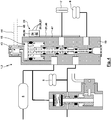
- the present invention can basically be used in the context of Liftachsventiliseren of any design to ensure the basic Liftachsfunktion. For this reason are in the Fig. 1 to 4 Liftachsventiliseren 1 shown in which a basic module 2 or body is designed differently to ensure the Liftachsfunktionen.
- the basic module 2 corresponds to the Liftachsventiliser 1 according Fig. 1 the lift axle valve, as this in detail in DE 43 14 994 C1 the applicant is described.
- basic modules 2 Liftachsventiliser 1 is in particular to the documents DE 43 14 994 C1 .
- DE 44 10 892 C2 and DE 40 37 461 C1 directed are in particular to the documents DE 43 14 994 C1 .
- the basic module 2 is formed with an in Fig. 1 only schematically illustrated housing 19, which is multi-part with partitions u. ⁇ . May be formed and can have any geometry. While in Fig. 1 the said pneumatic elements are arranged in a plane, the skilled person understands that they can be arranged arbitrarily spatially to achieve a compact design. It is also possible that the base module 2 may be formed with a plurality of sub-modules, which are set in one another and / or attached to each other, for example, are flanged to each other, with the Placing or flanging also a production and sealing of required pneumatic line connections can be done.
- Fig. 1 have the control piston 8 and the switching piston 13 via mutually parallel longitudinal and symmetry axes and actuation axes.
- the heating element 21 and the recess 20 extend parallel to the longitudinal and actuating axes of the control piston 8 and the switching piston 13 in the plane defined by the longitudinal and symmetry axes and actuating axes of the control piston 8 and the switching piston 13 plane.
- the recess 20 and the heating element 21 are preferably arranged approximately centrally between these longitudinal and actuating axes.
- Fig. 2 shows an embodiment of the invention, in which the basic module 2 of the lifting axle valve unit 1 deviating from Fig. 1 is formed without Achsliftventil 12. Rather, here controls the control valve 10 without the interposition of a Achsliftventils 12 directly to a single switching valve 15. In addition, it can be seen here that the air spring bellows are acted upon by a mechanical level control valve 28. Manual actuation of the axle lift valve 12 can ensure the traction aid described in the introduction in winter. For the embodiment according to Fig. 2 is the manual operation to ensure a traction help directly by an operating knob on the switching valve 15 allows.
- the Liftachsventiltician 1 has a damping container 29 which is pneumatically connected to the air spring bellows 5 'and the output of the level control valve 28 and the control piston 8 via a throttle 33 applied to the front side.
- the damping tank 29 serves to decouple the pneumatic actuation of the control piston 8 from short-term dynamic fluctuations of the pressure in the air spring bellows 5 '.
- the heating element 21 is integrated in the damping tank 29.
- the main body 24 is attached to the housing 19.
- the heating element 21 extends through a through bore 30 of a wall of the housing 19 in an interior space 31, where the heating element 21 occurs in the region of its lateral surface in operative connection with the compressed air and can heat them.
- the heated compressed air can then reach the other components of the Liftachsventiliser 1 via the illustrated pneumatic line connection.
- the heating element 21 extends through an intermediate wall 32 of the damping container 29.
- the throttle 33 is formed.
- the throttle 33 separates chambers 34, 35 of the damping tank 29 and throttles the
- the intermediate wall 32 of the damping tank 29 is formed by a heat transfer body 36, which is part of the heater 23, supported or fixed to an inner wall of the damping tank 29 and in particular of the housing 19 and forms the throttle 33 or a throttle cross-section of the throttle 33rd with limited.
- the heat transfer body 36 also ensures a transfer of heat from the heating element 21 via the contact with the inner wall of the damping tank 29 to the housing 19 and thus to other pneumatic components, in particular the control valve 10th
- Fig. 3 basically shows one Fig. 1 corresponding embodiment of the Liftachsventiliser 1.
- the control valve 10 is formed with an additional pneumatically controlled load piston 37.
- the terminals 25, 26, 27 form an interface 38 for a control unit 39, in particular an ECU. This controls the electrical power supply of the heater, the activation and deactivation of the same and can process outputs of the heater 23.
- the control unit 39 communicates via at least one connector with the interface 38 and thus the heater 23.
- the control unit 39 receives a signal of a speed sensor 40, in particular an ABS / EBS sensor in conjunction with a corresponding pole.
- the control unit 39 has a speed signal of a vehicle wheel. If a sensor, for example a temperature sensor integrated in the heating device 21 or a temperature switch, detects the control unit 39 too low a temperature for safe operation of the lifting axle valve unit 1 and the speed sensor 40 signals the recording of a driving operation, the control unit 39 can transmit by means of a suitable optical or acoustic signal Display, in particular a warning light 41, bring the driver note that the operation of the Liftachsventiliser 1 may not be possible.
- a pneumatic pressure and / or a position of a valve element of the Liftachsventiliser 1 can be supplied, from which the control unit 39 directly to a faulty function of the lift axle valve unit 1 can close and can initiate appropriate measures such as the activation of the heater 23 and / or the warning of the driver.
- other communication options such as communication via the CAN or PLC can be used to exchange the aforementioned data, in particular to inform the driver.
- the damping container 29 has an outlet port 42, via which it can be connected to other valves, for example with a stopcock or a test port.
- Fig. 4 shows a different embodiment of a Liftachsventiliser 1, in which a change-over valve 15 is electrically operated.
- the Liftachsventiliser 1 has an electrically operated solenoid valve 43, which is controlled by control lines 44, 45 from a control unit, not shown.
- the solenoid valve 43 aerates and vents a control chamber for switching the changeover valve 15 depending on the control signal in the control lines 44, 45.
- the heater 23 is formed with a heating element 21 in the form of a heating mat 46, which as possible to ensure the required heat transfer surfaces as large as possible abuts a contact surface 47 which is formed from the outside of the housing 19.
- the application of the heating mat 46 can be simplified if the contact surface 47 of the housing 19 is planar or simply curved.
- the heating device 23 communicates via connections 25-27 with the control unit or electrical power supply, whereby it is also possible that a single common control unit is responsible both for the control of the heating device 23 and for the activation of the solenoid valve 43. While according to Fig. 4 the heating mat 46 is attached to the outside of the housing 19, this can of course also be done on an inner side of the housing or an intermediate wall thereof.
- the heating device 23 has a heating power of 120 watts, whereby different heating powers, in particular 200 watts, 180 watts, 150 watts, 140 watts, 130 watts, 110 watts, 100 watts, 80 watts or 60 watts are possible.
- different heating powers in particular 200 watts, 180 watts, 150 watts, 140 watts, 130 watts, 110 watts, 100 watts, 80 watts or 60 watts are possible.
- the operation of the heater 23 from the electrical system with 12 volts, wherein any other supply voltages are possible, in particular 24 volts.
- an actuation of the heater 23 take place when an activation threshold of - 40 ° C is exceeded.
- the activation threshold for the temperature at which the heater 23 is activated is -20 °, while a deactivation threshold for the temperature at which the heating element is deactivated, - 15 ° C. It is understood that any other activation thresholds and deactivation thresholds are also possible.
- the activation of the heater 23 is made depending on how large the load of the vehicle is: This embodiment is based on the idea that for lowering the lift axle required per se under certain circumstances, the failure to lower the lowering due to the low temperature still accepted is when the load is greater by a predetermined margin than the load for which the lowering of the lift axle should take place, while for actually very high loads then by means of the heater 23, the lowering should be ensured even at low temperatures.
- heating devices for example a so-called electric PTC heating (positive temperature coefficient) with automatic control, can also be integrated into a lift axle valve, as in accordance with FIG DE 10 2007 005 771 A1 and DE 10 2006 034 077 A1 have been proposed for a different purpose, namely a filter in particular for urea or fuel.
- the heater 23 is connected only to the electrical power supply and thus constantly, possibly in response to the operation of the ignition, is supplied with electrical power.
- the invention proposes that in the heating device 23, in particular in the base body 24, a temperature sensor 49, preferably a temperature switch 50 or a thermostat is integrated, which releases the electric power below the activation threshold of the temperature, so the heating element 21 is heated. Heating of the heating element 21 can take place up to a temperature of 650 ° C. It is also possible to activate the heating element 21 as a function of a temperature which is detected on a component of the lift axle valve unit 1 or at any other point in the utility vehicle.
- the Liftachsventiliser 1 is designed as a singular component and in particular formed and arranged separately from a compressed air processing device and away from this.
- the lift axle valve unit 1 is preferably arranged downstream of a multi-circuit protection valve and / or of a storage container associated with the air suspension.
Landscapes
- Engineering & Computer Science (AREA)
- Mechanical Engineering (AREA)
- Vehicle Body Suspensions (AREA)
Claims (14)
- Unité de soupape d'essieu relevable (1) pour un véhicule utilitaire avec amortissement pneumatique, caractérisé en ce que l'unité de soupape d'essieu relevable (1) comprend un dispositif de chauffage (23), au moyen duquel un chauffage de l'unité de soupape d'essieu relevable peut être effectué si besoin.
- Unité de soupape d'essieu relevable (1) selon la revendication 1, caractérisée en ce que le dispositif de chauffage (23) est conçu comme un module.
- Unité de soupape d'essieu relevable (1) selon la revendication 1 ou 2, caractérisée en ce que le dispositif de chauffage (23) comprend un élément de chauffage (21) qui est disposé dans un évidement (20) d'un boîtier (19) de l'unité de soupape d'essieu relevable (1).
- Unité de soupape d'essieu relevable (1) selon la revendication 1 ou 2, caractérisée en ce que le dispositif de chauffage (23) comprend un élément de chauffage (21) qui est conçu comme un tapis chauffant (46), qui s'appuie contre une surface d'appui (47) du boîtier (19).
- Unité de soupape d'essieu relevable (1) selon la revendication 3 ou 4, caractérisée en ce que l'élément de chauffage (21) est disposé entre au moins deux éléments de soupapes, plus particulièrement entre un piston de commutation (13) et un piston de régulation (8), de l'unité de soupape d'essieu relevable (1).
- Unité de soupape d'essieu relevable (1) selon l'une des revendications précédentes, caractérisée en ce que le dispositif de chauffage (23) comprend un capteur de température (49).
- Unité de soupape d'essieu relevable (1) selon la revendication 6, caractérisée en ce que le capteur de température (49) est conçu avec un commutateur de température (50), qui active le ou un élément de chauffage (21), lorsque la température tombe en dessous d'une valeur seuil d'activation.
- Unité de soupape d'essieu relevable (1) selon la revendication 6 ou 7, caractérisée en ce que le capteur de température (49) est conçu avec un commutateur de température (50), qui désactive le ou un élément de chauffage (21) lorsqu'une valeur seuil de désactivation de la température est dépassée.
- Unité de soupape d'essieu relevable (1) selon l'une des revendications précédentes, caractérisée en ce qu'une unité de commande (39) est présente, qui désactive le dispositif de chauffage (23) lorsque l'unité de soupape d'essieu relevable (1) est dans une position de commutation dans laquelle l'essieu relevable est abaissé.
- Unité de soupape d'essieu relevable (1) selon l'une des revendications précédentes, caractérisée en ce que l'actionnement du dispositif de chauffage (23) dépend de l'activation de l'allumage.
- Unité de soupape d'essieu relevable (1) selon l'une des revendications précédentes, caractérisée en ce que le ou un élément de chauffage (21) est disposé dans un récipient d'évaporation (29).
- Unité de soupape d'essieu relevable (1) selon la revendication 11, caractérisé en ce que, avec le dispositif de chauffage (23), est formé un étranglement (33).
- Unité de soupape d'essieu relevable (1) selon l'une des revendications précédentes, caractérisée en ce que le dispositif de chauffage (23) comprend un raccord de commande (26), un raccord (25) pour une alimentation électrique et/ou un raccord de sortie (27).
- Utilisation d'un dispositif de chauffage (23), au moyen duquel, un chauffage peut être effectué si nécessaire, pour une unité de soupape d'essieu relevable (1) d'un véhicule utilitaire avec amortissement pneumatique.
Priority Applications (1)
| Application Number | Priority Date | Filing Date | Title |
|---|---|---|---|
| PL12180543T PL2562015T3 (pl) | 2011-08-26 | 2012-08-15 | Jednostka zaworowa osi uniesionej |
Applications Claiming Priority (1)
| Application Number | Priority Date | Filing Date | Title |
|---|---|---|---|
| DE102011053031.2A DE102011053031B4 (de) | 2011-08-26 | 2011-08-26 | Liftachsventileinheit |
Publications (3)
| Publication Number | Publication Date |
|---|---|
| EP2562015A2 EP2562015A2 (fr) | 2013-02-27 |
| EP2562015A3 EP2562015A3 (fr) | 2016-06-29 |
| EP2562015B1 true EP2562015B1 (fr) | 2019-12-04 |
Family
ID=46934408
Family Applications (1)
| Application Number | Title | Priority Date | Filing Date |
|---|---|---|---|
| EP12180543.6A Not-in-force EP2562015B1 (fr) | 2011-08-26 | 2012-08-15 | Unité de soupape d'essieu relevable |
Country Status (6)
| Country | Link |
|---|---|
| US (1) | US8931788B2 (fr) |
| EP (1) | EP2562015B1 (fr) |
| CA (1) | CA2786707C (fr) |
| DE (1) | DE102011053031B4 (fr) |
| HU (1) | HUE048735T2 (fr) |
| PL (1) | PL2562015T3 (fr) |
Families Citing this family (7)
| Publication number | Priority date | Publication date | Assignee | Title |
|---|---|---|---|---|
| WO2015079292A1 (fr) * | 2013-11-27 | 2015-06-04 | Wabco India Limited | Module de commande d'essieu relevable pour véhicule à moteur |
| US10675936B2 (en) | 2014-12-16 | 2020-06-09 | Atv8 Llc | System and method for vehicle stabilization |
| US10870325B2 (en) | 2014-12-16 | 2020-12-22 | Aktv8 LLC | System and method for vehicle stabilization |
| CN107249908B (zh) | 2014-12-16 | 2020-02-07 | Aktv8有限公司 | 电子控制的车辆悬架系统和制造方法 |
| US10160278B2 (en) | 2014-12-16 | 2018-12-25 | Aktv8 LLC | System and method for vehicle stabilization |
| CA3041855A1 (fr) | 2016-09-06 | 2018-03-15 | Aktv8 LLC | Systeme et procede de surveillance de penumatique |
| KR102587089B1 (ko) * | 2018-11-19 | 2023-10-11 | 현대자동차주식회사 | 차량의 가변축 제어 장치 및 그 방법 |
Family Cites Families (18)
| Publication number | Priority date | Publication date | Assignee | Title |
|---|---|---|---|---|
| US3401948A (en) * | 1966-01-21 | 1968-09-17 | Midland Ross Corp | Vehicle leveling system and control valve |
| DE3428867A1 (de) * | 1984-08-04 | 1986-02-13 | Wabco Westinghouse Fahrzeugbremsen GmbH, 3000 Hannover | Luftfedereinrichtung fuer fahrzeuge |
| DE3638849A1 (de) * | 1986-11-13 | 1988-05-19 | Bosch Gmbh Robert | Luftfederung fuer fahrzeug mit doppelachse |
| IT1224010B (it) * | 1988-12-20 | 1990-09-26 | Viberti Spa Off | Dispositivo per la regolazione dell'altezza rispetto al suolo di un telaio di veicolo stradale munito di un assale sollevabile |
| DE8911001U1 (de) * | 1989-09-14 | 1989-11-30 | Holter Regelarmaturen Gmbh & Co Kg, 4815 Schloss Holte-Stukenbrock | Regelventil mit auswechselbarem Ventilsitzkörper |
| IE64569B1 (en) * | 1989-11-07 | 1995-08-23 | Ror Rockwell Ltd | Height control of air suspended vehicles |
| DE4037461C1 (fr) * | 1990-11-24 | 1992-05-14 | Grau Gmbh, 6900 Heidelberg, De | |
| DE4314994C1 (de) * | 1993-05-06 | 1994-09-15 | Grau Gmbh | Steuerventil für mindestens eine Liftachse an einem mehrachsigen Nutzfahrzeug |
| DE4410892C2 (de) * | 1994-03-29 | 1996-02-01 | Grau Gmbh | Steuerventil für mindestens eine Liftachse an einem mehrachsigen Nutzfahrzeug |
| DE19515895A1 (de) * | 1995-04-29 | 1996-10-31 | Bosch Gmbh Robert | Druckluft-Versorgungseinrichtung für Fahrzeug-Druckluftanlagen sowie Verfahren zum Steuern der Druckluft-Versorgungseinrichtung |
| DE19905113B4 (de) * | 1999-02-09 | 2008-01-10 | Knorr-Bremse Systeme für Nutzfahrzeuge GmbH | Liftachsventil zum Steuern der Liftachsfunktionen eines Fahrzeugs mit mehreren Hinterachsen |
| DE102004051812A1 (de) * | 2004-10-25 | 2006-08-17 | Knorr-Bremse Systeme für Nutzfahrzeuge GmbH | Druckluftversorgungseinrichtung und Verfahren zum Betreiben einer Druckluftversorgungseinrichtung |
| DE102006034077A1 (de) | 2005-08-16 | 2007-02-22 | Robert Bosch Gmbh | Filtereinrichtung mit einer Heizung |
| DE102006023632B4 (de) * | 2006-05-19 | 2013-08-01 | Knorr-Bremse Systeme für Nutzfahrzeuge GmbH | Druckluftversorgungseinrichtung für ein Nutzfahrzeug |
| DE102006023606A1 (de) * | 2006-05-19 | 2007-11-22 | Knorr-Bremse Systeme für Nutzfahrzeuge GmbH | Druckluftversorgungseinrichtung für ein Nutzfahrzeug |
| DE102007005771B4 (de) | 2007-02-06 | 2017-07-06 | Robert Bosch Gmbh | Filtereinrichtung, insbesondere Flüssigkeitsfilter, mit einer Heizung |
| DE102008017702B4 (de) * | 2008-04-08 | 2011-03-31 | Knorr-Bremse Systeme für Nutzfahrzeuge GmbH | Achshebevorrichtung und Verfahren zum Anheben einer Achse |
| US8434773B2 (en) * | 2009-11-02 | 2013-05-07 | Norgren Gt Development Corporation | Lift axle control valve |
-
2011
- 2011-08-26 DE DE102011053031.2A patent/DE102011053031B4/de not_active Expired - Fee Related
-
2012
- 2012-08-15 HU HUE12180543A patent/HUE048735T2/hu unknown
- 2012-08-15 PL PL12180543T patent/PL2562015T3/pl unknown
- 2012-08-15 EP EP12180543.6A patent/EP2562015B1/fr not_active Not-in-force
- 2012-08-16 CA CA2786707A patent/CA2786707C/fr not_active Expired - Fee Related
- 2012-08-20 US US13/589,731 patent/US8931788B2/en not_active Expired - Fee Related
Non-Patent Citations (1)
| Title |
|---|
| None * |
Also Published As
| Publication number | Publication date |
|---|---|
| EP2562015A3 (fr) | 2016-06-29 |
| US8931788B2 (en) | 2015-01-13 |
| DE102011053031B4 (de) | 2015-12-17 |
| HUE048735T2 (hu) | 2020-08-28 |
| EP2562015A2 (fr) | 2013-02-27 |
| CA2786707C (fr) | 2019-02-12 |
| US20130048101A1 (en) | 2013-02-28 |
| PL2562015T3 (pl) | 2020-06-01 |
| DE102011053031A1 (de) | 2013-02-28 |
| CA2786707A1 (fr) | 2013-02-26 |
Similar Documents
| Publication | Publication Date | Title |
|---|---|---|
| EP2562015B1 (fr) | Unité de soupape d'essieu relevable | |
| DE69522402T2 (de) | Verfahren zum Steuern einer zentralen Reifendruck-Regelanlage | |
| EP2743103B1 (fr) | Système d'alimentation en air comprimé et un système pneumatique | |
| EP1571015B1 (fr) | Méthode pour commander une aide au démarrage | |
| DE102012001736A1 (de) | Druckluftversorgungsanlage, pneumatisches System und Verfahren zum Betreiben einer Druckluftversorgungsanlage bzw. eines pneumatischen Systems | |
| WO2013113345A1 (fr) | Installation d'alimentation en air comprimé, système pneumatique et procédé pour faire fonctionner une installation d'alimentation en air comprimé ou un système pneumatique | |
| EP3495176A1 (fr) | Dispositif de commande et installation de compression d'air de véhicule utilitaire | |
| DE102005018434A1 (de) | Kraftfahrzeug mit einer pneumatischen Niveauregelanlage | |
| WO2012119801A1 (fr) | Groupe motopropulseur hybride hydraulique série | |
| DE10036286B4 (de) | Hydraulische Fahrzeugbremsanlage | |
| DE102013000275A1 (de) | Verfahren und Vorrichtung zur Steuerung einer Druckluft-Bremsanlage eines Fahrzeuggespanns | |
| DE10245815C5 (de) | Druckluftsteuervorrichtung für eine elektronische Luftfederungsanlage für ein Fahrzeug | |
| EP1741578B1 (fr) | Dispositif de commande de système de suspension pneumatique d'un véhicule | |
| DE10331600A1 (de) | Verfahren zur Niveauregelung für pneumatische Niveauregelanlagen in Kraftfahrzeugen | |
| EP1647425B1 (fr) | Dispositif de commande de système de suspension pneumatique pour véhicule | |
| WO2010043594A1 (fr) | Arrangement de soupapes et installation à ressort pour un véhicule | |
| DE102005030467A1 (de) | Luftfederungseinrichtung für Fahrzeuge mit Drossel | |
| DE102008031327A1 (de) | Elektromechanisches Bremssystem | |
| DE102013220389A1 (de) | Personenkraftwagen mit einem Kraftstofftank und einem Elektroenergiespeicher | |
| DE102015115082B4 (de) | Ventileinheit für pneumatische Anwendungen sowie Luftfederungsanlage | |
| EP1744916B1 (fr) | Procede pour reguler le volume d'air dans une installation d'alimentation en air fermee pour un chassis | |
| DE102006022858A1 (de) | Druckabbaueinheit für eine hydromechanische, auf eine Drehzahldifferenz ansprechende Kupplung | |
| EP1795391A1 (fr) | Dispositif hydraulique de commutation et procédé de commande des embrayages d'un système de gestion du couple d'un véhicule à essieux multiples | |
| DE102008062066A1 (de) | Reifendruchregelsystem und Verfahren zur Reifendruckregelung | |
| EP2177381B1 (fr) | Ensemble de clapets pour un système de suspension pneumatique |
Legal Events
| Date | Code | Title | Description |
|---|---|---|---|
| PUAI | Public reference made under article 153(3) epc to a published international application that has entered the european phase |
Free format text: ORIGINAL CODE: 0009012 |
|
| AK | Designated contracting states |
Kind code of ref document: A2 Designated state(s): AL AT BE BG CH CY CZ DE DK EE ES FI FR GB GR HR HU IE IS IT LI LT LU LV MC MK MT NL NO PL PT RO RS SE SI SK SM TR |
|
| AX | Request for extension of the european patent |
Extension state: BA ME |
|
| PUAL | Search report despatched |
Free format text: ORIGINAL CODE: 0009013 |
|
| AK | Designated contracting states |
Kind code of ref document: A3 Designated state(s): AL AT BE BG CH CY CZ DE DK EE ES FI FR GB GR HR HU IE IS IT LI LT LU LV MC MK MT NL NO PL PT RO RS SE SI SK SM TR |
|
| AX | Request for extension of the european patent |
Extension state: BA ME |
|
| RIC1 | Information provided on ipc code assigned before grant |
Ipc: B62D 61/12 20060101ALI20160526BHEP Ipc: B60G 17/052 20060101AFI20160526BHEP |
|
| STAA | Information on the status of an ep patent application or granted ep patent |
Free format text: STATUS: REQUEST FOR EXAMINATION WAS MADE |
|
| 17P | Request for examination filed |
Effective date: 20161219 |
|
| RBV | Designated contracting states (corrected) |
Designated state(s): AL AT BE BG CH CY CZ DE DK EE ES FI FR GB GR HR HU IE IS IT LI LT LU LV MC MK MT NL NO PL PT RO RS SE SI SK SM TR |
|
| RAP1 | Party data changed (applicant data changed or rights of an application transferred) |
Owner name: HALDEX BRAKE PRODUCTS AKTIEBOLAG |
|
| GRAJ | Information related to disapproval of communication of intention to grant by the applicant or resumption of examination proceedings by the epo deleted |
Free format text: ORIGINAL CODE: EPIDOSDIGR1 |
|
| STAA | Information on the status of an ep patent application or granted ep patent |
Free format text: STATUS: GRANT OF PATENT IS INTENDED |
|
| GRAP | Despatch of communication of intention to grant a patent |
Free format text: ORIGINAL CODE: EPIDOSNIGR1 |
|
| INTG | Intention to grant announced |
Effective date: 20190313 |
|
| GRAS | Grant fee paid |
Free format text: ORIGINAL CODE: EPIDOSNIGR3 |
|
| GRAJ | Information related to disapproval of communication of intention to grant by the applicant or resumption of examination proceedings by the epo deleted |
Free format text: ORIGINAL CODE: EPIDOSDIGR1 |
|
| GRAL | Information related to payment of fee for publishing/printing deleted |
Free format text: ORIGINAL CODE: EPIDOSDIGR3 |
|
| STAA | Information on the status of an ep patent application or granted ep patent |
Free format text: STATUS: REQUEST FOR EXAMINATION WAS MADE |
|
| INTC | Intention to grant announced (deleted) | ||
| GRAR | Information related to intention to grant a patent recorded |
Free format text: ORIGINAL CODE: EPIDOSNIGR71 |
|
| STAA | Information on the status of an ep patent application or granted ep patent |
Free format text: STATUS: GRANT OF PATENT IS INTENDED |
|
| GRAA | (expected) grant |
Free format text: ORIGINAL CODE: 0009210 |
|
| STAA | Information on the status of an ep patent application or granted ep patent |
Free format text: STATUS: THE PATENT HAS BEEN GRANTED |
|
| AK | Designated contracting states |
Kind code of ref document: B1 Designated state(s): AL AT BE BG CH CY CZ DE DK EE ES FI FR GB GR HR HU IE IS IT LI LT LU LV MC MK MT NL NO PL PT RO RS SE SI SK SM TR |
|
| INTG | Intention to grant announced |
Effective date: 20191025 |
|
| REG | Reference to a national code |
Ref country code: GB Ref legal event code: FG4D Free format text: NOT ENGLISH |
|
| REG | Reference to a national code |
Ref country code: CH Ref legal event code: EP |
|
| REG | Reference to a national code |
Ref country code: AT Ref legal event code: REF Ref document number: 1208940 Country of ref document: AT Kind code of ref document: T Effective date: 20191215 |
|
| REG | Reference to a national code |
Ref country code: DE Ref legal event code: R096 Ref document number: 502012015582 Country of ref document: DE |
|
| REG | Reference to a national code |
Ref country code: IE Ref legal event code: FG4D Free format text: LANGUAGE OF EP DOCUMENT: GERMAN |
|
| REG | Reference to a national code |
Ref country code: NL Ref legal event code: MP Effective date: 20191204 |
|
| REG | Reference to a national code |
Ref country code: LT Ref legal event code: MG4D |
|
| PG25 | Lapsed in a contracting state [announced via postgrant information from national office to epo] |
Ref country code: NO Free format text: LAPSE BECAUSE OF FAILURE TO SUBMIT A TRANSLATION OF THE DESCRIPTION OR TO PAY THE FEE WITHIN THE PRESCRIBED TIME-LIMIT Effective date: 20200304 Ref country code: BG Free format text: LAPSE BECAUSE OF FAILURE TO SUBMIT A TRANSLATION OF THE DESCRIPTION OR TO PAY THE FEE WITHIN THE PRESCRIBED TIME-LIMIT Effective date: 20200304 Ref country code: FI Free format text: LAPSE BECAUSE OF FAILURE TO SUBMIT A TRANSLATION OF THE DESCRIPTION OR TO PAY THE FEE WITHIN THE PRESCRIBED TIME-LIMIT Effective date: 20191204 Ref country code: LV Free format text: LAPSE BECAUSE OF FAILURE TO SUBMIT A TRANSLATION OF THE DESCRIPTION OR TO PAY THE FEE WITHIN THE PRESCRIBED TIME-LIMIT Effective date: 20191204 Ref country code: SE Free format text: LAPSE BECAUSE OF FAILURE TO SUBMIT A TRANSLATION OF THE DESCRIPTION OR TO PAY THE FEE WITHIN THE PRESCRIBED TIME-LIMIT Effective date: 20191204 Ref country code: LT Free format text: LAPSE BECAUSE OF FAILURE TO SUBMIT A TRANSLATION OF THE DESCRIPTION OR TO PAY THE FEE WITHIN THE PRESCRIBED TIME-LIMIT Effective date: 20191204 Ref country code: GR Free format text: LAPSE BECAUSE OF FAILURE TO SUBMIT A TRANSLATION OF THE DESCRIPTION OR TO PAY THE FEE WITHIN THE PRESCRIBED TIME-LIMIT Effective date: 20200305 Ref country code: ES Free format text: LAPSE BECAUSE OF FAILURE TO SUBMIT A TRANSLATION OF THE DESCRIPTION OR TO PAY THE FEE WITHIN THE PRESCRIBED TIME-LIMIT Effective date: 20191204 |
|
| PG25 | Lapsed in a contracting state [announced via postgrant information from national office to epo] |
Ref country code: HR Free format text: LAPSE BECAUSE OF FAILURE TO SUBMIT A TRANSLATION OF THE DESCRIPTION OR TO PAY THE FEE WITHIN THE PRESCRIBED TIME-LIMIT Effective date: 20191204 Ref country code: RS Free format text: LAPSE BECAUSE OF FAILURE TO SUBMIT A TRANSLATION OF THE DESCRIPTION OR TO PAY THE FEE WITHIN THE PRESCRIBED TIME-LIMIT Effective date: 20191204 |
|
| PG25 | Lapsed in a contracting state [announced via postgrant information from national office to epo] |
Ref country code: AL Free format text: LAPSE BECAUSE OF FAILURE TO SUBMIT A TRANSLATION OF THE DESCRIPTION OR TO PAY THE FEE WITHIN THE PRESCRIBED TIME-LIMIT Effective date: 20191204 |
|
| PG25 | Lapsed in a contracting state [announced via postgrant information from national office to epo] |
Ref country code: EE Free format text: LAPSE BECAUSE OF FAILURE TO SUBMIT A TRANSLATION OF THE DESCRIPTION OR TO PAY THE FEE WITHIN THE PRESCRIBED TIME-LIMIT Effective date: 20191204 Ref country code: CZ Free format text: LAPSE BECAUSE OF FAILURE TO SUBMIT A TRANSLATION OF THE DESCRIPTION OR TO PAY THE FEE WITHIN THE PRESCRIBED TIME-LIMIT Effective date: 20191204 Ref country code: NL Free format text: LAPSE BECAUSE OF FAILURE TO SUBMIT A TRANSLATION OF THE DESCRIPTION OR TO PAY THE FEE WITHIN THE PRESCRIBED TIME-LIMIT Effective date: 20191204 Ref country code: RO Free format text: LAPSE BECAUSE OF FAILURE TO SUBMIT A TRANSLATION OF THE DESCRIPTION OR TO PAY THE FEE WITHIN THE PRESCRIBED TIME-LIMIT Effective date: 20191204 Ref country code: PT Free format text: LAPSE BECAUSE OF FAILURE TO SUBMIT A TRANSLATION OF THE DESCRIPTION OR TO PAY THE FEE WITHIN THE PRESCRIBED TIME-LIMIT Effective date: 20200429 |
|
| REG | Reference to a national code |
Ref country code: HU Ref legal event code: AG4A Ref document number: E048735 Country of ref document: HU |
|
| PG25 | Lapsed in a contracting state [announced via postgrant information from national office to epo] |
Ref country code: SK Free format text: LAPSE BECAUSE OF FAILURE TO SUBMIT A TRANSLATION OF THE DESCRIPTION OR TO PAY THE FEE WITHIN THE PRESCRIBED TIME-LIMIT Effective date: 20191204 Ref country code: IS Free format text: LAPSE BECAUSE OF FAILURE TO SUBMIT A TRANSLATION OF THE DESCRIPTION OR TO PAY THE FEE WITHIN THE PRESCRIBED TIME-LIMIT Effective date: 20200404 Ref country code: SM Free format text: LAPSE BECAUSE OF FAILURE TO SUBMIT A TRANSLATION OF THE DESCRIPTION OR TO PAY THE FEE WITHIN THE PRESCRIBED TIME-LIMIT Effective date: 20191204 |
|
| REG | Reference to a national code |
Ref country code: DE Ref legal event code: R097 Ref document number: 502012015582 Country of ref document: DE |
|
| PLBE | No opposition filed within time limit |
Free format text: ORIGINAL CODE: 0009261 |
|
| STAA | Information on the status of an ep patent application or granted ep patent |
Free format text: STATUS: NO OPPOSITION FILED WITHIN TIME LIMIT |
|
| PG25 | Lapsed in a contracting state [announced via postgrant information from national office to epo] |
Ref country code: DK Free format text: LAPSE BECAUSE OF FAILURE TO SUBMIT A TRANSLATION OF THE DESCRIPTION OR TO PAY THE FEE WITHIN THE PRESCRIBED TIME-LIMIT Effective date: 20191204 |
|
| 26N | No opposition filed |
Effective date: 20200907 |
|
| PG25 | Lapsed in a contracting state [announced via postgrant information from national office to epo] |
Ref country code: SI Free format text: LAPSE BECAUSE OF FAILURE TO SUBMIT A TRANSLATION OF THE DESCRIPTION OR TO PAY THE FEE WITHIN THE PRESCRIBED TIME-LIMIT Effective date: 20191204 |
|
| PG25 | Lapsed in a contracting state [announced via postgrant information from national office to epo] |
Ref country code: IT Free format text: LAPSE BECAUSE OF FAILURE TO SUBMIT A TRANSLATION OF THE DESCRIPTION OR TO PAY THE FEE WITHIN THE PRESCRIBED TIME-LIMIT Effective date: 20191204 |
|
| PG25 | Lapsed in a contracting state [announced via postgrant information from national office to epo] |
Ref country code: MC Free format text: LAPSE BECAUSE OF FAILURE TO SUBMIT A TRANSLATION OF THE DESCRIPTION OR TO PAY THE FEE WITHIN THE PRESCRIBED TIME-LIMIT Effective date: 20191204 |
|
| REG | Reference to a national code |
Ref country code: CH Ref legal event code: PL |
|
| GBPC | Gb: european patent ceased through non-payment of renewal fee |
Effective date: 20200815 |
|
| PG25 | Lapsed in a contracting state [announced via postgrant information from national office to epo] |
Ref country code: LU Free format text: LAPSE BECAUSE OF NON-PAYMENT OF DUE FEES Effective date: 20200815 Ref country code: CH Free format text: LAPSE BECAUSE OF NON-PAYMENT OF DUE FEES Effective date: 20200831 Ref country code: HU Free format text: LAPSE BECAUSE OF NON-PAYMENT OF DUE FEES Effective date: 20200816 Ref country code: LI Free format text: LAPSE BECAUSE OF NON-PAYMENT OF DUE FEES Effective date: 20200831 |
|
| REG | Reference to a national code |
Ref country code: BE Ref legal event code: MM Effective date: 20200831 |
|
| PG25 | Lapsed in a contracting state [announced via postgrant information from national office to epo] |
Ref country code: FR Free format text: LAPSE BECAUSE OF NON-PAYMENT OF DUE FEES Effective date: 20200831 |
|
| PG25 | Lapsed in a contracting state [announced via postgrant information from national office to epo] |
Ref country code: BE Free format text: LAPSE BECAUSE OF NON-PAYMENT OF DUE FEES Effective date: 20200831 Ref country code: IE Free format text: LAPSE BECAUSE OF NON-PAYMENT OF DUE FEES Effective date: 20200815 Ref country code: GB Free format text: LAPSE BECAUSE OF NON-PAYMENT OF DUE FEES Effective date: 20200815 |
|
| REG | Reference to a national code |
Ref country code: AT Ref legal event code: MM01 Ref document number: 1208940 Country of ref document: AT Kind code of ref document: T Effective date: 20200815 |
|
| PG25 | Lapsed in a contracting state [announced via postgrant information from national office to epo] |
Ref country code: AT Free format text: LAPSE BECAUSE OF NON-PAYMENT OF DUE FEES Effective date: 20200815 |
|
| PGFP | Annual fee paid to national office [announced via postgrant information from national office to epo] |
Ref country code: PL Payment date: 20210806 Year of fee payment: 10 Ref country code: DE Payment date: 20210714 Year of fee payment: 10 |
|
| PG25 | Lapsed in a contracting state [announced via postgrant information from national office to epo] |
Ref country code: TR Free format text: LAPSE BECAUSE OF FAILURE TO SUBMIT A TRANSLATION OF THE DESCRIPTION OR TO PAY THE FEE WITHIN THE PRESCRIBED TIME-LIMIT Effective date: 20191204 Ref country code: MT Free format text: LAPSE BECAUSE OF FAILURE TO SUBMIT A TRANSLATION OF THE DESCRIPTION OR TO PAY THE FEE WITHIN THE PRESCRIBED TIME-LIMIT Effective date: 20191204 Ref country code: CY Free format text: LAPSE BECAUSE OF FAILURE TO SUBMIT A TRANSLATION OF THE DESCRIPTION OR TO PAY THE FEE WITHIN THE PRESCRIBED TIME-LIMIT Effective date: 20191204 |
|
| PG25 | Lapsed in a contracting state [announced via postgrant information from national office to epo] |
Ref country code: MK Free format text: LAPSE BECAUSE OF FAILURE TO SUBMIT A TRANSLATION OF THE DESCRIPTION OR TO PAY THE FEE WITHIN THE PRESCRIBED TIME-LIMIT Effective date: 20191204 |
|
| REG | Reference to a national code |
Ref country code: DE Ref legal event code: R119 Ref document number: 502012015582 Country of ref document: DE |
|
| PG25 | Lapsed in a contracting state [announced via postgrant information from national office to epo] |
Ref country code: DE Free format text: LAPSE BECAUSE OF NON-PAYMENT OF DUE FEES Effective date: 20230301 |
|
| PG25 | Lapsed in a contracting state [announced via postgrant information from national office to epo] |
Ref country code: PL Free format text: LAPSE BECAUSE OF NON-PAYMENT OF DUE FEES Effective date: 20220815 |