EP2561579B1 - Elektrischer steckverbinder für flexible led-streifendichtung - Google Patents
Elektrischer steckverbinder für flexible led-streifendichtung Download PDFInfo
- Publication number
- EP2561579B1 EP2561579B1 EP11714033.5A EP11714033A EP2561579B1 EP 2561579 B1 EP2561579 B1 EP 2561579B1 EP 11714033 A EP11714033 A EP 11714033A EP 2561579 B1 EP2561579 B1 EP 2561579B1
- Authority
- EP
- European Patent Office
- Prior art keywords
- contact
- casing
- metal body
- strip
- connector according
- Prior art date
- Legal status (The legal status is an assumption and is not a legal conclusion. Google has not performed a legal analysis and makes no representation as to the accuracy of the status listed.)
- Active
Links
Images



Classifications
-
- H—ELECTRICITY
- H01—ELECTRIC ELEMENTS
- H01R—ELECTRICALLY-CONDUCTIVE CONNECTIONS; STRUCTURAL ASSOCIATIONS OF A PLURALITY OF MUTUALLY-INSULATED ELECTRICAL CONNECTING ELEMENTS; COUPLING DEVICES; CURRENT COLLECTORS
- H01R4/00—Electrically-conductive connections between two or more conductive members in direct contact, i.e. touching one another; Means for effecting or maintaining such contact; Electrically-conductive connections having two or more spaced connecting locations for conductors and using contact members penetrating insulation
- H01R4/24—Connections using contact members penetrating or cutting insulation or cable strands
- H01R4/2416—Connections using contact members penetrating or cutting insulation or cable strands the contact members having insulation-cutting edges, e.g. of tuning fork type
- H01R4/242—Connections using contact members penetrating or cutting insulation or cable strands the contact members having insulation-cutting edges, e.g. of tuning fork type the contact members being plates having a single slot
- H01R4/2425—Flat plates, e.g. multi-layered flat plates
- H01R4/2429—Flat plates, e.g. multi-layered flat plates mounted in an insulating base
- H01R4/2433—Flat plates, e.g. multi-layered flat plates mounted in an insulating base one part of the base being movable to push the cable into the slot
-
- F—MECHANICAL ENGINEERING; LIGHTING; HEATING; WEAPONS; BLASTING
- F21—LIGHTING
- F21S—NON-PORTABLE LIGHTING DEVICES; SYSTEMS THEREOF; VEHICLE LIGHTING DEVICES SPECIALLY ADAPTED FOR VEHICLE EXTERIORS
- F21S4/00—Lighting devices or systems using a string or strip of light sources
- F21S4/20—Lighting devices or systems using a string or strip of light sources with light sources held by or within elongate supports
-
- F—MECHANICAL ENGINEERING; LIGHTING; HEATING; WEAPONS; BLASTING
- F21—LIGHTING
- F21V—FUNCTIONAL FEATURES OR DETAILS OF LIGHTING DEVICES OR SYSTEMS THEREOF; STRUCTURAL COMBINATIONS OF LIGHTING DEVICES WITH OTHER ARTICLES, NOT OTHERWISE PROVIDED FOR
- F21V21/00—Supporting, suspending, or attaching arrangements for lighting devices; Hand grips
- F21V21/002—Supporting, suspending, or attaching arrangements for lighting devices; Hand grips making direct electrical contact, e.g. by piercing
-
- F—MECHANICAL ENGINEERING; LIGHTING; HEATING; WEAPONS; BLASTING
- F21—LIGHTING
- F21V—FUNCTIONAL FEATURES OR DETAILS OF LIGHTING DEVICES OR SYSTEMS THEREOF; STRUCTURAL COMBINATIONS OF LIGHTING DEVICES WITH OTHER ARTICLES, NOT OTHERWISE PROVIDED FOR
- F21V23/00—Arrangement of electric circuit elements in or on lighting devices
- F21V23/06—Arrangement of electric circuit elements in or on lighting devices the elements being coupling devices, e.g. connectors
-
- H—ELECTRICITY
- H01—ELECTRIC ELEMENTS
- H01R—ELECTRICALLY-CONDUCTIVE CONNECTIONS; STRUCTURAL ASSOCIATIONS OF A PLURALITY OF MUTUALLY-INSULATED ELECTRICAL CONNECTING ELEMENTS; COUPLING DEVICES; CURRENT COLLECTORS
- H01R12/00—Structural associations of a plurality of mutually-insulated electrical connecting elements, specially adapted for printed circuits, e.g. printed circuit boards [PCB], flat or ribbon cables, or like generally planar structures, e.g. terminal strips, terminal blocks; Coupling devices specially adapted for printed circuits, flat or ribbon cables, or like generally planar structures; Terminals specially adapted for contact with, or insertion into, printed circuits, flat or ribbon cables, or like generally planar structures
- H01R12/50—Fixed connections
- H01R12/59—Fixed connections for flexible printed circuits, flat or ribbon cables or like structures
- H01R12/65—Fixed connections for flexible printed circuits, flat or ribbon cables or like structures characterised by the terminal
- H01R12/67—Fixed connections for flexible printed circuits, flat or ribbon cables or like structures characterised by the terminal insulation penetrating terminals
- H01R12/675—Fixed connections for flexible printed circuits, flat or ribbon cables or like structures characterised by the terminal insulation penetrating terminals with contacts having at least a slotted plate for penetration of cable insulation, e.g. insulation displacement contacts for round conductor flat cables
-
- H—ELECTRICITY
- H01—ELECTRIC ELEMENTS
- H01R—ELECTRICALLY-CONDUCTIVE CONNECTIONS; STRUCTURAL ASSOCIATIONS OF A PLURALITY OF MUTUALLY-INSULATED ELECTRICAL CONNECTING ELEMENTS; COUPLING DEVICES; CURRENT COLLECTORS
- H01R25/00—Coupling parts adapted for simultaneous co-operation with two or more identical counterparts, e.g. for distributing energy to two or more circuits
- H01R25/14—Rails or bus-bars constructed so that the counterparts can be connected thereto at any point along their length
-
- F—MECHANICAL ENGINEERING; LIGHTING; HEATING; WEAPONS; BLASTING
- F21—LIGHTING
- F21Y—INDEXING SCHEME ASSOCIATED WITH SUBCLASSES F21K, F21L, F21S and F21V, RELATING TO THE FORM OR THE KIND OF THE LIGHT SOURCES OR OF THE COLOUR OF THE LIGHT EMITTED
- F21Y2103/00—Elongate light sources, e.g. fluorescent tubes
- F21Y2103/10—Elongate light sources, e.g. fluorescent tubes comprising a linear array of point-like light-generating elements
-
- F—MECHANICAL ENGINEERING; LIGHTING; HEATING; WEAPONS; BLASTING
- F21—LIGHTING
- F21Y—INDEXING SCHEME ASSOCIATED WITH SUBCLASSES F21K, F21L, F21S and F21V, RELATING TO THE FORM OR THE KIND OF THE LIGHT SOURCES OR OF THE COLOUR OF THE LIGHT EMITTED
- F21Y2115/00—Light-generating elements of semiconductor light sources
- F21Y2115/10—Light-emitting diodes [LED]
Definitions
- the present invention relates to an electrical connector for a flexible LED strip seal.
- Seals of this type comprising a plurality of LED light sources incorporated into a strip of flexible material, for example made of silicone material, which can be used for lighting in various types of application have recently been proposed.
- Seals of this type comprise a printed circuit board (PCB) which extends over the entire length of the strip, is incorporated in the body of flexible material and includes conductive tracks for powering the LEDs and, at predetermined intervals, conductive pads serving as contact terminals.
- PCB printed circuit board
- US 6158882 A discloses an electrical connector according to the preamble of claim 1.
- the object of the present invention is to produce an electrical connector which makes it possible to provide an electrical connection, in a simple and reliable manner, between a plurality of electrical conductors and the contact pads prearranged on the PCB of the flexible strip.
- a further object of the invention is to produce a connector of the aforementioned type which is constructed in a relatively simple and cost-effective manner.
- the invention relates to an electrical connector according to claim 1.
- the electrical contact is achieved in the connector according to the invention by a simple contact pressure between the contact elements of the connector and said conductive pads of the PCB incorporated in the strip of flexible material.
- the same contact elements pierce the flexible material when said contact casing is brought out of its inoperative position into its operative position before pressure-contacting said conductive pads of the PCB.
- the necessary pressure is guaranteed in time by the fact that the body of flexible material is supported in said metal casing and by the fact that said engagement means are provided which hold the contact casing in its operative position relative to the metal body.
- the contact elements are portions of thin metal layers fixed within a wall of said contact casing and each having said piercing end which projects from one side of said wall and an opposite end which projects from the opposite side of said wall and is formed with a seat for receiving a respective conductor.
- a conductor casing for receiving respective heads of a plurality of electrical conductors is provided and said conductor casing is received in a respective seat in the contact casing in an operative position in which said conductors engage in said seats in the contact elements.
- the connector further comprises a hood made of flexible material to be fitted on an end of said strip of flexible material and prearranged so as to be received in said metal body.
- said metal body has a lower wall and two side walls between which an end of the strip of flexible material is received and which are provided on their outer faces with engagement teeth which can each engage selectively in two spaced apertures arranged one above the other and formed in each of two side walls of said contact casing.
- the metal body preferably also comprises a base wall adapted to form a stop face for the end of said strip of flexible material once this has been mounted in said metal body.
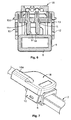
- reference numeral 1 denotes, as a whole, an electrical connector for a flexible LED strip seal 2 which can be seen in section in Fig. 2 .
- the LED seal 2 comprises, in the case of the embodiment shown here by way of example, a first channel-shaped body made of silicone material 3, on the base wall of which a PCB 4 is prearranged and carries a lined arrangement of LED light sources 5 (see Fig. 1 ) and conductive tracks (not visible in the drawings) for powering the LEDs 5.
- the LED seal 2 is prearranged with sets of four conductive pads 6 (two of which can be seen in Fig. 2 ) prearranged at predetermined intervals along the seal 2 so as to be able to cooperate with the contact elements of a connector according to the invention.
- the PCB 4 with the conductive tracks and the pads 6 is surrounded by a further (transparent) body made of silicone material 7 which fills the space defined within the channel-shaped body 3.
- the seal is cut to the desired length in such a way that four conductive pads 6 are arranged adjacent to one end thereof, and the connector according to the invention is mounted on said end so as to connect the four pads to four conductors forming part of the electric power cable (19 in Fig. 1 ).
- the connector is equipped with a hood 8, also made of silicone material, to be fitted on the end of the LED strip 2 (see Fig. 1 ).
- the hood 8 has planar walls 8a, 8b ( Fig. 3 ) which are mutually parallel and spaced in pairs, and a base wall 8c defining a cavity in which an end of the LED seal 2 is received, as can be seen in Figs 1 and 7 .
- the hood 8 also has a front shoulder 8d at its mouth.
- the connector according to the invention further comprises a metal body 9 for clamping the hood 8 after said hood has been fitted on the end of the LED seal 2.
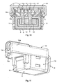
- the body 9 is formed of a thin steel sheet bent so as to define a lower wall 9a, two side walls 9b each prearranged with engagement teeth 9c projecting outwardly and formed by cutting and bending, and a base wall 9d having an outwardly bent upper edge (see also Fig. 4 and Fig. 11 ) and two auxiliary side clamping arms 9e.
- the teeth 9c constitute engagement elements for connection of a contact casing 10 made of plastics material to said metal body 9.
- the contact casing 10 has an upper wall 10a penetrated by four slits 11 for receiving four contact elements, as will be described in greater detail hereinafter.
- the plastics material body of the contact casing 10 further comprises two side walls 10b, each of which has spaced apertures 12, 13 arranged one above the other for selectively receiving the engagement teeth 9c of the metal body 9.
- the electrical connector according to the invention is initially prearranged in an inoperative state in which the engagement teeth 9c of the metal body 9 are engaged in the lower apertures 12 in the contact casing 10, the casing 10 being held on the metal body 9 in a raised inoperative position. As will be illustrated below, the casing 10 is then lowered into an operative position in which the engagement teeth 9c engage in the upper apertures 13 of the contact casing 10.
- Fig. 5 shows a sectional view of the contact casing 10 with the engagement teeth 9c of the metal body 9 engaged in the lower apertures 12.
- the four slits 11 which penetrate through the upper wall 10a of the casing 10 receive, with an interference fit, four thin conductive metal layers, for example formed of a copper alloy, each having a portion 14 constituting a contact element of the connector according to the invention which projects downwardly from the upper wall 10a of the contact casing 10.
- the thin metal layers defining the contact elements 14 have portions projecting upwardly from the upper wall 10a of the casing 10, denoted as a whole by reference numeral 15.
- the portions 15 have an axial incision extending from their end and defining a seat adapted to receive a respective electrical conductor.
- the two wings defined by said incision are shaped so as to cut and remove the insulating coating of the electrical conductor when it is inserted between them.
- the connector according to the invention also has a conductor casing 16 which is made of plastics material and has seats prearranged to receive four electrical conductors 17, one of such conductors 17 being used to power the LEDs 5 and the other three conductors 17 being used to transmit the signals corresponding to the red, yellow and blue colours of the LED light sources.
- a conductor casing 16 which is made of plastics material and has seats prearranged to receive four electrical conductors 17, one of such conductors 17 being used to power the LEDs 5 and the other three conductors 17 being used to transmit the signals corresponding to the red, yellow and blue colours of the LED light sources.
- the conductors 17 are first inserted into the seats in the conductor casing 16, each conductor being formed by a strand of conductive material surrounded by an insulating sheathing.
- the conductor casing 16 is then mounted in a seat defined between two end protrusions 10c projecting from the upper wall 10a of the contact casing 10. In this state, the portions 15 receive the conductors 17, automatically removing the insulating sheathing and placing the conductors themselves in electrical contact with the contact elements 14.
- the connector according to the invention lastly comprises a hood made of flexible material 18 which has a peripheral base edge 18b (see Figs 9 and 10 ) hooked over a projecting edge 10d of the contact casing 10 (see also Fig. 3 ) and which protects the upper part of the casing 10 and the conductor casing 16.
- the hood made of silicone material 18 also has a connection 18a with an opening 18c (see Fig. 11 ) for receiving the cable 19 (see Fig. 1 ) from which the conductors 17 emerge.
- the plate 8d of the hood made of silicone material 8 abuts a front face of the hood 18 (see Figs 7 and 8 ) and the base wall 9d of the metal body 9 is in contact with the base wall of the hood 8 (see Fig. 11 ).
- the connector according to the invention is initially prearranged with the conductors 17 mounted in the conductor casing 16 (see Figs 5 and 6 ), after which said conductor casing 16 is pushed into its final position on the contact casing 10 so as to create the electrical connection between the conductors 17 and the portions 15 of the contact elements of the connector, with automatic removal of the insulating sheathing of the conductors 17.
- the contact casing 10 is then prearranged in its raised inoperative position on the metal body 9 by engagement of the teeth 9c in the lower apertures 12 of the contact casing 10. In this state, one end of the LED strip 2, with the hood 8 fitted thereon, is mounted in the metal body 9 with an interference fit.
- the strip is inserted into the body 9 until the base wall 8c of the hood 8 abuts the base wall 9d of the metal body 9, the resilience of the side walls 9b and of the auxiliary arms 9e of the metal body 9 ensuring that the LED seal 2 is fixed in position.
- the device is thus in the state shown in Figs 5 and 6 .
- the contact casing 10 is pressed toward the base in such a way that the sharp ends of the contact elements 14 pierce the upper wall 8a of the hood made of silicone material 8 as well as the silicone material forming the body 7 ( Fig. 2 ) of the LED seal 2 until they come into contact with the conductive pads 6 prearranged on the PCB 4.
Landscapes
- Engineering & Computer Science (AREA)
- General Engineering & Computer Science (AREA)
- Connector Housings Or Holding Contact Members (AREA)
- Arrangement Of Elements, Cooling, Sealing, Or The Like Of Lighting Devices (AREA)
- Connections By Means Of Piercing Elements, Nuts, Or Screws (AREA)
- Connecting Device With Holders (AREA)
- Led Device Packages (AREA)
- Shielding Devices Or Components To Electric Or Magnetic Fields (AREA)
Claims (6)
- Elektrischer Verbinder für eine flexible LED-Streifendichtung, wobei die LED-Streifendichtung einen aus flexiblem Material hergestellten, zum Beispiel aus Silikonmaterial hergestellten Körper umfasst, in den eine Leiterplatte (4) einbezogen ist, die Leiterbahnen zur Stromversorgung der LEDs und als Kontaktanschlüsse dienende Anschlussflächen (6) trägt, dadurch gekennzeichnet, dass der Verbinder umfasst:- einen Metallkörper (9), der auf dem Streifen flexiblen Materials (2) anzubringen ist,- ein aus Kunststoffmaterial hergestelltes Kontaktgehäuse (10), das auf dem Metallkörper (9) angebracht ist und in Bezug auf den Metallkörper (9) von einer angehobenen nicht betriebsbereiten Position in eine abgesenkte betriebsbereite Position beweglich ist, und- eine Vielzahl von elektrischen Kontaktelementen (14), die durch das Kontaktgehäuse (10) getragen werden und durchstoßende Enden haben, die das Material des Streifens (2) durchstoßen und mit den Anschlussflächen (6) der Leiterplatte (4) in Kontakt kommen, wenn das Kontaktgehäuse (10) von seiner nicht betriebsbereiten Position in seine betriebsbereite Position bewegt wird,- wobei der Metallkörper (9) und das Kontaktgehäuse (10) zusammenwirkende Eingriffsmittel (9c, 13) haben, die sie in der betriebsbereiten Position halten, um dadurch den nötigen Kontaktdruck zwischen den Kontaktelementen (14) und den Anschlussflächen (6) sicherzustellen.
- Verbinder nach Anspruch 1, dadurch gekennzeichnet, dass die Kontaktelemente (14) Abschnitte von dünnen Metallblechen sind, die innerhalb einer Wand (10a) des Kontaktgehäuses (10) befestigt sind und jeweils das durchstoßende Ende, das von einer Seite der Wand (10a) hervorsteht, und ein entgegengesetztes Ende, das von der entgegengesetzten Seite der Wand hervorsteht und mit einer Auflage zum Aufnehmen eines entsprechenden Leiters (17) ausgebildet ist, haben.
- Verbinder nach Anspruch 2, dadurch gekennzeichnet, dass der Verbinder ferner umfasst: ein Leitergehäuse (16) zum Aufnehmen der mit den Kontaktelementen (14) zusammenwirkenden Leiter (17), wobei das Leitergehäuse (16) in einer Aufnahme in dem Kontaktgehäuse (10) montiert wird, und zwar in einer Position, in der die Leiter (17) in den Aufnahmen in den Kontaktelementen (14) aufgenommen werden.
- Verbinder nach Anspruch 1, dadurch gekennzeichnet, dass er ferner eine aus flexiblem Material hergestellte Kappe (8) umfasst, die auf ein Ende des Streifens aus flexiblem Material (2) aufzusetzen ist und im Voraus dafür eingerichtet ist, in dem Metallkörper (9) aufgenommen zu werden.
- Verbinder nach Anspruch 4, dadurch gekennzeichnet, dass der Metallkörper eine untere Wand (9a) und zwei Seitenwände (9b) hat, zwischen denen ein Ende des Streifens aus flexiblem Material aufgenommen wird und die auf ihren Außenflächen mit Eingriffszähnen (9c) versehen sind, die jeweils selektiv in zwei beabstandete Öffnungen (12, 13) eingreifen können, die übereinander angeordnet und in jeder der zwei Seitenwände (10b) des Kontaktgehäuses (10) ausgebildet sind.
- Verbinder nach Anspruch 5, dadurch gekennzeichnet, dass der Metallkörper (9) außerdem eine Basiswand (9d) umfasst, die dafür eingerichtet ist, eine Anschlagfläche für das Ende des Streifens aus flexiblem Material zu bilden, sobald dieser in dem Metallkörper (9) angebracht worden ist.
Applications Claiming Priority (2)
| Application Number | Priority Date | Filing Date | Title |
|---|---|---|---|
| ITTO2010A000341A IT1399569B1 (it) | 2010-04-22 | 2010-04-22 | Connettore elettrico per una guarnizione a striscia flessibile porta-led |
| PCT/EP2011/055614 WO2011131502A1 (en) | 2010-04-22 | 2011-04-11 | Electrical connector for flexible led strip seal |
Publications (2)
| Publication Number | Publication Date |
|---|---|
| EP2561579A1 EP2561579A1 (de) | 2013-02-27 |
| EP2561579B1 true EP2561579B1 (de) | 2014-06-11 |
Family
ID=43142668
Family Applications (1)
| Application Number | Title | Priority Date | Filing Date |
|---|---|---|---|
| EP11714033.5A Active EP2561579B1 (de) | 2010-04-22 | 2011-04-11 | Elektrischer steckverbinder für flexible led-streifendichtung |
Country Status (6)
| Country | Link |
|---|---|
| US (1) | US8814590B2 (de) |
| EP (1) | EP2561579B1 (de) |
| JP (1) | JP5637646B2 (de) |
| CN (1) | CN102844935B (de) |
| IT (1) | IT1399569B1 (de) |
| WO (1) | WO2011131502A1 (de) |
Families Citing this family (14)
| Publication number | Priority date | Publication date | Assignee | Title |
|---|---|---|---|---|
| US9450395B2 (en) * | 2013-07-04 | 2016-09-20 | Tower Manufacturing | Manual reset ground fault circuit interruptor (GFCI) with a quick connect load input |
| DE102013012251A1 (de) * | 2013-07-24 | 2015-01-29 | Erni Production Gmbh & Co. Kg | Terminal zur Kontaktierung eines elektrischen Leiters |
| DE202014106102U1 (de) * | 2014-12-17 | 2016-03-18 | Zumtobel Lighting Gmbh | Geräteträger und Leuchtmittelträger für eine Lichtbandleuchte |
| PT3109535T (pt) * | 2015-06-23 | 2018-03-22 | Usm Holding Ag | Sistema de móvel com um módulo consumidor para aplicação num tubo de uma estrutura tubular tridimensional de sustentação |
| CN107293864B (zh) * | 2016-04-01 | 2019-06-28 | 安费诺亮泰企业股份有限公司 | 用于软性光源灯条的连接器结构 |
| CN107293865B (zh) * | 2016-04-01 | 2020-05-15 | 安费诺亮泰企业股份有限公司 | 具双向夹持结构的连接器组件 |
| TWI586057B (zh) * | 2016-04-08 | 2017-06-01 | 安費諾亮泰企業股份有限公司 | 用於軟性光源燈條的連接器結構 |
| US9647349B1 (en) * | 2016-06-02 | 2017-05-09 | Elemental LED, Inc. | Through-insulation strip light connector |
| IT201600100619A1 (it) * | 2016-10-06 | 2018-04-06 | Techno Group S R L | Dispositivo per l'alimentazione elettrica di barre di illuminazione |
| US10211552B2 (en) * | 2016-10-21 | 2019-02-19 | Foxconn Interconnect Technology Limited | Cable connector assembly having space-saving connection between cable wire conductors and contact terminating portions |
| US10941930B2 (en) | 2018-11-27 | 2021-03-09 | Kichler Lighting, LLC | Radially symmetric electrical connector |
| US11043762B1 (en) | 2020-03-31 | 2021-06-22 | Gjak, Llc | LED light strip with terminal block connector |
| JP7811361B2 (ja) * | 2022-07-01 | 2026-02-05 | 日本航空電子工業株式会社 | コネクタ |
| CN221035651U (zh) * | 2023-09-27 | 2024-05-28 | 深圳市思坎普科技有限公司 | 一种灯带连接组件及其灯带 |
Family Cites Families (14)
| Publication number | Priority date | Publication date | Assignee | Title |
|---|---|---|---|---|
| JPS542188U (de) * | 1977-06-08 | 1979-01-09 | ||
| JPS5748303Y2 (de) * | 1978-10-25 | 1982-10-22 | ||
| US6158882A (en) | 1998-06-30 | 2000-12-12 | Emteq, Inc. | LED semiconductor lighting system |
| CN1243343A (zh) * | 1998-07-28 | 2000-02-02 | 法玛通国际连接器公司 | 带有密封的穿透绝缘体的楔形连接件 |
| CA2249084A1 (en) * | 1998-09-29 | 2000-03-29 | Framatome Connectors Canada Inc. | Insulation-piercing connector for connecting insulated cables to a led light strip |
| US6660935B2 (en) * | 2001-05-25 | 2003-12-09 | Gelcore Llc | LED extrusion light engine and connector therefor |
| JP3102290U (ja) * | 2003-12-16 | 2004-07-02 | 樊 邦弘 | 軟質ケーブルライト |
| US7210957B2 (en) * | 2004-04-06 | 2007-05-01 | Lumination Llc | Flexible high-power LED lighting system |
| CN2784721Y (zh) * | 2004-12-18 | 2006-05-31 | 樊邦弘 | 一种新型软管灯 |
| US7160140B1 (en) * | 2005-07-13 | 2007-01-09 | Gelcore Llc | LED string light engine |
| DE102006045808B4 (de) * | 2006-09-26 | 2016-02-18 | Erni Production Gmbh & Co. Kg | Steckverbinder mit Zugentlastung |
| CN200982547Y (zh) * | 2006-10-24 | 2007-11-28 | 邵树发 | Led排灯 |
| US20080137377A1 (en) * | 2006-12-11 | 2008-06-12 | Gelcore, Llc | Led light engine and method of manufacturing |
| CN201187701Y (zh) * | 2008-04-02 | 2009-01-28 | 鹤山丽得电子实业有限公司 | 一种带灯灯座结构 |
-
2010
- 2010-04-22 IT ITTO2010A000341A patent/IT1399569B1/it active
-
2011
- 2011-04-11 EP EP11714033.5A patent/EP2561579B1/de active Active
- 2011-04-11 WO PCT/EP2011/055614 patent/WO2011131502A1/en not_active Ceased
- 2011-04-11 CN CN201180019238.3A patent/CN102844935B/zh active Active
- 2011-04-11 US US13/642,448 patent/US8814590B2/en active Active
- 2011-04-11 JP JP2013505395A patent/JP5637646B2/ja not_active Expired - Fee Related
Also Published As
| Publication number | Publication date |
|---|---|
| IT1399569B1 (it) | 2013-04-19 |
| ITTO20100341A1 (it) | 2011-10-23 |
| CN102844935B (zh) | 2016-06-29 |
| JP2013529353A (ja) | 2013-07-18 |
| US20130034988A1 (en) | 2013-02-07 |
| CN102844935A (zh) | 2012-12-26 |
| EP2561579A1 (de) | 2013-02-27 |
| US8814590B2 (en) | 2014-08-26 |
| WO2011131502A1 (en) | 2011-10-27 |
| JP5637646B2 (ja) | 2014-12-10 |
Similar Documents
| Publication | Publication Date | Title |
|---|---|---|
| US8814590B2 (en) | Electrical connector for flexible LED strip seal | |
| CN101969169B (zh) | 线对板连接器 | |
| US9647349B1 (en) | Through-insulation strip light connector | |
| CN104934735A (zh) | 按钮电源懒式连接器 | |
| EP2416451B1 (de) | Elektrischer Steckverbinder | |
| EP1738436B1 (de) | Kappe, abschlussbaugruppe und gehäusebaugruppe für einen modularen telekom-verbindungsstecker | |
| EP2509171B1 (de) | Leiteranschlussstecker, Steckverbinder und Set aus Leiteranschlussstecker und Steckverbinder | |
| EP1965123A1 (de) | Beleuchtungsvorrichtungskabel und Beleuchtungsvorrichtung damit | |
| HU225335B1 (en) | Lighting device | |
| TW576572U (en) | Cable connector assembly with IDC contacts | |
| EP1443605A3 (de) | Leistungsverbinder mit vertikalen Wechselstromstiftkontakten | |
| US20120264337A1 (en) | Cable Connector | |
| EP3270053B1 (de) | Gehäuse für beleuchtungsvorrichtungen, zugehörige beleuchtungsvorrichtung und verfahren | |
| WO2013108928A1 (en) | Flat circuit body with terminal and manufacturing method thereof | |
| WO2007062327A3 (en) | Releasable wire connector | |
| US6454582B2 (en) | Wiring unit | |
| EP2803117B1 (de) | Verfahren zur herstellung einer flexiblen elektrischen schnur und verbinder dafür | |
| CN110676621B (zh) | 连接器 | |
| WO2006040183A8 (de) | Dichtungselement für flexible flat cable (ffc), fpc und andere flache leitungen mit und ohne rundleiter | |
| WO2008099093A8 (fr) | Prise de raccordement a montage simplifie pour cable multiconducteur | |
| CN102713418A (zh) | 照明装置和用于接触照明装置的方法 | |
| JP2017045094A5 (de) | ||
| WO2006120373A3 (en) | Electrical wire connector | |
| CN112467430A (zh) | 电线串接结构 | |
| EP2650974B1 (de) | Klemmenblock und elektronikeinheit |
Legal Events
| Date | Code | Title | Description |
|---|---|---|---|
| PUAI | Public reference made under article 153(3) epc to a published international application that has entered the european phase |
Free format text: ORIGINAL CODE: 0009012 |
|
| 17P | Request for examination filed |
Effective date: 20121019 |
|
| AK | Designated contracting states |
Kind code of ref document: A1 Designated state(s): AL AT BE BG CH CY CZ DE DK EE ES FI FR GB GR HR HU IE IS IT LI LT LU LV MC MK MT NL NO PL PT RO RS SE SI SK SM TR |
|
| DAX | Request for extension of the european patent (deleted) | ||
| GRAP | Despatch of communication of intention to grant a patent |
Free format text: ORIGINAL CODE: EPIDOSNIGR1 |
|
| INTG | Intention to grant announced |
Effective date: 20140124 |
|
| GRAS | Grant fee paid |
Free format text: ORIGINAL CODE: EPIDOSNIGR3 |
|
| GRAA | (expected) grant |
Free format text: ORIGINAL CODE: 0009210 |
|
| AK | Designated contracting states |
Kind code of ref document: B1 Designated state(s): AL AT BE BG CH CY CZ DE DK EE ES FI FR GB GR HR HU IE IS IT LI LT LU LV MC MK MT NL NO PL PT RO RS SE SI SK SM TR |
|
| REG | Reference to a national code |
Ref country code: GB Ref legal event code: FG4D |
|
| REG | Reference to a national code |
Ref country code: CH Ref legal event code: EP |
|
| REG | Reference to a national code |
Ref country code: IE Ref legal event code: FG4D |
|
| REG | Reference to a national code |
Ref country code: AT Ref legal event code: REF Ref document number: 672629 Country of ref document: AT Kind code of ref document: T Effective date: 20140715 |
|
| REG | Reference to a national code |
Ref country code: DE Ref legal event code: R096 Ref document number: 602011007604 Country of ref document: DE Effective date: 20140724 |
|
| REG | Reference to a national code |
Ref country code: NL Ref legal event code: T3 |
|
| PG25 | Lapsed in a contracting state [announced via postgrant information from national office to epo] |
Ref country code: NO Free format text: LAPSE BECAUSE OF FAILURE TO SUBMIT A TRANSLATION OF THE DESCRIPTION OR TO PAY THE FEE WITHIN THE PRESCRIBED TIME-LIMIT Effective date: 20140911 Ref country code: FI Free format text: LAPSE BECAUSE OF FAILURE TO SUBMIT A TRANSLATION OF THE DESCRIPTION OR TO PAY THE FEE WITHIN THE PRESCRIBED TIME-LIMIT Effective date: 20140611 Ref country code: GR Free format text: LAPSE BECAUSE OF FAILURE TO SUBMIT A TRANSLATION OF THE DESCRIPTION OR TO PAY THE FEE WITHIN THE PRESCRIBED TIME-LIMIT Effective date: 20140912 Ref country code: LT Free format text: LAPSE BECAUSE OF FAILURE TO SUBMIT A TRANSLATION OF THE DESCRIPTION OR TO PAY THE FEE WITHIN THE PRESCRIBED TIME-LIMIT Effective date: 20140611 |
|
| REG | Reference to a national code |
Ref country code: AT Ref legal event code: MK05 Ref document number: 672629 Country of ref document: AT Kind code of ref document: T Effective date: 20140611 |
|
| REG | Reference to a national code |
Ref country code: LT Ref legal event code: MG4D |
|
| PG25 | Lapsed in a contracting state [announced via postgrant information from national office to epo] |
Ref country code: HR Free format text: LAPSE BECAUSE OF FAILURE TO SUBMIT A TRANSLATION OF THE DESCRIPTION OR TO PAY THE FEE WITHIN THE PRESCRIBED TIME-LIMIT Effective date: 20140611 Ref country code: LV Free format text: LAPSE BECAUSE OF FAILURE TO SUBMIT A TRANSLATION OF THE DESCRIPTION OR TO PAY THE FEE WITHIN THE PRESCRIBED TIME-LIMIT Effective date: 20140611 Ref country code: RS Free format text: LAPSE BECAUSE OF FAILURE TO SUBMIT A TRANSLATION OF THE DESCRIPTION OR TO PAY THE FEE WITHIN THE PRESCRIBED TIME-LIMIT Effective date: 20140611 Ref country code: SE Free format text: LAPSE BECAUSE OF FAILURE TO SUBMIT A TRANSLATION OF THE DESCRIPTION OR TO PAY THE FEE WITHIN THE PRESCRIBED TIME-LIMIT Effective date: 20140611 |
|
| PG25 | Lapsed in a contracting state [announced via postgrant information from national office to epo] |
Ref country code: EE Free format text: LAPSE BECAUSE OF FAILURE TO SUBMIT A TRANSLATION OF THE DESCRIPTION OR TO PAY THE FEE WITHIN THE PRESCRIBED TIME-LIMIT Effective date: 20140611 Ref country code: SK Free format text: LAPSE BECAUSE OF FAILURE TO SUBMIT A TRANSLATION OF THE DESCRIPTION OR TO PAY THE FEE WITHIN THE PRESCRIBED TIME-LIMIT Effective date: 20140611 Ref country code: RO Free format text: LAPSE BECAUSE OF FAILURE TO SUBMIT A TRANSLATION OF THE DESCRIPTION OR TO PAY THE FEE WITHIN THE PRESCRIBED TIME-LIMIT Effective date: 20140611 Ref country code: PT Free format text: LAPSE BECAUSE OF FAILURE TO SUBMIT A TRANSLATION OF THE DESCRIPTION OR TO PAY THE FEE WITHIN THE PRESCRIBED TIME-LIMIT Effective date: 20141013 Ref country code: CZ Free format text: LAPSE BECAUSE OF FAILURE TO SUBMIT A TRANSLATION OF THE DESCRIPTION OR TO PAY THE FEE WITHIN THE PRESCRIBED TIME-LIMIT Effective date: 20140611 Ref country code: ES Free format text: LAPSE BECAUSE OF FAILURE TO SUBMIT A TRANSLATION OF THE DESCRIPTION OR TO PAY THE FEE WITHIN THE PRESCRIBED TIME-LIMIT Effective date: 20140611 |
|
| PG25 | Lapsed in a contracting state [announced via postgrant information from national office to epo] |
Ref country code: IS Free format text: LAPSE BECAUSE OF FAILURE TO SUBMIT A TRANSLATION OF THE DESCRIPTION OR TO PAY THE FEE WITHIN THE PRESCRIBED TIME-LIMIT Effective date: 20141011 Ref country code: AT Free format text: LAPSE BECAUSE OF FAILURE TO SUBMIT A TRANSLATION OF THE DESCRIPTION OR TO PAY THE FEE WITHIN THE PRESCRIBED TIME-LIMIT Effective date: 20140611 Ref country code: PL Free format text: LAPSE BECAUSE OF FAILURE TO SUBMIT A TRANSLATION OF THE DESCRIPTION OR TO PAY THE FEE WITHIN THE PRESCRIBED TIME-LIMIT Effective date: 20140611 |
|
| REG | Reference to a national code |
Ref country code: DE Ref legal event code: R097 Ref document number: 602011007604 Country of ref document: DE |
|
| PLBE | No opposition filed within time limit |
Free format text: ORIGINAL CODE: 0009261 |
|
| STAA | Information on the status of an ep patent application or granted ep patent |
Free format text: STATUS: NO OPPOSITION FILED WITHIN TIME LIMIT |
|
| PG25 | Lapsed in a contracting state [announced via postgrant information from national office to epo] |
Ref country code: DK Free format text: LAPSE BECAUSE OF FAILURE TO SUBMIT A TRANSLATION OF THE DESCRIPTION OR TO PAY THE FEE WITHIN THE PRESCRIBED TIME-LIMIT Effective date: 20140611 |
|
| 26N | No opposition filed |
Effective date: 20150312 |
|
| REG | Reference to a national code |
Ref country code: DE Ref legal event code: R097 Ref document number: 602011007604 Country of ref document: DE Effective date: 20150312 |
|
| PG25 | Lapsed in a contracting state [announced via postgrant information from national office to epo] |
Ref country code: BE Free format text: LAPSE BECAUSE OF FAILURE TO SUBMIT A TRANSLATION OF THE DESCRIPTION OR TO PAY THE FEE WITHIN THE PRESCRIBED TIME-LIMIT Effective date: 20140611 |
|
| PG25 | Lapsed in a contracting state [announced via postgrant information from national office to epo] |
Ref country code: SI Free format text: LAPSE BECAUSE OF FAILURE TO SUBMIT A TRANSLATION OF THE DESCRIPTION OR TO PAY THE FEE WITHIN THE PRESCRIBED TIME-LIMIT Effective date: 20140611 |
|
| PG25 | Lapsed in a contracting state [announced via postgrant information from national office to epo] |
Ref country code: LU Free format text: LAPSE BECAUSE OF FAILURE TO SUBMIT A TRANSLATION OF THE DESCRIPTION OR TO PAY THE FEE WITHIN THE PRESCRIBED TIME-LIMIT Effective date: 20150411 Ref country code: MC Free format text: LAPSE BECAUSE OF FAILURE TO SUBMIT A TRANSLATION OF THE DESCRIPTION OR TO PAY THE FEE WITHIN THE PRESCRIBED TIME-LIMIT Effective date: 20140611 |
|
| REG | Reference to a national code |
Ref country code: CH Ref legal event code: PL |
|
| GBPC | Gb: european patent ceased through non-payment of renewal fee |
Effective date: 20150411 |
|
| REG | Reference to a national code |
Ref country code: IE Ref legal event code: MM4A |
|
| PG25 | Lapsed in a contracting state [announced via postgrant information from national office to epo] |
Ref country code: LI Free format text: LAPSE BECAUSE OF NON-PAYMENT OF DUE FEES Effective date: 20150430 Ref country code: GB Free format text: LAPSE BECAUSE OF NON-PAYMENT OF DUE FEES Effective date: 20150411 Ref country code: CH Free format text: LAPSE BECAUSE OF NON-PAYMENT OF DUE FEES Effective date: 20150430 |
|
| REG | Reference to a national code |
Ref country code: FR Ref legal event code: PLFP Year of fee payment: 6 |
|
| PG25 | Lapsed in a contracting state [announced via postgrant information from national office to epo] |
Ref country code: IE Free format text: LAPSE BECAUSE OF NON-PAYMENT OF DUE FEES Effective date: 20150411 |
|
| PG25 | Lapsed in a contracting state [announced via postgrant information from national office to epo] |
Ref country code: MT Free format text: LAPSE BECAUSE OF FAILURE TO SUBMIT A TRANSLATION OF THE DESCRIPTION OR TO PAY THE FEE WITHIN THE PRESCRIBED TIME-LIMIT Effective date: 20140611 |
|
| REG | Reference to a national code |
Ref country code: FR Ref legal event code: PLFP Year of fee payment: 7 |
|
| PG25 | Lapsed in a contracting state [announced via postgrant information from national office to epo] |
Ref country code: SM Free format text: LAPSE BECAUSE OF FAILURE TO SUBMIT A TRANSLATION OF THE DESCRIPTION OR TO PAY THE FEE WITHIN THE PRESCRIBED TIME-LIMIT Effective date: 20140611 Ref country code: HU Free format text: LAPSE BECAUSE OF FAILURE TO SUBMIT A TRANSLATION OF THE DESCRIPTION OR TO PAY THE FEE WITHIN THE PRESCRIBED TIME-LIMIT; INVALID AB INITIO Effective date: 20110411 Ref country code: BG Free format text: LAPSE BECAUSE OF FAILURE TO SUBMIT A TRANSLATION OF THE DESCRIPTION OR TO PAY THE FEE WITHIN THE PRESCRIBED TIME-LIMIT Effective date: 20140611 |
|
| PG25 | Lapsed in a contracting state [announced via postgrant information from national office to epo] |
Ref country code: CY Free format text: LAPSE BECAUSE OF FAILURE TO SUBMIT A TRANSLATION OF THE DESCRIPTION OR TO PAY THE FEE WITHIN THE PRESCRIBED TIME-LIMIT Effective date: 20140611 |
|
| PG25 | Lapsed in a contracting state [announced via postgrant information from national office to epo] |
Ref country code: TR Free format text: LAPSE BECAUSE OF FAILURE TO SUBMIT A TRANSLATION OF THE DESCRIPTION OR TO PAY THE FEE WITHIN THE PRESCRIBED TIME-LIMIT Effective date: 20140611 |
|
| REG | Reference to a national code |
Ref country code: FR Ref legal event code: PLFP Year of fee payment: 8 |
|
| PG25 | Lapsed in a contracting state [announced via postgrant information from national office to epo] |
Ref country code: MK Free format text: LAPSE BECAUSE OF FAILURE TO SUBMIT A TRANSLATION OF THE DESCRIPTION OR TO PAY THE FEE WITHIN THE PRESCRIBED TIME-LIMIT Effective date: 20140611 |
|
| PG25 | Lapsed in a contracting state [announced via postgrant information from national office to epo] |
Ref country code: AL Free format text: LAPSE BECAUSE OF FAILURE TO SUBMIT A TRANSLATION OF THE DESCRIPTION OR TO PAY THE FEE WITHIN THE PRESCRIBED TIME-LIMIT Effective date: 20140611 |
|
| PGFP | Annual fee paid to national office [announced via postgrant information from national office to epo] |
Ref country code: NL Payment date: 20200417 Year of fee payment: 10 |
|
| REG | Reference to a national code |
Ref country code: NL Ref legal event code: MM Effective date: 20210501 |
|
| PG25 | Lapsed in a contracting state [announced via postgrant information from national office to epo] |
Ref country code: NL Free format text: LAPSE BECAUSE OF NON-PAYMENT OF DUE FEES Effective date: 20210501 |
|
| PGFP | Annual fee paid to national office [announced via postgrant information from national office to epo] |
Ref country code: FR Payment date: 20240308 Year of fee payment: 14 |
|
| PGFP | Annual fee paid to national office [announced via postgrant information from national office to epo] |
Ref country code: DE Payment date: 20250305 Year of fee payment: 15 |
|
| PG25 | Lapsed in a contracting state [announced via postgrant information from national office to epo] |
Ref country code: FR Free format text: LAPSE BECAUSE OF NON-PAYMENT OF DUE FEES Effective date: 20250430 |
|
| PGFP | Annual fee paid to national office [announced via postgrant information from national office to epo] |
Ref country code: IT Payment date: 20260320 Year of fee payment: 16 |