EP2561531B1 - Einspeisemodul - Google Patents
Einspeisemodul Download PDFInfo
- Publication number
- EP2561531B1 EP2561531B1 EP11714042.6A EP11714042A EP2561531B1 EP 2561531 B1 EP2561531 B1 EP 2561531B1 EP 11714042 A EP11714042 A EP 11714042A EP 2561531 B1 EP2561531 B1 EP 2561531B1
- Authority
- EP
- European Patent Office
- Prior art keywords
- housing
- feed module
- contact
- fuse
- printed circuit
- Prior art date
- Legal status (The legal status is an assumption and is not a legal conclusion. Google has not performed a legal analysis and makes no representation as to the accuracy of the status listed.)
- Active
Links
Images




Classifications
-
- H—ELECTRICITY
- H05—ELECTRIC TECHNIQUES NOT OTHERWISE PROVIDED FOR
- H05K—PRINTED CIRCUITS; CASINGS OR CONSTRUCTIONAL DETAILS OF ELECTRIC APPARATUS; MANUFACTURE OF ASSEMBLAGES OF ELECTRICAL COMPONENTS
- H05K1/00—Printed circuits
- H05K1/02—Details
- H05K1/0213—Electrical arrangements not otherwise provided for
- H05K1/0263—High current adaptations, e.g. printed high current conductors or using auxiliary non-printed means; Fine and coarse circuit patterns on one circuit board
-
- H—ELECTRICITY
- H01—ELECTRIC ELEMENTS
- H01H—ELECTRIC SWITCHES; RELAYS; SELECTORS; EMERGENCY PROTECTIVE DEVICES
- H01H85/00—Protective devices in which the current flows through a part of fusible material and this current is interrupted by displacement of the fusible material when this current becomes excessive
- H01H85/02—Details
- H01H85/20—Bases for supporting the fuse; Separate parts thereof
-
- H—ELECTRICITY
- H01—ELECTRIC ELEMENTS
- H01R—ELECTRICALLY-CONDUCTIVE CONNECTIONS; STRUCTURAL ASSOCIATIONS OF A PLURALITY OF MUTUALLY-INSULATED ELECTRICAL CONNECTING ELEMENTS; COUPLING DEVICES; CURRENT COLLECTORS
- H01R9/00—Structural associations of a plurality of mutually-insulated electrical connecting elements, e.g. terminal strips or terminal blocks; Terminals or binding posts mounted upon a base or in a case; Bases therefor
- H01R9/22—Bases, e.g. strip, block, panel
- H01R9/24—Terminal blocks
- H01R9/2458—Electrical interconnections between terminal blocks
-
- H—ELECTRICITY
- H01—ELECTRIC ELEMENTS
- H01R—ELECTRICALLY-CONDUCTIVE CONNECTIONS; STRUCTURAL ASSOCIATIONS OF A PLURALITY OF MUTUALLY-INSULATED ELECTRICAL CONNECTING ELEMENTS; COUPLING DEVICES; CURRENT COLLECTORS
- H01R9/00—Structural associations of a plurality of mutually-insulated electrical connecting elements, e.g. terminal strips or terminal blocks; Terminals or binding posts mounted upon a base or in a case; Bases therefor
- H01R9/22—Bases, e.g. strip, block, panel
- H01R9/24—Terminal blocks
- H01R9/26—Clip-on terminal blocks for side-by-side rail- or strip-mounting
- H01R9/2675—Electrical interconnections between two blocks, e.g. by means of busbars
-
- H—ELECTRICITY
- H05—ELECTRIC TECHNIQUES NOT OTHERWISE PROVIDED FOR
- H05K—PRINTED CIRCUITS; CASINGS OR CONSTRUCTIONAL DETAILS OF ELECTRIC APPARATUS; MANUFACTURE OF ASSEMBLAGES OF ELECTRICAL COMPONENTS
- H05K1/00—Printed circuits
- H05K1/02—Details
- H05K1/14—Structural association of two or more printed circuits
- H05K1/145—Arrangements wherein electric components are disposed between and simultaneously connected to two planar printed circuit boards, e.g. Cordwood modules
Definitions
- the invention relates to a feed module for feeding electrical current into a drive module, wherein the feed module has a first Anschlußköntakt and a second terminal contact, wherein the first terminal contact is designed to connect the feed module to the drive module, and the second terminal contact is designed, a compound to provide a power supply.
- a fuse distribution box is known, can be fed via the power, wherein two printed circuit boards are provided, on each of which terminals are arranged. Between the terminals then the fuse elements are connected, which in turn are arranged on the one circuit board in order to limit the current flow between the terminal contacts.
- the US 4,989,118 shows a circuit breaker, in which several circuit breakers could be connected together via a rail.
- an improved feed module can be provided in that the feed module has a first terminal contact and a second terminal contact, wherein the first terminal contact connects the feed module to the drive module and the second terminal contact provides a connection to a power supply, wherein between the first Terminal contact and the second terminal contact a fuse element is arranged, which is connected to the two terminal contacts and limits a current flow between the first terminal contact and the second terminal contact.
- the drive module can be modularly secured by the securing element according to various different standards.
- the first connection contact is arranged on a first printed circuit board and the second connection contact is arranged on a second printed circuit board, wherein the fuse element is arranged between the first printed circuit board and the second printed circuit board and connected to the printed circuit board. In this way, the fuse elements can be easily mounted in the feed module.
- the second connection contact has a contact slide with a contact slide and a contact bridge, which is actuated by the contact slide and engages in a further feed module in order to provide an electrical connection to the further feed module.
- a connection can be created easily and quickly from the feed module to a further feed module, which is advantageous in particular when assembling a plurality of drive modules to a multi-axis drive system.
- the securing element is connected to a bus bar, which is connected to one of the two circuit boards and provides an electrical connection from the fuse element to one of the two circuit boards.
- the bus bar is Z-shaped and connects a plate with one of the two circuit boards. In this way, the spatial arrangement of the plate within a housing of the supply module can be easily determined.
- the fuse element comprises a fuse body and a fuse holder, wherein the fuse holder is attached to the plate ah and connected to the busbar, and wherein the fuse holder secures the fuse body in the housing of the feed module. In this way, a vibration-resistant attachment of the fuse body is provided in the feed module.
- the first printed circuit board is connected to the second printed circuit board by means of a connecting pin.
- the two circuit boards can be easily supported against each other as well as provided by the first connection contact to the second terminal contact a connection without fuse element.
- the housing of the feed module has a first, a second and a third housing part, wherein the first housing part can be connected to both the second and the third housing part.
- the three housing parts together can form a first housing, wherein by means of the first housing part and the third housing part, a second housing can be formed, which is designed as a feed module without fuse element.
- the second housing part is arranged between the first and the third housing part, wherein the first housing part comprises a first crenellated area, which faces the second housing part.
- the second housing part comprises a second crenellated area, which is designed such that the second crenellated area engages in the first crenellated area.
- the housing has a lid which is arranged laterally on the housing in a region of the securing element, wherein the lid can be opened from the outside and reclosed and covers the securing element.
- a fan is arranged in the feed module, which is designed to convey cooling air through the feed module. In this way, an operating temperature of the fuse elements can be ensured by a forced cooling by means of the fan.
- FIG. 1 shows a perspective view of a first feed module 10 to a drive module 11 in the mounted state.
- the drive module 11 is designed as a servo amplifier and serves to drive a servomotor, not shown.
- the feed module 10 is arranged.
- the first supply module 10 comprises a housing 53, on the front side of which a plurality of contact slides 13, 14, 15 are arranged, which form the connection contacts 110, 111, 112 of the first supply module.
- the contact slides 13, 14, 15 comprise contact bridges 16, wherein the contact slides 13, 14, 15 are moved to the left and right at the front of the first feed module 10 can. Furthermore, the contact slides 13, 14, 15 a plurality of screw 6.
- the housing 53 of the first feed module 10 is formed in three parts and comprises a first housing part 50, on which the contact slides 13, 14, 15 are arranged, a second housing part 51 and a third housing part 52, wherein the second housing part 51 between the. first housing part 50 and the third housing part 52 is arranged.
- the housing 53 further comprises a plurality of contact openings 70, which are designed to receive the contact bridges 16 of a further supply module.
- the housing 53 On the rear side, the housing 53 has a latching element 55, which engages in a latching nose 58 of the drive module 11.
- FIG. 2 shows a front view of the first feed module 10.
- the contact slides 13, 14, 15 are shown in an extended, actuated state in which the contact bridges 16 protrude from the housing 53 of the first feed module 10 to engage in another feed module and contact elements 19 of another Contact feed module.
- the contact slides 13, 14, 15 are displaced to the right, so that the contact bridges 16 are inserted in the housing 53 of the first feed module 10. If the feed module 10 is mounted in a composite with a plurality of drive modules and other feed modules, the feed module 10 is plugged onto the drive module 11, wherein the locking elements 55 engage in detents 58 of the drive module 11 and the first feed module 10 reversibly attached to the drive module 11.
- the contact slides 13, 14, 15 are moved to the left after latching of the first feed module 10 on the drive module 11, so that the contact bridges 16 in a further feed module protrude into and engage there in contact elements, not shown.
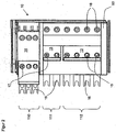
- FIG. 3 shows the in FIG. 2 illustrated front view of the first feed module 10 without the first housing part 50, which carries the contact slide 13,14,15.
- a first printed circuit board 20 which is arranged parallel to the plane of the drawing, a plurality of screw receptacles 18 are arranged with fastening screws 17.
- the fastening screws 17 pass through the oblong holes 22 of the contact bridges 16 and secure them to the first printed circuit board 20.
- the contact bridges 16 can be displaced by the contact slides 13, 14, 15, the fastening screw 17 being released in the oblong hole 22 for displacement is.
- the fastening screw 17 is tightened by the screw 6, so that the contact bridge 16 is reliably fixed. This allows a quick assembly and disassembly of the first feed module 10th
- the first printed circuit board 20 also has fastening points 23 which serve to connect the first printed circuit board 20 to a second printed circuit board 21 arranged behind it.
- a plurality of contact elements 19 are arranged on the first circuit board 20, into which the contact bridge 16 of a further supply module can engage, so as to provide a connection to the further supply module.
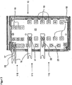
- FIG. 4 shows a side view of the first feed module 10 in a partially assembled state.
- the first printed circuit board 20 and the third housing part 52 parallel to the first printed circuit board 20 a second printed circuit board 21 is arranged. It is in the FIG. 4 the second circuit board 21 hidden by the third housing part 52.
- the printed circuit boards 20, 21 are arranged parallel to the front and back of the housing 53 and fixed in the housing 53 by means of fastening elements 38.
- a plate 40 Perpendicular to the two printed circuit boards 20, 21, a plate 40 is arranged, which has electrically insulating material and for fixing the busbars 35, 36 and arranged on the opposite side of the plate 40 and in FIG. 5 illustrated fuse elements 30 is used.
- a first bus bar 35 arranged on the first circuit board 20 is Z-shaped and is fastened at one end to an angle element 39 by means of a connecting screw 24. At the other end, the first busbar 35 has a receptacle 37.
- the Z-shaped design of the first busbar 35 serves to define a safety distance d between the busbars 35, 36 and the fuse elements 30. In this way, it is ensured that the necessary for air safety distance d is maintained corresponding to a voltage applied to the fuse element 30 and the insulation of the fuse element 30. Due to the Z-shaped configuration, the receptacle 37 for fixing the securing element 30 in the height (x-direction) can be structurally fixed to the plate 40, so that the available installation space in the housing 53 is optimally utilized. Furthermore, the space depth in the z-direction of the housing 53 is optimally utilized by the Z-shaped design of the first busbar 35 in order to ensure a narrow design of the feed module 10.
- a second bus bar 36 is plate-shaped and connects an output side of the fuse elements 30 and the receptacle 37 with the second printed circuit board 21.
- the second busbars 36 are secured to the second printed circuit board 21 by means of the connecting screws 24 and angle elements, not shown.
- On the back of the plate 40 are, as in FIG. 5 and 6 shown, the fuse elements 30 are arranged.
- the receptacle 37 is electrically connected to the fuse element 30 through the plate 40.
- connecting contacts 120, 121, 122 are provided to the first feed module 10 in the assembled state with the drive module 11, as in FIG. 1 shown to connect. In this case, a first connection contact 120 makes available the mains voltage tapped via the first contact slide 13.
- a second connection contact 121 serves for a DC link connection for the energy exchange between the individual drive modules 11.
- a connection for the second connection contact 121 is provided via the third contact slide 15 to further supply modules.
- a third terminal contact 122 is connected by means of connecting pin 45 with the second contact slide 14 and provides an auxiliary voltage in the form of DC voltage for supplying the drive module 11 or for control, eg a brake, a thermal contact and / or. For digital inputs and outputs ready. Due to the low control currents in it, a hedge according to the UL standard is not provided. Further, the third terminal contact 122 and the second contact slide 14 is connected by the connecting pin 45 low resistance.
- FIG. 5 shows a perspective view of the first feed module 10. Here is a back of the FIG. 4 shown.
- the securing elements 30 are arranged on the plate 40.
- the fuse elements 30 have a different size depending on the current level to be protected.
- the first fuse bodies 32 arranged below to protect the first connection contact 120 are smaller than the second fuse bodies 3i arranged above the first fuse bodies for securing the DC link connection.
- the corresponding fuse holder 33, 34 are formed and fixed to the plate 40.
- the fuse holders 33, 34 are spaced from each other in the x-direction on the plate 40, that a Üerhus of voltages to the adjacently arranged fuse holder 33, 34 is avoided and a necessary for the applied voltages safety distance d is met.
- the fuse holder 33, 34 engage in the back of the receptacle 37 and are thereby connected to the busbars 35, 36.
- fuses electronic fuses, self-resetting fuses, motor protection switches or circuit breakers are also conceivable.
- the connecting bolts 45 are fastened by means of connecting screws 24 to the first printed circuit board 20.
- the connecting bolt 45 has a thread which engages in the mounted state in a Bolzenverschraubung 46, which is arranged on the inside of the second printed circuit board 21.
- the above and below the housing arranged connecting pin 45 further support the two circuit boards 20, 21 against each other and secure them in the housing 53. Further, the plate 40 for better support of the printed circuit boards 20, 21 connected to the printed circuit boards 20, 21.
- the first busbar 35 is also S-shaped in addition to the Z-shaped configuration in order to arrange the arrangement of the fuse holder 33, 34 on the plate 40 in the y-direction in terms of space. Depending on the design of the S-shape of the busbar 35, the position of the plate in the y-direction can be adapted constructively.
- FIG. 6 shows a perspective view of the feeder module 10 in a partially assembled state.
- the arrangement of the printed circuit boards 20, 21 corresponds to that in FIG. 5 shown embodiment of the first feed module 10.
- the housing 53 of the feed module 10 is opened in the region of the fuse elements 30.
- the third housing part 52 comprises a first crenellated region 72, which faces the second housing part 51.
- the second housing part 51 which is arranged between the first housing part 50 and the third housing part 52, has a second crenellated area 71, which faces the first crenelated area 72 of the third housing part 52.
- the second crenellated area 71 is formed in such a way that the second crenellated area 71 engages in the gaps of the first crenellated area 72 and covers the structure of the first crenellated area 72 in such a way that the housing 53 is closed to the environment in this area.
- the contact openings 70 are arranged, in which the contact bridges 16 of a further feed module can be carried out in the assembled state.
- the contact openings 70 are formed by a third castellated region 73, which is arranged on the second housing part 51 and faces the first housing part 50, and by a fourth castellated region 74 of the first housing part 50, which faces the second housing part 51.
- the formation with the crenellated regions 71, 74 also makes it possible for the first housing part 50 to be arrangeable on the third housing part 52.
- the housing parts 50, 52 do not receive securing elements 30 and form a further supply module with the contact slides 13, 14, 15, which provides a power supply of the drive module 11 without protection.
- the first castellated region 71 and the fourth castellated region 74 form the contact openings 70.
- a ventilation grille 60 is arranged on the second housing 51, which prevents access from above through a first opening 92 on the securing elements 30 and further allows the flow of cooling air through the housing 53.
- the cooling air enters through a second opening 91 in the housing 53 and leaves the housing 53 on the upper side of the ventilation grille 60. In this way, a cooling of the fuse elements 30 can be ensured by natural convection.
- the ventilation grille 60 would also be conceivable on an in FIG. 7 to be arranged inside cover 80 shown.
- the third housing part 52 further comprises laterally arranged locking elements 55 with a latching cam 56 and a latching arm 57.
- the latching cam 56 is aligned approximately in the direction of the drive module 11 and engages there in a in FIG. 1
- the latching cam 56 can be released by the latching arm 57 in order to be able to pull off the housing 53 of the infeed module 10 from the drive module 11.
- the housing 53 but also a feed module consisting only of the first and third housing part 50, 52, reversibly attached to the drive module 11.
- the drive module 11 facing side of the third housing part 52 comprises a plurality of stiffening ribs 95, which ensure a connection stiffness of the third housing part 52, and thus ensure a connection-rigid feed module 10.
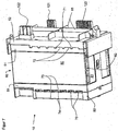
- FIG. 7 shows a perspective view of the feed module 10 in the assembled state.
- the housing 53 is closed by means of a cover 81, so as to prevent contact of the current-carrying fuse elements 30 from below.
- a cover 80 is arranged parallel to the plate 40 on the housing 53, which covers the in FIG. 5 and FIG. 6 covering shown fuse elements 30.
- a gap 82 is formed, which is the outflow of heated cooling air from the housing 53 allows.
- the lateral arrangement of the lid 80 on the second housing part 51 allows the secure cover of the fuse elements 30 in the energized state.
- the lid 80 is fired again. bar and open from the outside to exchange defective fuse elements 30 can.
- FIG. 8 shows a perspective view of a second feed module 1.
- the second feed module 1 has with respect to in the FIGS. 1 to 7 shown first feed module 10 in place of the terminal contacts formed as a contact slide 13, 14, 15, 111, 112 alternative terminal contacts 100, 101, 102, which serve to connect the second feed module 1 with circuit lines not shown.
- the connection contacts 100, 101, 102 comprise a plurality of connection openings 103, in each of which a counterpart of the connection contact 100, 101, 102 of the Anschiussleitüng engages and creates an electrically conductive connection to the respective contact of the connection contact 100, 101, 102.
- the second feed module 1 comprises a fan 90, which is arranged above the securing elements 30 in order to supply the securing elements 30 with sufficient cooling air.
- the fan 90 sucks in cooling air on the underside of the second feed module 1.
- the sucked cooling air is guided past the securing elements 30 and leaves as heated cooling air, as in FIG FIG. 1 to FIG. 7 shown, the housing 53 on the upper side through the first opening 92nd
- the second feed module 1 is designed to establish an electrical connection to the first feed module 10 by means of the contact bridges 16 of the first feed module 10. Furthermore, the connection contacts 120, 121, 122 provide a connection to the drive module 11 on the side facing the drive module 11.
- the fuse elements 30 of the second feed module 1 are as well as in FIG. 1 to FIG. 7 fuse elements 30 shown connected by bus bars 35, 36 and limit a current flow on the input side of the terminal contacts 100, 101, 102, which are arranged on the front side of the second feed module 1, to the rear side arranged terminal contacts 120, 121, 122 on the output side to the drive module 11th
- dargestellen fan 90 is arranged in a first feed module 10, if additional cooling of the components, in particular the fuse elements should be required.
Landscapes
- Engineering & Computer Science (AREA)
- Microelectronics & Electronic Packaging (AREA)
- Fuses (AREA)
- Cooling Or The Like Of Electrical Apparatus (AREA)
- Details Of Connecting Devices For Male And Female Coupling (AREA)
Description
- Die Erfindung betrifft ein Einspeisemodul zur Einspeisung von elektrischem Strom in ein Antriebsmodul, wobei das Einspeisemodul einen ersten Anschlussköntakt und einen zweiten Anschlusskontakt aufweist, wobei der erste Anschlusskontakt ausgelegt ist, das Einspeisemodul mit dem Antriebsmodul zu verbinden, und der zweite Anschlusskontakt ausgelegt ist, eine Verbindung zu einer Stromversorgung bereitzustellen.
- Es sind Antriebssysteme mit einem Antriebsmodul, einem Einspeisemodul und einer Verbindung zu einer Steuereinheit bekannt, wobei das Einspeisemodul mit dem Antriebsmodul und einer Stromversorgung verbunden ist. Das Antriebsmodul steuert dabei einen Motor an und stellt dieser die Stromversorgung bereit.
- Gemäß "UL Standard for Safety for Industrial Control Panels, UL 508A" ist es erforderlich, dass Antriebsmodule jeweils separat mit Sicherungselementen gegen ein Überschreiten eines vorgegebenen maximalen Stroms abgesichert sind. Üblicherweise werden die Sicherungselemente in dem Antriebsmodul angeordnet, wobei die Sicherungselemente an einen mit dem Antriebsmodul verbundenen Motor angepasst sind. Dies erfordert jedoch eine entsprechende konstruktive Anpassung des Antriebsmoduls an die Erfordernisse des UL-Standards, sowie an den am Antriebsmodul angeschlossenen Motor.
- Aus der
US 2008/268671 A1 ist ein Sicherungsverteilerkasten bekannt, über den Strom eingespeist werden kann, wobei zwei Leiterkarten vorgesehen sind, auf denen jeweils Anschlüsse angeordnet sind. Zwischen den Anschlüssen sind dann die Sicherungselemente geschaltet, die wiederum auf der einen Leiterplatte angeordnet sind, um den Stromfluss zwischen den Anschlusskontakten zu begrenzen. - Die
US 4 989 118 zeigt einen Stromunterbrecher, bei dem mehrere Stromunterbrecher über eine Schiene zusammen verbunden werden könnten. - Es ist daher Aufgabe der Erfindung, eine vereinfachte Abscherung eines Antriebsmoduls bereitzustellen.
- Diese Aufgabe wird durch ein Einspeisemodul gemäß Anspruch 1 gelöst. Weitergehende Ausführungsformen sind in den abhängigen Ansprüchen angegeben.
- Erfindungsgemäß wurde erkannt, dass ein verbessertes Einspeisemodul dadurch bereitgestellt werden kann, dass das Einspeisemodul einen ersten Anschlusskontakt und einen zweiten Anschlusskontakt aufweist, wobei der erste Anschlusskontakt das Einspeisemodul mit dem Antriebsmodul verbindet und der zweite Anschlusskontakt eine Verbindung zu einer Stromversorgung bereitstellt, wobei zwischen dem ersten Anschlusskontakt und dem zweiten Anschlusskontakt ein Sicherungselement angeordnet ist, das mit den beiden Anschlusskontakten verbunden ist und einen Stromfluss zwischen dem ersten Anschlusskontakt und dem zweiten Anschlusskontakt begrenzt.
- Auf diese Weise wird gewährleistet, dass ein Antriebsmodul ohne konstruktive Umbauten zuverlässig gegen eine Überstromung abgesichert ist. Ferner kann auf diese Weise das Antriebsmodul entsprechend verschiedener unterschiedlicher Standards modular durch das Sicherungselement abgesichert werden.
- In einer weiteren Ausführungsform der Erfindung ist der erste Anschlusskontakt auf einer ersten Leiterkarte und der zweite Anschlusskontakt auf einer zweiten Leiterkarte angeordnet, wobei zwischen der ersten Leiterkarte und der zweiten Leiterkarten das Sicherungselement angeordnet und mit den Leiterkarte verbunden ist. Auf diese Weise können die Sicherungselemente einfach in dem Einspeisemodul befestigt werden.
- In einer weiteren Ausführungsform der Erfindung weist der zweite Anschlusskontakt einen Kontaktschieber mit einem Kontaktschieber und einer Kontaktbrücke auf, die vom Kontaktschieber betätigt wird und in ein weiteres Einspeisemodul eingreift, um eine elektrische Verbindung zu dem weiteren Einspeisemodul bereitzustellen. Auf diese Weise kann einfach und schnell eine Verbindung von dem Einspeisemodul zu einem weiteren Einspeisemodul erstellt werden, was insbesondere bei der Zusammenstellung von einer Mehrzahl von Antriebsmodulen zu einem Mehrachsantriebssystem von Vorteil ist.
- In einer weiteren Ausführungsform der Erfindung ist das Sicherungselement mit einer Stromschiene verbunden, die mit einer der beiden Leiterkarten verbunden ist und eine elektrische Verbindung von dem Sicherungselement zu einer der beiden Leiterkarten bereitstellt. Mittels der Stromschiene können sicher hohe Ströme von der Leiterkarte zu dem Sicherungselement geleitet werden.
- In einer weiteren Ausführungsform der Erfindung ist die Stromschiene Z-förmig ausgebildet und verbindet eine Platte mit einer der beiden Leiterkarten. Auf diese Weise kann die räumliche Anordnung der Platte innerhalb eines Gehäuses des Einspeisemoduls einfach festgelegt werden.
- In einer weiteren Ausführungsform der Erfindung umfasst das Sicherungselement einen Sicherungskörper und einen Sicherungshalter, wobei der Sicherungshalter ah der Platte befestigt und mit der Stromschiene verbunden ist, und wobei der Sicherungshalter den Sicherungskörper im Gehäuse des Einspeisemoduls befestigt. Auf diese Weise wird eine vibrationsfeste Befestigung des Sicherungskörpers im Einspeisemodul bereitgestellt.
- In einer weiteren Ausführungsform der Erfindung ist die erste Leiterkarte mit der zweiten Leiterkarte mittels eines Verbindungsbolzens verbunden. Auf diese Weise können einfach die beiden Leiterkarten gegeneinander abgestützt werden sowie vom ersten Anschlusskontakt zum zweiten Anschlüsskontakt eine Verbindung ohne Sicherungselement bereitgestellt werden.
- In einer weiteren Ausführungsform der Erfindung weist das Gehäuse des Einspeisemoduls einen ersten, einen zweiten und einen dritten Gehäuseteil auf, wobei der erste Gehäuseteil sowohl mit dem zweiten als auch mit dem dritten Gehäuseteil verbindbar ist. Auf diese Weise ist gewährleistet, dass die drei Gehäuseteile zusammen ein erstes Gehäuse ausbilden können, wobei mittels des ersten Gehäuseteils und des dritten Gehäuseteils ein zweites Gehäuse ausbildbar ist, welches als Einspeisemodul ohne Sicherungselement ausgebildet ist.
- In einer weiteren Ausführungsform der Erfindung ist der zweite Gehäuseteil zwischen dem ersten und dem dritten Gehäuseteil angeordnet, wobei der erste Gehäuseteil einen ersten zinnenförmig ausgebildeten Bereich umfasst, der dem zweiten Gehäuseteil zugewandt ist. Der zweite Gehäuseteil umfasst einen zweiten zinnenförmige Bereich, der derart ausgebildet ist, dass der zweite zinnenförmige Bereich in den ersten zinnenförmigen Bereich eingreift. Auf diese Weise wird gewährleistet, dass Öffnungen, die mittels des ersten zinnenförmigen Bereichs des ersten Gehäuseteils und dem dritten Gehäuseteil ausgebildet werden, bei dem Einspeisemodul mit drei Gehäuseteilen zuverlässig verschlossen werden.
- In einer weiteren Ausführungsform der Erfindung weist das Gehäuse einen Deckel auf, der in einem Bereich des Sicherungselements seitlich am Gehäuse angeordnet ist, wobei der Deckel von außen zu öffnen und wieder verschließbar ist und das Sicherungselement abdeckt. Auf diese Weise wird gewährleistet, dass die stromführenden Sicherungen zuverlässig gegen externen Angriff von außen abgesichert sind, wobei durch die seitliche Anordnung des Deckels am Gehäuse der Monteur gezwungen ist, das Einspeisemodul vom Antriebsmodul zu trennen, um das Sicherungselement wechseln zu können. Dies gewährleistet zuverlässig, dass das Sicherungselement während des Wechsels stromfrei ist.
- In einer weiteren Ausführungsform der Erfindung ist in dem Einspeisemodul ein Lüfter angeordnet ist, der ausgelegt ist, Kühlluft durch das Einspeisemodul zu fördern. Auf diese Weise kann eine Betriebstemperatur der Sicherungselemente durch eine Zwangskühlung mittels des Lüfters sichergestellt werden.
- Nachfolgend wird die Erfindung anhand von Figuren näher erläutert. Dabei zeigen:
-
Figur 1 eine perspektivische Ansicht eines ersten Einspeisemoduls an einem Antriebsmodul im montierten Zustand; -
Figur 2 eine Vorderansicht des ersten Einspeisemoduls; -
Figur 3 eine Vorderansicht des ersten Einspeisemoduls mit einem demontierten ersten Gehäuseteil; -
Figur 4 eine Seitenansicht des ersten Einspeisemoduls; -
Figur 5 eine perspektivische Ansicht des ersten Einspeisemoduls; -
Figur 6 eine perspektivische Ansicht des ersten Einspeisemoduls in teilmontiertem Zustand; -
Figur 7 eine perspektivische Ansicht des ersten Einspeisemoduls 10; und -
Figur.8 eine perspektivische Ansicht eines zweiten Einspeisemoduls. -
Figur 1 zeigt eine perspektivische Ansicht eines ersten Einspeisemoduls 10 an einem Antriebsmodul 11 im montierten Zustand. Das Antriebsmodul 11 ist als Servoverstärker ausgebildet und dient zur Ansteuerung eines nicht dargestellten Servomotors. An einer Vorderseite des Antriebsmoduls 11 ist das Einspeisemodul 10 angeordnet. Das erste Einspeisemodul 10 umfasst ein Gehäuse 53, an dessen Vorderseite mehrere Kontaktschieber 13, 14, 15 angeordnet sind, die die Anschlusskontakte 110, 111, 112 des ersten Einspeisemoduls bilden. Die Kontaktschieber 13, 14, 15 umfassen Kontaktbrücken 16 , wobei die Kontaktschieber 13, 14, 15 nach links und rechts an der Vorderseite des ersten Einspeisemoduls 10 verschoben werden können. Ferner weisen die Kontaktschieber 13, 14, 15 mehrere Verschraubungsöffnungen 6 auf. Das Gehäuse 53 des ersten Einspeisemoduls 10 ist dreiteilig ausgebildet und umfasst ein erstes Gehäuseteil 50, an dem die Kontaktschieber 13, 14, 15 angeordnet sind, ein zweites Gehäuseteil 51 und ein drittes Gehäuseteil 52, wobei das zweite Gehäuseteil 51 zwischen dem. ersten Gehäuseteil 50 und dem dritten Gehäuseteil 52 angeordnet ist. - Im rechtsseitigen.Bereich des Gehäuses 53 im Übergangsbereich des ersten Gehäuseteils 50 zum zweiten Gehäuseteil 51 umfasst das Gehäuse 53 ferner mehrere Kontaktöffnungen 70, die zur Aufnahme der Kontaktbrücken 16 eines weiteren Einspeisemoduls ausgelegt sind. Rückseitig weist das Gehäuse 53 ein Rastelement 55 auf, das in eine Rastnase 58 des Antriebsmoduls 11 eingreift.
-
Figur 2 zeigt eine Vorderansicht des ersten Einspeisemoduls 10. Die Kontaktschieber 13, 14, 15 sind in einem ausgefahrenen, betätigten Zustand dargestellt, bei welchem die Kontaktbrücken 16 aus dem Gehäuse 53 des ersten Einspeisemoduls 10 ragen, um in ein weiteres Einspeisemodul einzugreifen und Kontaktelemente 19 eines weiteren Einspeisemoduls zu kontaktieren. Um das erste Einspeisemodul 10 an dem Antriebsmodul 11 zu montieren, werden die Kontaktschieber 13, 14, 15 nach rechts verschoben, so dass die Kontaktbrücken 16 im Gehäuse 53 des ersten Einspeisemoduls 10 eingeschoben sind. Wird das Einspeisemodul 10 in einem Verbund mit mehreren Antriebsmodulen und weiteren Einspeisemodulen montiert, so wird das Einspeisemodul 10 auf das Antriebsmodul 11 aufgesteckt, wobei die Rastelemente 55 in Rastnasen 58 des Antriebsmoduls 11 eingreifen und das erste Einspeisemodul 10 reversibel am Antriebsmodul 11 befestigt. Um einen zuverlässigen Kontakt zu den weiteren Einspeisemodulen zu gewährleisten, werden die Kontaktschieber 13, 14 , 15 nach einer Verrastung des ersten Einspeisemoduls 10 am Antriebsmodul 11 nach links verschoben, so dass die Kontaktbrücken 16 in ein weiteres Einspeisemodul hinein ragen und dort in nicht dargestellte Kontaktelemente eingreifen. -
Figur 3 zeigt die inFigur 2 dargestellte Vorderansicht des ersten Einspeisemoduls 10 ohne das erste Gehäuseteil 50, welches die Kontaktschieber 13,14,15 trägt. Auf einer ersten Leiterkarte 20, die parallel zur Zeichenebene angeordnet ist, sind mehrere Schraubenaufnahmen 18 mit Befestigungsschrauben 17 angeordnet. Die Kontaktbrücken 16, von denen.hier nur ein Teil dargestellt sind, umfassen jeweils ein Langloch 22, das in Richtung der Längsachse der Kontaktbrücken 16 angeordnet ist. Zur Befestigung der Kontaktbrücken 16 durchgreifen die Befestigungsschrauben 17 die Langlöcher 22 der Kontaktbrücken 16 und befestigen diese an der ersten Leiterkarte 20. Die Kontaktbrücken 16 können durch die Kontaktschieber 13, 14, 15 verschoben werden, wobei in dem Langloch 22 die Befestigungsschraube 17 zum Verschieben gelöst ist. Um ein vibrationsfestes Kontaktieren über die Kontaktschieber 13, 14, 15 zu gewährleisten, wird durch die Verschraubungsöffnungen 6 die Befestigungsschraube 17 angezogen, so dass die Kontaktbrücke 16 zuverlässig befestigt ist. Dies erlaubt eine schnelle Montage und Demontage des ersten Einspeisemoduls 10. - Die erste Leiterkarte 20 weist ferner Befestigungspunkte 23 auf, die zur Verbindung der ersten Leiterkarte 20 mit einer dahinter angeordneten zweiten Leiterkarte 21 dienen. Rechtsseitig sind an der ersten Leiterkarte 20 mehrere Kontaktelemente 19 angeordnet, in die die Kontaktbrücke 16 eines weiteren Einspeisemoduls eingreifen können, um so eine Verbindung zu dem weiteren Einspeisemodul bereitzustellen.
-
Figur 4 zeigt eine Seitenansicht des ersten Einspeisemoduls 10 in teilmontiertem Zustand. Im Gehäuse 53 des ersten Einspeisemoduls 10 sind gegenüber liegend am ersten Gehäuseteil 50 die erste Leiterkarte 20 und am dritten Gehäuseteil 52 parallel zur ersten Leiterkarte 20 eine zweite Leiterkarte 21 angeordnet. Dabei wird in derFigur 4 die zweite Leiterkarte 21 durch das dritte Gehäuseteil 52 verdeckt. Die Leiterkarten 20, 21 sind parallel zur Vorder- und Rückseite des Gehäuses 53 angeordnet und im Gehäuse 53 mittels Befestigungselementen 38 befestigt. Senkrecht zu den beiden Leiterkarten 20, 21 ist eine Platte 40 angeordnet, die elektrisch isolierendes Material aufweist und zur Befestigung der Stromschienen 35, 36 sowie der auf der gegenüberliegenden Seite der Platte 40 angeordneten und inFigur 5 dargestellten Sicherungselemente 30 dient. - Eine an der ersten Leiterkarte 20 angeordnete erste Stromschiene 35 ist Z-förmig ausgebildet und ist an einem Ende mit einem Winkelelement 39 mittels einer Verbindungsschraube 24 befestigt. Am anderen Ende weist die erste Stromschiene 35 eine Aufnahme 37 auf. Die Z-förmige Ausbildung der ersten Stromschiene 35 dient dazu, einen Sicherheitsabstand d zwischen den Stromschienen 35, 36 und den Sicherungselementen 30 festzulegen. Auf diese Weise wird gewährleistet, dass der für Luft notwendige Sicherheitsabstand d korrespondierend zu einer am Sicherungselement 30 anliegenden Spannung und zur Isolation des Sicherungselements 30 eingehalten wird. Durch die Z-förmige Ausbildung kann dabei die Aufnahme 37 zur Befestigung des Sicherungselements 30 in der Höhe (x-Richtung) konstruktiv an der Platte 40 festgelegt werden, so dass der vorhandene Bauraum im Gehäuse 53 optimal ausgenutzt wird. Ferner wird durch die Z-förmige Ausbildung der ersten Stromschiene 35 die Bauraumtiefe in z-Richtung des Gehäuses 53 optimal ausgenutzt, um eine schmale Ausführung des Einspeisemoduls 10 zu gewährleisten.
- Eine zweite Stromschiene 36 ist plattenförmig ausgebildet und verbindet eine Ausgangsseite der Sicherungselemente 30 und die Aufnahme 37 mit der zweiten Leiterkarte 21. Die zweiten Stromschienen 36 sind an der zweiten Leiterkarte 21 mittels der Verbindungsschrauben 24 und nicht dargestellten Winkelelemente befestigt. Auf der Rückseite der Platte 40 sind, wie in
Figur 5 und6 gezeigt, die Sicherungselemente 30 angeordnet. Die Aufnahme 37 ist mit dem Sicherungselement 30 durch die Platte 40 elektrisch leitend verbunden. An der zweiten Leiterkarte 21 sind Anschlusskontakte 120, 121, 122 vorgesehen, um das erste Einspeisemodul 10 im montierten Zustand mit dem Antriebsmodul 11, wie inFigur 1 gezeigt, zu verbinden. Dabei stellt ein erster Anschlusskontakt 120 die über den ersten Kontaktschieber 13 abgegriffene Netzspannung zur Verfügung. Ein zweiter Anschlusskontakt 121 dient einem Zwischenkreisverbund zum Energieaustausch zwischen den einzelnen Antriebsmodulen 11. Eine Verbindung für den zweiten Anschlusskontakt 121 wird über den dritten Kontaktschieber 15 zu weiteren Einspeisemodulen bereitgestellt. Ein dritter Anschlusskontakt 122 ist mittels Verbindungsbolzen 45 mit dem zweiten Kontaktschieber 14 verbünden und stellt eine Hilfsspannung in Form von Gleichspannung zur Versorgung des Antriebsmoduls 11 oder zur Steuerung, z.B. einer Bremse, eines Thermokontakts und/oder.für digitale Ein- und Ausgänge, bereit. Aufgrund der niedrigen darin verlaufenden Steuerströme, ist eine Absicherung gemäß dem UL-Standard nicht vorgesehen. Ferner ist der dritte Anschlusskontakt 122 und der zweiten Kontaktschieber 14 durch den Verbindungsbolzen 45 widerstandsarm verbunden. -
Figur 5 zeigt eine perspektivische Ansicht des ersten Einspeisemoduls 10. Dabei ist eine Rückseite derFigur 4 dargestellt. Auf der Platte 40 sind die Sicherungselemente 30 angeordnet. Die Sicherungselemente 30 weisen je nach abzusichernder Stromhöhe eine unterschiedliche Größe auf. So sind die ersten unterhalb angeordneten Sicherungskörper 32 zur Absicherung des ersten Anschlusskontakts 120 kleiner ausgebildet als die oberhalb der ersten Sicherungskörper angeordneten zweiten Sicherungskörper 3i zur Absicherung des Zwischenkreisverbundes. Entsprechend der Größe der Sicherungskörper 31, 32 sind die korrespondierenden Sicherungshalter 33, 34 ausgebildet und an der Platte 40 befestigt. - Die Sicherungshalter 33, 34 sind in x-Richtung derart auf der Platte 40 voneinander beabstandet, dass ein Üerschlagen von Spannungen zu den daneben angeordneten Sicherungshalter 33, 34 vermieden wird und ein für die anliegenden Spannungen notwendiger Sicherheitsabstand d eingehalten wird. Die Sicherungshalter 33, 34 greifen rückseitig in die Aufnahme 37 ein und sind dadurch mit den Stromschienen 35, 36 verbunden. Anstelle der dargestellten Schmelzsicherungen sind auch elektronische Sicherungen, selbstrückstellende Sicherungen, Motorschutzschalter oder Leistungsschutzschalter denkbar.
- Die Verbindungsbolzen 45 sind mittels Verbindungsschrauben 24 an der ersten Leiterkarte 20 befestigt. An dem zur Verbindungsschraube 24 gegenüber liegenden Ende des Verbindungsbolzen 45 weist der Verbindungsbolzen 45 ein Gewinde auf, das in montiertem Zustand in eine Bolzenverschraubung 46, die innenseitig an der zweiten Leiterkarte 21 angeordnet ist, eingreift. Auf diese Weise kann bei der Montage der Verbindungsbolzen 45 einfach montiert werden, wobei ferner eine zuverlässige Stromübertragung von der ersten Leiterkarte 20 zur zweiten Leiterkarte 21 gewährleistet ist. Die oben und unten im Gehäuse angeordneten Verbindungsbolzen 45 stützen ferner die beiden Leiterkarten 20, 21 gegeneinander ab und befestigen diese zuverlässig im Gehäuse 53. Ferner ist die Platte 40 zur besseren Abstützung der Leiterkarten 20, 21 mit den Leiterkarten 20, 21 verbunden.
- Die erste Stromschiene 35 ist ferner zusätzlich zur Z-förmigen Ausbildung S-förmig ausgebildet, um die Anordnung der Sicherungshalter 33, 34 auf der Platte 40 in y-Richtung bauraumtechnisch günstig anzuordnen. Dabei kann je nach Ausbildung der S-Form der Stromschiene 35 die Position der Platte in y-Richtung konstruktiv angepasst werden.
-
Figur 6 zeigt eine perspektivische Ansicht des Einspeisemoduls 10 in teilmontiertem Zustand. Die Anordnung der Leiterkarten 20, 21 entspricht der inFigur 5 gezeigten Ausführungsform des ersten Einspeisemoduls 10. Dabei ist das Gehäuse 53 des Einspeisemoduls 10 im Bereich der Sicherungselemente 30 geöffnet. Der dritte Gehäuseteil 52 umfasst einen ersten zinnenförmigen Bereich 72, der dem zweiten Gehäuseteil 51 zugewandt ist. Der zweite Gehäuseteil 51, der zwischen dem ersten Gehäuseteil 50 und dem dritten Gehäuseteil 52 angeordnet ist, weist einen zweiten zinnenförmigen Bereich 71 auf, der dem ersten zinnenförmigen Bereich 72 des dritten Gehäuseteils 52 zugewandt ist. Der zweite zinnenförmige Bereich 71 ist derart ausgebildet, dass der zweite zinnenförmige Bereich 71 in die Lücken des ersten zinnenförmigen Bereichs 72 eingreift und dieser die Struktur des ersten zinnenförmigen Bereichs 72 so abdeckt, dass das Gehäuse 53 in diesem Bereich gegenüber der Umwelt abgeschlossen ist. - Zwischen dem ersten Gehäuseteil 50 und dem zweiten Gehäuseteil 51 sind die. Kontaktöffnungen 70 angeordnet, in die die Kontaktbrücken 16 eines weiteren Einspeisemoduls in montiertem Zustand durchgeführt sein können. Die Kontaktöffnungen 70 werden durch einen dritten zinnenförmigen Bereich 73, der am zweiten Gehäuseteil 51 angeordnet ist und dem ersten Gehäuseteil 50 zugewandt ist, sowie durch einen vierten zinnenförmigen Bereich 74 des ersten Gehäuseteils 50, der dem zweiten Gehäuseteil 51 zugewandt ist, gebildet. Durch die Ausbildung der Gehäuseteile 50, 51, 52 mit den zinnenförmigen Bereichen 71, 72, 73, 74 können die Gehäuseteile 50, 51, 52 zur Ausbildung eines Einspeisemoduls 10 mit Sicherungselementen 30 verwendet werden. Die Ausbildung mit den zinnenförmigen Bereichen 71, 74 ermöglicht aber auch, dass das erste Gehäuseteil 50 an dem dritten Gehäuseteil 52 anordbar ist. In diesem Fall nehmen die Gehäuseteile 50, 52 jedoch keine Sicherungselemente 30 auf und bilden ein weiteres Einspeisemodul mit den Kontaktschiebern 13, 14, 15, das eine Stromversorgung des Antriebsmoduls 11 ohne Absicherung vorsieht. Dabei bilden der erste zinnenförmige Bereich 71 und der vierte zinnenförmige Bereich 74 die Kontaktöffnungen 70 aus.
- Oberhalb der Sicherungselemente 30 ist ein Lüftungsgitter 60 am zweiten Gehäuse 51 angeordnet, das einen Zugriff von oben durch eine erste Öffnung 92 auf die Sicherungselemente 30 verhindert und ferner die Durchströmung von Kühlluft durch das Gehäuse 53 ermöglicht. Die Kühlluft tritt dabei durch eine zweite Öffnung 91 in das Gehäuse 53 ein.und verlässt das Gehäuse 53 oberseitig beim Lüftungsgitter 60. Auf diese Weise kann eine Kühlung der Sicherungselemente 30 durch natürliche Konvektion gewährleistet werden. Alternativ wäre auch denkbar das Lüftungsgitter 60 an einem in
Figur 7 gezeigten Deckel 80 innenseitig anzuordnen.
Das dritte Gehäuseteil 52 umfasst ferner seitlich angeordnete Rastelemente 55 mit einer Rastnocke 56 und einem Rastarm 57. Die Rastnocke 56 ist etwa in Richtung des Antriebsmoduls 11 ausgerichtet und umgreift dort in eine inFigur 1 dargestellte Rastnase 58. Die Rastnocke 56 kann durch den Rastarm 57 gelöst werden, um das Gehäuse 53 des Einspeisemoduls 10 vom Antriebsmodul 11 abziehen zu können. Auf diese Weise kann das Gehäuse 53, aber auch ein Einspeisemodul bestehend nur aus dem ersten und dritten Gehäuseteil 50, 52, reversibel am Antriebsmodul 11 befestigt werden. - Die dem Antriebsmodul 11 zugewandte Seite des dritten Gehäuseteils 52 umfasst mehrere Versteifungsrippen 95, die eine Verbindungssteifigkeit des dritten Gehäuseteils 52 gewährleisten, und so ein verbindungssteifes Einspeisemodul 10 sicherstellen.
-
Figur 7 zeigt eine perspektivische Ansicht des Einspeisemoduls 10 in montiertem Zustand. Unterhalb der inFigur 6 dargestellten Sicherungselemente 30 ist das Gehäuse 53 mittels einer Abdeckung 81 verschlossen, um so ein Berühren der stromführenden Sicherungselemente 30 von unten zu verhindern. Seitlich ist parallel zur Platte 40 am Gehäuse 53 ein Deckel 80 angeordnet, der die inFigur 5 undFigur 6 gezeigten Sicherungselemente 30 abdeckt. Zwischen der Abdeckung 81 und dem Deckel 80 ist ein Spalt 82 ausgebildet, der das Ausströmen von erwärmter Kühlluft aus dem Gehäuse 53 ermöglicht. Die seitliche Anordnung des Deckels 80 am zweiten Gehäuseteil 51 ermöglicht die sichere Abdeckung der Sicherungselemente 30 im stromführenden Zustand. Der Deckel 80 ist wieder verschieß. bar und von außen zu öffnen um defekte Sicherungselemente 30 tauschen zu können. Sollten mehrere Einspeisemodule 10 nebeneinander an verschiedenen Antriebsmodulen 11 montiert sein, so können defekte Sicherungselemente 30 nur dann gewechselt werden, wenn das Einspeisemodul 10 von weiteren Einspeisemodulen getrennt und vom Antriebsmodul 11 abgezogen wird. Auf diese Weise wird ein Zugriff auf die Sicherungselemente 30 ermöglicht, wobei die Sicherungselemente 30 durch das Abziehen des Einspeisemoduls 10 vom Antriebsmodul 11 und weiteren Einspeisemodulen 10 stromlos sind. -
Figur 8 zeigt eine perspektivische Darstellung eines zweiten Einspeisemoduls 1. Das zweite Einspeisemodul 1 weist gegenüber dem in denFiguren 1 bis 7 gezeigten ersten Einspeisemodul 10 anstelle der als Kontaktschieber 13, 14, 15 ausgebildeten Anschlusskontakte 110, 111, 112 alternative Anschlusskontakte 100, 101, 102 auf, die dazu dienen, das zweite Einspeisemodul 1 mit nicht dargestellten An schlussleitungen zu verbinden. Die Anschlusskontakte 100, 101, 102 umfassen mehrere Anschlussöffnungen 103, in die jeweils ein Gegenstück des Anschlusskontakts 100, 101, 102 der Anschiussleitüng eingreift und eine elektrisch leitende Verbindung zu dem jeweiligen Kontakt des Anschlusskontakts 100, 101, 102 erstellt. - Ferner umfasst das zweite Einspeisemodul 1 einen Lüfter 90, der oberhalb der Sicherungselemente 30 angeordnet ist, um die Sicherungselemente 30 mit ausreichend Kühlluft zu versorgen. Dazu saugt der Lüfter 90 Kühlluft unterseitig des zweiten Einspeisemoduls 1 an. Die angesaugte Kühlluft wird an den Sicherungselementen 30 vorbeigeführt und verlässt als erwärmte Kühlluft, wie in
Figur 1 bis Figur 7 gezeigt, das Gehäuse 53 oberseitig durch die erste Öffnung 92. - Das zweite Einspeisemodul 1 ist ausgelegt, mittels der Kontaktbrücken 16 des ersten Einspeisemoduls 10 eine elektrische Verbindung zu dem ersten Einspeisemodul 10 aufzubauen. Ferner stellen die Anschlusskontakte 120, 121, 122 an der dem Antriebsmodul 11 zugewandten Seite eine Verbindung zu dem Antriebsmodul 11 bereit. Die Sicherungselemente 30 des zweiten Einspeisemoduls 1 sind ebenso wie die in
Figur 1 bis Figur 7 gezeigten Sicherungselemente 30 mittels Stromschienen 35, 36 verbunden und begrenzen einen Stromfluss eingangsseitig von den Anschlusskontakten 100, 101, 102, die an der Vorderseite des zweiten Einspeisemoduls 1 angeordnet sind, zu den rückseitig angeordneten Anschlusskontakten 120, 121, 122 ausgangsseitig zu dem Antriebsmodul 11. - Selbstverständlich ist es auch möglich, den in
Figur 8 dargestellen Lüfter 90 in einem ersten Einspeisemodul 10 anzuordnen, sofern eine zusätzliche Kühlung der Bauelemente, insbesondere der Sicherungselemente erforderlich sein sollte.
Claims (10)
- Einspeisemodul (10) zum Einspeisen von elektrischem Strom in ein Antriebsmodul (11),
mit einem Gehäuse (53) mit einer Vorderseite und einer Rückseite,
mit einem an der Rückseite angeordneten ersten Anschlusskontakt und einem an der Vorderseite angeordneten zweiten Anschlusskontakt, wobei der erste Anschlusskontakt (120, 121, 122) auf einer ersten Leiterkarte (20) angeordnet ist und ausgelegt ist, das Einspeisemodul (10) mit dem Antriebsmodul (11) zu verbinden, und der zweite Anschlusskontakt (110, 111, 112) auf einer zweiten Leiterkarte (21) angeordnet ist und ausgelegt ist, eine Verbindung zu einer Stromversorgung bereitzustellen, und
mit zumindest einem Sicherungselement (30), das im Gehäuse (53)zwischen dem ersten Anschlusskontakt und dem zweiten Anschlusskontakt angeordnet ist und mit dem ersten Anschlusskontakt (120, 121, 122) und dem zweiten Anschlusskontakt (110, 111, 112; 100, 101, 102) verbunden und ausgelegt ist, einen Stromfluss zwischen dem ersten Anschlusskontakt (120, 121, 122) und dem zweiten Anschlusskontakt (110, 111, 112) zu begrenzen,
dadurch gekennzeichnet,
dass das Sicherungselement (30) zwischen der ersten Leiterkarte (20) und der zweiten Leiterkarte (21) angeordnet ist,
dass der zweite Anschlusskontakt (110, 111, 112) einen Kontaktschieber (13, 14, 15) eine Kontaktbrücke (16) umfasst, wobei der Kontaktschieber (13, 14, 15) ausgelegt ist, um die Kontaktbrücke (16) seitlich aus dem Gehäuse (53) herauszuschieben, um mit der Kontaktbrücke (16) seitlich in ein Gehäuse eines weiteren Einspeisemoduls einzugreifen und ein Kontaktelement des weiteren Einspeisemoduls zu kontaktieren, und
dass das Gehäuse (53) einen Deckel (80) umfasst, der in einem Bereich des Sicherungselements (30) seitlich am Gehäuse (53) angeordnet ist, wobei der Deckel (80) von außen zu öffnen und wieder verschließbar ist und das Sicherungselement (30) abdeckt. - Einspeisemodul (10) nach Anspruch 1, dadurch gekennzeichnet, dass das Sicherungselement (30) mit einer Stromschiene (35, 36) verbunden ist, die mit einer der beiden Leiterkarten (20, 21) verbunden ist und eine elektrische Verbindung zu einer der beiden Leiterkarten (20, 21) bereitstellt.
- Einspeisemodul (10) nach Anspruch 2, dadurch gekennzeichnet, dass die Stromschiene (35) Z-förmig ausgebildet und ausgelegt ist, eine Platte (40) mit einer der beiden Leiterkarten (20, 21) zu verbinden.
- Einspeisemodul (10) nach Anspruch 3, dadurch gekennzeichnet, dass das Sicherungselement (30) einen Sicherungskörper (31, 32) und einen Sicherungshalter (33, 34) umfasst, wobei der Sicherungshalter (33, 34) an der Platte (40) befestigt und mit der Stromschiene (35, 36) verbunden ist und der Sicherungshalter (33, 34) den Sicherungskörper (31, 32) im Gehäuse (53) des Einspeisemoduls (1; 10) befestigt.
- Einspeisemodul (10) nach einem der Ansprüche 1 bis 4, dadurch gekennzeichnet, dass die erste Leiterkarte (20) mit der zweiten Leiterkarte (21) mittels eines Verbindungsbolzens (45) verbunden ist.
- Einspeisemodul (10) nach einem der Ansprüche 1 bis 5, dadurch gekennzeichnet, dass das Gehäuse (53) einen ersten, einen zweiten und einen dritten Gehäuseteil (50, 51, 52) umfasst, wobei der erste Gehäuseteil (50) sowohl mit dem zweiten Gehäuseteil (51) als auch mit dem dritten Gehäuseteil (52) verbindbar ist.
- Einspeisemodul (10) nach Anspruch 6, dadurch gekennzeichnet, dass das zweite Gehäuseteil (51) zwischen dem ersten und dem dritten Gehäuseteil (50, 52) angeordnet ist, wobei der erste Gehäuseteil (50) einen ersten zinnenförmig ausgebildeten Bereich (72) umfasst, der dem zweiten Gehäuseteil (51) zugewandt ist, und der zweite Gehäuseteil (51) einen zweiten zinnenförmigen Bereich (71) umfasst, der derart ausgebildet ist, dass der zweite zinnenförmige Bereich (71) in den ersten zinnenförmigen Bereich (72) eingreift.
- Einspeisemodul (10) nach einem der Ansprüche 1 bis 7, dadurch gekennzeichnet, dass das Gehäuse (53) eine erste Öffnung (92) und eine zweite Öffnung (91) aufweist, wobei die erste Öffnung (92) an einer Oberseite (5) des Gehäuses (53) und die zweite Öffnung (91) an einer Unterseite des Gehäuses (53) angeordnet ist, wobei die Öffnungen (91, 92) ausgelegt sind, einen Kühlluftstrom durch das Gehäuse (53) zu führen.
- Einspeisemodul (10) nach einem der Ansprüche 1 bis 8, dadurch gekennzeichnet, dass in dem Einspeisemodul (1; 10) ein Lüfter (90) angeordnet ist, der ausgelegt ist, Kühlluft durch das Einspeisemodul (1; 10) zu fördern.
- Einspeisemodul (10) nach einem der Ansprüche 1 bis 9, dadurch gekennzeichnet, dass das Sicherungselement (30) als Schmelzsicherung oder elektronische Sicherung oder selbstrückstellende Sicherung oder Leistungsschutzschalter oder Motorschutzschalter ausgebildet ist.
Applications Claiming Priority (2)
| Application Number | Priority Date | Filing Date | Title |
|---|---|---|---|
| DE102010027901A DE102010027901A1 (de) | 2010-04-19 | 2010-04-19 | Einspeisemodul |
| PCT/EP2011/055767 WO2011131527A1 (de) | 2010-04-19 | 2011-04-13 | Einspeisemodul |
Publications (2)
| Publication Number | Publication Date |
|---|---|
| EP2561531A1 EP2561531A1 (de) | 2013-02-27 |
| EP2561531B1 true EP2561531B1 (de) | 2016-06-08 |
Family
ID=44246305
Family Applications (1)
| Application Number | Title | Priority Date | Filing Date |
|---|---|---|---|
| EP11714042.6A Active EP2561531B1 (de) | 2010-04-19 | 2011-04-13 | Einspeisemodul |
Country Status (4)
| Country | Link |
|---|---|
| US (1) | US8758061B2 (de) |
| EP (1) | EP2561531B1 (de) |
| DE (1) | DE102010027901A1 (de) |
| WO (1) | WO2011131527A1 (de) |
Cited By (1)
| Publication number | Priority date | Publication date | Assignee | Title |
|---|---|---|---|---|
| WO2025119541A1 (de) * | 2023-12-08 | 2025-06-12 | Ellenberger & Poensgen Gmbh | Schutzschaltermodul |
Families Citing this family (17)
| Publication number | Priority date | Publication date | Assignee | Title |
|---|---|---|---|---|
| DE102010041270B4 (de) | 2010-09-23 | 2022-12-08 | Siemens Aktiengesellschaft | Kompaktabzweig mit sicherungsbehaftetem Kurzschlusschutz |
| JP5660406B2 (ja) * | 2013-04-15 | 2015-01-28 | 株式会社安川電機 | モータ駆動装置及びモータ駆動システム |
| TWI518847B (zh) * | 2013-08-23 | 2016-01-21 | 森富科技股份有限公司 | Sequential series of multi - chip memory structure |
| DE102013111857B4 (de) * | 2013-10-28 | 2015-05-13 | Klaus Bruchmann Gmbh | Gesicherter Sammelschienenadapter |
| WO2015134390A1 (en) * | 2014-03-04 | 2015-09-11 | University Of Florida Research Foundation | Medication adherence monitoring device |
| JP6327554B2 (ja) * | 2014-04-16 | 2018-05-23 | パナソニックIpマネジメント株式会社 | 端子装置及び分電盤 |
| USD766840S1 (en) * | 2014-08-04 | 2016-09-20 | Beckhoff Automation Gmbh | Housing for electronic circuitry |
| USD758323S1 (en) * | 2014-08-04 | 2016-06-07 | Beckhoff Automation Gmbh | Housing for electronic circuitry |
| USD760175S1 (en) * | 2014-08-04 | 2016-06-28 | Beckhoff Automation Gmbh | Housing for electronic circuitry |
| USD760176S1 (en) * | 2014-08-04 | 2016-06-28 | Beckhoff Automation Gmbh | Housing for electronic circuitry |
| USD780127S1 (en) * | 2014-08-04 | 2017-02-28 | Beckhoff Automation Gmbh | Housing for electronic circuitry |
| DE102015104290A1 (de) | 2015-03-23 | 2016-09-29 | Phoenix Contact Gmbh & Co. Kg | Modulares Bussystem |
| FR3043851B1 (fr) * | 2015-11-13 | 2018-01-05 | Valeo Siemens Eautomotive France Sas | Barre de connexion electrique |
| CN106710996B (zh) * | 2016-12-07 | 2019-03-01 | 宁波爱维斯工贸有限公司 | 扩展式多用途保险座 |
| BE1027224B1 (de) | 2019-04-24 | 2020-11-23 | Phoenix Contact Gmbh & Co | Modularer Switch zum Einsatz in einem Datenübertragungs- und Steuerungssystem |
| DE102019127195A1 (de) | 2019-10-09 | 2021-04-15 | Phoenix Contact Gmbh & Co. Kg | Modulares Interfacesystem zum Anschließen einer Steuerungseinrichtung und von Feldgeräte |
| DE102021106522A1 (de) | 2020-03-27 | 2021-09-30 | Phoenix Contact Gmbh & Co. Kg | Backplanemodul zum elektrischen Verbinden mehrerer Funktionsmodule und modular aufgebautes Kommunikationssystem |
Family Cites Families (14)
| Publication number | Priority date | Publication date | Assignee | Title |
|---|---|---|---|---|
| DE6750051U (de) * | 1968-06-22 | 1969-01-02 | Elektro Bauelemente G M B H | Sicherungsunterteil oder stromkreisleiste fuer verteileranlagen |
| DE3423924A1 (de) * | 1984-06-29 | 1986-01-09 | Wolf-Dieter Dr.-Ing. 4600 Dortmund Oels | Vorrichtung zur aufnahme von mehreren schutzbauelementen |
| US4989118A (en) | 1989-04-21 | 1991-01-29 | Carlingswitch, Inc. | Off-set terminal configuration for electrically coupling the load side of adjacent circuit breakers |
| US5148139A (en) * | 1991-06-28 | 1992-09-15 | Square D Company | Fuse switch unit for panelboards |
| US5579217A (en) * | 1991-07-10 | 1996-11-26 | Kenetech Windpower, Inc. | Laminated bus assembly and coupling apparatus for a high power electrical switching converter |
| DE29719226U1 (de) * | 1997-10-29 | 1999-03-04 | Robert Bosch Gmbh, 70469 Stuttgart | Sammelschiene zur Verbindung zweier elektrischer Module |
| US6220876B1 (en) * | 1998-09-29 | 2001-04-24 | Delphi Technologies, Inc. | Electrical interconnect system and method for integrating a bussed electrical distribution center with a printed circuit board |
| DE10040651B4 (de) * | 2000-08-19 | 2004-02-05 | Erni Elektroapparate Gmbh | Elektronisches Gerät mit Daten- und/oder Energiebusverbindung |
| DK1387443T3 (da) * | 2002-08-01 | 2009-10-19 | Sew Eurodrive Gmbh & Co | Omformersystem |
| US6743027B1 (en) * | 2003-03-18 | 2004-06-01 | Lear Corporation | Remote zone connector and system |
| US7982331B2 (en) * | 2006-12-29 | 2011-07-19 | Cummins Power Generation Ip, Inc. | Transfer switch assembly |
| DE102006058328B3 (de) * | 2006-12-11 | 2008-05-08 | Siemens Ag | Mehrphasiges Strangsicherungs-Modul |
| US7983024B2 (en) | 2007-04-24 | 2011-07-19 | Littelfuse, Inc. | Fuse card system for automotive circuit protection |
| DE202010004061U1 (de) * | 2010-03-23 | 2010-06-24 | Theben Ag | Elektrisch koppelbares Installationsgerät |
-
2010
- 2010-04-19 DE DE102010027901A patent/DE102010027901A1/de not_active Withdrawn
-
2011
- 2011-04-13 WO PCT/EP2011/055767 patent/WO2011131527A1/de not_active Ceased
- 2011-04-13 EP EP11714042.6A patent/EP2561531B1/de active Active
-
2012
- 2012-10-17 US US13/654,127 patent/US8758061B2/en active Active
Non-Patent Citations (1)
| Title |
|---|
| None * |
Cited By (1)
| Publication number | Priority date | Publication date | Assignee | Title |
|---|---|---|---|---|
| WO2025119541A1 (de) * | 2023-12-08 | 2025-06-12 | Ellenberger & Poensgen Gmbh | Schutzschaltermodul |
Also Published As
| Publication number | Publication date |
|---|---|
| DE102010027901A1 (de) | 2011-10-20 |
| WO2011131527A1 (de) | 2011-10-27 |
| EP2561531A1 (de) | 2013-02-27 |
| US20130040494A1 (en) | 2013-02-14 |
| US8758061B2 (en) | 2014-06-24 |
Similar Documents
| Publication | Publication Date | Title |
|---|---|---|
| WO2011131527A1 (de) | Einspeisemodul | |
| EP2461440B1 (de) | Stecksystem | |
| EP3884742B1 (de) | Basismodul und funktionsmodul für ein schaltschranksystem | |
| DE102009023607B4 (de) | Verteiler für elektrische Leistung mit Stromsensor | |
| EP3884741B1 (de) | Schaltschranksystem aus basismodul und funktionsmodulen sowie funktionsmodul | |
| DE102012214366B4 (de) | Schaltvorrichtung für einen Stromschienen-basierten Fahrzeugstromverteiler | |
| DE102012219783A1 (de) | Batteriemodul mit vielfältigen Montagevarianten und Querung | |
| DE112016004427B4 (de) | Schaltungsanordnung und elektrischer verteiler | |
| EP2089945B1 (de) | Mehrphasiges strangsicherungs-modul | |
| DE10232650A1 (de) | Elektrischer Verbindungskasten und Verfahren zur Herstellung desselben | |
| DE102010060069B4 (de) | Elektrisches Verteilergehäuse | |
| DE102007019805B4 (de) | Kabelkasten | |
| EP2497169B1 (de) | Montageanordnung für elektrische geräte | |
| EP1830376B1 (de) | Vorrichtung zur Stromverteilung | |
| DE102016200288A1 (de) | Elektrische Komponenteneinheit, Schmelzsicherungseinheit und Fixierungsaufbau | |
| DE102005014465A1 (de) | Elektrisches Verbindergehäuse | |
| DE102012219781A1 (de) | Stromschiene zur elektrischen Verbindung von Batterieanschlüssen aneinandergereihter Batteriezellen | |
| EP3876355B1 (de) | Anschlussvorrichtung und elektromechanische baugruppe | |
| DE102019101859A1 (de) | Kontakt- und Busschienenanordnung, Elektronikgehäuseanordnung mit einer solchen Kontakt- und Busschienenanordnung, und Verfahren zur Entnahme eines Elektronikgehäuses aus einer solchen Elektronikgehäuseanordnung | |
| EP1353350B1 (de) | Hilfsschalter | |
| EP1787358B1 (de) | Strom-einspeisemodul mit käfig-zugfederklemmen | |
| DE102019103531B4 (de) | Überspannungsableiteranordnung mit in einem gemeinsamen Gehäuse befindlichen, vorkonfektionierten und elektrisch verschalteten Überspannungsableitern | |
| DE10340212B4 (de) | Verteileranordnung | |
| DE102020212249B4 (de) | Schaltschrank mit einem Kabelverlegekasten | |
| DE102004058712B4 (de) | Elektrischer Verteilerkasten |
Legal Events
| Date | Code | Title | Description |
|---|---|---|---|
| PUAI | Public reference made under article 153(3) epc to a published international application that has entered the european phase |
Free format text: ORIGINAL CODE: 0009012 |
|
| 17P | Request for examination filed |
Effective date: 20121005 |
|
| AK | Designated contracting states |
Kind code of ref document: A1 Designated state(s): AL AT BE BG CH CY CZ DE DK EE ES FI FR GB GR HR HU IE IS IT LI LT LU LV MC MK MT NL NO PL PT RO RS SE SI SK SM TR |
|
| DAX | Request for extension of the european patent (deleted) | ||
| GRAP | Despatch of communication of intention to grant a patent |
Free format text: ORIGINAL CODE: EPIDOSNIGR1 |
|
| INTG | Intention to grant announced |
Effective date: 20141217 |
|
| GRAP | Despatch of communication of intention to grant a patent |
Free format text: ORIGINAL CODE: EPIDOSNIGR1 |
|
| INTG | Intention to grant announced |
Effective date: 20150821 |
|
| GRAP | Despatch of communication of intention to grant a patent |
Free format text: ORIGINAL CODE: EPIDOSNIGR1 |
|
| GRAS | Grant fee paid |
Free format text: ORIGINAL CODE: EPIDOSNIGR3 |
|
| GRAA | (expected) grant |
Free format text: ORIGINAL CODE: 0009210 |
|
| INTG | Intention to grant announced |
Effective date: 20160418 |
|
| AK | Designated contracting states |
Kind code of ref document: B1 Designated state(s): AL AT BE BG CH CY CZ DE DK EE ES FI FR GB GR HR HU IE IS IT LI LT LU LV MC MK MT NL NO PL PT RO RS SE SI SK SM TR |
|
| REG | Reference to a national code |
Ref country code: GB Ref legal event code: FG4D Free format text: NOT ENGLISH |
|
| REG | Reference to a national code |
Ref country code: CH Ref legal event code: EP |
|
| REG | Reference to a national code |
Ref country code: IE Ref legal event code: FG4D Free format text: LANGUAGE OF EP DOCUMENT: GERMAN |
|
| REG | Reference to a national code |
Ref country code: AT Ref legal event code: REF Ref document number: 805753 Country of ref document: AT Kind code of ref document: T Effective date: 20160715 |
|
| REG | Reference to a national code |
Ref country code: DE Ref legal event code: R096 Ref document number: 502011009917 Country of ref document: DE |
|
| REG | Reference to a national code |
Ref country code: LT Ref legal event code: MG4D |
|
| REG | Reference to a national code |
Ref country code: NL Ref legal event code: MP Effective date: 20160608 |
|
| PG25 | Lapsed in a contracting state [announced via postgrant information from national office to epo] |
Ref country code: NO Free format text: LAPSE BECAUSE OF FAILURE TO SUBMIT A TRANSLATION OF THE DESCRIPTION OR TO PAY THE FEE WITHIN THE PRESCRIBED TIME-LIMIT Effective date: 20160908 Ref country code: FI Free format text: LAPSE BECAUSE OF FAILURE TO SUBMIT A TRANSLATION OF THE DESCRIPTION OR TO PAY THE FEE WITHIN THE PRESCRIBED TIME-LIMIT Effective date: 20160608 Ref country code: LT Free format text: LAPSE BECAUSE OF FAILURE TO SUBMIT A TRANSLATION OF THE DESCRIPTION OR TO PAY THE FEE WITHIN THE PRESCRIBED TIME-LIMIT Effective date: 20160608 |
|
| PG25 | Lapsed in a contracting state [announced via postgrant information from national office to epo] |
Ref country code: ES Free format text: LAPSE BECAUSE OF FAILURE TO SUBMIT A TRANSLATION OF THE DESCRIPTION OR TO PAY THE FEE WITHIN THE PRESCRIBED TIME-LIMIT Effective date: 20160608 Ref country code: SE Free format text: LAPSE BECAUSE OF FAILURE TO SUBMIT A TRANSLATION OF THE DESCRIPTION OR TO PAY THE FEE WITHIN THE PRESCRIBED TIME-LIMIT Effective date: 20160608 Ref country code: RS Free format text: LAPSE BECAUSE OF FAILURE TO SUBMIT A TRANSLATION OF THE DESCRIPTION OR TO PAY THE FEE WITHIN THE PRESCRIBED TIME-LIMIT Effective date: 20160608 Ref country code: HR Free format text: LAPSE BECAUSE OF FAILURE TO SUBMIT A TRANSLATION OF THE DESCRIPTION OR TO PAY THE FEE WITHIN THE PRESCRIBED TIME-LIMIT Effective date: 20160608 Ref country code: LV Free format text: LAPSE BECAUSE OF FAILURE TO SUBMIT A TRANSLATION OF THE DESCRIPTION OR TO PAY THE FEE WITHIN THE PRESCRIBED TIME-LIMIT Effective date: 20160608 Ref country code: GR Free format text: LAPSE BECAUSE OF FAILURE TO SUBMIT A TRANSLATION OF THE DESCRIPTION OR TO PAY THE FEE WITHIN THE PRESCRIBED TIME-LIMIT Effective date: 20160909 Ref country code: NL Free format text: LAPSE BECAUSE OF FAILURE TO SUBMIT A TRANSLATION OF THE DESCRIPTION OR TO PAY THE FEE WITHIN THE PRESCRIBED TIME-LIMIT Effective date: 20160608 |
|
| PG25 | Lapsed in a contracting state [announced via postgrant information from national office to epo] |
Ref country code: IS Free format text: LAPSE BECAUSE OF FAILURE TO SUBMIT A TRANSLATION OF THE DESCRIPTION OR TO PAY THE FEE WITHIN THE PRESCRIBED TIME-LIMIT Effective date: 20161008 Ref country code: RO Free format text: LAPSE BECAUSE OF FAILURE TO SUBMIT A TRANSLATION OF THE DESCRIPTION OR TO PAY THE FEE WITHIN THE PRESCRIBED TIME-LIMIT Effective date: 20160608 Ref country code: CZ Free format text: LAPSE BECAUSE OF FAILURE TO SUBMIT A TRANSLATION OF THE DESCRIPTION OR TO PAY THE FEE WITHIN THE PRESCRIBED TIME-LIMIT Effective date: 20160608 Ref country code: SK Free format text: LAPSE BECAUSE OF FAILURE TO SUBMIT A TRANSLATION OF THE DESCRIPTION OR TO PAY THE FEE WITHIN THE PRESCRIBED TIME-LIMIT Effective date: 20160608 Ref country code: EE Free format text: LAPSE BECAUSE OF FAILURE TO SUBMIT A TRANSLATION OF THE DESCRIPTION OR TO PAY THE FEE WITHIN THE PRESCRIBED TIME-LIMIT Effective date: 20160608 |
|
| PG25 | Lapsed in a contracting state [announced via postgrant information from national office to epo] |
Ref country code: PT Free format text: LAPSE BECAUSE OF FAILURE TO SUBMIT A TRANSLATION OF THE DESCRIPTION OR TO PAY THE FEE WITHIN THE PRESCRIBED TIME-LIMIT Effective date: 20161010 Ref country code: SM Free format text: LAPSE BECAUSE OF FAILURE TO SUBMIT A TRANSLATION OF THE DESCRIPTION OR TO PAY THE FEE WITHIN THE PRESCRIBED TIME-LIMIT Effective date: 20160608 Ref country code: PL Free format text: LAPSE BECAUSE OF FAILURE TO SUBMIT A TRANSLATION OF THE DESCRIPTION OR TO PAY THE FEE WITHIN THE PRESCRIBED TIME-LIMIT Effective date: 20160608 |
|
| REG | Reference to a national code |
Ref country code: DE Ref legal event code: R097 Ref document number: 502011009917 Country of ref document: DE |
|
| PLBE | No opposition filed within time limit |
Free format text: ORIGINAL CODE: 0009261 |
|
| STAA | Information on the status of an ep patent application or granted ep patent |
Free format text: STATUS: NO OPPOSITION FILED WITHIN TIME LIMIT |
|
| REG | Reference to a national code |
Ref country code: FR Ref legal event code: PLFP Year of fee payment: 7 |
|
| 26N | No opposition filed |
Effective date: 20170309 |
|
| PG25 | Lapsed in a contracting state [announced via postgrant information from national office to epo] |
Ref country code: DK Free format text: LAPSE BECAUSE OF FAILURE TO SUBMIT A TRANSLATION OF THE DESCRIPTION OR TO PAY THE FEE WITHIN THE PRESCRIBED TIME-LIMIT Effective date: 20160608 Ref country code: SI Free format text: LAPSE BECAUSE OF FAILURE TO SUBMIT A TRANSLATION OF THE DESCRIPTION OR TO PAY THE FEE WITHIN THE PRESCRIBED TIME-LIMIT Effective date: 20160608 |
|
| GBPC | Gb: european patent ceased through non-payment of renewal fee |
Effective date: 20170413 |
|
| REG | Reference to a national code |
Ref country code: IE Ref legal event code: MM4A |
|
| PG25 | Lapsed in a contracting state [announced via postgrant information from national office to epo] |
Ref country code: MC Free format text: LAPSE BECAUSE OF FAILURE TO SUBMIT A TRANSLATION OF THE DESCRIPTION OR TO PAY THE FEE WITHIN THE PRESCRIBED TIME-LIMIT Effective date: 20160608 |
|
| PG25 | Lapsed in a contracting state [announced via postgrant information from national office to epo] |
Ref country code: GB Free format text: LAPSE BECAUSE OF NON-PAYMENT OF DUE FEES Effective date: 20170413 Ref country code: LU Free format text: LAPSE BECAUSE OF NON-PAYMENT OF DUE FEES Effective date: 20170413 |
|
| REG | Reference to a national code |
Ref country code: BE Ref legal event code: MM Effective date: 20170430 |
|
| REG | Reference to a national code |
Ref country code: FR Ref legal event code: PLFP Year of fee payment: 8 |
|
| PG25 | Lapsed in a contracting state [announced via postgrant information from national office to epo] |
Ref country code: IE Free format text: LAPSE BECAUSE OF NON-PAYMENT OF DUE FEES Effective date: 20170413 |
|
| PG25 | Lapsed in a contracting state [announced via postgrant information from national office to epo] |
Ref country code: BE Free format text: LAPSE BECAUSE OF NON-PAYMENT OF DUE FEES Effective date: 20170430 |
|
| PG25 | Lapsed in a contracting state [announced via postgrant information from national office to epo] |
Ref country code: MT Free format text: LAPSE BECAUSE OF FAILURE TO SUBMIT A TRANSLATION OF THE DESCRIPTION OR TO PAY THE FEE WITHIN THE PRESCRIBED TIME-LIMIT Effective date: 20160608 |
|
| PG25 | Lapsed in a contracting state [announced via postgrant information from national office to epo] |
Ref country code: AL Free format text: LAPSE BECAUSE OF FAILURE TO SUBMIT A TRANSLATION OF THE DESCRIPTION OR TO PAY THE FEE WITHIN THE PRESCRIBED TIME-LIMIT Effective date: 20160608 |
|
| PG25 | Lapsed in a contracting state [announced via postgrant information from national office to epo] |
Ref country code: HU Free format text: LAPSE BECAUSE OF FAILURE TO SUBMIT A TRANSLATION OF THE DESCRIPTION OR TO PAY THE FEE WITHIN THE PRESCRIBED TIME-LIMIT; INVALID AB INITIO Effective date: 20110413 |
|
| PG25 | Lapsed in a contracting state [announced via postgrant information from national office to epo] |
Ref country code: BG Free format text: LAPSE BECAUSE OF FAILURE TO SUBMIT A TRANSLATION OF THE DESCRIPTION OR TO PAY THE FEE WITHIN THE PRESCRIBED TIME-LIMIT Effective date: 20160608 |
|
| PG25 | Lapsed in a contracting state [announced via postgrant information from national office to epo] |
Ref country code: CY Free format text: LAPSE BECAUSE OF NON-PAYMENT OF DUE FEES Effective date: 20160608 |
|
| PG25 | Lapsed in a contracting state [announced via postgrant information from national office to epo] |
Ref country code: MK Free format text: LAPSE BECAUSE OF FAILURE TO SUBMIT A TRANSLATION OF THE DESCRIPTION OR TO PAY THE FEE WITHIN THE PRESCRIBED TIME-LIMIT Effective date: 20160608 |
|
| PG25 | Lapsed in a contracting state [announced via postgrant information from national office to epo] |
Ref country code: TR Free format text: LAPSE BECAUSE OF FAILURE TO SUBMIT A TRANSLATION OF THE DESCRIPTION OR TO PAY THE FEE WITHIN THE PRESCRIBED TIME-LIMIT Effective date: 20160608 |
|
| PGFP | Annual fee paid to national office [announced via postgrant information from national office to epo] |
Ref country code: DE Payment date: 20250325 Year of fee payment: 15 |
|
| PGFP | Annual fee paid to national office [announced via postgrant information from national office to epo] |
Ref country code: IT Payment date: 20250430 Year of fee payment: 15 |
|
| PGFP | Annual fee paid to national office [announced via postgrant information from national office to epo] |
Ref country code: FR Payment date: 20250425 Year of fee payment: 15 |
|
| PGFP | Annual fee paid to national office [announced via postgrant information from national office to epo] |
Ref country code: CH Payment date: 20250501 Year of fee payment: 15 |
|
| PGFP | Annual fee paid to national office [announced via postgrant information from national office to epo] |
Ref country code: AT Payment date: 20250416 Year of fee payment: 15 |