EP2559990B1 - Tauchsonde zur Analyse von Gasen in geschmolzenem Metall - Google Patents
Tauchsonde zur Analyse von Gasen in geschmolzenem Metall Download PDFInfo
- Publication number
- EP2559990B1 EP2559990B1 EP12180502.2A EP12180502A EP2559990B1 EP 2559990 B1 EP2559990 B1 EP 2559990B1 EP 12180502 A EP12180502 A EP 12180502A EP 2559990 B1 EP2559990 B1 EP 2559990B1
- Authority
- EP
- European Patent Office
- Prior art keywords
- gases
- analysis
- molten metal
- ceramic filter
- porous ceramic
- Prior art date
- Legal status (The legal status is an assumption and is not a legal conclusion. Google has not performed a legal analysis and makes no representation as to the accuracy of the status listed.)
- Active
Links
Images

Classifications
-
- G—PHYSICS
- G01—MEASURING; TESTING
- G01N—INVESTIGATING OR ANALYSING MATERIALS BY DETERMINING THEIR CHEMICAL OR PHYSICAL PROPERTIES
- G01N33/00—Investigating or analysing materials by specific methods not covered by groups G01N1/00 - G01N31/00
- G01N33/20—Metals
- G01N33/202—Constituents thereof
- G01N33/2022—Non-metallic constituents
- G01N33/2025—Gaseous constituents
-
- G—PHYSICS
- G01—MEASURING; TESTING
- G01N—INVESTIGATING OR ANALYSING MATERIALS BY DETERMINING THEIR CHEMICAL OR PHYSICAL PROPERTIES
- G01N1/00—Sampling; Preparing specimens for investigation
- G01N1/02—Devices for withdrawing samples
- G01N1/10—Devices for withdrawing samples in the liquid or fluent state
- G01N1/12—Dippers; Dredgers
- G01N1/125—Dippers; Dredgers adapted for sampling molten metals
-
- G—PHYSICS
- G01—MEASURING; TESTING
- G01N—INVESTIGATING OR ANALYSING MATERIALS BY DETERMINING THEIR CHEMICAL OR PHYSICAL PROPERTIES
- G01N1/00—Sampling; Preparing specimens for investigation
- G01N1/02—Devices for withdrawing samples
- G01N1/22—Devices for withdrawing samples in the gaseous state
-
- G—PHYSICS
- G01—MEASURING; TESTING
- G01N—INVESTIGATING OR ANALYSING MATERIALS BY DETERMINING THEIR CHEMICAL OR PHYSICAL PROPERTIES
- G01N1/00—Sampling; Preparing specimens for investigation
- G01N1/02—Devices for withdrawing samples
- G01N1/22—Devices for withdrawing samples in the gaseous state
- G01N2001/2285—Details of probe structures
- G01N2001/2288—Filter arrangements
Definitions
- the present invention refers to an immersion probe for analysis of gases, which comprises a porous ceramic filter at its gas-collecting end.
- Immersion probes for analysis of gases are now indispensable tools in the manufacture of metals, particularly important in the production of steel, wherein some specific gases are viewed as harmful elements. Because of this, it is necessary to monitor constantly the contents of these gases, as well as to adjust them at permitted levels. In this regard, the hydrogen content in molten steel in its liquid state is of extreme important, since certain non-permitted contents cause irreparable damages to the metal when the latter is in solid state.
- the analysis of the amount of gases in molten metals is carried out by means of a disposable device called a probe, which is secured by a support and immersed into a bath of molten metal in a contained, which may be a metallurgical pot, furnace or another container whatever suitable for receiving molten metals.
- the probe has, at one of its ends, a porous ceramic filter that is associated to a gas sampling tube by addition of an adhesive material, usually cement or ceramic adhesive, which provides mechanical support for the porous ceramic filter in the gas sampling tube.
- a gas carrier known as high-purity Nitrogen is injected into the metal through an injection tube.
- the mixture of gases containing the high-purity Nitrogen is then extracted by suction through the immersion probe by means of the porous ceramic filter and sent subsequently to a meter through the gas-capturing tube, where the analysis of the mixture of gases takes place, preferably in a system with catharometer through heat conductivity of the gases.
- the operations of injecting the carrier gas into liquid steel an extraction of the mixture of gases contained therein are time-consuming operations and are carried out in an extremely aggressive environment due to, for instance, brutal thermal shocks, high temperatures, vibration, ferrostatic pressure, mechanical and chemical corrosion, among other factors. All these adversities require much from the immersion probe for gases, besides being dangers for the operator as well, and the stresses during the detection often reach limits that cause cracks and/or breaks in the porous ceramic filter, especially in the area of association between the gas sampling tube and the porous ceramic filter.
- these cracks of the porous ceramic filter may be of various magnitudes, and there may even be total break thereof.
- Middle-size and large-size cracks may cause troubles during the detection and cause erratic readings of the value of gases contained in the steel.
- the break of the ceramic filter may allow the entry of liquid metal into the immersion probe and into the gas sampling tube, causing erratic measurements in the detection of gases, and so it is necessary to carry out a new detection operation by using a new probe, which prolongs the time of detecting gases, as well as increases the dangers for the operator.
- probes like those described are known from the prior art, as for example, the Brazilian patent PI 8806242 , which describes and claims a probe, an apparatus and a method for the analysis of gases in molten metal.
- Another example of a probe for the analysis of gases in molten metal is also described in patent US 6,216,526 .
- This document describes a probe comprising a porous ceramic filter associated to a gas sampling tube, plus an adhesive material for mechanical support in this association, thus producing a sealing, but still with the same problems mentioned.
- Patent application US2008196476 discloses an immersion probe for analysis of gases in molten metal, which comprises at least: a gas sampler comprising an end portion; a porous ceramic filter comprising a groove capable of associating the end portion of the gas sampler to the porous ceramic filter; the gas sampler having an inner portion and an outer portion with respect to the end portion, said groove dividing the inner portion from the outer portion and being configured so that the ceramic material of the porous ceramic filter will surround the end portion of the gas sampler from its inner portion to its outer portion and wherein the probe further comprises adhesive material for mechanical support of the gas sampler, located at the outer portion of the gas sampler.
- This invention has the objective of improving the existing immersion probes for detection of gases molten metal, so as to prevent penetration of molten metal in them, thus increasing the rate of success thereof and preventing possible erratic detections and increasing reliability in the value of the detections.
- a further objective of the invention is to reduce the amount of adhesive material required for mechanical support of the porous ceramic filter in the gas sampler.
- an immersion probe for analysis of gases in molten metal which comprises at least one gas sampler and a porous ceramic filter, and the gas sampler comprises an end portion associated to the porous ceramic filter.
- the gas sampler has also an inner portion and outer portion with respect to the end portion, the association between the end portion of the gas sampler and the porous ceramic filter being configured so that the ceramic material of the porous ceramic filter will surround the end portion of the gas sampler from its inner portion to the outer portion.
- the porous ceramic filter comprises an increase in its body in the area of association with the gas sampler, this increase in its body being situated at the inner portion of the gas sampler after the association.
- the porous ceramic filter also comprises a groove which, in turn, has a front face comprising an inner end adjacent the inner portion and an outer end adjacent the end portion.
- both inner and outer ends have the same length taken from the back face of the porous ceramic filter to the opposite end of the groove that is associated to the end portion.
- the groove of the ceramic filter has adhesive material for mechanical support of the gas sampler, the adhesive material being located in the association of the end portion with the groove, in both the inner and outer portions of the gas sampler.
- the gas sampler has a cylindrical shape and comprises a concentric gas injection tube in its inner area, and both gas-sampler and gas-injection tubes are constituted by quartz.
- FIG. 1 In the prior art for detecting gas in molten metal, the analysis of the amount of gases is made by means of a disposable device, as shown in figure 1 , which comprises an immersion probe A held by a support B, which is held by an operator during the analysis.
- a container D which may be a metallurgical pot, furnace or another container whatever suitable for receiving molten metals, contains a molten metal C.
- the immersion probe A comprises an end E, which has a porous ceramic filter 1.
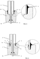
- figure 2 shows a gas sampler 2, which is associated to the porous filter 1 by means of an adhesive material 3.
- this adhesive material 3 is located at the outer part of the gas sampler 2, as shown in figure 3 , which represents this detail in sectional view in figure 2 .
- the porous ceramic filter 1 comprises a back face 1b, which is the lower end of the immersion probe A, besides a front face 1a, which is opposed to the back face 1b and comprises a cavity for association of the gas sampler 2.
- the gas sampler 2 has a gas injection tube 4 inside it, which is used for injecting inert gas carrier and its sequent sampling for analysis.
- an adhesive material 3 is added, which associates the porous ceramic filter 1 upon adhering to its cavity, as presented by detail 5. It should be noted that it is at this point that the association if weakest, and that is where most of the problems mentioned before occur.
- the present invention is illustrated in sectional view in figure 4 , presents an immersion probe A for analysis of gases, which comprises a porous ceramic filter 1, which preferably has a specific shape with a protruding cylinder body at its central part.
- This porous ceramic filter 1 further has a back face 1b, which is the end of the immersion probe A for analysis of gasses, besides a front face 1a opposite the back face 1b.
- the front face 1a comprises a groove 7 that associates the porous ceramic filter 1 to a gas sampler 2, which is preferably cylindrical as well.
- the groove 7 comprises an increase in the body of the porous ceramic filter 1 protruding into the gas sampler 2, the latter being higher, with respect to the front face 1a, than the prior art, preferably between 6 and 10 mm, but with values ranging from 5 to 20 mm.
- the gas sampler 2 which preferably has a concentric gas injection tube 4 inside it, is associated to the porous ceramic filter 1 in this groove 7 and, for this reason, the gas sampler 2 comprises an end portion 6 that separates the inner portion 8 from an outer portion 9.
- the inner portions 8 and 9 form, preferably, planes parallel to the faces 1a and 1b, which define the relative heights of these portions. These relative heights between the planes of the inner portions 8 and 9 may be different or, preferably according to the invention, may have the same height for greater resistivity and better mechanical support of the porous ceramic filter 1. Besides, the mechanical support between the porous ceramic filter 1 and the gas sampler 2 is achieved by means of an adhesive material 3, which aids in providing better mechanical support to the assembly than the prior art because it is located at both the internal portion 8 and the external portion 9 of the groove 7.
- one forms a double sealing of the assembly between the porous ceramic filter 1 and the gas sampler 2, illustrated by the details 5 and 5a in figure 4 , the sealing being considered double because the sealing is present both in the outer portion 9 and the inner portion 8 of the gas sampler 2.
- this double sealing in the case of a possible failure in the first sealing caused by a crack or break in this association of the porous ceramic filter 1 to the gas sampler2, there is still the second sealing, which prevents the molten metal C from getting into the gas sampler 2, thus preventing error or failure in the detection of the immersion probe A for analysis of gases.
- Another advantage of the configuration of the filter with double sealing is that the latter enables association of the porous ceramic filter 1 with the gas sampler 2 with a smaller amount of adhesive material 3.
- This adhesive material 3 usually a ceramic material or cement, is harmful to the immersion probe A, because both are hygroscopic and the water present therein implies less accurate detections. Therefore, the use of a smaller amount thereof may be considered one more advantage of the present invention.
Landscapes
- Life Sciences & Earth Sciences (AREA)
- Health & Medical Sciences (AREA)
- Chemical & Material Sciences (AREA)
- General Physics & Mathematics (AREA)
- Pathology (AREA)
- Analytical Chemistry (AREA)
- Biochemistry (AREA)
- General Health & Medical Sciences (AREA)
- Physics & Mathematics (AREA)
- Immunology (AREA)
- Engineering & Computer Science (AREA)
- Hydrology & Water Resources (AREA)
- Biomedical Technology (AREA)
- Molecular Biology (AREA)
- Food Science & Technology (AREA)
- Medicinal Chemistry (AREA)
- Sampling And Sample Adjustment (AREA)
- Investigating And Analyzing Materials By Characteristic Methods (AREA)
Claims (11)
- Tauchsonde zur Analyse von Gasen in geschmolzenem Metall, die mindestens umfasst:- einen Gasprobennehmer (2), der einen Endteil (6) aufweist;- ein poröses Keramikfilter (1), das eine Nut (7) enthält, die in der Lage ist, den Endteil (6) des Gasprobennehmers (2) mit dem porösen Keramikfilter (1) zu verbinden;wobei der Gasprobennehmer (2) einen Innenteil (8) und einen Außenteil (9) mit Bezug auf den Endteil (6) hat, wobei die Nut (7) den Innenteil (8) vom Außenteil (9) trennt und so ausgelegt ist, dass das Keramikmaterial des porösen keramischen Filters (1) den Endteil (6) des Gasprobennehmers (2) von seinem Innenteil (8) bis zu seinem Außenteil (9) umgibt und wobei die Sonde ferner Haftmaterial (5, 5a) zur mechanischen Stützung des Gasprobennehmers (2) enthält, das sich an der Verbindung des Endteils (6) mit der Nut (7) befindet, dadurch gekennzeichnet, dass das Haftmaterial (5, 5a) sich sowohl im Innenteil (8) als auch im Außenteil (9) des Gasprobennehmers (2) befindet.
- Tauchsonde zur Analyse von Gasen in geschmolzenem Metall nach Anspruch 1, wobei das poröse keramische Filter (1) im Innenteil (8) des Gasprobennehmers (2) eine Vergrößerung seines Körpers aufweist.
- Tauchsonde zur Analyse von Gasen in geschmolzenem Metall nach Anspruch 2, wobei die Nut (7) des porösen keramischen Filters (1) eine Vorderfläche (1a) hat, die eine Ebene parallel zu der Ebene definiert, die durch den Innenteil (8) definiert wird, und zur Ebene, die durch den Außenteil (9) definiert wird.
- Tauchsonde zur Analyse von Gasen in geschmolzenem Metall nach Anspruch 3, wobei der Innenteil (8) als auch der Außenteil (9) dieselbe Höhe wie die Ebene haben, die durch die Vorderfläche (1a) des porösen keramischen Filters (1) definiert wird.
- Tauchsonde zur Analyse von Gasen in geschmolzenem Metall nach Anspruch 3, wobei die Ebenen, die durch den Innenteil (8) und den Außenteil (9) definiert werden, unterschiedliche Höhen mit Bezug auf die Ebene haben, die durch die Vorderfläche (1a) des porösen keramischen Filters (1) definiert wird.
- Tauchsonde zur Analyse von Gasen in geschmolzenem Metall nach den Ansprüchen 1 bis 5, wobei der Gasprobennehmer (2) eine zylindrische Form hat.
- Tauchsonde zur Analyse von Gasen in geschmolzenem Metall nach den Ansprüchen 1 bis 6, wobei der Gasprobennehmer (2) ein Gasinjektionsrohr (4) in seinem Innenteil (8) hat.
- Tauchsonde zur Analyse von Gasen in geschmolzenem Metall nach den Ansprüchen 1 bis 7, wobei das Gasinjektionsrohr (4) eine zylindrische Form hat.
- Tauchsonde zur Analyse von Gasen in geschmolzenem Metall nach den Ansprüchen 1 bis 8, wobei der Gasprobennehmer (2) und das Gasinjektionsrohr (4) konzentrisch sind.
- Tauchsonde zur Analyse von Gasen in geschmolzenem Metall nach den Ansprüchen 1 bis 9, wobei der Gasprobennehmer (2) aus Quarz ausgebildet ist.
- Tauchsonde zur Analyse von Gasen in geschmolzenem Metall nach den Ansprüchen 8 bis 10, wobei das Gasinjektionsrohr (4) aus Quarz ausgebildet ist.
Applications Claiming Priority (1)
| Application Number | Priority Date | Filing Date | Title |
|---|---|---|---|
| BRPI1103889-6A BRPI1103889B1 (pt) | 2011-08-17 | 2011-08-17 | Sonda de imersão para análise de gases em metal fundido |
Publications (2)
| Publication Number | Publication Date |
|---|---|
| EP2559990A1 EP2559990A1 (de) | 2013-02-20 |
| EP2559990B1 true EP2559990B1 (de) | 2022-02-23 |
Family
ID=46940220
Family Applications (1)
| Application Number | Title | Priority Date | Filing Date |
|---|---|---|---|
| EP12180502.2A Active EP2559990B1 (de) | 2011-08-17 | 2012-08-15 | Tauchsonde zur Analyse von Gasen in geschmolzenem Metall |
Country Status (6)
| Country | Link |
|---|---|
| US (1) | US8833139B2 (de) |
| EP (1) | EP2559990B1 (de) |
| BR (1) | BRPI1103889B1 (de) |
| DK (1) | DK2559990T3 (de) |
| ES (1) | ES2913804T3 (de) |
| PL (1) | PL2559990T3 (de) |
Families Citing this family (3)
| Publication number | Priority date | Publication date | Assignee | Title |
|---|---|---|---|---|
| US8720287B2 (en) * | 2011-02-17 | 2014-05-13 | Perry Haney | Gas trap |
| US9879489B2 (en) | 2013-08-14 | 2018-01-30 | David L. Shanks | Floating gas trap system using agitation |
| USD749137S1 (en) | 2014-08-08 | 2016-02-09 | Floatair Agitator Limited Liability Company | Impeller for fluid agitation |
Family Cites Families (9)
| Publication number | Priority date | Publication date | Assignee | Title |
|---|---|---|---|---|
| SE336434B (de) * | 1970-08-27 | 1971-07-05 | Asea Ab | |
| JPS6358153A (ja) * | 1986-08-28 | 1988-03-12 | Nippon Mining Co Ltd | 真空中の溶融金属中の微量酸素を測定する方法 |
| ATE72334T1 (de) | 1987-03-18 | 1992-02-15 | Electro Nite | Vorrichtung und verfahren zur messung des gasgehaltes eines fluessigen metalls und sonde dafuer. |
| CN1047444C (zh) * | 1993-09-03 | 1999-12-15 | 日本贺利氏电测骑士公司 | 测定钢水中碳、氢和氮浓度的方法和装置 |
| FR2718375B1 (fr) * | 1994-04-08 | 1996-06-21 | Soled Ind | Dispositif de prélèvement d'échantillon de métal en fusion. |
| US6216526B1 (en) | 1998-12-16 | 2001-04-17 | Midwest Instrument Co., Inc. | Gas sampler for molten metal and method |
| DE102005011181A1 (de) * | 2005-03-09 | 2006-09-14 | Heraeus Electro-Nite International N.V. | Vorrichtung zum Messen des Gasgehaltes in einer Metallschmelze |
| DE102007063673B4 (de) * | 2007-07-10 | 2018-02-08 | Heraeus Electro-Nite International N.V. | Messverfahren |
| US8689650B2 (en) * | 2009-04-28 | 2014-04-08 | Heraeus Electro-Nite Co., Llc | Immersible oxygen sensor for molten metals |
-
2011
- 2011-08-17 BR BRPI1103889-6A patent/BRPI1103889B1/pt active IP Right Grant
-
2012
- 2012-08-14 US US13/585,530 patent/US8833139B2/en active Active
- 2012-08-15 DK DK12180502.2T patent/DK2559990T3/da active
- 2012-08-15 PL PL12180502.2T patent/PL2559990T3/pl unknown
- 2012-08-15 ES ES12180502T patent/ES2913804T3/es active Active
- 2012-08-15 EP EP12180502.2A patent/EP2559990B1/de active Active
Also Published As
| Publication number | Publication date |
|---|---|
| US20130042666A1 (en) | 2013-02-21 |
| EP2559990A1 (de) | 2013-02-20 |
| BRPI1103889A2 (pt) | 2014-03-25 |
| DK2559990T3 (en) | 2022-05-16 |
| BRPI1103889B1 (pt) | 2020-09-24 |
| PL2559990T3 (pl) | 2022-08-08 |
| US8833139B2 (en) | 2014-09-16 |
| ES2913804T3 (es) | 2022-06-06 |
Similar Documents
| Publication | Publication Date | Title |
|---|---|---|
| CN102788715B (zh) | 从熔点高于600℃的熔融物中采样的采样装置以及采样方法 | |
| US8833139B2 (en) | Immersion probe for analysis of gases in molten metal | |
| US9176027B2 (en) | Device for measuring parameters or for taking samples in molten iron or steel | |
| EP3241024B1 (de) | Tauchsonde und anordnung einer tauchsublanze und tauchsonde für einen konverterofen | |
| US8844386B2 (en) | Method and apparatus for analyzing samples of metal melts | |
| RU2712618C1 (ru) | Пробоотборники расплавленного металла для применений с высоким и низким содержанием кислорода | |
| US8152978B2 (en) | Apparatus and method for measuring hydrogen concentration in molten metals | |
| KR100951877B1 (ko) | 직송달 시료채취기 | |
| US11684970B2 (en) | Immersion sensor for determining chemical composition of molten metal | |
| AU2016201732B2 (en) | Immersion device for molten metal and method | |
| JP3467514B2 (ja) | 溶融金属の試料採取装置、溶融金属の試料採取装置用部材及び試料採取方法 | |
| KR20130077635A (ko) | 용융금속 및 슬래그 건전시료를 동시에 채취하는 복합프로브 | |
| KR101269147B1 (ko) | 비표면적 측정 장치용 시료셀 | |
| CN103154698B (zh) | 双重采样复合探头 | |
| CN101975689B (zh) | 一次制备多个液态金属试样的方法 | |
| CN207318169U (zh) | 一种适用于氧氮氢分析仪检测钢水氮含量的取样装置 | |
| JP2648925B2 (ja) | 溶鋼中の水素分析方法および装置 | |
| KR100979121B1 (ko) | 용선 프로브용 시료채취기 | |
| CN105043829A (zh) | 一种金属钙化学分析用试样的制样方法 | |
| CN107796666A (zh) | 一种氧氮氢分析仪检测钢水氮含量的取样装置及方法 | |
| KR100727845B1 (ko) | 프로브용 센서 고정체 | |
| KR20130002199A (ko) | 슬래그의 잔류 수소 분석용 샘플 채취기 | |
| KR20100107750A (ko) | 용강 샘플러 |
Legal Events
| Date | Code | Title | Description |
|---|---|---|---|
| PUAI | Public reference made under article 153(3) epc to a published international application that has entered the european phase |
Free format text: ORIGINAL CODE: 0009012 |
|
| AK | Designated contracting states |
Kind code of ref document: A1 Designated state(s): AL AT BE BG CH CY CZ DE DK EE ES FI FR GB GR HR HU IE IS IT LI LT LU LV MC MK MT NL NO PL PT RO RS SE SI SK SM TR |
|
| AX | Request for extension of the european patent |
Extension state: BA ME |
|
| 17P | Request for examination filed |
Effective date: 20130816 |
|
| RBV | Designated contracting states (corrected) |
Designated state(s): AL AT BE BG CH CY CZ DE DK EE ES FI FR GB GR HR HU IE IS IT LI LT LU LV MC MK MT NL NO PL PT RO RS SE SI SK SM TR |
|
| 17Q | First examination report despatched |
Effective date: 20150319 |
|
| STAA | Information on the status of an ep patent application or granted ep patent |
Free format text: STATUS: EXAMINATION IS IN PROGRESS |
|
| RAP1 | Party data changed (applicant data changed or rights of an application transferred) |
Owner name: VESUVIUS REFRATARIOS LTDA. |
|
| GRAP | Despatch of communication of intention to grant a patent |
Free format text: ORIGINAL CODE: EPIDOSNIGR1 |
|
| STAA | Information on the status of an ep patent application or granted ep patent |
Free format text: STATUS: GRANT OF PATENT IS INTENDED |
|
| INTG | Intention to grant announced |
Effective date: 20210914 |
|
| GRAS | Grant fee paid |
Free format text: ORIGINAL CODE: EPIDOSNIGR3 |
|
| GRAA | (expected) grant |
Free format text: ORIGINAL CODE: 0009210 |
|
| STAA | Information on the status of an ep patent application or granted ep patent |
Free format text: STATUS: THE PATENT HAS BEEN GRANTED |
|
| AK | Designated contracting states |
Kind code of ref document: B1 Designated state(s): AL AT BE BG CH CY CZ DE DK EE ES FI FR GB GR HR HU IE IS IT LI LT LU LV MC MK MT NL NO PL PT RO RS SE SI SK SM TR |
|
| REG | Reference to a national code |
Ref country code: GB Ref legal event code: FG4D |
|
| REG | Reference to a national code |
Ref country code: CH Ref legal event code: EP |
|
| REG | Reference to a national code |
Ref country code: DE Ref legal event code: R096 Ref document number: 602012077713 Country of ref document: DE |
|
| REG | Reference to a national code |
Ref country code: AT Ref legal event code: REF Ref document number: 1470841 Country of ref document: AT Kind code of ref document: T Effective date: 20220315 |
|
| REG | Reference to a national code |
Ref country code: IE Ref legal event code: FG4D |
|
| REG | Reference to a national code |
Ref country code: RO Ref legal event code: EPE |
|
| REG | Reference to a national code |
Ref country code: NL Ref legal event code: FP |
|
| REG | Reference to a national code |
Ref country code: DK Ref legal event code: T3 Effective date: 20220509 |
|
| REG | Reference to a national code |
Ref country code: ES Ref legal event code: FG2A Ref document number: 2913804 Country of ref document: ES Kind code of ref document: T3 Effective date: 20220606 |
|
| REG | Reference to a national code |
Ref country code: LT Ref legal event code: MG9D |
|
| PG25 | Lapsed in a contracting state [announced via postgrant information from national office to epo] |
Ref country code: SE Free format text: LAPSE BECAUSE OF FAILURE TO SUBMIT A TRANSLATION OF THE DESCRIPTION OR TO PAY THE FEE WITHIN THE PRESCRIBED TIME-LIMIT Effective date: 20220223 Ref country code: RS Free format text: LAPSE BECAUSE OF FAILURE TO SUBMIT A TRANSLATION OF THE DESCRIPTION OR TO PAY THE FEE WITHIN THE PRESCRIBED TIME-LIMIT Effective date: 20220223 Ref country code: PT Free format text: LAPSE BECAUSE OF FAILURE TO SUBMIT A TRANSLATION OF THE DESCRIPTION OR TO PAY THE FEE WITHIN THE PRESCRIBED TIME-LIMIT Effective date: 20220623 Ref country code: NO Free format text: LAPSE BECAUSE OF FAILURE TO SUBMIT A TRANSLATION OF THE DESCRIPTION OR TO PAY THE FEE WITHIN THE PRESCRIBED TIME-LIMIT Effective date: 20220523 Ref country code: LT Free format text: LAPSE BECAUSE OF FAILURE TO SUBMIT A TRANSLATION OF THE DESCRIPTION OR TO PAY THE FEE WITHIN THE PRESCRIBED TIME-LIMIT Effective date: 20220223 Ref country code: HR Free format text: LAPSE BECAUSE OF FAILURE TO SUBMIT A TRANSLATION OF THE DESCRIPTION OR TO PAY THE FEE WITHIN THE PRESCRIBED TIME-LIMIT Effective date: 20220223 Ref country code: BG Free format text: LAPSE BECAUSE OF FAILURE TO SUBMIT A TRANSLATION OF THE DESCRIPTION OR TO PAY THE FEE WITHIN THE PRESCRIBED TIME-LIMIT Effective date: 20220523 |
|
| PG25 | Lapsed in a contracting state [announced via postgrant information from national office to epo] |
Ref country code: LV Free format text: LAPSE BECAUSE OF FAILURE TO SUBMIT A TRANSLATION OF THE DESCRIPTION OR TO PAY THE FEE WITHIN THE PRESCRIBED TIME-LIMIT Effective date: 20220223 Ref country code: GR Free format text: LAPSE BECAUSE OF FAILURE TO SUBMIT A TRANSLATION OF THE DESCRIPTION OR TO PAY THE FEE WITHIN THE PRESCRIBED TIME-LIMIT Effective date: 20220524 Ref country code: FI Free format text: LAPSE BECAUSE OF FAILURE TO SUBMIT A TRANSLATION OF THE DESCRIPTION OR TO PAY THE FEE WITHIN THE PRESCRIBED TIME-LIMIT Effective date: 20220223 |
|
| PG25 | Lapsed in a contracting state [announced via postgrant information from national office to epo] |
Ref country code: IS Free format text: LAPSE BECAUSE OF FAILURE TO SUBMIT A TRANSLATION OF THE DESCRIPTION OR TO PAY THE FEE WITHIN THE PRESCRIBED TIME-LIMIT Effective date: 20220623 |
|
| PG25 | Lapsed in a contracting state [announced via postgrant information from national office to epo] |
Ref country code: SM Free format text: LAPSE BECAUSE OF FAILURE TO SUBMIT A TRANSLATION OF THE DESCRIPTION OR TO PAY THE FEE WITHIN THE PRESCRIBED TIME-LIMIT Effective date: 20220223 Ref country code: SK Free format text: LAPSE BECAUSE OF FAILURE TO SUBMIT A TRANSLATION OF THE DESCRIPTION OR TO PAY THE FEE WITHIN THE PRESCRIBED TIME-LIMIT Effective date: 20220223 Ref country code: EE Free format text: LAPSE BECAUSE OF FAILURE TO SUBMIT A TRANSLATION OF THE DESCRIPTION OR TO PAY THE FEE WITHIN THE PRESCRIBED TIME-LIMIT Effective date: 20220223 |
|
| REG | Reference to a national code |
Ref country code: DE Ref legal event code: R097 Ref document number: 602012077713 Country of ref document: DE |
|
| PG25 | Lapsed in a contracting state [announced via postgrant information from national office to epo] |
Ref country code: AL Free format text: LAPSE BECAUSE OF FAILURE TO SUBMIT A TRANSLATION OF THE DESCRIPTION OR TO PAY THE FEE WITHIN THE PRESCRIBED TIME-LIMIT Effective date: 20220223 |
|
| PLBE | No opposition filed within time limit |
Free format text: ORIGINAL CODE: 0009261 |
|
| STAA | Information on the status of an ep patent application or granted ep patent |
Free format text: STATUS: NO OPPOSITION FILED WITHIN TIME LIMIT |
|
| 26N | No opposition filed |
Effective date: 20221124 |
|
| PG25 | Lapsed in a contracting state [announced via postgrant information from national office to epo] |
Ref country code: SI Free format text: LAPSE BECAUSE OF FAILURE TO SUBMIT A TRANSLATION OF THE DESCRIPTION OR TO PAY THE FEE WITHIN THE PRESCRIBED TIME-LIMIT Effective date: 20220223 |
|
| PG25 | Lapsed in a contracting state [announced via postgrant information from national office to epo] |
Ref country code: MC Free format text: LAPSE BECAUSE OF FAILURE TO SUBMIT A TRANSLATION OF THE DESCRIPTION OR TO PAY THE FEE WITHIN THE PRESCRIBED TIME-LIMIT Effective date: 20220223 |
|
| REG | Reference to a national code |
Ref country code: CH Ref legal event code: PL |
|
| PG25 | Lapsed in a contracting state [announced via postgrant information from national office to epo] |
Ref country code: LI Free format text: LAPSE BECAUSE OF NON-PAYMENT OF DUE FEES Effective date: 20220831 Ref country code: CH Free format text: LAPSE BECAUSE OF NON-PAYMENT OF DUE FEES Effective date: 20220831 |
|
| P01 | Opt-out of the competence of the unified patent court (upc) registered |
Effective date: 20230524 |
|
| REG | Reference to a national code |
Ref country code: AT Ref legal event code: UEP Ref document number: 1470841 Country of ref document: AT Kind code of ref document: T Effective date: 20220223 |
|
| PG25 | Lapsed in a contracting state [announced via postgrant information from national office to epo] |
Ref country code: IE Free format text: LAPSE BECAUSE OF NON-PAYMENT OF DUE FEES Effective date: 20220815 |
|
| PG25 | Lapsed in a contracting state [announced via postgrant information from national office to epo] |
Ref country code: HU Free format text: LAPSE BECAUSE OF FAILURE TO SUBMIT A TRANSLATION OF THE DESCRIPTION OR TO PAY THE FEE WITHIN THE PRESCRIBED TIME-LIMIT; INVALID AB INITIO Effective date: 20120815 |
|
| PG25 | Lapsed in a contracting state [announced via postgrant information from national office to epo] |
Ref country code: CY Free format text: LAPSE BECAUSE OF FAILURE TO SUBMIT A TRANSLATION OF THE DESCRIPTION OR TO PAY THE FEE WITHIN THE PRESCRIBED TIME-LIMIT Effective date: 20220223 |
|
| PG25 | Lapsed in a contracting state [announced via postgrant information from national office to epo] |
Ref country code: MK Free format text: LAPSE BECAUSE OF FAILURE TO SUBMIT A TRANSLATION OF THE DESCRIPTION OR TO PAY THE FEE WITHIN THE PRESCRIBED TIME-LIMIT Effective date: 20220223 |
|
| PG25 | Lapsed in a contracting state [announced via postgrant information from national office to epo] |
Ref country code: MT Free format text: LAPSE BECAUSE OF FAILURE TO SUBMIT A TRANSLATION OF THE DESCRIPTION OR TO PAY THE FEE WITHIN THE PRESCRIBED TIME-LIMIT Effective date: 20220223 |
|
| PGFP | Annual fee paid to national office [announced via postgrant information from national office to epo] |
Ref country code: LU Payment date: 20250827 Year of fee payment: 14 Ref country code: NL Payment date: 20250826 Year of fee payment: 14 |
|
| PGFP | Annual fee paid to national office [announced via postgrant information from national office to epo] |
Ref country code: ES Payment date: 20250901 Year of fee payment: 14 |
|
| PGFP | Annual fee paid to national office [announced via postgrant information from national office to epo] |
Ref country code: DK Payment date: 20250825 Year of fee payment: 14 Ref country code: DE Payment date: 20250827 Year of fee payment: 14 |
|
| PGFP | Annual fee paid to national office [announced via postgrant information from national office to epo] |
Ref country code: PL Payment date: 20250723 Year of fee payment: 14 Ref country code: IT Payment date: 20250820 Year of fee payment: 14 Ref country code: TR Payment date: 20250721 Year of fee payment: 14 |
|
| PGFP | Annual fee paid to national office [announced via postgrant information from national office to epo] |
Ref country code: BE Payment date: 20250827 Year of fee payment: 14 Ref country code: GB Payment date: 20250827 Year of fee payment: 14 |
|
| PGFP | Annual fee paid to national office [announced via postgrant information from national office to epo] |
Ref country code: FR Payment date: 20250825 Year of fee payment: 14 Ref country code: AT Payment date: 20250827 Year of fee payment: 14 |
|
| PGFP | Annual fee paid to national office [announced via postgrant information from national office to epo] |
Ref country code: CZ Payment date: 20250724 Year of fee payment: 14 |
|
| PGFP | Annual fee paid to national office [announced via postgrant information from national office to epo] |
Ref country code: RO Payment date: 20250725 Year of fee payment: 14 |