EP3241024B1 - Tauchsonde und anordnung einer tauchsublanze und tauchsonde für einen konverterofen - Google Patents
Tauchsonde und anordnung einer tauchsublanze und tauchsonde für einen konverterofen Download PDFInfo
- Publication number
- EP3241024B1 EP3241024B1 EP15822950.0A EP15822950A EP3241024B1 EP 3241024 B1 EP3241024 B1 EP 3241024B1 EP 15822950 A EP15822950 A EP 15822950A EP 3241024 B1 EP3241024 B1 EP 3241024B1
- Authority
- EP
- European Patent Office
- Prior art keywords
- immersion
- sublance
- immersion probe
- probe
- assembly
- Prior art date
- Legal status (The legal status is an assumption and is not a legal conclusion. Google has not performed a legal analysis and makes no representation as to the accuracy of the status listed.)
- Active
Links
Images




Classifications
-
- C—CHEMISTRY; METALLURGY
- C21—METALLURGY OF IRON
- C21C—PROCESSING OF PIG-IRON, e.g. REFINING, MANUFACTURE OF WROUGHT-IRON OR STEEL; TREATMENT IN MOLTEN STATE OF FERROUS ALLOYS
- C21C5/00—Manufacture of carbon-steel, e.g. plain mild steel, medium carbon steel or cast steel or stainless steel
- C21C5/28—Manufacture of steel in the converter
- C21C5/42—Constructional features of converters
- C21C5/46—Details or accessories
- C21C5/4673—Measuring and sampling devices
-
- F—MECHANICAL ENGINEERING; LIGHTING; HEATING; WEAPONS; BLASTING
- F27—FURNACES; KILNS; OVENS; RETORTS
- F27D—DETAILS OR ACCESSORIES OF FURNACES, KILNS, OVENS OR RETORTS, IN SO FAR AS THEY ARE OF KINDS OCCURRING IN MORE THAN ONE KIND OF FURNACE
- F27D19/00—Arrangements of controlling devices
-
- G—PHYSICS
- G01—MEASURING; TESTING
- G01K—MEASURING TEMPERATURE; MEASURING QUANTITY OF HEAT; THERMALLY-SENSITIVE ELEMENTS NOT OTHERWISE PROVIDED FOR
- G01K13/00—Thermometers specially adapted for specific purposes
- G01K13/12—Thermometers specially adapted for specific purposes combined with sampling devices for measuring temperatures of samples of materials
-
- G—PHYSICS
- G01—MEASURING; TESTING
- G01N—INVESTIGATING OR ANALYSING MATERIALS BY DETERMINING THEIR CHEMICAL OR PHYSICAL PROPERTIES
- G01N1/00—Sampling; Preparing specimens for investigation
- G01N1/02—Devices for withdrawing samples
- G01N1/10—Devices for withdrawing samples in the liquid or fluent state
- G01N1/12—Dippers; Dredgers
- G01N1/125—Dippers; Dredgers adapted for sampling molten metals
-
- G—PHYSICS
- G01—MEASURING; TESTING
- G01N—INVESTIGATING OR ANALYSING MATERIALS BY DETERMINING THEIR CHEMICAL OR PHYSICAL PROPERTIES
- G01N1/00—Sampling; Preparing specimens for investigation
- G01N1/02—Devices for withdrawing samples
- G01N1/10—Devices for withdrawing samples in the liquid or fluent state
- G01N1/14—Suction devices, e.g. pumps; Ejector devices
- G01N1/1409—Suction devices, e.g. pumps; Ejector devices adapted for sampling molten metals
-
- G—PHYSICS
- G01—MEASURING; TESTING
- G01N—INVESTIGATING OR ANALYSING MATERIALS BY DETERMINING THEIR CHEMICAL OR PHYSICAL PROPERTIES
- G01N33/00—Investigating or analysing materials by specific methods not covered by groups G01N1/00 - G01N31/00
- G01N33/20—Metals
- G01N33/205—Metals in liquid state, e.g. molten metals
-
- C—CHEMISTRY; METALLURGY
- C21—METALLURGY OF IRON
- C21C—PROCESSING OF PIG-IRON, e.g. REFINING, MANUFACTURE OF WROUGHT-IRON OR STEEL; TREATMENT IN MOLTEN STATE OF FERROUS ALLOYS
- C21C5/00—Manufacture of carbon-steel, e.g. plain mild steel, medium carbon steel or cast steel or stainless steel
- C21C5/52—Manufacture of steel in electric furnaces
- C21C2005/5288—Measuring or sampling devices
-
- C—CHEMISTRY; METALLURGY
- C21—METALLURGY OF IRON
- C21C—PROCESSING OF PIG-IRON, e.g. REFINING, MANUFACTURE OF WROUGHT-IRON OR STEEL; TREATMENT IN MOLTEN STATE OF FERROUS ALLOYS
- C21C5/00—Manufacture of carbon-steel, e.g. plain mild steel, medium carbon steel or cast steel or stainless steel
- C21C5/52—Manufacture of steel in electric furnaces
- C21C5/54—Processes yielding slags of special composition
-
- F—MECHANICAL ENGINEERING; LIGHTING; HEATING; WEAPONS; BLASTING
- F27—FURNACES; KILNS; OVENS; RETORTS
- F27D—DETAILS OR ACCESSORIES OF FURNACES, KILNS, OVENS OR RETORTS, IN SO FAR AS THEY ARE OF KINDS OCCURRING IN MORE THAN ONE KIND OF FURNACE
- F27D19/00—Arrangements of controlling devices
- F27D2019/0003—Monitoring the temperature or a characteristic of the charge and using it as a controlling value
-
- F—MECHANICAL ENGINEERING; LIGHTING; HEATING; WEAPONS; BLASTING
- F27—FURNACES; KILNS; OVENS; RETORTS
- F27D—DETAILS OR ACCESSORIES OF FURNACES, KILNS, OVENS OR RETORTS, IN SO FAR AS THEY ARE OF KINDS OCCURRING IN MORE THAN ONE KIND OF FURNACE
- F27D19/00—Arrangements of controlling devices
- F27D2019/0006—Monitoring the characteristics (composition, quantities, temperature, pressure) of at least one of the gases of the kiln atmosphere and using it as a controlling value
-
- F—MECHANICAL ENGINEERING; LIGHTING; HEATING; WEAPONS; BLASTING
- F27—FURNACES; KILNS; OVENS; RETORTS
- F27D—DETAILS OR ACCESSORIES OF FURNACES, KILNS, OVENS OR RETORTS, IN SO FAR AS THEY ARE OF KINDS OCCURRING IN MORE THAN ONE KIND OF FURNACE
- F27D19/00—Arrangements of controlling devices
- F27D2019/0028—Regulation
-
- F—MECHANICAL ENGINEERING; LIGHTING; HEATING; WEAPONS; BLASTING
- F27—FURNACES; KILNS; OVENS; RETORTS
- F27D—DETAILS OR ACCESSORIES OF FURNACES, KILNS, OVENS OR RETORTS, IN SO FAR AS THEY ARE OF KINDS OCCURRING IN MORE THAN ONE KIND OF FURNACE
- F27D21/00—Arrangement of monitoring devices; Arrangement of safety devices
- F27D21/0014—Devices for monitoring temperature
-
- Y—GENERAL TAGGING OF NEW TECHNOLOGICAL DEVELOPMENTS; GENERAL TAGGING OF CROSS-SECTIONAL TECHNOLOGIES SPANNING OVER SEVERAL SECTIONS OF THE IPC; TECHNICAL SUBJECTS COVERED BY FORMER USPC CROSS-REFERENCE ART COLLECTIONS [XRACs] AND DIGESTS
- Y02—TECHNOLOGIES OR APPLICATIONS FOR MITIGATION OR ADAPTATION AGAINST CLIMATE CHANGE
- Y02P—CLIMATE CHANGE MITIGATION TECHNOLOGIES IN THE PRODUCTION OR PROCESSING OF GOODS
- Y02P10/00—Technologies related to metal processing
- Y02P10/20—Recycling
Definitions
- the present invention relates to an immersion probe and an assembly of immersion sublance and immersion probe to perform measurements and/or take samples out of a converter furnace filled with molten metal, said immersion probe being configured to feature a variable length.
- Immersion sublances and immersion probes are broadly used in converter furnaces during steelmaking processes. Typically, pig iron and scrap metal are discharged into the converter furnace, which fuses them together at a high temperature (1600 to 1750°C), thus producing steel.
- the molten metal has to be submitted to several chemical analyses.
- the aim is to monitor all the chemical elements contained in the steel, for example by controlling, among others, the carbon, carbon equivalents and silicon concentration, or by monitoring the hardness, resistance, machinability, temperature, oxidation level.
- Such chemical analyses are performed by means of sensing or sampling the molten metal, those operations being performed by sensors located at the end of an immersion probe.
- a blowing lance is used to blow oxygen inside the converter furnace at supersonic speed onto molten slag and molten metal.
- the assembly of immersion sublance and immersion probe is inserted from the external environment into the inside of the converter furnace following a longitudinal direction, such that only the immersion probe of said assembly is submerged into molten slag and subsequently into molten metal.
- the immersion probe is able to perform measurements and/or take samples of molten metal by means of sensors or sampling chambers.
- the assembly of immersion sublance and probe is taken out of the converter furnace, and the immersion probe is then disconnected from the immersion sublance and then discarded.
- connection of the immersion probe to the immersion sublance is performed before the insertion of the assembly into the converter furnace, said connection being partially automated.
- the immersion probe is used only once during the immersion and/or measurement process.
- the immersion sublance can be reused, for it is provided with a longer service life.
- a deformed immersion sublance can present connection problems with a new immersion probe, resulting in clearance between the sublance holder and the immersion probe. Such characteristic is not desirable, as it can lead to various problems.
- the immersion probe structure is made out of cardboard and does not possess precise dimensions, observation has been made that it cannot completely cover the immersion sublance holder. Furthermore, depending on the climatic conditions as well as the storage location of the immersion probes, it is known that deformations can occur on the cardboard constituting the probes casing, creating radial or longitudinal variations. Considering this problem, it is known that when the assembly of immersion sublance and immersion probe is inserted into the converter furnace, some molten metal splashes might land on the sublance holder, making the connection to a new immersion probe difficult.
- the European Patent EP-A1-69433 describes a sublance presenting a fixed upper end and a lower end which can rotate. It specifically discloses that the lower portion of the immersion sublance gets deformed after the first immersion in molten metal, then the sublance is taken out of the converter furnace and its lower end is rotated 180°. After said rotation, the sublance is then immersed anew. According to the teachings of European Patent EP-A1-69433 , this feature allows the lower portion to come back to its original position (before the first immersions).
- the first aim of the present invention is to provide an immersion probe enabling a greater connection efficiency with the immersion sublance holder.
- the second aim of the present invention is to provide an immersion probe that can be connected to the immersion sublances currently commercialized without any need to adapt them.
- Another aim of the present invention is to provide an immersion probe that can be connected to immersion sublances with a variable connection length.
- Yet another aim of the present invention is to provide an immersion probe that can be connected to the immersion sublances that have been deformed by consecutive immersions into the converter furnace.
- the present invention also aims at providing an immersion probe that can prevent molten metal from sticking onto the immersion sublance holder.
- the present inventions aims at compensating the longitudinal and/or radial length variations of the immersion sublance upon connection.
- the aims of the present invention are achieved by means of an assembly of immersion sublance and immersion probe for a converter furnace, the sublance comprising a connecting end, the connecting end being configured so as to be coupled to a first coupling end of a sublance holder, said sublance holder extending longitudinally from the first coupling end to a second coupling end, said sublance holder being connected to the immersion probe by connecting means between the second coupling end of the sublance holder and an adjustable portion of the immersion probe.
- an immersion probe for a converter furnace comprising a casing and an adjustable portion, said casing featuring an internal cavity in order to receive an adjustable portion, said adjustable portion extending longitudinally along the internal cavity of the casing, from a connecting portion to a fixed portion, the connecting portion and fixed portion being associated to one another by means of an elastic portion, the elastic portion being configured so as to change the length of the adjustable portion once a first contact point has been established with the surface of the connecting portion.
- Figure 1 - illustrates an inside view of a converter furnace 100 used in steel industry for producing and refining steel.
- a blowing lance 30 is used inside the converter furnace 100, said blowing lance 30 being used for injecting oxygen at supersonic speed on molten slag 40 and molten metal 50.
- an assembly formed by an immersion sublance 1 connected to an immersion probe 2 can be observed, said assembly formed by said components being inserted into the inside of a converter furnace 100.
- the assembly of immersion sublance 1 and immersion probe 2 being configured so as to project itself longitudinally from the external environment into the direction of the inside of the converter furnace 100. More specifically, such projection is realized so that the immersion probe 2 is immersed into the molten metal 50 lying underneath the molten slag 40. When immersed, the immersion probe 2 performs measurements and/or takes samples of molten metal 50. Afterwards, it is disconnected from the sublance 1 and then discarded.
- the immersion sublance 1 is used for measurement of molten metal 50, this is realized by means of sensors 21 located at the end of the immersion probe 2 to be immersed in the molten metal 50.
- the sensors 21 are connected to a measuring instrument (not shown), located in the surrounding environment of the converter furnace 100.
- the connection between the sensors 21 and the measuring instrument (not shown) being realized by contact lines that run through the inside of the immersion probe 2 and immersion sublance 1 up to the external environment. After the measurement, the immersion probe 2 is disconnected from the sublance 1 and then discarded.
- the immersion sublance 1 is used to take molten metal 50 samples, it is observed that this is realized by means of a chamber 22 located at the end of the immersion probe 2 to be immersed in the molten metal 50. After the sampling, the molten metal 50 that has been collected is removed for further analysis, the immersion probe 2 being disconnected from the sublance 1 and then discarded.
- the immersion sublance 1 can simultaneously perform measuring and sampling of the molten metal 50, being characterized by the presence of a chamber 22 and sensors 21 as previously described.
- immersion sublance 1 and the immersion probe 2 are hereunder described separately.
- the connection of both elements to form the assembly of immersion sublance 1 and immersion probe 2 will be detailed later on.
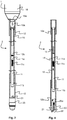
- an immersion sublance 1 can be observed in details from Figure 3 .
- Figures 3a and 3b show the mechanical structure of the immersion sublance 1, the sublance 1 being provided with a guide 16 and a sublance holder 10.
- the guide 16 presents a substantially cylindrical/tubular shape, being hollow along its whole length.
- Such a configuration provides the creation of an internal cavity for the passage of sensors 21 contact lines up to the surrounding environment and subsequently to a measuring instrument (not shown).
- the aforementioned guide 16 is preferably made from metallic materials able to withstand the typical high temperatures (1600 to 1750°C) of a converter furnace 100.
- the guide 16 on its portion that is closest to the converter furnace 100, features an end that will from now on be referred to as the guide connecting end 16a.
- the guide connecting end 16a is coupled to the sublance holder 10 of the sublance 1.
- the sublance holder 10 features a substantially cylindrical/tubular shape, said sublance holder 10 extending longitudinally from a first coupling end 10a in direction of the bottom of the converter furnace 100, down to a second coupling end 10b.
- first coupling end 10a is coupled to the guide connecting end 16a, such that the diameter of the guide connecting end 16a is equal to the external diameter of the first coupling end 10a, thus presenting a perfect coupling.
- the second coupling end 10b As will be described later, it must present an external diameter similar to the one of the internal cavity of the immersion probe 2.
- the internal cavity of the immersion sublance 1 located at the coupling end 10b can feature at least one holder contact line 25c, at least one of the lines 25c being arranged circumferentially around the inner wall of the cavity of the holder 10 coupling extremity 10b. At least one line 25c is connected to the measuring instrument located in the surrounding environment of the converter furnace 100.
- Figure 4 shows the mechanical structure of the immersion probe 2, said probe comprising a casing 12, an adjustable portion 11 and a sensing head 20.
- the immersion sublance 2 casing 12 is made from cardboard and can feature different lengths or diameters, these being dimensioned according to the user.
- the casing 12 is designed with several layers of cardboard, such that the casing 12 of the immersion probe 2 does not completely disintegrate when the immersion probe 2 is immersed into molten metal 50. Considering that the immersion lasts a few seconds, the structure of the casing 12 formed of several layers of cardboard is able to withstand the typical high temperatures (1600 to 1700°C) of a converter furnace 100.
- the casing 12 features a substantially cylindrical/tubular shape along its whole length, such a configuration allowing the creation of an internal cavity to receive the adjustable portion 11, the internal diameter being wide enough to receive the above referred to portion 11.
- said casing 12 comprises a casing upper portion 12a and a casing lower portion 12b. Considering that both portions 12a and 12b feature the same diameter, it is observed that an intermediate portion of the casing 12 features a smaller diameter.
- the casing 12 can feature a constant diameter along its whole length.
- the adjustable portion 11 it is observed from Figure 4 that it extends longitudinally along the inside of the internal cavity of the casing 12 from a connecting portion 11a to a fixed portion 11b.
- the connecting portion 11a being close to the casing upper portion 12a and the fixed portion 11b being close to the casing lower portion 12b.
- the connecting portion 11a and the fixed portion 11b being associated to one another by means of an elastic portion 11c, such that the adjustable portion 11 features a variable length.
- connecting portion 11a and the fixed portion 11b feature a substantially cylindrical/tubular shape comprising diameters smaller or equal to the internal cavity of the casing 12.
- the elastic portion 11c can be a spring, an elastic ring, an elastomer, or any other elastic material, able to compress and expand itself by means of applying a force once a first contact point P1 is established such as observed from Figures 5a-5e , 6a-6e and 7a-7e and that will be subsequently described in details.
- connection base 14 being located at the end of the connecting portion 11a that is closest to the bottom of the converter furnace 100.
- the connector 15 being located at the end of the connecting portion 11a that is closest to the top of the converter furnace 100.
- the connection base 14 being associated to the connector 15e and the elastic portion 11c.
- the Connector 15 projecting in the direction of the top of the converter furnace 100.
- the connector 15 is provided with at least one connector contact line 25b, at least one line 25b being circumferentially located around the surface of the connector 15. As will be described later, at least one contact line of the connector 25b will be connected to at least one contact line of the holder 25c.
- the connector 15 dimensions are such that it presents a substantially smaller diameter than the base 14, the connector 15 presenting a diameter smaller or equal to the diameter of the second coupling end 10b.
- the base 14 in turn presenting a diameter smaller or equal to the one of the second coupling end 10b.
- the fixed portion 11b In respect to the fixed portion 11b, as can be observed from Figure 4 , it projects itself towards the bottom of the converter furnace 100, the fixed portion 11b being coupled to the casing lower portion 12b. It is observed that the sensing head 20 is also coupled to the casing lower portion 12b.
- the sensing head 20 is provided with at least one sensor 21, that could either be a temperature sensor, an oxygen sensor, or any other sensor required for molten metal chemical analyses 50.
- At least one sensor 21 is provided with at least one sensor contact line 25a, the line 25a extending up to the connecting portion 11a, where is it then connected to at least one connector contact line 25b.
- the sensing head 20 can comprise a sampling chamber 22, said chamber being configured to collect molten metal 50 when the immersion probe is immersed, the collected molten metal 50 solidifying when the immersion probe 2 is taken out of the converter furnace 100.
- the user must connect a new immersion probe 2 to the immersion sublance 1, this constituting an assembly of immersion sublance 1 and immersion probe 2.
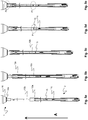
- Figures 5a and 6a illustrate a case where the immersion sublance 1 and the immersion probe 2 are completely disconnected. It is observed that an arrow A represents the direction of connection realized by the user for said connection of the elements.
- the sublance holder 10 of the immersion sublance 1 is connected to the immersion probe 2. More specifically, the second coupling end 10b is projected into the internal cavity of the immersion sublance 2 towards the adjustable portion 11, as observed from Figure 5b . As previously noted, the external diameter of the second coupling end 10b is smaller or equal to the one of the internal cavity of the immersion probe 2.
- the casing 12 of the immersion probe 2 will encase the sublance holder 10 and the adjustable portion 11. Once the second coupling end 10b is inserted into the internal cavity of the immersion sublance 2, the second coupling end 10b projects itself towards the connector 15 of the connecting portion 11a.
- the connector 15 features a diameter equal or smaller than the one of the internal diameter of the second coupling end 10b, said connector will project itself towards the internal cavity of the second coupling end 10b.
- the connector 15 will project itself until the surface of the second coupling end 10b establishes a first contact point P1 with the surface of the connection base 14 of the connecting portion 11a.
- connection base 14 of the connecting portion 11a which presents a diameter equal to the external diameter of the second coupling end 10b.
- FIG. 7a a detailed view of the connection between the connector 15 and the coupling end 10b can be observed, as well as the connector contact lines 25b and the holder contact lines 25c.
- the contact lines of the connector 25b connect themselves to the contact lines of the holder 25c.
- Such connection can be observed from Figures 7b and 7c .
- figures 7b and 7c it can be noted from figures 7b and 7c that a perfect connection between the lines 25b and 25c is realized when the first contact point P1) is established.
- the elastic portion 11c is compressed until the casing upper portion 12a is connected to the guide connecting end 16a, such as observed on Figure 5e . It is observed that when these are connected, a second contact point P2 will be established.
- the assembly is ready to be used in the converter furnace 100. It is observed that, because of this being used in the inside of a converter furnace 100, the immersion sublance 1 can suffer deformations such as previously described.
- the sublance holder 10 when exposed to high temperatures 1600 to 1750°C and successive immersions, can suffer deformations, presenting radial or longitudinal variations.
- the adjustable portion 11 features a length that varies with the length of the sublance holder 10 of the sublance 1.
- the elastic portion 11c features a spring tension effect that is superior to the force required by the connector 15 on the second coupling end 10b. Furthermore, the elastic portion 11c features a "spring effect tension" inferior to the force required for the connection of the adjustable portion 11 of the immersion probe 2 to the sublance holder 10 of the sublance 1.
- the compensation of longitudinal or radial variations accomplished by the elastic portion 11c allows the user to use immersion sublances 1 that feature variations in connection length.
- the casing 12 made out of cardboard can present longitudinal or radial variations depending on the climatic conditions, as well as the storage location of the immersion probes, it is observed that the elastic portion 11c will also compensate such variations.
Landscapes
- Chemical & Material Sciences (AREA)
- Engineering & Computer Science (AREA)
- Life Sciences & Earth Sciences (AREA)
- Health & Medical Sciences (AREA)
- Physics & Mathematics (AREA)
- General Physics & Mathematics (AREA)
- Pathology (AREA)
- Immunology (AREA)
- General Health & Medical Sciences (AREA)
- Biochemistry (AREA)
- Analytical Chemistry (AREA)
- Hydrology & Water Resources (AREA)
- Organic Chemistry (AREA)
- Metallurgy (AREA)
- Materials Engineering (AREA)
- Manufacturing & Machinery (AREA)
- Medicinal Chemistry (AREA)
- Food Science & Technology (AREA)
- General Engineering & Computer Science (AREA)
- Mechanical Engineering (AREA)
- Carbon Steel Or Casting Steel Manufacturing (AREA)
- Investigating And Analyzing Materials By Characteristic Methods (AREA)
- Waste-Gas Treatment And Other Accessory Devices For Furnaces (AREA)
Claims (9)
- Anordnung einer Tauch-Sublanze (1) und einer Tauchsonde (2) für einen Konverterofen (100), wobei die Anordnung dadurch gekennzeichnet ist, dass- die Sublanze (1) eine Führung (16) sowie ein Führungs-Verbindungsende (16a) umfasst, wobei das Führungs-Verbindungsende (16a) so konfiguriert ist, dass es mit einem ersten Kupplungs-Ende (10a) einer Sublanzen-Halterung (10) gekuppelt werden kann, wobei die Sublanzen-Halterung (10) in Längsrichtung vom ersten Kupplungs-Ende (10a) zu einem zweiten Kupplungs-Ende (10b) verläuft,- die Tauchsonde (2) einen einstellbaren Bereich (11) sowie ein Gehäuse (12) umfasst, das einen oberen Bereich (12a) besitzt,
wobei das Gehäuse (12) einen inneren Hohlraum aufweist, um einen einstellbaren Bereich (11) aufzunehmen,
wobei der einstellbare Bereich (11) in Längsrichtung entlang des inneren Hohlraums des Gehäuses (12) von einem Verbindungs-Bereich (11a) zu einem fixierten Bereich (11b) verläuft, wobei der Verbindungs-Bereich (11a) und der fixierte Bereich (11b) einander über einen elastischen Bereich (11c) zugeordnet sind,
und wobei
die Sublanzen-Halterung (10) mit der Tauchsonde (2) mithilfe einer Verbindungs-Einrichtung zwischen dem zweiten Kupplungs-Ende (10b) der Sublanzen-Halterung (10) und dem Verbindungs-Bereich (11a) des einstellbaren Bereichs (11) der Tauchsonde (2) verbunden ist,
wobei der Verbindungs-Bereich (11a) eine Verbindungs-Basis (14) sowie einen Anschlussteil (15) aufweist,
wobei die Verbindungs-Basis dem elastischen Bereich (11c) zugeordnet ist und der Anschlussteil (15) der Verbindungs-Basis zugeordnet ist,
wobei der elastische Bereich (11c) so konfiguriert ist, dass die Länge des einstellbaren Bereichs (11) verändert wird, wenn einmal ein erster Kontakt-Punkt (P1) zwischen der Oberfläche der Verbindungs-Basis (14) des Verbindungs-Bereichs (11a) und der Oberfläche des zweiten Kupplungs-Endes (10b) errichtet wurde, und
der elastische Bereich (11c) komprimiert wird, bis der obere Gehäusebereich (12a) mit dem Führungs-Verbindungsende (16a) verbunden ist, wodurch ein zweiter Kontaktpunkt P2 errichtet wird. - Anordnung einer Tauch-Sublanze (1) und einer Tauchsonde (2) für einen Konverterofen (100) gemäß Anspruch 1, dadurch gekennzeichnet, dass der einstellbare Bereich (11) in Längsrichtung verläuft und eine Länge aufweist, die sich mit der Länge der Sublanzen-Halterung (10) ändert.
- Anordnung einer Tauch-Sublanze (1) und einer Tauchsonde (2) für einen Konverterofen (100) gemäß Anspruch 1, dadurch gekennzeichnet, dass der elastische Bereich (11c) aus einer Feder, aus einem elastischen Ring, aus einem Elastomer oder aus irgendeinem anderen elastischen Material besteht.
- Anordnung einer Tauch-Sublanze (1) und einer Tauchsonde (2) für einen Konverterofen (100) gemäß Anspruch 1, dadurch gekennzeichnet, dass die Sublanze (1) und die Tauchsonde (2) im Wesentlichen rohrförmig ausgebildet sind.
- Anordnung einer Tauch-Sublanze (1) und einer Tauchsonde (2) für einen Konverterofen (100) gemäß Anspruch 1, dadurch gekennzeichnet, dass der Durchmesser der Verbindungs-Basis (14) gleich dem Außendurchmesser des zweiten Kupplungs-Endes (10b) ist, und dass der Durchmesser des Anschlussteils (15) kleiner als oder gleich dem Durchmesser des zweiten Kupplungs-Endes (10b) ist.
- Anordnung einer Tauch-Sublanze (1) und einer Tauchsonde (2) für einen Konverterofen (100) gemäß Anspruch 1, dadurch gekennzeichnet, dass der Anschlussteil (15) des Verbindungs-Bereichs (11a) dann, wenn die Sublanzen-Halterung (10) mit der Tauchsonde (2) verbunden wird, entlang des inneren Hohlraums des zweiten Kupplungs-Endes (10b) verläuft, bis zwischen dem zweiten Kupplungs-Ende (10b) und der Oberfläche der Verbinddungs-Basis (14) des Verbindungs-Bereichs (11a) ein erster Kontaktpunkt (P1) errichtet ist.
- Anordnung einer Tauch-Sublanze (1) und einer Tauchsonde (2) für einen Konverterofen (100) gemäß Anspruch 1, dadurch gekennzeichnet, dass der einstellbare Bereich (11) der Tauchsonde (2) einen Sensor-Kopf (20) umfasst.
- Anordnung einer Tauch-Sublanze (1) und einer Tauchsonde (2) für einen Konverterofen (100) gemäß Anspruch 7, dadurch gekennzeichnet, dass der Sensor-Kopf (20) eines oder mehrere der folgenden Merkmale umfasst: einen Temperatur-Sensor, einen Sauerstoff-Sensor oder eine Probenentnahme-Kammer (22).
- Anordnung einer Tauch-Sublanze (1) und einer Tauchsonde (2) für einen Konverterofen (100) gemäß Anspruch 8, dadurch gekennzeichnet, dass zumindest eine Sensor-Verbindungsleitung (25a) von zumindest einem Sensor (21) vom Sensor-Kopf (20) zu einem Messinstrument geführt wird.
Applications Claiming Priority (2)
| Application Number | Priority Date | Filing Date | Title |
|---|---|---|---|
| BR102014033086A BR102014033086A2 (pt) | 2014-12-30 | 2014-12-30 | sonda de imersão e conjunto de sublança de imersão e sonda de imersão para um forno conversor |
| PCT/EP2015/081232 WO2016107821A1 (en) | 2014-12-30 | 2015-12-24 | Immersion probe and assembly of immersion sublance and immersion probe for a converter furnace |
Publications (2)
| Publication Number | Publication Date |
|---|---|
| EP3241024A1 EP3241024A1 (de) | 2017-11-08 |
| EP3241024B1 true EP3241024B1 (de) | 2019-05-22 |
Family
ID=55080102
Family Applications (1)
| Application Number | Title | Priority Date | Filing Date |
|---|---|---|---|
| EP15822950.0A Active EP3241024B1 (de) | 2014-12-30 | 2015-12-24 | Tauchsonde und anordnung einer tauchsublanze und tauchsonde für einen konverterofen |
Country Status (9)
| Country | Link |
|---|---|
| US (1) | US10428399B2 (de) |
| EP (1) | EP3241024B1 (de) |
| KR (1) | KR102463162B1 (de) |
| CN (1) | CN107407669B (de) |
| AU (1) | AU2015373430B2 (de) |
| BR (2) | BR102014033086A2 (de) |
| CL (1) | CL2017001649A1 (de) |
| TW (1) | TWI682171B (de) |
| WO (1) | WO2016107821A1 (de) |
Families Citing this family (8)
| Publication number | Priority date | Publication date | Assignee | Title |
|---|---|---|---|---|
| US10449993B2 (en) | 2017-01-26 | 2019-10-22 | Mando Corporation | Tilt fixing device of vehicular steering column |
| LU100516B1 (en) * | 2017-11-13 | 2019-05-27 | Wurth Paul Sa | Shaft furnace condition monitoring |
| EP3588052B1 (de) * | 2018-06-29 | 2021-03-31 | Heraeus Electro-Nite International N.V. | Tauchfühler und messsystem zur verwendung in einem konverter stahlverfahren |
| TWI891704B (zh) * | 2020-01-09 | 2025-08-01 | 巴西商維蘇威耐火材料有限公司 | 用於將探針浸入熔融金屬的吹管、副吹管及防護裝置 |
| US11739391B2 (en) * | 2020-01-09 | 2023-08-29 | Vesuvius Refratarios Ltda. | Lance for use in metal production and casting installations |
| CN115386676B (zh) * | 2022-10-08 | 2023-06-06 | 爱智机器人(上海)有限公司 | 一种钢铁冶炼转炉用智能测温取样枪自动校准装置 |
| CN116429516B (zh) * | 2023-06-14 | 2023-09-01 | 太原海纳辰科仪器仪表有限公司 | 一种生态环境地下水监测取样装置及其取样方法 |
| WO2026083140A1 (pt) * | 2024-10-14 | 2026-04-23 | Lumar Metals Ltda | Sub-lança modular |
Family Cites Families (11)
| Publication number | Priority date | Publication date | Assignee | Title |
|---|---|---|---|---|
| NL8103306A (nl) | 1981-07-10 | 1983-02-01 | Estel Hoogovens Bv | Hulplans voor het uitvoeren van metingen en/of monsternames in een metallurgische oven en werkwijze voor het gebruik van deze hulplans. |
| US4566343A (en) * | 1983-11-28 | 1986-01-28 | Electro-Nite Co. | Sampling and/or measuring apparatus for immersion in molten metal |
| US5789910A (en) | 1996-12-12 | 1998-08-04 | R. Guthrie Research Associates Inc. | Molten metal inclusion sensor probes |
| JP4593030B2 (ja) * | 2001-08-03 | 2010-12-08 | 川惣電機工業株式会社 | 溶融金属のレベル測定装置 |
| DE10241833A1 (de) * | 2002-09-09 | 2004-03-18 | Mettler-Toledo Gmbh | Wechselarmatur mit einem Sensor |
| DE102004028789B3 (de) * | 2004-06-16 | 2006-01-05 | Heraeus Electro-Nite International N.V. | Vorrichtung zur Durchführung von Messungen und/oder Probennahmen in Metallschmelzen |
| DE102006005476A1 (de) * | 2006-01-26 | 2007-09-13 | Heraeus Electro-Nite International N.V. | Vorrichtung zum Bestimmen einer Kenngröße einer Metallschmelze oder einer auf der Metallschmelze aufliegenden Schlackeschicht |
| CN100494410C (zh) * | 2007-03-22 | 2009-06-03 | 龚幼清 | 炼钢转炉碳温氧检测探头的投放方法及其装置 |
| JP5428235B2 (ja) * | 2008-08-07 | 2014-02-26 | Jfeスチール株式会社 | プローブ装着方法および該プローブ装着方法が可能なサブランスプローブ |
| DE102010024282A1 (de) * | 2010-06-18 | 2011-12-22 | Heraeus Electro-Nite International N.V. | Messsonden zur Messung und Probennahme mit einer Metallschmelze |
| DE102011012175A1 (de) * | 2011-02-23 | 2012-08-23 | Heraeus Electro-Nite International N.V. | Sensoranordnung zur Messung von Parametern in Schmelzen |
-
2014
- 2014-12-30 BR BR102014033086A patent/BR102014033086A2/pt not_active Application Discontinuation
-
2015
- 2015-12-24 BR BR112017012246-4A patent/BR112017012246B1/pt not_active IP Right Cessation
- 2015-12-24 US US15/539,853 patent/US10428399B2/en not_active Expired - Fee Related
- 2015-12-24 KR KR1020177020954A patent/KR102463162B1/ko active Active
- 2015-12-24 AU AU2015373430A patent/AU2015373430B2/en not_active Ceased
- 2015-12-24 CN CN201580077024.XA patent/CN107407669B/zh not_active Expired - Fee Related
- 2015-12-24 EP EP15822950.0A patent/EP3241024B1/de active Active
- 2015-12-24 WO PCT/EP2015/081232 patent/WO2016107821A1/en not_active Ceased
- 2015-12-28 TW TW104143961A patent/TWI682171B/zh not_active IP Right Cessation
-
2017
- 2017-06-21 CL CL2017001649A patent/CL2017001649A1/es unknown
Non-Patent Citations (1)
| Title |
|---|
| None * |
Also Published As
| Publication number | Publication date |
|---|---|
| US20180002770A1 (en) | 2018-01-04 |
| KR20170103843A (ko) | 2017-09-13 |
| CN107407669B (zh) | 2021-03-09 |
| BR102014033086A2 (pt) | 2016-10-18 |
| EP3241024A1 (de) | 2017-11-08 |
| WO2016107821A1 (en) | 2016-07-07 |
| TW201636612A (zh) | 2016-10-16 |
| KR102463162B1 (ko) | 2022-11-03 |
| TWI682171B (zh) | 2020-01-11 |
| US10428399B2 (en) | 2019-10-01 |
| CN107407669A (zh) | 2017-11-28 |
| CL2017001649A1 (es) | 2018-04-27 |
| AU2015373430B2 (en) | 2020-09-03 |
| BR112017012246B1 (pt) | 2022-04-26 |
| AU2015373430A1 (en) | 2017-06-29 |
| BR112017012246A2 (pt) | 2018-01-30 |
Similar Documents
| Publication | Publication Date | Title |
|---|---|---|
| AU2015373430B2 (en) | Immersion probe and assembly of immersion sublance and immersion probe for a converter furnace | |
| CA2508583C (en) | Device for performing measurements and/or taking samples in molten metals | |
| JP2009156867A (ja) | 溶融金属のための容器、該容器の使用及び界面層を決定するための方法 | |
| JP4965491B2 (ja) | 金属試料採取サンプラー及びそれを用いるサンプリング方法 | |
| EP3588052B1 (de) | Tauchfühler und messsystem zur verwendung in einem konverter stahlverfahren | |
| EA035538B1 (ru) | Способ и устройство для контроля характеристик технологического процесса в печном пространстве и блок контроля за ходом технологического процесса | |
| JP2002022732A (ja) | 溶融金属の試料採取装置及び溶融金属試料のサンプリング方法 | |
| RU2712205C2 (ru) | Погружное устройство для расплавленного металла и способ | |
| CN212807362U (zh) | 炼钢炉内钢水连续测温的热电偶 | |
| JP2010243171A (ja) | 溶鋼の連続測温方法 | |
| ES2734225T3 (es) | Sonda de inmersión y conjunto de sublanza de inmersión y sonda de inmersión para un horno convertidor | |
| JP3697956B2 (ja) | 溶融金属の特性測定用プローブ及び該プローブのサブランスへの装着方法 | |
| JP3462993B2 (ja) | スラグ酸化度測定プローブ | |
| JP5428235B2 (ja) | プローブ装着方法および該プローブ装着方法が可能なサブランスプローブ | |
| US11739391B2 (en) | Lance for use in metal production and casting installations | |
| CN115298333A (zh) | 用于金属生产和铸造设备的长枪 |
Legal Events
| Date | Code | Title | Description |
|---|---|---|---|
| STAA | Information on the status of an ep patent application or granted ep patent |
Free format text: STATUS: THE INTERNATIONAL PUBLICATION HAS BEEN MADE |
|
| PUAI | Public reference made under article 153(3) epc to a published international application that has entered the european phase |
Free format text: ORIGINAL CODE: 0009012 |
|
| STAA | Information on the status of an ep patent application or granted ep patent |
Free format text: STATUS: REQUEST FOR EXAMINATION WAS MADE |
|
| 17P | Request for examination filed |
Effective date: 20170731 |
|
| AK | Designated contracting states |
Kind code of ref document: A1 Designated state(s): AL AT BE BG CH CY CZ DE DK EE ES FI FR GB GR HR HU IE IS IT LI LT LU LV MC MK MT NL NO PL PT RO RS SE SI SK SM TR |
|
| AX | Request for extension of the european patent |
Extension state: BA ME |
|
| DAV | Request for validation of the european patent (deleted) | ||
| DAX | Request for extension of the european patent (deleted) | ||
| STAA | Information on the status of an ep patent application or granted ep patent |
Free format text: STATUS: EXAMINATION IS IN PROGRESS |
|
| 17Q | First examination report despatched |
Effective date: 20180613 |
|
| GRAP | Despatch of communication of intention to grant a patent |
Free format text: ORIGINAL CODE: EPIDOSNIGR1 |
|
| STAA | Information on the status of an ep patent application or granted ep patent |
Free format text: STATUS: GRANT OF PATENT IS INTENDED |
|
| INTG | Intention to grant announced |
Effective date: 20181205 |
|
| GRAS | Grant fee paid |
Free format text: ORIGINAL CODE: EPIDOSNIGR3 |
|
| GRAA | (expected) grant |
Free format text: ORIGINAL CODE: 0009210 |
|
| STAA | Information on the status of an ep patent application or granted ep patent |
Free format text: STATUS: THE PATENT HAS BEEN GRANTED |
|
| AK | Designated contracting states |
Kind code of ref document: B1 Designated state(s): AL AT BE BG CH CY CZ DE DK EE ES FI FR GB GR HR HU IE IS IT LI LT LU LV MC MK MT NL NO PL PT RO RS SE SI SK SM TR |
|
| REG | Reference to a national code |
Ref country code: GB Ref legal event code: FG4D |
|
| REG | Reference to a national code |
Ref country code: CH Ref legal event code: EP |
|
| REG | Reference to a national code |
Ref country code: IE Ref legal event code: FG4D |
|
| REG | Reference to a national code |
Ref country code: DE Ref legal event code: R096 Ref document number: 602015030927 Country of ref document: DE |
|
| REG | Reference to a national code |
Ref country code: AT Ref legal event code: REF Ref document number: 1136727 Country of ref document: AT Kind code of ref document: T Effective date: 20190615 |
|
| RAP2 | Party data changed (patent owner data changed or rights of a patent transferred) |
Owner name: VESUVIUS GROUP Owner name: VESUVIUS REFRATARIOS LTDA. |
|
| REG | Reference to a national code |
Ref country code: NL Ref legal event code: MP Effective date: 20190522 |
|
| REG | Reference to a national code |
Ref country code: LT Ref legal event code: MG4D |
|
| PG25 | Lapsed in a contracting state [announced via postgrant information from national office to epo] |
Ref country code: LT Free format text: LAPSE BECAUSE OF FAILURE TO SUBMIT A TRANSLATION OF THE DESCRIPTION OR TO PAY THE FEE WITHIN THE PRESCRIBED TIME-LIMIT Effective date: 20190522 Ref country code: NL Free format text: LAPSE BECAUSE OF FAILURE TO SUBMIT A TRANSLATION OF THE DESCRIPTION OR TO PAY THE FEE WITHIN THE PRESCRIBED TIME-LIMIT Effective date: 20190522 Ref country code: SE Free format text: LAPSE BECAUSE OF FAILURE TO SUBMIT A TRANSLATION OF THE DESCRIPTION OR TO PAY THE FEE WITHIN THE PRESCRIBED TIME-LIMIT Effective date: 20190522 Ref country code: HR Free format text: LAPSE BECAUSE OF FAILURE TO SUBMIT A TRANSLATION OF THE DESCRIPTION OR TO PAY THE FEE WITHIN THE PRESCRIBED TIME-LIMIT Effective date: 20190522 Ref country code: NO Free format text: LAPSE BECAUSE OF FAILURE TO SUBMIT A TRANSLATION OF THE DESCRIPTION OR TO PAY THE FEE WITHIN THE PRESCRIBED TIME-LIMIT Effective date: 20190822 Ref country code: FI Free format text: LAPSE BECAUSE OF FAILURE TO SUBMIT A TRANSLATION OF THE DESCRIPTION OR TO PAY THE FEE WITHIN THE PRESCRIBED TIME-LIMIT Effective date: 20190522 Ref country code: PT Free format text: LAPSE BECAUSE OF FAILURE TO SUBMIT A TRANSLATION OF THE DESCRIPTION OR TO PAY THE FEE WITHIN THE PRESCRIBED TIME-LIMIT Effective date: 20190922 Ref country code: AL Free format text: LAPSE BECAUSE OF FAILURE TO SUBMIT A TRANSLATION OF THE DESCRIPTION OR TO PAY THE FEE WITHIN THE PRESCRIBED TIME-LIMIT Effective date: 20190522 |
|
| PG25 | Lapsed in a contracting state [announced via postgrant information from national office to epo] |
Ref country code: LV Free format text: LAPSE BECAUSE OF FAILURE TO SUBMIT A TRANSLATION OF THE DESCRIPTION OR TO PAY THE FEE WITHIN THE PRESCRIBED TIME-LIMIT Effective date: 20190522 Ref country code: GR Free format text: LAPSE BECAUSE OF FAILURE TO SUBMIT A TRANSLATION OF THE DESCRIPTION OR TO PAY THE FEE WITHIN THE PRESCRIBED TIME-LIMIT Effective date: 20190823 Ref country code: BG Free format text: LAPSE BECAUSE OF FAILURE TO SUBMIT A TRANSLATION OF THE DESCRIPTION OR TO PAY THE FEE WITHIN THE PRESCRIBED TIME-LIMIT Effective date: 20190822 Ref country code: RS Free format text: LAPSE BECAUSE OF FAILURE TO SUBMIT A TRANSLATION OF THE DESCRIPTION OR TO PAY THE FEE WITHIN THE PRESCRIBED TIME-LIMIT Effective date: 20190522 |
|
| REG | Reference to a national code |
Ref country code: ES Ref legal event code: FG2A Ref document number: 2734225 Country of ref document: ES Kind code of ref document: T3 Effective date: 20191204 |
|
| REG | Reference to a national code |
Ref country code: AT Ref legal event code: MK05 Ref document number: 1136727 Country of ref document: AT Kind code of ref document: T Effective date: 20190522 |
|
| PG25 | Lapsed in a contracting state [announced via postgrant information from national office to epo] |
Ref country code: CZ Free format text: LAPSE BECAUSE OF FAILURE TO SUBMIT A TRANSLATION OF THE DESCRIPTION OR TO PAY THE FEE WITHIN THE PRESCRIBED TIME-LIMIT Effective date: 20190522 Ref country code: SK Free format text: LAPSE BECAUSE OF FAILURE TO SUBMIT A TRANSLATION OF THE DESCRIPTION OR TO PAY THE FEE WITHIN THE PRESCRIBED TIME-LIMIT Effective date: 20190522 Ref country code: RO Free format text: LAPSE BECAUSE OF FAILURE TO SUBMIT A TRANSLATION OF THE DESCRIPTION OR TO PAY THE FEE WITHIN THE PRESCRIBED TIME-LIMIT Effective date: 20190522 Ref country code: DK Free format text: LAPSE BECAUSE OF FAILURE TO SUBMIT A TRANSLATION OF THE DESCRIPTION OR TO PAY THE FEE WITHIN THE PRESCRIBED TIME-LIMIT Effective date: 20190522 Ref country code: AT Free format text: LAPSE BECAUSE OF FAILURE TO SUBMIT A TRANSLATION OF THE DESCRIPTION OR TO PAY THE FEE WITHIN THE PRESCRIBED TIME-LIMIT Effective date: 20190522 Ref country code: EE Free format text: LAPSE BECAUSE OF FAILURE TO SUBMIT A TRANSLATION OF THE DESCRIPTION OR TO PAY THE FEE WITHIN THE PRESCRIBED TIME-LIMIT Effective date: 20190522 |
|
| REG | Reference to a national code |
Ref country code: DE Ref legal event code: R097 Ref document number: 602015030927 Country of ref document: DE |
|
| PG25 | Lapsed in a contracting state [announced via postgrant information from national office to epo] |
Ref country code: SM Free format text: LAPSE BECAUSE OF FAILURE TO SUBMIT A TRANSLATION OF THE DESCRIPTION OR TO PAY THE FEE WITHIN THE PRESCRIBED TIME-LIMIT Effective date: 20190522 |
|
| PLBE | No opposition filed within time limit |
Free format text: ORIGINAL CODE: 0009261 |
|
| STAA | Information on the status of an ep patent application or granted ep patent |
Free format text: STATUS: NO OPPOSITION FILED WITHIN TIME LIMIT |
|
| 26N | No opposition filed |
Effective date: 20200225 |
|
| PG25 | Lapsed in a contracting state [announced via postgrant information from national office to epo] |
Ref country code: PL Free format text: LAPSE BECAUSE OF FAILURE TO SUBMIT A TRANSLATION OF THE DESCRIPTION OR TO PAY THE FEE WITHIN THE PRESCRIBED TIME-LIMIT Effective date: 20190522 |
|
| PG25 | Lapsed in a contracting state [announced via postgrant information from national office to epo] |
Ref country code: SI Free format text: LAPSE BECAUSE OF FAILURE TO SUBMIT A TRANSLATION OF THE DESCRIPTION OR TO PAY THE FEE WITHIN THE PRESCRIBED TIME-LIMIT Effective date: 20190522 |
|
| REG | Reference to a national code |
Ref country code: CH Ref legal event code: PL |
|
| PG25 | Lapsed in a contracting state [announced via postgrant information from national office to epo] |
Ref country code: MC Free format text: LAPSE BECAUSE OF FAILURE TO SUBMIT A TRANSLATION OF THE DESCRIPTION OR TO PAY THE FEE WITHIN THE PRESCRIBED TIME-LIMIT Effective date: 20190522 |
|
| PG25 | Lapsed in a contracting state [announced via postgrant information from national office to epo] |
Ref country code: IE Free format text: LAPSE BECAUSE OF NON-PAYMENT OF DUE FEES Effective date: 20191224 |
|
| PG25 | Lapsed in a contracting state [announced via postgrant information from national office to epo] |
Ref country code: LI Free format text: LAPSE BECAUSE OF NON-PAYMENT OF DUE FEES Effective date: 20191231 Ref country code: CH Free format text: LAPSE BECAUSE OF NON-PAYMENT OF DUE FEES Effective date: 20191231 |
|
| PG25 | Lapsed in a contracting state [announced via postgrant information from national office to epo] |
Ref country code: CY Free format text: LAPSE BECAUSE OF FAILURE TO SUBMIT A TRANSLATION OF THE DESCRIPTION OR TO PAY THE FEE WITHIN THE PRESCRIBED TIME-LIMIT Effective date: 20190522 |
|
| PG25 | Lapsed in a contracting state [announced via postgrant information from national office to epo] |
Ref country code: IS Free format text: LAPSE BECAUSE OF FAILURE TO SUBMIT A TRANSLATION OF THE DESCRIPTION OR TO PAY THE FEE WITHIN THE PRESCRIBED TIME-LIMIT Effective date: 20190922 |
|
| PG25 | Lapsed in a contracting state [announced via postgrant information from national office to epo] |
Ref country code: HU Free format text: LAPSE BECAUSE OF FAILURE TO SUBMIT A TRANSLATION OF THE DESCRIPTION OR TO PAY THE FEE WITHIN THE PRESCRIBED TIME-LIMIT; INVALID AB INITIO Effective date: 20151224 Ref country code: MT Free format text: LAPSE BECAUSE OF FAILURE TO SUBMIT A TRANSLATION OF THE DESCRIPTION OR TO PAY THE FEE WITHIN THE PRESCRIBED TIME-LIMIT Effective date: 20190522 |
|
| PG25 | Lapsed in a contracting state [announced via postgrant information from national office to epo] |
Ref country code: MK Free format text: LAPSE BECAUSE OF FAILURE TO SUBMIT A TRANSLATION OF THE DESCRIPTION OR TO PAY THE FEE WITHIN THE PRESCRIBED TIME-LIMIT Effective date: 20190522 |
|
| PGFP | Annual fee paid to national office [announced via postgrant information from national office to epo] |
Ref country code: LU Payment date: 20221227 Year of fee payment: 8 Ref country code: GB Payment date: 20221227 Year of fee payment: 8 Ref country code: FR Payment date: 20221227 Year of fee payment: 8 |
|
| PGFP | Annual fee paid to national office [announced via postgrant information from national office to epo] |
Ref country code: BE Payment date: 20221227 Year of fee payment: 8 |
|
| PGFP | Annual fee paid to national office [announced via postgrant information from national office to epo] |
Ref country code: TR Payment date: 20221222 Year of fee payment: 8 Ref country code: ES Payment date: 20230102 Year of fee payment: 8 |
|
| PGFP | Annual fee paid to national office [announced via postgrant information from national office to epo] |
Ref country code: IT Payment date: 20221221 Year of fee payment: 8 Ref country code: DE Payment date: 20221228 Year of fee payment: 8 |
|
| P01 | Opt-out of the competence of the unified patent court (upc) registered |
Effective date: 20230517 |
|
| REG | Reference to a national code |
Ref country code: DE Ref legal event code: R119 Ref document number: 602015030927 Country of ref document: DE |
|
| PG25 | Lapsed in a contracting state [announced via postgrant information from national office to epo] |
Ref country code: LU Free format text: LAPSE BECAUSE OF NON-PAYMENT OF DUE FEES Effective date: 20231224 |
|
| GBPC | Gb: european patent ceased through non-payment of renewal fee |
Effective date: 20231224 |
|
| REG | Reference to a national code |
Ref country code: BE Ref legal event code: MM Effective date: 20231231 |
|
| PG25 | Lapsed in a contracting state [announced via postgrant information from national office to epo] |
Ref country code: LU Free format text: LAPSE BECAUSE OF NON-PAYMENT OF DUE FEES Effective date: 20231224 |
|
| PG25 | Lapsed in a contracting state [announced via postgrant information from national office to epo] |
Ref country code: DE Free format text: LAPSE BECAUSE OF NON-PAYMENT OF DUE FEES Effective date: 20240702 |
|
| PG25 | Lapsed in a contracting state [announced via postgrant information from national office to epo] |
Ref country code: GB Free format text: LAPSE BECAUSE OF NON-PAYMENT OF DUE FEES Effective date: 20231224 |
|
| PG25 | Lapsed in a contracting state [announced via postgrant information from national office to epo] |
Ref country code: BE Free format text: LAPSE BECAUSE OF NON-PAYMENT OF DUE FEES Effective date: 20231231 |
|
| PG25 | Lapsed in a contracting state [announced via postgrant information from national office to epo] |
Ref country code: FR Free format text: LAPSE BECAUSE OF NON-PAYMENT OF DUE FEES Effective date: 20231231 |
|
| PG25 | Lapsed in a contracting state [announced via postgrant information from national office to epo] |
Ref country code: GB Free format text: LAPSE BECAUSE OF NON-PAYMENT OF DUE FEES Effective date: 20231224 Ref country code: FR Free format text: LAPSE BECAUSE OF NON-PAYMENT OF DUE FEES Effective date: 20231231 Ref country code: DE Free format text: LAPSE BECAUSE OF NON-PAYMENT OF DUE FEES Effective date: 20240702 Ref country code: BE Free format text: LAPSE BECAUSE OF NON-PAYMENT OF DUE FEES Effective date: 20231231 |
|
| REG | Reference to a national code |
Ref country code: ES Ref legal event code: FD2A Effective date: 20250205 |
|
| PG25 | Lapsed in a contracting state [announced via postgrant information from national office to epo] |
Ref country code: ES Free format text: LAPSE BECAUSE OF NON-PAYMENT OF DUE FEES Effective date: 20231225 |
|
| PG25 | Lapsed in a contracting state [announced via postgrant information from national office to epo] |
Ref country code: IT Free format text: LAPSE BECAUSE OF NON-PAYMENT OF DUE FEES Effective date: 20231224 |