EP2559225B1 - Dynamic configuration of connectors for system level communications - Google Patents
Dynamic configuration of connectors for system level communications Download PDFInfo
- Publication number
- EP2559225B1 EP2559225B1 EP11769290.5A EP11769290A EP2559225B1 EP 2559225 B1 EP2559225 B1 EP 2559225B1 EP 11769290 A EP11769290 A EP 11769290A EP 2559225 B1 EP2559225 B1 EP 2559225B1
- Authority
- EP
- European Patent Office
- Prior art keywords
- accessory
- host
- connector
- host device
- accessory device
- Prior art date
- Legal status (The legal status is an assumption and is not a legal conclusion. Google has not performed a legal analysis and makes no representation as to the accuracy of the status listed.)
- Not-in-force
Links
Images


Classifications
-
- G—PHYSICS
- G06—COMPUTING OR CALCULATING; COUNTING
- G06F—ELECTRIC DIGITAL DATA PROCESSING
- G06F13/00—Interconnection of, or transfer of information or other signals between, memories, input/output devices or central processing units
- G06F13/38—Information transfer, e.g. on bus
- G06F13/382—Information transfer, e.g. on bus using universal interface adapter
- G06F13/385—Information transfer, e.g. on bus using universal interface adapter for adaptation of a particular data processing system to different peripheral devices
-
- G—PHYSICS
- G06—COMPUTING OR CALCULATING; COUNTING
- G06F—ELECTRIC DIGITAL DATA PROCESSING
- G06F1/00—Details not covered by groups G06F3/00 - G06F13/00 and G06F21/00
- G06F1/26—Power supply means, e.g. regulation thereof
- G06F1/266—Arrangements to supply power to external peripherals either directly from the computer or under computer control, e.g. supply of power through the communication port, computer controlled power-strips
-
- G—PHYSICS
- G06—COMPUTING OR CALCULATING; COUNTING
- G06F—ELECTRIC DIGITAL DATA PROCESSING
- G06F13/00—Interconnection of, or transfer of information or other signals between, memories, input/output devices or central processing units
- G06F13/38—Information transfer, e.g. on bus
- G06F13/40—Bus structure
- G06F13/4063—Device-to-bus coupling
- G06F13/4068—Electrical coupling
-
- Y—GENERAL TAGGING OF NEW TECHNOLOGICAL DEVELOPMENTS; GENERAL TAGGING OF CROSS-SECTIONAL TECHNOLOGIES SPANNING OVER SEVERAL SECTIONS OF THE IPC; TECHNICAL SUBJECTS COVERED BY FORMER USPC CROSS-REFERENCE ART COLLECTIONS [XRACs] AND DIGESTS
- Y02—TECHNOLOGIES OR APPLICATIONS FOR MITIGATION OR ADAPTATION AGAINST CLIMATE CHANGE
- Y02D—CLIMATE CHANGE MITIGATION TECHNOLOGIES IN INFORMATION AND COMMUNICATION TECHNOLOGIES [ICT], I.E. INFORMATION AND COMMUNICATION TECHNOLOGIES AIMING AT THE REDUCTION OF THEIR OWN ENERGY USE
- Y02D10/00—Energy efficient computing, e.g. low power processors, power management or thermal management
Definitions
- the host device can request that a connected accessory device be authenticated before connector functions are enabled. Additionally, the host device can authenticate an accessory device using certificate-based authentication (e.g., trusted root certificates). Alternatively, a symmetric key (e.g., shared secret) solution can be used. Likewise, the accessory device can authenticate the host device in a similar fashion. Two-way authentication, in which the host and accessory devices authenticate each other, is supported as well.
- certificate-based authentication e.g., trusted root certificates
- a symmetric key e.g., shared secret
- Host and accessory devices can operate according to various licensing policies to control access to connector functions or device resources. Before allowing a connector function to be enabled, a host or accessory device can require that the host device be licensed to access a specific accessory connector function, or to gain access to accessory device resources. Licenses can be required for a host device to download songs stored at an accessory, print out pages at an accessory printer, or to enable high performance accessory interfaces. Tiered licensing approaches can be supported that allow host device users to purchase more expensive licenses for greater or improved access to resources.
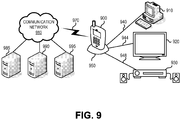
- Figure 1 shows a host mobile device 100 (host), such as a mobile phone, connected to an accessory device (accessory) 150 by a physical connection 140 (e.g., a multi-wire cable).
- the accessory 150 can be, for example, a personal computer 110, a television 120, an audio player 130 or a mobile device.
- the physical connection 140 connects a host connector 160 to an accessory connector 115, 125 or 135 integrated into an accessory 110, 120 or 130.
- the connectors 160, 115, 125 and 135 generally are either male or female and include a grouping of two or more physical pins.
- the connection 140 can support a wide range of connectors, communication interfaces, protocols, features and functions.
- connection 140 can comprise USB (Universal Serial Bus), HDMI (High Definition Multimedia Interface), PCI-Express, DisplayPort, MHL (Mobile High-Definition Link), SATA (Serial ATA) and/or SPDIF (Sony/Philips Digital Interface) connections.
- the connection 140 can also support mass storage, CD/DVD-ROM, web-cam and HID (Human Interface Device) devices or an FM transmitter.
- the connection 140 can be as simple as a stereo cable with a built-in FM antenna.
- the connection 140 can support one or more of these connections, interfaces, features or functions operating concurrently.
- the connection 140 can simultaneously support both USB 3.0 and HDMI, with separate cables or a single cable providing the physical USB and HDMI connections.
- connection 140 can support additional protocols such as 5.1 audio or Ethernet via tunneling over one or more supported protocols, such as USB or PCI-Express.
- functions such as 5.1 audio or Ethernet via tunneling over one or more supported protocols, such as USB or PCI-Express.
- functions such as 5.1 audio or Ethernet via tunneling over one or more supported protocols, such as USB or PCI-Express.
- features such as 5.1 audio or Ethernet
- interface such as USB or PCI-Express
- connector may be used interchangeably and refer to any feature, function, interface, connection, connector, etc. supported by a connection between a host device 100 and an accessory device 150.
- the host device 100 can be any type of general computing or mobile device such as a personal computer, media player or personal digital assistant.
- the host device can be handheld or mobile but the connector described herein can also be used on devices that are typically not handheld or mobile, such as a desktop computer.
- An accessory 150 can be any device capable of physically connecting to and being electronically coupled with the host device 100.
- the accessory personal computer 110, television 120 and audio player 130 can be a set of headphones, a microphone, an FM antenna or other device.
- the terms "host” and "accessory” as used herein indicate a master-slave relationship between connected devices with respect to the discovery of a function set supported by an accessory connector and configuring the capabilities of the host and accessory connectors.
- the host device is typically the master device.
- the host device requests information from the accessory device, selects the connector functions to be enabled, and instructs the accessory device to enable the selected connector functions.
- the accessory device is typically the slave device.
- the accessory device sends requested information to the host device and configures accessory connector functions in response to instructions received from the host device.
- a peer-to-peer relationship can be implemented between the host and the accessory.
- the host 100 can be connected to a communication network 180 via a communication link 170.
- the communication link 170 can be a wired or wireless link.
- the communication network 180 can be a personal area network (PAN), local area network (LAN), the Internet, a cellular or satellite mobile communication network, or any other communication network.
- PAN personal area network
- LAN local area network
- the Internet a cellular or satellite mobile communication network
- the communication configuration shown in Figure 1 allows users to perform a wide variety of operations.
- the host device 100 can download or stream media files (audio, video, etc.) provided by servers 185, 190 and 195 for output at an accessory device 150.
- the host 100 can download or upload information to the personal computer 110 to synchronize the host 100 with information stored on the computer 110.
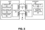
- FIG. 2 is a block diagram of an exemplary host 200 connected to an exemplary accessory 250 via a cable, shown generally at 202.
- the host 200 and accessory 250 can be connected by coupling of a host connector 220 and an accessory connector 270. Such couplings can be releasably attachable, such as through cable connections or mating female-/male-type connectors.
- the host 200 can comprise a controller 210, the host connector 220 and a host connector function store 230.
- the controller can be any microprocessor or microcontroller, as is known in the art.
- the host 200 can also comprise a media store 240.
- the host connector 220 can comprise M fixed-function pins 224 and N multi-function pins 228 where M and N are any integer numbers depending on the particular application.
- Each of the fixed-function pins 224 can have a dedicated function, such as providing a power or ground connection or hosting the function of a pin of a USB port.
- the functions supported by the fixed-function pins typically are not changed during operation of the host device. That is, the fixed-function pins are not configurable.
- Each of the multi-function pins 228 can be configurable and can support more than one function. For example, a multi-function pin can operate as a USB pin in a first configuration, an HDMI pin in a second configuration, and a DisplayPort pin in a third configuration.
- the host controller 210 can be coupled to the host connector 220, the host connector function store 230 and the media store 240.
- the host connector function store 230 stores one or more functions supported by the host connector.
- the function store 230 stores a plurality of possible pin configurations that can be dynamically applied to the connector 220 for on the fly pin configurations.
- the host controller 210 can reference the host connector function store 230 when determining which host connector and accessory connector functions to enable.
- a function can specify, for example, an interface supported by the host connector (HDMI, DisplayPort, PCI-Express, etc.) and can include a mapping of connector pins to interface pins.
- the host connector function store 230 and the media store 240 can be memory, such as volatile memory (e.g., registers, cache, RAM), non-volatile memory (e.g., ROM, FPGA, EEPROM, flash memory, etc.) or some combination of the two.
- volatile memory e.g., registers, cache, RAM
- non-volatile memory e.g., ROM, FPGA, EEPROM, flash memory, etc.
- the accessory device 250 comprises a controller 260, a connector 270 and an accessory connector function store 280.
- the accessory connector 270 can comprise M fixed-function pins 274 and N multi-function pins 278.
- the host connector fixed-function pins 224 can be connected to the accessory connector fixed-function pins 274, and the host connector multi-function pins 228 can be connected to the accessory connector multi-function pins 278.
- the pins of the host connector 220 can be arranged such that the fixed-function pins 224 and the multi-function pins 228 are physically interspersed among each other.
- the fixed-function pins 224 can be physically arranged to be separate from the multi-function pins 228.
- the pins 274 and 278 of the accessory connector 270 can be similarly arranged.
- the host and accessory connectors 220 and 270 can comprise one or more physical ports or connectors.
- the host connector 220 can comprise a micro-USB port comprising a set of fixed-function pins and a second port comprising the remainder of the fixed-functions pins and the multi-function pins.
- a connector can comprise a single physical port that includes all of the connector pins.
- the accessory controller 260 can be connected to the accessory connector 270 and the accessory connector function store 280.
- the accessory connector function store 280 can store functions supported by the accessory connector in a manner similar to that described above in regard to the functions stored in the host connector function store 230.
- any of the host or accessory devices described herein can comprise more than one connector.
- a pass through accessory can be implemented with both a male and female connector.
- host 200 can comprise multiple connectors 220, allowing the host 200 to simultaneously connect to multiple accessories 250.
- the host controller 210 can be connected to each of the host connectors.
- a host device connected to multiple accessory devices via dynamically configurable connectors a mobile phone host device can connect to an external speaker system and a personal computer.
- accessory 250 can comprise multiple connectors 270 to allow connection to multiple hosts 200.
- an accessory television can be connected to multiple host mobile phones.
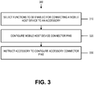
- Figure 3 is a flowchart of a first embodiment 300 of an exemplary method of configuring a mobile host device for connecting to an accessory.
- the host connector can be dynamically configured in response to an accessory being attached to the host device, operations or transactions that are being performed or scheduled to be performed, etc.
- the method 300 could be executed in response to a mobile player being releasably attached to a television.
- the mobile host device can select connector functions to be enabled for connecting a mobile host device to an accessory.
- Information regarding the accessory connector functions can be received from the accessory or another source, and can be stored at the host device. Such information can be communicated via the fixed pins. Additionally, such information can be received in response to a request from the host device.
- the mobile host device can configure pins of the mobile host device connector.
- configuring the pins can comprise assigning each pin to be configured a pin function associated with one of the selected connector functions.
- configuring the pins can comprise assigning individual host device connector pins to support the DATA-, DATA+, VCC and VDD pin functions of the USB interface.
- Configuration of the pins can be static (i.e., the pin configuration for a given function can be determined during host and accessory device design and implemented during device manufacture) or the pin configuration can be dynamic.
- a first multi-function pin can support the DATA- pin function and a second multi-function pin can support the DATA+ pin function in a pin configuration supporting USB.
- Connector pin configuration can comprise the host device enabling the selected connector functions.
- the host connector Prior to 320, the host connector can be unconfigured or previously configured. An unconfigured connector can have one or more connector functions disabled or a set of default functions enabled. Pins that are not enabled in a particular configuration can be kept in a high impedance state until configured. Hardware for putting pins into high-impedance mode is well known in the art, such as tri-state gates.
- enabling the selected connector functions comprises, for each of the pins to be configured, configuring the host device such that one of a plurality of host device pin controllers (discussed below in regards to Figure 4 ) controls (i.e., transmits and receives signals from) the pin.
- the host device such that one of a plurality of host device pin controllers (discussed below in regards to Figure 4 ) controls (i.e., transmits and receives signals from) the pin.
- the host mobile phone can be configured such that the HDMI DDC DAT pin controller controls pin 13.
- the HDMI DDC DAT pin controller can be enabled and the PCIEX CLK+ pin controller can be disabled, or, if the pin controllers are connected to pin 13 by a switch, the switch can be configured to connect the HDMI DDC DAT controller to pin 13.
- the drivers can be loaded from the host device store 230, or downloaded from a remote resource connected to the host device over a network.
- the host device can then inform applications and other devices connected to the host device that the enabled functions are available for use.
- the host device can then begin appropriate communications over the host-accessory connection using the enabled connection functions.
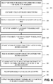
- the method 300 can further comprise authentication of an accessory.
- a host device can send an authentication request to the accessory device.
- the accessory can provide authentication information to the host.
- the accessory device can send its device class (audio, video, mass storage, human interface device, etc.) and sub-class to the host device, along with a digital certificate and/or other authentication information.
- a root certificate is either an unsigned public key certificate or a self-signed certificate that identifies the Root Certificate Authority (CA).
- a root certificate is thus part of a public key infrastructure (PKI) scheme.
- PKI public key infrastructure
- the most common commercial variety is based on the ITU-T X.509 standard, which normally includes a digital signature from a certificate authority (CA).
- Other certificate-based authentication schemes can be used.
- Non-PKI-based solutions such as symmetric key (e.g., shared secret) can be used for authentication.
- the host device can attempt to authenticate the accessory device based on the received information. If the host device can authenticate the accessory, the host device can configure the accessory connector. That is, the accessory can enable a set of accessory connector functions in response to receiving a "function set" instruction from the host.
- the host can request authentication information from accessories having configurable connectors, such as personal computers and mobile devices. Authentication may not be required for certain classes of accessories, depending on the accessories' supported feature set. Authentication can occur over the control channel of the host-accessory connector.
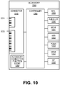
- FIG 4 is a block diagram of an exemplary host device 400 showing several fixed and multi-function pins 426 capable of being controlled by pin controllers 412-419 and 421.
- the host 400 comprises a controller 410, a connector 420, a host connector function store 430 and a media store 440.
- the connector 420 comprises 34 pins physically arranged in two different groups.
- the first group of pins 426 comprises 29 pins (pins 1 through 29) and contains a combination of fixed-function and multi-function pins.
- the second group of pins 422 comprises five fixed-function pins (pins 30-34) which can be compatible with the micro-USB specification published by the USB Implementers Form (available at http://www.usb.org/).
- select pins within the first group of pins 426 can be used to discover the functions supported by an accessory connector connected to the host 400.
- pins 10 and 12 controlled by USB controller 421 can be used to send a request to a connected accessory for the functions supported by the accessory connector and to receive the response from the accessory.
- any other low pin count serial interface such as RS-232 can be used for this functionality.
- the second group of pins 422 can also be used for monitoring or managing the performance of an accessory device. The received accessory connector functions can be passed from the second group of pins 426 to the controller 410.
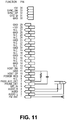
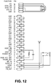
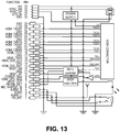
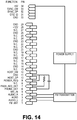
- Figures 11-14 show schematic drawings of exemplary accessories connected to the 39-pin host connector of Figure 4 .
- Figure 11 shows a simple stereo cable with a built-in FM antenna (pin 1) as an accessory.
- Figure 12 shows a passive dock accessory device with stereo analog audio output (pins 2 and 4). The accessory in Figure 12 can be synchronized with the host via the SYNC_DM and SYNC_DP pins and can be powered by the host via pin 34.
- Figure 13 shows an active dock accessory with HDMI and optical SPDIF output capabilities.
- Figure 14 shows an FM transmitter accessory powered by the host via pin 34.
- the host and accessory devices can be components of a single, larger electronic device.
- the host and accessory devices can be integrated circuits within an electronic device.
- the described methods can be used to dynamically configure the pins of host and accessory connectors connected by a bus internal to the single, larger electronic device.
- the accessory device can take a more active role in determining which connection functions are enabled, in addition to sending a list of accessory device connector functions to the host device.
- the accessory device can send accessory device information to the host device that includes information in addition to the functions supported by the accessory connector.
- the accessory device information can include information regarding the power consumption of the accessory device.
- Accessory device power consumption information can include the amount of power consumed by each function supported by the accessory connector or power consumption information of the accessory device as a whole. Current, anticipated and/or historic power consumption data can be supplied.
- the power consumption data can be in the form of average, peak, or root-mean-square power consumed.
- the accessory device information can also include application information such as what applications the accessory device is currently executing, what applications are scheduled to be executed on the accessory device, and what applications are stored at or accessible to the accessory device for execution on the accessory device.
- the accessory device information can include various other types of information such as the clock speeds of the accessory device and the throughput capabilities of each supported accessory connection function.
- the host device can use any of this accessory device information in determining which connector functions to enable. For example, the host device can take into account accessory device power constraints due to the accessory device battery level, the applications currently running on the accessory device, or the maximum amount of power available to the accessory device depending on its power connection. Thus, an accessory device running one or more applications that consume greater amounts of power can limit which functions are to be enabled in a host-accessory connection.
- the accessory device can implement policies to ensure that a host-accessory connection can be configured to support one or more selected accessory connections. For example, if the current operating conditions of the accessory leave too little accessory device to power one or more accessory connection functions, the accessory device can take actions to make the necessary power available. For example, the accessory device can reduce the operating frequency of one or more clocks of the accessory device or stop the execution of applications running on the accessory device.
- Accessory device information can also include processing information.
- the accessory device information can include processing capacities or limitations of the accessory device.
- the accessory device can select a subset of the accessory device connector functions for sending to the host device, based on the accessory device information. For example, if the accessory device is running on battery power, the accessory device can select functions for sending to the host device that consume less power relative to other supported connection functions. In other embodiments, the accessory device can exclude connection functions that would exceed the accessory power budget, if enabled. In some embodiments, the accessory device can place conditions on the functions sent to host device. For example, if the power consumption of an accessory connector function fits within accessory device power constraints if the function is operated at or below a specific frequency, the accessory device can include this frequency in the accessory device information sent to the host device.
- the accessory device can receive host device information from the host device as well.
- the accessory device can use the received host device information when selecting which accessory connection functions are to be sent to the host device.
- the host device information can include a request by the host device to be powered by the accessory device through the host-accessory connection and can include the amount of power requested of the accessory device.
- the accessory device can either accept or deny the host device request for power, and, if accepted, can additionally select connection functions for sending to the host device, that, if enabled, do not exceed the accessory device power constraints if the accessory device provides power to the host device.
- the host device information can include the amount of power that the host device can supply to the accessory device.
- bus arbitration the selection of which functions are to be supported by a host-accessory connection, can include the exchange of messages between the host and accessory devices.
- the host device can send a request to the accessory device for accessory device information.
- the host device can send host device information in addition to this request, such as a request for power from the accessory device.
- the accessory device information sent to the host device can include an indication of one or more functions that can be supported by the accessory device. All, or a subset of all of the functions supported by the accessory device can be included in this indication.
- the accessory device information can include additional accessory device information such as power consumption information, power configuration information, application information and the like.
- the accessory device can select which connection functions are to be sent to the host device based on the accessory device information and/or the received host device information.
- the host device can select one or more functions to be enabled at the host and accessory devices, or make other decisions, based on the received accessory device information. For example, if the host device has requested to be powered by the accessory device, and the accessory device information indicates that the accessory device is running off a battery that is near depletion, the host device can cancel its request.
- the host device can base this selection on additional information about the host device similar to the accessory device information described above (e.g., host device power consumption information, power configuration information, host device application information, etc.).
- a host-accessory connection can be configured depending on the current operating conditions of the host and accessory devices. As discussed in greater detail below, the exchange of information between host and accessory devices can occur upon connection of an accessory device to a host device, at a later point in time such as prior to a new connection function being enabled, or at both times.
- configuration of the host-accessory connection can be based on, and operation of the accessory device can conform to, various licensing policies.
- an accessory device can require that a connected host device have the necessary license before allowing an accessory connector function to be enabled or an accessory device resource to be accessed.
- a high-end printer accessory device can require a host device to have a license before allowing the host device to print documents to the printer.
- a pay-for-use licensing model can be employed in which a user of a host device purchases a license in order to gain access to the accessory device functions or resources using the host device.
- a license can provide a host device with access to media content stored at or accessible by an accessory device.
- a tiered licensing approach can be used in which a host device can gain greater access to media content through purchase of a more expensive license.
- a premium license can provide a host device user with unlimited access to media accessible to the accessory device.
- a host device license can take various forms. For example, a user of a host device connected to an accessory can purchase or upgrade a license while the host device is connected to the accessory device. Alternatively, a host device license can be purchased through connection of the host device to an on-line service associated with an accessory device through a connection to a cloud, described below. The purchase of the license can result in the generation of a token for storage at the host device.
- the token can indicate the terms of a license such as which accessory device functions and/or resources the license provides access to or how much of an accessory resource the host device can consume (e.g., number of pages that can be printed, gigabytes of data that can be transferred, number of songs that can be downloaded).
- a host device license token allows a host device to gain access to accessory device resources and functions when the host device is connected to the accessory device. Host device licensing information, including token information, can be included as part of the host device information described earlier that is sent to the accessory device.
- the accessory and/or host devices can determine or receive an indication when a license has expired or has been revoked.
- a license can expire because, for example, a specified number of pages have been printed, or a subscription period has ended.
- a license can be revoked because, for example, a cloned accessory or host device may no longer be considered a genuine or authentic device. If the license allowed enablement of a connector function, upon expiration of the license, the host device can reconfigure the host connector pins to disable the previously licensed function and instruct the accessory device to disable the same function at the accessory device connector. Alternatively, the accessory device can disable connector functions associated with an expired license without being instructed to do so by a host device.
- the accessory and/or host devices can also determine or receive an indication when a new host device license is available, an expired license has been renewed or an existing license has been upgraded. For example, in response to an accessory device determining that an expired host device license has been renewed, the accessory device can send an indication to the host device that a connector function associated with the renewed license is available. The host device can enable this connector function at the host connector and instruct the accessory device to enable the same function at the accessory device connector. In some embodiments, the accessory device can enable accessory device connector functions associated with a renewed license without being instructed to do so by the host device.
- Figure 17 is a flowchart of additional operations 1700 that can be performed as part of the flowchart shown in Figure 15 for operating a host-accessory connection in conformance with host device licenses and disabling connector functions in response to expiration of a license.
- the additional operations 1700 can be performed by a host mobile phone licensed to access media from an accessory media player.
- the one or more functions enabled at the host-accessory connection can be operated in conformance with one or more host device licenses.
- an HDMI bus can be operated to transfer data at a data rate no greater than that allowed by the host device license.
- the expiration of at least one of the one or more host device licenses can be determined or an indication thereof can be received.
- the host mobile phone can determine that the license has expired due to the expiration of the licensing period or an allowed number of gigabytes have been transferred.
- at least one of the enabled one or more functions at the host device connector can be disabled in response to the determining or receiving an indication that at least one of the one or more host device licenses has expired.
- the host device can disable the HDMI interface at the connector to the accessory media player connector in response to determining that the license allowing access to the media player has expired.
- an accessory speaker system can check whether a docked host mobile phone is an authenticated device before allowing songs stored on the mobile phone to be played on the speaker system.
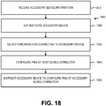
- Figure 18 is a flowchart of an exemplary method of configuring a mobile host device connector for connecting an accessory device connector including authenticating the accessory device.
- the method 1800 can be executed by, for example, a host mobile phone device connecting to an accessory media player.
- accessory device information such as that the media player supports HDMI and PCI-Express interfaces, can be received at the host device.
- the accessory device can be authenticated.
- the host device can select one or more functions to be enabled for connecting the host device to the accessory device. This selection can be based in part on the received accessory device information and whether or not the accessory device has been authenticated. For example, the mobile phone can select HDMI to be enabled at the host connector, and only if the accessory device is an authenticated device.
- one or more pins of the mobile host device connector can be configured.
- the configuring comprises enabling the one or more functions at the mobile host device connector.
- the host mobile phone can enable HDMI at the mobile phone connector.
- the accessory device can be instructed to configure one or more pins of the accessory device connector to support the one or more selected functions.
- the mobile host phone can instruct the accessory device to configure the accessory device connector to support HDMI.
- the host-accessory connection can be encrypted to enable a secure connection.
- the host device can be a first security endpoint with a second security endpoint comprising an accessory device or a docking station (i.e., docking station 950 in Figure 9 ) capable of connecting to one or more accessory devices.
- the encryption can be provided using transport layer security (TLS) or other cryptographic protocols known in the art.
- TLS transport layer security
- a host-accessory device or host-docking station pair can support the secure exchange of cryptographic keys for encryption and decryption of any of the buses enabled in a connection.
- the host device can send an EnumerateFeature request to the accessory device.
- This request can contain the version of the host device software protocol embodying one or more of the methods described herein and can include both the major and minor versions of the protocol. If the accessory device does not support the version of the software protocol indicated in the EnumerateFeature request, the accessory can return an error to the host device. If the host software protocol version is supported, the accessory supplies accessory device information to the host device.
- accessory device information can comprise accessory power consumption information, power configuration information, application information, processing capacity information, accessory device connector functions, and the like.
- the accessory device information can indicate which functions are supported by the accessory connector (e.g., USB 2.0, USB 3.0, PCI-Express, HDMI), which accessory connector pins support each function and which functions can be operated concurrently.
- the accessory device information can also include the accessory device software protocol version, including both major and minor versions. The minor version can be used to identify accessory devices and functions that are backwards compatible with the host device if entire host and accessory device protocol versions are not identical.
- the accessory device information can further include the authentication version, an accessory device unique identifier (e.g., the accessory device globally unique identifier), and accessory device class and sub-class.
- the accessory device can provide some accessory device information in response to the "enumerate features" request, with additional accessory device information supplied at a later time.
- the accessory device can send information about a supported function to the host just prior to the function being enabled by the accessory device.
- the host device After receiving the accessory device's response to the EnumerateFeature request, the host device can determine which connector functions to enable and which pins are to be associated with those functions. The host device can send an instruction to the accessory which connector functions to enable and which functions should be enabled by which pins. In response, the accessory device can enable the pin and function combination as instructed by the host device. The accessory device can also configure any related hardware or software needed to enable traffic across the host-accessory connector. The accessory device can then send an acknowledgment to the host device that the requested functions have been enabled at the requested pins, and that the accessory device is ready to receive communication at the enabled pins. The host device can then enable the selected functions at the selected pins of the host device connector and load the appropriate software drivers for the specified functions. Applications and other resources executing on the host and accessory devices can then be notified that the enabled connector functions are available for use.
- an accessory device can be removed from a host device.
- a Remove Accessory scenario can be initiated by software, hardware or by surprise.
- the host device operating system or other software executing on the host device, can initiate the removal process.
- the host device operating system can decide to initiate the removal process on its own or in response to input received from a user of the host device.
- the accessory can have a button or other input, that, when pressed, generates a removal request that can be sent to the host device.
- the physical connection between host and accessory devices can be broken without notice to the host device. For example, a user can simply remove a host device from a docking station or disconnect cable connecting the host device to an accessory.
- the Remove Accessory scenario can perform the following.
- the host device can issue appropriate notifications to host device applications communicating with the accessory device. Once these host device applications have completed executing, the host can stop the software device drivers and corresponding bus protocol stacks. If the removal was initiated by surprise, the Remove Accessory scenario can be completed at this point.
- the host device informs the accessory device that the host accessory device can be removed.
- the accessory device can then perform the necessary hardware and software actions to stop the software protocol stacks and hardware buses corresponding to the enabled accessory connector functions.
- the accessory can then inform the host device that the accessory has powered down the respective buses and that the host device can notify a user of the host device that it is safe to disconnect the host device from the accessory device.
- the host device can send a PowerOff instruction to the accessory device and notify the user that it is safe to disconnect the host device from the accessory.
- host and accessory connectors can be reconfigured to enable different connector functions or to map enabled functions to different pins.
- Resource reallocation can be performed several different ways. If a full Remove Accessory or Insert Accessory scenario is initiated, the host device can choose a different pin mapping or set of connector functions to be enabled at the host connector. In a partial remove sequence, the host device can stop the specified connector functions and no connector reconfiguration is performed. In this situation, the host device issues the appropriate software notifications to host device applications communicating with the accessory device. Once these host device applications have completed executing, the host can stop the software device drivers and corresponding bus protocol stacks. The host operating system can then inform the accessory device indicating which connector functions and/or pins are to be disabled. The accessory device can then perform the necessary hardware and software actions to stop the software protocol stacks and hardware buses on the appropriate pins, and can send a return message to the host device indicating that the indicated connection functions and pins have been powered down.
- the host device can inform the accessory device which accessory connection functions to enable, and which accessory pins are to enable these functions.
- the accessory device can then enable the specified pin / connector function combinations and configure any related hardware or software needed to enable signal traffic across the enabled pins.
- the accessory device can communicate to the host that the specified connector functions and pins are enabled and that the accessory device is ready to receive appropriate signaling over the enabled buses and pins.
- the host device can then enable the same connector functions at corresponding pins on the host device connector, and load the appropriate software drivers.
- the host device can then begin communication on the enabled pins using the enabled connector functions.
- Host device application can then be notified that the enabled connector functions are available for use.
- the Power Management Scenario applies to the control channel of the host-accessory connection.
- Connector functions e.g., USB, PCI-Express
- Power Management scenarios can be hardware or software initiated.
- the host device operating system or other software initiates the power state transition.
- the host device software can decide to transition to another power state on its own, or based on user input.
- the host device can determine that there has been no activity on the host-accessory connection for a pre-determined or user-specified period, and decide to place the host device is a suspended state (sleep, hibernation, standby) or to power off the host device.
- the host device can send a PowerActive, PowerSuspend or PowerOff instruction to the accessory device.
- the accessory device can power down, and ensure that the present connector configuration (e.g., enabled accessory connector functions, which pins are mapped to the enabled connector functions) is not lost.
- This configuration can be stored at the accessory device or at a resource accessible to the accessory device.
- the accessory device can power down to a low-power state, but continue operation at a power level sufficient to enable a quick resumption of full operation.
- a PowerOff request can cause the accessory device to cut off power to the accessory.
- the scenarios described above use the control channel of the host-accessory connection, although other channels or connector functions can be used to execute the above scenarios.
- the above scenarios including additional scenarios such as device enumeration, start device and stop device scenarios can be handled by the specific mechanisms available to each controller function.
- that USB channel can handle the enumerate device and other scenarios.
- the dynamically configurable host and accessory connectors described herein provide a low pin count connector able to support a wide variety of communication interfaces at the system level.
- the pin count of a host connector comprising multi-function pins can likely be less than that of a connector comprised entirely of dedicated, fixed-function pins.
- the connectors as described herein can accommodate the evolving communication capabilities of host and accessory devices. For example, a host connector can be reconfigured as new accessories implement the various interfaces supported by the connector.
- the host connector can be integrated into host and accessory devices capable of supporting new functions added to existing protocols or entirely new protocols.
- the connector as described herein is flexible and expandable, is forward and backward compatible to allow older devices to communicate with newer ones, and is less likely to require physical modification as communication interfaces continue to evolve.
- the illustrated mobile device 1900 can include a controller or processor 1910 (e.g., signal processor, microprocessor, ASIC, or other control and processing logic circuitry) for performing such tasks as signal coding, data processing, input/output processing, power control, and/or other functions.
- An operating system 1912 can control the allocation and usage of the components 1902 and support for one or more application programs 1914.
- the application programs can include common mobile computing applications (e.g., email applications, calendars, contact managers, web browsers, messaging applications), or any other computing application.
- the illustrated mobile device 1900 can include memory 1920.
- Memory 1920 can include non-removable memory 1922 and/or removable memory 1924.
- the non-removable memory 1922 can include RAM, ROM, flash memory, a hard disk, or other well-known memory storage technologies.
- the removable memory 1924 can include flash memory or a Subscriber Identity Module (SIM) card, which is well known in GSM communication systems, or other well-known memory storage technologies, such as "smart cards.”
- SIM Subscriber Identity Module
- the memory 1920 can be used for storing data and/or code for running the operating system 1912 and the applications 1914.
- Example data can include web pages, text, images, sound files, video data or other data sets to be sent to and/or received from one or more network servers or other devices via one or more wired or wireless networks.
- the memory 1920 can be used to store a subscriber identifier, such as an International Mobile Subscriber Identity (IMSI), and an equipment identifier, such as an International Mobile Equipment Identifier (IMEI). Such identifiers can be transmitted to a network server to identify users and equipment.
- IMSI International Mobile Subscriber Identity
- IMEI International Mobile Equipment Identifier
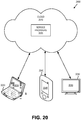
- Figure 20 illustrates a generalized example of a suitable implementation environment 2000 in which described embodiments, techniques, and technologies may be implemented.
- various types of services can be provided by a cloud 2010.
- the cloud 2010 can comprise a collection of computing devices, which may be located centrally, or distributed, that provide cloud-based services to various types of users and devices connected via a network such as the Internet.
- the implementation environment 2000 can be used in different ways to accomplish computing tasks. For example, some tasks (e.g., processing user input and presenting a user interface) can be performed on local computing devices (e.g., connected devices 2030, 2040, 2050) while other tasks (e.g., storage of data to be used in subsequent processing) can be performed in the cloud 2010.
- Services can be provided by the cloud 2010 through service providers 2020, or through other providers of online services (not depicted).
- cloud services can be customized to the screen size, display capability, and/or touch screen capability of a particular connected device (e.g., connected devices 2030, 2040, 2050).
- connection of a mobile phone to a car dock can invoke a host device user interface indicating nearby dealers or mechanics capable of serving the specific car make and model if car diagnostic applications executing on the accessory device communicate to the host device that the car is in need of service.
- the accessory device can store accessory-specific metadata.
- an accessory device can store information indicating the accessory category, type, class, subclass or the like.
- the metadata can also include information related to capabilities of the accessory.
- Any of the disclosed methods can be implemented as computer-executable instructions stored on one or more computer-readable storage media (e.g., non-transitory computer-readable media, such as one or more optical media discs, volatile memory components (such as DRAM or SRAM), or nonvolatile memory components (such as hard drives)) and executed on a computer (e.g., any commercially available computer, including smart phones or other mobile devices that include computing hardware).
- a computer e.g., any commercially available computer, including smart phones or other mobile devices that include computing hardware.
- Any of the computer-executable instructions for implementing the disclosed techniques as well as any data created and used during implementation of the disclosed embodiments can be stored on one or more computer-readable media (e.g., non-transitory computer-readable media).
Landscapes
- Engineering & Computer Science (AREA)
- Theoretical Computer Science (AREA)
- General Engineering & Computer Science (AREA)
- Physics & Mathematics (AREA)
- General Physics & Mathematics (AREA)
- Computer Hardware Design (AREA)
- Telephone Set Structure (AREA)
- Telephone Function (AREA)
- Two-Way Televisions, Distribution Of Moving Picture Or The Like (AREA)
- Computer And Data Communications (AREA)
- Power Sources (AREA)
- Details Of Connecting Devices For Male And Female Coupling (AREA)
Applications Claiming Priority (3)
| Application Number | Priority Date | Filing Date | Title |
|---|---|---|---|
| US32423610P | 2010-04-14 | 2010-04-14 | |
| US12/826,551 US8504823B2 (en) | 2009-11-24 | 2010-06-29 | Dynamic configuration of connectors for system-level communications |
| PCT/US2011/031033 WO2011130026A2 (en) | 2010-04-14 | 2011-04-04 | Dynamic configuration of connectors for system level communications |
Publications (3)
| Publication Number | Publication Date |
|---|---|
| EP2559225A2 EP2559225A2 (en) | 2013-02-20 |
| EP2559225A4 EP2559225A4 (en) | 2013-07-24 |
| EP2559225B1 true EP2559225B1 (en) | 2017-02-15 |
Family
ID=44799246
Family Applications (1)
| Application Number | Title | Priority Date | Filing Date |
|---|---|---|---|
| EP11769290.5A Not-in-force EP2559225B1 (en) | 2010-04-14 | 2011-04-04 | Dynamic configuration of connectors for system level communications |
Country Status (8)
| Country | Link |
|---|---|
| EP (1) | EP2559225B1 (enExample) |
| JP (1) | JP5856146B2 (enExample) |
| KR (1) | KR101854929B1 (enExample) |
| CN (1) | CN102845046B (enExample) |
| AU (1) | AU2011240960B2 (enExample) |
| CA (1) | CA2793617C (enExample) |
| IL (1) | IL222005A (enExample) |
| WO (1) | WO2011130026A2 (enExample) |
Families Citing this family (27)
| Publication number | Priority date | Publication date | Assignee | Title |
|---|---|---|---|---|
| CN102546584B (zh) * | 2010-11-01 | 2015-05-27 | 微软公司 | 附件特定的用户体验的调用 |
| CA2759736C (en) * | 2010-11-30 | 2020-12-29 | Printeron Inc. | System for internet enabled printing |
| MY169836A (en) | 2011-12-06 | 2019-05-16 | Intel Corp | Techniques for serial interface charging |
| EP2711843B1 (en) * | 2012-09-21 | 2016-04-06 | Nxp B.V. | DisplayPort over USB mechanical interface |
| CN106062573B (zh) * | 2014-03-13 | 2020-02-28 | 高准公司 | 用于重新配置连接器上的管脚分配的方法和装置 |
| CN104950987B (zh) * | 2014-03-24 | 2019-07-26 | 环旭电子股份有限公司 | 扩充座 |
| JP6312842B2 (ja) * | 2015-08-14 | 2018-04-18 | エスゼット ディージェイアイ テクノロジー カンパニー リミテッドSz Dji Technology Co.,Ltd | 異機種環境においてデータ通信を支援するためのシステム及び方法、並びにプログラム |
| US10455375B2 (en) * | 2015-11-21 | 2019-10-22 | Nanoport Technology Inc. | Controlling access to a hardware resource of an electronic device by a magnetically attachable electronic device |
| US10289584B2 (en) | 2016-01-06 | 2019-05-14 | Toshiba Client Solutions CO., LTD. | Using a standard USB Type-C connector to communicate both USB 3.x and displayport data |
| US10015594B2 (en) | 2016-06-23 | 2018-07-03 | Microsoft Technology Licensing, Llc | Peripheral device transducer configuration |
| CN106099559A (zh) * | 2016-08-26 | 2016-11-09 | 上海芯什达电子技术有限公司 | 一种电子设备 |
| JP6772078B2 (ja) * | 2017-01-16 | 2020-10-21 | キヤノン株式会社 | 撮像装置及びその制御方法、並びに、撮像システム |
| JP6942474B2 (ja) * | 2017-01-16 | 2021-09-29 | キヤノン株式会社 | 撮像装置及びその制御方法、並びに、撮像システム |
| JP6808502B2 (ja) * | 2017-01-16 | 2021-01-06 | キヤノン株式会社 | 撮像装置及びその制御方法、並びに、撮像システム |
| JP6873710B2 (ja) * | 2017-01-16 | 2021-05-19 | キヤノン株式会社 | 撮像装置及びその制御方法、並びに、撮像システム |
| US10769094B2 (en) | 2017-02-01 | 2020-09-08 | Hewlett-Packard Development Company, L.P. | Configuration options for display devices |
| US10509759B2 (en) * | 2017-03-31 | 2019-12-17 | Intel Corporation | Multiple storage devices implemented using a common connector |
| CN109167219B (zh) | 2017-06-15 | 2020-11-03 | 南宁富桂精密工业有限公司 | 连接器及具有该连接器的电子装置 |
| US11170095B2 (en) | 2017-06-28 | 2021-11-09 | GE Precision Healthcare LLC | Catheter authorization system and method |
| US10546146B2 (en) | 2017-06-28 | 2020-01-28 | General Electric Company | Catheter authorization system and method |
| JP7139815B2 (ja) * | 2018-09-19 | 2022-09-21 | 富士フイルムビジネスイノベーション株式会社 | 情報処理装置 |
| CN111048928B (zh) * | 2018-10-12 | 2021-09-17 | 技嘉科技股份有限公司 | 外接式电连接器及电脑系统 |
| TWI704734B (zh) * | 2018-10-12 | 2020-09-11 | 技嘉科技股份有限公司 | 外接式電連接器及電腦系統 |
| CN109766291B (zh) * | 2018-12-06 | 2020-10-23 | 珠海格力电器股份有限公司 | 一种i/o端口的自动配置方法及系统 |
| US10827271B1 (en) * | 2019-10-07 | 2020-11-03 | Synaptics Incorporated | Backward compatibility for audio systems and methods |
| CN114296808B (zh) * | 2021-12-23 | 2022-12-02 | 科东(广州)软件科技有限公司 | 一种引脚配置方法、装置、电子设备及存储介质 |
| CN120832325A (zh) * | 2024-04-16 | 2025-10-24 | 深圳海翼智新科技有限公司 | 设备功能实现方法及装置 |
Family Cites Families (19)
| Publication number | Priority date | Publication date | Assignee | Title |
|---|---|---|---|---|
| US4972470A (en) * | 1987-08-06 | 1990-11-20 | Steven Farago | Programmable connector |
| US6581098B1 (en) * | 1999-09-27 | 2003-06-17 | Hewlett-Packard Development Company, L.P. | Server providing access to a plurality of functions of a multifunction peripheral in a network |
| JP2002007010A (ja) * | 2000-06-26 | 2002-01-11 | Sony Corp | コネクタを備えた電子機器 |
| US7631265B1 (en) * | 2000-12-29 | 2009-12-08 | Gateway, Inc. | System and method for configuring and loading a user interface |
| JP2003241867A (ja) * | 2002-02-18 | 2003-08-29 | Kyocera Corp | 携帯端末、通信ケーブル、及びインタフェース切替方法 |
| US7305254B2 (en) * | 2003-07-17 | 2007-12-04 | Sony Ericsson Mobile Communications Ab | System and method of software transfer between a mobile phone and a mobile phone accessory |
| AU2004300958A1 (en) * | 2003-08-13 | 2005-02-24 | Qualcomm, Incorporated | A signal interface for higher data rates |
| US7424312B2 (en) * | 2003-09-23 | 2008-09-09 | Motorola, Inc. | Interface system for an accessory and a communication device |
| WO2006026443A2 (en) * | 2004-08-27 | 2006-03-09 | Ivan Cardenas | Dynamic physical interface between computer module and computer accessory and methods |
| US7184794B2 (en) * | 2004-09-09 | 2007-02-27 | Motorola, Inc. | Electronic apparatus and system with multi-purpose interface |
| US7512720B2 (en) * | 2005-04-29 | 2009-03-31 | Sigmatel, Inc. | System and method for accessing universal serial bus networks |
| US20070135092A1 (en) * | 2005-12-08 | 2007-06-14 | Pieronek James V | Method and apparatus for authenticating a mobile phone accessory |
| JP4561642B2 (ja) * | 2006-01-26 | 2010-10-13 | 株式会社デンソー | 車両用ダウンロードシステムおよびそれに用いられる車両用端末機 |
| US7769939B2 (en) * | 2006-06-26 | 2010-08-03 | Thomson Licensing | Apparatus and method for interfacing electronic devices |
| US20080152305A1 (en) * | 2006-12-21 | 2008-06-26 | General Instrument Corporation | Portable Media Content Storage and Rendering Device |
| US7836223B2 (en) * | 2007-07-02 | 2010-11-16 | Silicon Image, Inc. | Operation of media interface to provide bidirectional communications |
| JP4492761B2 (ja) * | 2008-06-16 | 2010-06-30 | コニカミノルタホールディングス株式会社 | 画像形成装置および画像形成装置におけるアクセス制御方法 |
| US8208853B2 (en) * | 2008-09-08 | 2012-06-26 | Apple Inc. | Accessory device authentication |
| US7865629B1 (en) * | 2009-11-24 | 2011-01-04 | Microsoft Corporation | Configurable connector for system-level communication |
-
2011
- 2011-04-04 CN CN201180018957.3A patent/CN102845046B/zh not_active Expired - Fee Related
- 2011-04-04 JP JP2013504931A patent/JP5856146B2/ja not_active Expired - Fee Related
- 2011-04-04 WO PCT/US2011/031033 patent/WO2011130026A2/en not_active Ceased
- 2011-04-04 KR KR1020127026792A patent/KR101854929B1/ko not_active Expired - Fee Related
- 2011-04-04 EP EP11769290.5A patent/EP2559225B1/en not_active Not-in-force
- 2011-04-04 AU AU2011240960A patent/AU2011240960B2/en not_active Ceased
- 2011-04-04 CA CA2793617A patent/CA2793617C/en not_active Expired - Fee Related
-
2012
- 2012-09-20 IL IL222005A patent/IL222005A/en not_active IP Right Cessation
Non-Patent Citations (1)
| Title |
|---|
| None * |
Also Published As
| Publication number | Publication date |
|---|---|
| EP2559225A2 (en) | 2013-02-20 |
| CA2793617A1 (en) | 2011-10-20 |
| AU2011240960A1 (en) | 2012-09-27 |
| KR101854929B1 (ko) | 2018-05-04 |
| JP5856146B2 (ja) | 2016-02-09 |
| IL222005A (en) | 2016-03-31 |
| JP2013526149A (ja) | 2013-06-20 |
| KR20130073872A (ko) | 2013-07-03 |
| CN102845046B (zh) | 2015-11-25 |
| EP2559225A4 (en) | 2013-07-24 |
| WO2011130026A3 (en) | 2012-03-08 |
| CA2793617C (en) | 2017-09-05 |
| AU2011240960B2 (en) | 2014-06-12 |
| CN102845046A (zh) | 2012-12-26 |
| WO2011130026A2 (en) | 2011-10-20 |
Similar Documents
| Publication | Publication Date | Title |
|---|---|---|
| EP2559225B1 (en) | Dynamic configuration of connectors for system level communications | |
| US8504823B2 (en) | Dynamic configuration of connectors for system-level communications | |
| US8719112B2 (en) | Invocation of accessory-specific user experience | |
| CN102483728B (zh) | 非对称串行协议的模式之间的取决于设备的选择 | |
| CN103947224B (zh) | 使用无线对接系统配置和控制音频系统的混合器的方法和设备 | |
| KR102231741B1 (ko) | 부속 디바이스 전력 관리 | |
| CN102546584B (zh) | 附件特定的用户体验的调用 | |
| US8438408B2 (en) | Control of accessory components by portable computing device | |
| HK1180127B (en) | Dynamic configuration of connectors for system level communications | |
| HK1180127A (en) | Dynamic configuration of connectors for system level communications | |
| US20260122503A1 (en) | Device pairing using power-based communications | |
| CN118796087A (zh) | 存储扩展方法、电子设备、外部存储设备及存储介质 | |
| HK1176700B (en) | Configurable connector for system-level communication | |
| JP2001109703A (ja) | 電子機器装置における基本入出力制御プログラムを格納した記憶媒体及び基本入出力制御方法 |
Legal Events
| Date | Code | Title | Description |
|---|---|---|---|
| PUAI | Public reference made under article 153(3) epc to a published international application that has entered the european phase |
Free format text: ORIGINAL CODE: 0009012 |
|
| 17P | Request for examination filed |
Effective date: 20120927 |
|
| AK | Designated contracting states |
Kind code of ref document: A2 Designated state(s): AL AT BE BG CH CY CZ DE DK EE ES FI FR GB GR HR HU IE IS IT LI LT LU LV MC MK MT NL NO PL PT RO RS SE SI SK SM TR |
|
| A4 | Supplementary search report drawn up and despatched |
Effective date: 20130626 |
|
| DAX | Request for extension of the european patent (deleted) | ||
| RIC1 | Information provided on ipc code assigned before grant |
Ipc: G06F 13/40 20060101AFI20130620BHEP Ipc: G06F 13/38 20060101ALI20130620BHEP |
|
| REG | Reference to a national code |
Ref country code: HK Ref legal event code: DE Ref document number: 1180127 Country of ref document: HK |
|
| 17Q | First examination report despatched |
Effective date: 20130927 |
|
| RAP1 | Party data changed (applicant data changed or rights of an application transferred) |
Owner name: MICROSOFT TECHNOLOGY LICENSING, LLC |
|
| REG | Reference to a national code |
Ref country code: DE Ref legal event code: R079 Ref document number: 602011035058 Country of ref document: DE Free format text: PREVIOUS MAIN CLASS: H04L0029100000 Ipc: G06F0013400000 |
|
| RIC1 | Information provided on ipc code assigned before grant |
Ipc: G06F 1/26 20060101ALI20160422BHEP Ipc: G06F 13/38 20060101ALI20160422BHEP Ipc: G06F 13/40 20060101AFI20160422BHEP |
|
| GRAP | Despatch of communication of intention to grant a patent |
Free format text: ORIGINAL CODE: EPIDOSNIGR1 |
|
| INTG | Intention to grant announced |
Effective date: 20160603 |
|
| GRAJ | Information related to disapproval of communication of intention to grant by the applicant or resumption of examination proceedings by the epo deleted |
Free format text: ORIGINAL CODE: EPIDOSDIGR1 |
|
| GRAP | Despatch of communication of intention to grant a patent |
Free format text: ORIGINAL CODE: EPIDOSNIGR1 |
|
| INTC | Intention to grant announced (deleted) | ||
| INTG | Intention to grant announced |
Effective date: 20161014 |
|
| GRAS | Grant fee paid |
Free format text: ORIGINAL CODE: EPIDOSNIGR3 |
|
| GRAA | (expected) grant |
Free format text: ORIGINAL CODE: 0009210 |
|
| AK | Designated contracting states |
Kind code of ref document: B1 Designated state(s): AL AT BE BG CH CY CZ DE DK EE ES FI FR GB GR HR HU IE IS IT LI LT LU LV MC MK MT NL NO PL PT RO RS SE SI SK SM TR |
|
| REG | Reference to a national code |
Ref country code: CH Ref legal event code: EP Ref country code: GB Ref legal event code: FG4D |
|
| REG | Reference to a national code |
Ref country code: IE Ref legal event code: FG4D |
|
| REG | Reference to a national code |
Ref country code: FR Ref legal event code: PLFP Year of fee payment: 7 |
|
| REG | Reference to a national code |
Ref country code: AT Ref legal event code: REF Ref document number: 868255 Country of ref document: AT Kind code of ref document: T Effective date: 20170315 |
|
| REG | Reference to a national code |
Ref country code: DE Ref legal event code: R096 Ref document number: 602011035058 Country of ref document: DE |
|
| REG | Reference to a national code |
Ref country code: NL Ref legal event code: FP |
|
| REG | Reference to a national code |
Ref country code: LT Ref legal event code: MG4D |
|
| REG | Reference to a national code |
Ref country code: AT Ref legal event code: MK05 Ref document number: 868255 Country of ref document: AT Kind code of ref document: T Effective date: 20170215 |
|
| PG25 | Lapsed in a contracting state [announced via postgrant information from national office to epo] |
Ref country code: GR Free format text: LAPSE BECAUSE OF FAILURE TO SUBMIT A TRANSLATION OF THE DESCRIPTION OR TO PAY THE FEE WITHIN THE PRESCRIBED TIME-LIMIT Effective date: 20170516 Ref country code: FI Free format text: LAPSE BECAUSE OF FAILURE TO SUBMIT A TRANSLATION OF THE DESCRIPTION OR TO PAY THE FEE WITHIN THE PRESCRIBED TIME-LIMIT Effective date: 20170215 Ref country code: HR Free format text: LAPSE BECAUSE OF FAILURE TO SUBMIT A TRANSLATION OF THE DESCRIPTION OR TO PAY THE FEE WITHIN THE PRESCRIBED TIME-LIMIT Effective date: 20170215 Ref country code: LT Free format text: LAPSE BECAUSE OF FAILURE TO SUBMIT A TRANSLATION OF THE DESCRIPTION OR TO PAY THE FEE WITHIN THE PRESCRIBED TIME-LIMIT Effective date: 20170215 Ref country code: NO Free format text: LAPSE BECAUSE OF FAILURE TO SUBMIT A TRANSLATION OF THE DESCRIPTION OR TO PAY THE FEE WITHIN THE PRESCRIBED TIME-LIMIT Effective date: 20170515 |
|
| PG25 | Lapsed in a contracting state [announced via postgrant information from national office to epo] |
Ref country code: PT Free format text: LAPSE BECAUSE OF FAILURE TO SUBMIT A TRANSLATION OF THE DESCRIPTION OR TO PAY THE FEE WITHIN THE PRESCRIBED TIME-LIMIT Effective date: 20170615 Ref country code: LV Free format text: LAPSE BECAUSE OF FAILURE TO SUBMIT A TRANSLATION OF THE DESCRIPTION OR TO PAY THE FEE WITHIN THE PRESCRIBED TIME-LIMIT Effective date: 20170215 Ref country code: BG Free format text: LAPSE BECAUSE OF FAILURE TO SUBMIT A TRANSLATION OF THE DESCRIPTION OR TO PAY THE FEE WITHIN THE PRESCRIBED TIME-LIMIT Effective date: 20170515 Ref country code: ES Free format text: LAPSE BECAUSE OF FAILURE TO SUBMIT A TRANSLATION OF THE DESCRIPTION OR TO PAY THE FEE WITHIN THE PRESCRIBED TIME-LIMIT Effective date: 20170215 Ref country code: RS Free format text: LAPSE BECAUSE OF FAILURE TO SUBMIT A TRANSLATION OF THE DESCRIPTION OR TO PAY THE FEE WITHIN THE PRESCRIBED TIME-LIMIT Effective date: 20170215 Ref country code: AT Free format text: LAPSE BECAUSE OF FAILURE TO SUBMIT A TRANSLATION OF THE DESCRIPTION OR TO PAY THE FEE WITHIN THE PRESCRIBED TIME-LIMIT Effective date: 20170215 Ref country code: SE Free format text: LAPSE BECAUSE OF FAILURE TO SUBMIT A TRANSLATION OF THE DESCRIPTION OR TO PAY THE FEE WITHIN THE PRESCRIBED TIME-LIMIT Effective date: 20170215 |
|
| PG25 | Lapsed in a contracting state [announced via postgrant information from national office to epo] |
Ref country code: CZ Free format text: LAPSE BECAUSE OF FAILURE TO SUBMIT A TRANSLATION OF THE DESCRIPTION OR TO PAY THE FEE WITHIN THE PRESCRIBED TIME-LIMIT Effective date: 20170215 Ref country code: SK Free format text: LAPSE BECAUSE OF FAILURE TO SUBMIT A TRANSLATION OF THE DESCRIPTION OR TO PAY THE FEE WITHIN THE PRESCRIBED TIME-LIMIT Effective date: 20170215 Ref country code: RO Free format text: LAPSE BECAUSE OF FAILURE TO SUBMIT A TRANSLATION OF THE DESCRIPTION OR TO PAY THE FEE WITHIN THE PRESCRIBED TIME-LIMIT Effective date: 20170215 Ref country code: EE Free format text: LAPSE BECAUSE OF FAILURE TO SUBMIT A TRANSLATION OF THE DESCRIPTION OR TO PAY THE FEE WITHIN THE PRESCRIBED TIME-LIMIT Effective date: 20170215 Ref country code: IT Free format text: LAPSE BECAUSE OF FAILURE TO SUBMIT A TRANSLATION OF THE DESCRIPTION OR TO PAY THE FEE WITHIN THE PRESCRIBED TIME-LIMIT Effective date: 20170215 |
|
| REG | Reference to a national code |
Ref country code: DE Ref legal event code: R097 Ref document number: 602011035058 Country of ref document: DE |
|
| PG25 | Lapsed in a contracting state [announced via postgrant information from national office to epo] |
Ref country code: SM Free format text: LAPSE BECAUSE OF FAILURE TO SUBMIT A TRANSLATION OF THE DESCRIPTION OR TO PAY THE FEE WITHIN THE PRESCRIBED TIME-LIMIT Effective date: 20170215 Ref country code: DK Free format text: LAPSE BECAUSE OF FAILURE TO SUBMIT A TRANSLATION OF THE DESCRIPTION OR TO PAY THE FEE WITHIN THE PRESCRIBED TIME-LIMIT Effective date: 20170215 Ref country code: PL Free format text: LAPSE BECAUSE OF FAILURE TO SUBMIT A TRANSLATION OF THE DESCRIPTION OR TO PAY THE FEE WITHIN THE PRESCRIBED TIME-LIMIT Effective date: 20170215 |
|
| REG | Reference to a national code |
Ref country code: CH Ref legal event code: PL |
|
| REG | Reference to a national code |
Ref country code: HK Ref legal event code: GR Ref document number: 1180127 Country of ref document: HK |
|
| PLBE | No opposition filed within time limit |
Free format text: ORIGINAL CODE: 0009261 |
|
| STAA | Information on the status of an ep patent application or granted ep patent |
Free format text: STATUS: NO OPPOSITION FILED WITHIN TIME LIMIT |
|
| 26N | No opposition filed |
Effective date: 20171116 |
|
| REG | Reference to a national code |
Ref country code: IE Ref legal event code: MM4A |
|
| PG25 | Lapsed in a contracting state [announced via postgrant information from national office to epo] |
Ref country code: MC Free format text: LAPSE BECAUSE OF FAILURE TO SUBMIT A TRANSLATION OF THE DESCRIPTION OR TO PAY THE FEE WITHIN THE PRESCRIBED TIME-LIMIT Effective date: 20170215 |
|
| PG25 | Lapsed in a contracting state [announced via postgrant information from national office to epo] |
Ref country code: CH Free format text: LAPSE BECAUSE OF NON-PAYMENT OF DUE FEES Effective date: 20170430 Ref country code: LI Free format text: LAPSE BECAUSE OF NON-PAYMENT OF DUE FEES Effective date: 20170430 Ref country code: SI Free format text: LAPSE BECAUSE OF FAILURE TO SUBMIT A TRANSLATION OF THE DESCRIPTION OR TO PAY THE FEE WITHIN THE PRESCRIBED TIME-LIMIT Effective date: 20170215 Ref country code: LU Free format text: LAPSE BECAUSE OF NON-PAYMENT OF DUE FEES Effective date: 20170404 |
|
| REG | Reference to a national code |
Ref country code: FR Ref legal event code: PLFP Year of fee payment: 8 |
|
| REG | Reference to a national code |
Ref country code: BE Ref legal event code: MM Effective date: 20170430 |
|
| PG25 | Lapsed in a contracting state [announced via postgrant information from national office to epo] |
Ref country code: IE Free format text: LAPSE BECAUSE OF NON-PAYMENT OF DUE FEES Effective date: 20170404 |
|
| PG25 | Lapsed in a contracting state [announced via postgrant information from national office to epo] |
Ref country code: BE Free format text: LAPSE BECAUSE OF NON-PAYMENT OF DUE FEES Effective date: 20170430 |
|
| PG25 | Lapsed in a contracting state [announced via postgrant information from national office to epo] |
Ref country code: MT Free format text: LAPSE BECAUSE OF NON-PAYMENT OF DUE FEES Effective date: 20170404 |
|
| PG25 | Lapsed in a contracting state [announced via postgrant information from national office to epo] |
Ref country code: HU Free format text: LAPSE BECAUSE OF FAILURE TO SUBMIT A TRANSLATION OF THE DESCRIPTION OR TO PAY THE FEE WITHIN THE PRESCRIBED TIME-LIMIT; INVALID AB INITIO Effective date: 20110404 |
|
| PG25 | Lapsed in a contracting state [announced via postgrant information from national office to epo] |
Ref country code: CY Free format text: LAPSE BECAUSE OF NON-PAYMENT OF DUE FEES Effective date: 20170215 |
|
| PG25 | Lapsed in a contracting state [announced via postgrant information from national office to epo] |
Ref country code: MK Free format text: LAPSE BECAUSE OF FAILURE TO SUBMIT A TRANSLATION OF THE DESCRIPTION OR TO PAY THE FEE WITHIN THE PRESCRIBED TIME-LIMIT Effective date: 20170215 |
|
| REG | Reference to a national code |
Ref country code: DE Ref legal event code: R082 Ref document number: 602011035058 Country of ref document: DE |
|
| PG25 | Lapsed in a contracting state [announced via postgrant information from national office to epo] |
Ref country code: TR Free format text: LAPSE BECAUSE OF FAILURE TO SUBMIT A TRANSLATION OF THE DESCRIPTION OR TO PAY THE FEE WITHIN THE PRESCRIBED TIME-LIMIT Effective date: 20170215 |
|
| PG25 | Lapsed in a contracting state [announced via postgrant information from national office to epo] |
Ref country code: AL Free format text: LAPSE BECAUSE OF FAILURE TO SUBMIT A TRANSLATION OF THE DESCRIPTION OR TO PAY THE FEE WITHIN THE PRESCRIBED TIME-LIMIT Effective date: 20170215 Ref country code: IS Free format text: LAPSE BECAUSE OF FAILURE TO SUBMIT A TRANSLATION OF THE DESCRIPTION OR TO PAY THE FEE WITHIN THE PRESCRIBED TIME-LIMIT Effective date: 20170615 |
|
| P01 | Opt-out of the competence of the unified patent court (upc) registered |
Effective date: 20230501 |
|
| PGFP | Annual fee paid to national office [announced via postgrant information from national office to epo] |
Ref country code: NL Payment date: 20240320 Year of fee payment: 14 |
|
| PGFP | Annual fee paid to national office [announced via postgrant information from national office to epo] |
Ref country code: GB Payment date: 20240320 Year of fee payment: 14 |
|
| PGFP | Annual fee paid to national office [announced via postgrant information from national office to epo] |
Ref country code: FR Payment date: 20240320 Year of fee payment: 14 |
|
| PGFP | Annual fee paid to national office [announced via postgrant information from national office to epo] |
Ref country code: DE Payment date: 20240320 Year of fee payment: 14 |
|
| REG | Reference to a national code |
Ref country code: DE Ref legal event code: R119 Ref document number: 602011035058 Country of ref document: DE |
|
| REG | Reference to a national code |
Ref country code: NL Ref legal event code: MM Effective date: 20250501 |
|
| GBPC | Gb: european patent ceased through non-payment of renewal fee |
Effective date: 20250404 |
|
| PG25 | Lapsed in a contracting state [announced via postgrant information from national office to epo] |
Ref country code: DE Free format text: LAPSE BECAUSE OF NON-PAYMENT OF DUE FEES Effective date: 20251104 |
|
| PG25 | Lapsed in a contracting state [announced via postgrant information from national office to epo] |
Ref country code: GB Free format text: LAPSE BECAUSE OF NON-PAYMENT OF DUE FEES Effective date: 20250404 |
|
| PG25 | Lapsed in a contracting state [announced via postgrant information from national office to epo] |
Ref country code: FR Free format text: LAPSE BECAUSE OF NON-PAYMENT OF DUE FEES Effective date: 20250430 Ref country code: NL Free format text: LAPSE BECAUSE OF NON-PAYMENT OF DUE FEES Effective date: 20250501 |