EP2558736B1 - Douille de spire ayant des créneaux ménages dans une tige annulaire - Google Patents
Douille de spire ayant des créneaux ménages dans une tige annulaire Download PDFInfo
- Publication number
- EP2558736B1 EP2558736B1 EP11714901.3A EP11714901A EP2558736B1 EP 2558736 B1 EP2558736 B1 EP 2558736B1 EP 11714901 A EP11714901 A EP 11714901A EP 2558736 B1 EP2558736 B1 EP 2558736B1
- Authority
- EP
- European Patent Office
- Prior art keywords
- shank
- insert
- ridge
- ridges
- fastener insert
- Prior art date
- Legal status (The legal status is an assumption and is not a legal conclusion. Google has not performed a legal analysis and makes no representation as to the accuracy of the status listed.)
- Not-in-force
Links
- 230000007704 transition Effects 0.000 claims description 4
- 239000000463 material Substances 0.000 description 17
- 229920003023 plastic Polymers 0.000 description 12
- 239000004033 plastic Substances 0.000 description 12
- 238000000034 method Methods 0.000 description 8
- 239000002184 metal Substances 0.000 description 7
- 238000003780 insertion Methods 0.000 description 6
- 230000037431 insertion Effects 0.000 description 6
- 229910000831 Steel Inorganic materials 0.000 description 5
- 239000010959 steel Substances 0.000 description 5
- 229910001369 Brass Inorganic materials 0.000 description 3
- 230000015572 biosynthetic process Effects 0.000 description 3
- 239000010951 brass Substances 0.000 description 3
- 238000005755 formation reaction Methods 0.000 description 3
- 238000009434 installation Methods 0.000 description 3
- 238000005096 rolling process Methods 0.000 description 3
- 238000003754 machining Methods 0.000 description 2
- 238000004519 manufacturing process Methods 0.000 description 2
- 239000012768 molten material Substances 0.000 description 2
- 238000004873 anchoring Methods 0.000 description 1
- 230000000712 assembly Effects 0.000 description 1
- 238000000429 assembly Methods 0.000 description 1
- 238000010276 construction Methods 0.000 description 1
- 239000007788 liquid Substances 0.000 description 1
- 238000010297 mechanical methods and process Methods 0.000 description 1
- 230000005226 mechanical processes and functions Effects 0.000 description 1
- 238000002844 melting Methods 0.000 description 1
- 230000008018 melting Effects 0.000 description 1
- 238000000465 moulding Methods 0.000 description 1
- 230000007935 neutral effect Effects 0.000 description 1
Images

Classifications
-
- F—MECHANICAL ENGINEERING; LIGHTING; HEATING; WEAPONS; BLASTING
- F16—ENGINEERING ELEMENTS AND UNITS; GENERAL MEASURES FOR PRODUCING AND MAINTAINING EFFECTIVE FUNCTIONING OF MACHINES OR INSTALLATIONS; THERMAL INSULATION IN GENERAL
- F16B—DEVICES FOR FASTENING OR SECURING CONSTRUCTIONAL ELEMENTS OR MACHINE PARTS TOGETHER, e.g. NAILS, BOLTS, CIRCLIPS, CLAMPS, CLIPS OR WEDGES; JOINTS OR JOINTING
- F16B37/00—Nuts or like thread-engaging members
- F16B37/12—Nuts or like thread-engaging members with thread-engaging surfaces formed by inserted coil-springs, discs, or the like; Independent pieces of wound wire used as nuts; Threaded inserts for holes
- F16B37/122—Threaded inserts, e.g. "rampa bolts"
Definitions
- the present invention relates generally to fasteners and fastening systems, and, more particularly, to fastener components of fastening systems that are embedded in another part, often of dissimilar material.
- fastening systems that include threaded inserts of metal that are anchored in plastic or other components when used to receive a screw or bolt for holding a second component in an assembly.
- plastic parts in automobiles, computers, appliances of different types, and various other assemblies are known to be provided with metal inserts having internal threads so that another part can be held thereto by a bolt or screw engaged with the insert.
- anchor a threaded stud in a plastic or other part so that another component can be held there on by a nut threaded onto the threads of the stud.
- US 2002/0021 948 A discloses an insert having a recessed portion comprising an annular groove and being provided with a pair of radial ribs offset by 180° which can extend into truncated cones. The portions of the ribs within the annular groove abut against an annular flange.
- DE 19 78 882 U describes a dowel having a plurality of ridges, however no wedges disposed between adjacent ridges. It shows different embodiments having projections closely spaced, more widely spaced or somewhat randomly positioned.
- a threaded insert or stud Various techniques are known for securing the anchored component, such as a threaded insert or stud, in the plastic or other part. Simple threaded engagement can be used, with threads on the outer surface of the insert or stud threaded into the component in which it is held.
- a metal part such as a threaded female insert or stud
- Heat-staking can be performed relatively inexpensively.
- Ultrasonic insertion is also known whereby the part is vibrated ultrasonically and pushed into the receiving component. Ultrasonic insertion can be performed relatively quickly, but the process tends to be expensive.
- the component to be anchored is provided with a knurled or other configured outer surface and is simply pushed into the receiving component.
- Mechanical insertion such as this can be performed quickly, but the machining process required to form the outer surface of the insert adds significantly to overall cost. Further, mechanical insertion tends to channel or direct the material of the anchoring component, and it has been difficult to achieve significant holding strength against pullout with push-in inserts. Further, to facilitate easy and rapid machining of inserts, it has been known to use expensive materials, such as brass, for inserts installed by all such methods. Knurls, undercuts and other such formations can be formed readily in brass; however, the costs of parts made of such materials are high.
- An embeddable spire insert is disclosed herein with ring-shank nicking which can be manufactured efficiently and quickly by rolling processes utilizing dies and lesser expensive materials, such as steel.
- a plurality of ridges of outwardly extending projections is provided.
- the ridges may be axially oriented or helical or spiral type threads.
- the projections are formed as adjacently arranged bodies. Wedges are provided in the root areas between the ridges.
- an insert is provided with an embeddable body having an external surface, a plurality of spaced ridges projecting from and extending along the external surface, and a plurality of wedges disposed between adjacent ridges of the plurality of ridges.
- Each of said ridges includes a series of end-to-end projections, each projection being provided with its trailing end with an enlarged cap having an exposed blunt back.
- Insert 10 is a female threaded insert having a monolithic body of metal such as steel that includes a head 12 and a shank 14 defining an axial opening 16 therethrough which includes a female thread 18 therein.
- each ridge 20 is a row of spire-like projections 22.
- Some, but not all projections 22 have been identified with reference numerals in the drawings.
- the ridges can be axially or longitudinally arranged, or can be helical or spiral to encourage a rotational movement of the insert as the insert is driven into a body of plastic or other material.
- each ridge 20 extends angularly relative to the axial extent of shank 14, extending along a helical path on shank 14 at a given pitch which does not result in any ridge 20 completely encircling shank 14.
- Adjacent ridges 20 are somewhat distantly spaced defining relatively wide inter-ridge spaces there between. It should be understood however that ridges 20 can be more angularly or less angularly oriented than as shown and can be more closely or more distantly spaced from one another.
- Projections 22 can be formed as generally triangular shaped teeth aligned one adjacent another in an end-to-end relationship, with each projection 22 inclining away from a distal or lead end 24 of the insert. Accordingly, each individual projection 22 forms a ramp-like structure facilitating mechanical insertion into a retaining body.
- the projections can take many different shapes, and, as shown in the exemplary embodiment, may be narrower at the tips or lead ends thereof and broader at the tails or trailing ends while also inclining from the tips to the tails, thus being shorter at the tip and taller at the tail. Each projection may also form a steep back to meet the tip of the next adjacent projection.
- Sides of the projections may be flat or contoured, and may be at angles with respect to one another to form a narrow outer ridge from tip to tail.
- the steep backs of the projections resist pull-out of the insert, and the sides of the projections provide resistance against rotation after the insert is in final position and seated in the retaining body.
- projections shaped as described for use on a nail in United States Patent Application Publication US 2009/0155021 can be used, as well as projections of other shapes and configurations.
- each projection 22 includes a two-sided tip portion 26 that is narrower at the lead end thereof and wider at the trailing end thereof while also being shorter at the lead end and taller at the trailing end while being also shorter at the lead end and taller at the trailing end.
- an enlarged cap 28 is provided, having an exposed, blunt back 30.
- each tip portion 26 begins immediately adjacent and in contact with the back 30 of the projection immediately in front thereof toward lead end 24.
- This exemplary configuration is merely one suitable formation, and projections of other shapes, relative sizes and the like also can be used.
- wedges 40 are lower at lead ends 42 and higher at trailing ends 44.
- wedges 40 extend laterally the full distance between adjacent ridges 20.
- insert 10 having angular ridges 20 of projections 22 When insert 10 having angular ridges 20 of projections 22 is pushed into a hole formed in a plastic body, for example, ridges 20 acting as screw threads to displace the plastic and force the displaced plastic to press against the root area of the insert. Insert 10 can rotate slightly as it is being inserted. Wedges 40 in the root areas provide surfaces for the plastic to flow into and against; thereby increasing the resistance to tensile as well as rotational forces that otherwise would tend to withdraw the insert from a body in which it is anchored.
- Inserts as described herein are particularly suitable for "push-in" type installation methods, but can be used in a variety of other application methods, including but not limited to heat staking, and ultrasonic insertion. Further, direct placement in molded components during the molding process, or subsequent fill of molten material in a pocket including the insert also can suitably anchor inserts as described herein by injecting molten material around the body. Inserts as described herein also may work well when anchored in components of material other than plastics when the material immediately adjacent and surrounding the insert is provided in a molten or liquid state to fill closely around projections 22 and wedges 40, or is soft enough to yield and deform from the ridges 20 being pushed therein.
- the most advantageous processes for installing the insert will cause material of the body in which the insert is installed to flow into the root areas between adjacent ridges of projections. With good fill in the root areas from a proper sized hole, the displaced material is reformed against wedges 40 to provide strength against rotation and pullout from the generally axial and generally circumferential faces of the projections 22 and wedges 40.
- the substantially axial sides of the projections resist rotation of the insert in the receiving component, and the substantially circumferential portions of backs 26 and trailing ends 44 resist pullout of the insert from the receiving component.
- the length, height, frequency and helical orientation of the projections 22 and wedges 40 can be selected to achieve the desired drivability and resistance to both pullout and rotation of a particular insert in a specific material.
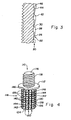
- Fig. 4 shows another embodiment of a threaded insert 110, which is a monolithic body of metal such as steel including a head 112, and an embeddable shank 114.
- Insert 110 is a male threaded insert, having a stud 116 extending axially from head 112 opposite from shank 114. Stud 116 includes a male thread 118 thereon for engaging a nut or other female threaded component to be held in position by insert 110.
- the outer surface of shank 114 defines a plurality of ridges 120 each made of a series of spire-like projections 122. Some, but not all projections 122 have been identified with reference numerals in the drawings.
- Each projection 122 includes a two-sided tip portion 126 that is narrower at the lead end thereof and wider at the trailing end thereof while being also shorter at the lead end and taller at the trailing end. At the trailing end, an enlarged cap 128 is provided, having an exposed back 130. As further shown in the exemplary embodiment, within ridge 120, inwardly from the first projection 122 each tip portion 126 begins immediately adjacent and in contact with the back 130 of the projection 120 immediately in front of thereof toward a distal or lead end 124. Ridges 120 are arranged axially along the length of shank 114, rather than angularly as are ridges 20 of insert 10 described previously.
- the surface of insert 110 is provided with nicking, being formed into a contoured surface of adjacent wedges 140 also inclining from the tips or lead ends 142 thereof to the tails or trailing ends 144 thereof.
- the trailing ends 144 form abrupt transitions or shoulders 146 to the next adjacent wedge 140. Accordingly, wedges 140 are lower at lead ends 142 and higher at trailing ends 144.
- wedges 140 extend laterally the full distance between adjacent ridges 120.
- Insert 110 can be installed as described for insert 10. Since ridges 120 are primarily axially arranged, insert 110 will not rotate significantly during a push-in type installation. However, a proper sized hole in a body of suitable material will re-form as ridges 120 embed in the material and force the material against wedges 140.
- the spire thread with root nicking on an embedded insert can provide both rotation and pullout resistance without complex undercuts on knurled formations, as used previously.
- the insert can provide the antirotation and pullout resistance performance of expensive, machined inserts, typically of brass, but with the cost advantages of a low cost, rolled steel component.
- the surface form described herein can work well for many types of inserted fasteners, including female inserts functioning as screw and bolt anchors; and male inserts for studs as described previously herein; as well as ball-ended studs designed to snap-fit into other components, or an anchored stud having any other type of end configuration suitable for the purpose.
- the stud could have a hook, a nail point, an electrical contact or other configuration, whether complex or simple.
- Other embedded male components, female components and neutral anchored devices also can use spire forms with ring shank nicking as described herein.
- the insert surfaces disclosed herein can be used for other than straight shanks as well as stepped shanks, and can be provided on all or just a portion of the embeddable length of an insert.
- Inserts 10 and 110 as well as others consistent with the teachings hereof can be manufactured efficiently from inexpensive metal, such as steel, altered in a rolling process utilizing dies to form the desired surface characteristics, including the ridges of projections and root nicking between the ridges. Accordingly, the inserts can be manufactured efficiently and inexpensively. Of course, more expensive materials can be used for installations requiring specific metal characteristics. Still other materials can be used and manufacturing processes other than a rolling process also can be used if desired.
Landscapes
- Engineering & Computer Science (AREA)
- General Engineering & Computer Science (AREA)
- Mechanical Engineering (AREA)
- Connection Of Plates (AREA)
- Mutual Connection Of Rods And Tubes (AREA)
- Insertion Pins And Rivets (AREA)
Claims (15)
- Insert d'attache (10 ; 110), comprenant :un corps d'attache encastrable, ayant une surface externe ;une pluralité de crêtes espacées (20 ; 120) faisant saillie depuis ladite surface externe ets'étendant le long de celle-ci ; etune pluralité de cales (40 ; 140) disposées entre des crêtes adjacentes (20 ; 120) de ladite pluralité de crêtes,caractérisé en ce que chacune desdites crêtes (20
; 120) comporte une série de saillies bout-à-bout (22 ; 122), chaque saillie (22 ; 122) étant pourvue à son extrémité arrière d'un capuchon agrandi (28 ; 128) ayant un dos émoussé exposé (30
; 130). - Insert d'attache selon la revendication 1, chaque dite crête (20 ; 120) comportant une série de saillies triangulaires (22 ; 122) suivant un agencement bout-à-bout.
- Insert d'attache selon la revendication 2, chaque dite saillie (22 ; 122) étant plus étroite à une extrémité qu'à une extrémité opposée, et formant une rampe depuis ladite une extrémité jusqu'à ladite extrémité opposée.
- Insert d'attache selon la revendication 3, lesdites cales (40 ; 140) ayant des extrémités inférieures (42 ; 142) et des extrémités supérieures (44 ; 144), et des transitions brutales d'une extrémité supérieure (44 ; 144) d'une cale (40 ; 140) à une extrémité inférieure (42 ; 142) d'une cale adjacente.
- Insert d'attache selon la revendication 1, comportant une ouverture axiale (16) dans ledit insert (10).
- Insert d'attache selon la revendication 1,
des crêtes adjacentes (20 ; 120) de ladite pluralité de crêtes espacées définissant des espaces inter-crêtes entre elles ;
chaque dite crête (20 ; 120) comportant une rangée de saillies bout-à-bout (22 ; 122), chaque dite saillie ayant une portion plus étroite et plus courte et une portion plus large et plus haute ; et
ladite pluralité de cales (40 ; 140) étant disposées dans chaque dit espace inter-crêtes. - Insert d'attache selon la revendication 6, chaque dite crête (120) s'étendant axialement sur ladite surface externe.
- Insert d'attache selon la revendication 6, comportant une ouverture axiale (16) dans ledit corps d'attache.
- Insert d'attache selon la revendication 6, comportant un goujon (116) s'étendant depuis ledit corps.
- Insert d'attache selon la revendication 6, qui est un corps monolithique comportant une tête (12) et une tige cylindrique (14) s'étendant depuis la tête, la tige (14) ayant une extrémité distale opposée à la tête (12), ladite surface externe comprenant :la pluralité de crêtes espacées (20) faisant saillie depuis la tige (14) et s'étendant le long de celle-ci suivant un pas de crête de telle sorte que des crêtes individuelles s'étendent sur une longueur donnée de la tige sans encercler complètement la tige ;chaque dite crête (20) comportant une rangée de saillies bout-à-bout (22) de largeurs et de hauteurs variables ; etla pluralité de cales (40) faisant saillie depuis ladite tige (14) entre des paires de crêtes adjacentes (20).
- Insert d'attache selon la revendication 10, lesdites cales (40) s'étendant depuis une crête (20) jusqu'à une autre crête (20).
- Insert d'attache selon la revendication 1 ou 6, ledit corps d'attache comportant une tête (12) et une tige (14), ladite surface externe étant une surface externe de ladite tige, et chaque dite crête (20) s'étendant sur une longueur de ladite tige (14) sans encercler complètement ladite tige.
- Insert d'attache selon la revendication 9, 10 ou 12, chaque dite crête (20) étant disposée angulairement sur ladite tige (14) et s'étendant sur la longueur de ladite tige sans encercler complètement ladite tige.
- Insert d'attache selon la revendication 10 ou 12, chaque dite crête (120) étant disposée axialement sur ladite tige (114).
- Insert d'attache selon la revendication 12, comportant un goujon (116) opposé à ladite tige (114).
Applications Claiming Priority (2)
| Application Number | Priority Date | Filing Date | Title |
|---|---|---|---|
| US32489610P | 2010-04-16 | 2010-04-16 | |
| PCT/US2011/031357 WO2011130073A1 (fr) | 2010-04-16 | 2011-04-06 | Douille de spire ayant des créneaux ménages dans une tige annulaire |
Publications (2)
| Publication Number | Publication Date |
|---|---|
| EP2558736A1 EP2558736A1 (fr) | 2013-02-20 |
| EP2558736B1 true EP2558736B1 (fr) | 2014-07-09 |
Family
ID=44070044
Family Applications (1)
| Application Number | Title | Priority Date | Filing Date |
|---|---|---|---|
| EP11714901.3A Not-in-force EP2558736B1 (fr) | 2010-04-16 | 2011-04-06 | Douille de spire ayant des créneaux ménages dans une tige annulaire |
Country Status (5)
| Country | Link |
|---|---|
| US (1) | US8651787B2 (fr) |
| EP (1) | EP2558736B1 (fr) |
| CN (1) | CN102859213B (fr) |
| BR (1) | BR112012025378A2 (fr) |
| WO (1) | WO2011130073A1 (fr) |
Families Citing this family (17)
| Publication number | Priority date | Publication date | Assignee | Title |
|---|---|---|---|---|
| US8851308B2 (en) * | 2009-12-10 | 2014-10-07 | Alcon Research, Ltd. | Systems and methods for composite frame systems |
| ES2483742T3 (es) * | 2010-03-01 | 2014-08-07 | Illinois Tool Works Inc. | Rosca en forma de cascada para insertos |
| BR112012025579A2 (pt) | 2010-04-16 | 2016-06-28 | Illinois Tool Works | inserção implantável |
| US20140241827A1 (en) * | 2013-02-22 | 2014-08-28 | Gen Co.,Ltd. | Insert nut having rectangular lattic structure and manufacturing method thereof |
| US9206831B2 (en) * | 2013-06-26 | 2015-12-08 | Itzhak Pomerantz | Dual pitch thread |
| CN203430956U (zh) * | 2013-07-19 | 2014-02-12 | 深圳富泰宏精密工业有限公司 | 螺钉套管结构 |
| DE102013217448A1 (de) | 2013-09-02 | 2015-03-05 | Böllhoff Verbindungstechnik GmbH | Verbindungseinsatz sowie ein Einbettverfahren und ein Herstellungsverfahren dafür |
| JP6324115B2 (ja) * | 2014-02-28 | 2018-05-16 | キヤノン株式会社 | インサートナット、該インサートナットを備える固定機構、該インサートナットあるいは該固定機構を備えるカートリッジ、該インサートナットあるいは該固定機構を備える用紙カセット |
| JP6338212B2 (ja) * | 2014-03-20 | 2018-06-06 | 第一工業株式会社 | 埋設型ナット、埋設型ナットの製造方法、および埋設型ナット装着部品 |
| US9856902B2 (en) * | 2015-01-23 | 2018-01-02 | Spirol International Corporation | Extruded metal insert |
| JP1583795S (fr) * | 2016-12-22 | 2017-08-14 | ||
| WO2019099287A1 (fr) * | 2017-11-14 | 2019-05-23 | Penn Engineering & Manufacturing Corp. | Élément de fixation par appui, doté de tige moletée ondulée |
| TWM572937U (zh) * | 2018-03-28 | 2019-01-11 | 世豐螺絲股份有限公司 | Screw with irregular embossing pattern |
| CN110685987B (zh) * | 2018-07-06 | 2024-03-15 | 宾工程工厂公司 | 一种压入式紧固件及包括其的组件 |
| WO2020083458A1 (fr) | 2018-10-21 | 2020-04-30 | Mozetic Domen | Élément de fixation de type cheville auto-bloquant à nervure en spirale |
| US11486520B2 (en) * | 2019-07-25 | 2022-11-01 | Newfrey Llc | Press-fit, friction-retention coupling assembly between hard, inflexible material components |
| DE102020205566A1 (de) | 2020-04-30 | 2021-11-04 | Berrang Entwicklungsgmbh | Metalleinsatz zur Verwendung in Kunststoffbauteilen |
Family Cites Families (22)
| Publication number | Priority date | Publication date | Assignee | Title |
|---|---|---|---|---|
| US2949142A (en) * | 1957-08-16 | 1960-08-16 | Paul J Sumerak | Threaded insert with projections |
| US3081808A (en) * | 1960-07-25 | 1963-03-19 | Rosan Eng Corp | Thin-walled inserts and method of making same |
| US3362281A (en) * | 1966-02-25 | 1968-01-09 | Fastener Products Inc | Insert bushing |
| US3405591A (en) * | 1966-11-28 | 1968-10-15 | Neuschotz Robert | Threaded elements having deformable spacers |
| DE1978882U (de) * | 1967-08-01 | 1968-02-15 | Siegfried Kirchhoff | Duebel. |
| IL34249A0 (en) * | 1969-04-10 | 1970-06-17 | Penn Eng & Mfg Corp | Fastener |
| GB1549199A (en) * | 1975-07-08 | 1979-08-01 | Barnsdale A D | Insert |
| USD262863S (en) * | 1978-07-29 | 1982-02-02 | Barnsdale Arthur D | Insert for fixing or fastening purposes |
| US4712955A (en) * | 1985-05-14 | 1987-12-15 | Rexnord Inc. | Expandable fastener assembly |
| FR2636685B1 (fr) * | 1988-09-19 | 1991-01-11 | Vape Sa Ets | Dispositif de fixation a vis dans un element de construction en beton |
| DE4000782A1 (de) * | 1990-01-12 | 1991-08-08 | Boellhoff & Co | Gewindeeinsatz |
| US5391031A (en) * | 1992-05-22 | 1995-02-21 | Unimation, Inc. | Method and insert for connecting components to plastic members |
| US5697744A (en) * | 1992-05-22 | 1997-12-16 | Unimation, Inc. | Method and insert for connecting components to plastic members |
| DE4403131A1 (de) * | 1994-02-02 | 1995-08-03 | Fischer Artur Werke Gmbh | Ankerbolzen zur Verankerung mittels einer Verbundmasse und Verfahren zu dessen Herstellung |
| DE19856611A1 (de) * | 1998-12-08 | 2000-06-15 | Boellhoff Gmbh | Metallischer Einsatz |
| DE10013091A1 (de) * | 2000-03-17 | 2001-09-20 | Boellhoff Gmbh | Metallischer Einsatz mit Rippen |
| US6676352B2 (en) * | 2001-03-13 | 2004-01-13 | Ju-Ching Chen-Chi | Fasteners with improved retaining effect |
| US7934895B2 (en) * | 2003-10-10 | 2011-05-03 | Illinois Tool Works Inc. | Self-drilling anchor |
| DE102004049489B3 (de) * | 2004-10-11 | 2006-03-30 | Hilti Ag | Ankerelement |
| JP4395465B2 (ja) * | 2005-07-11 | 2010-01-06 | 永山電子工業株式会社 | インサートナット及びインサートtナット |
| JP2009079666A (ja) * | 2007-09-26 | 2009-04-16 | Nagayama Denshi Kogyo Kk | インサートナット |
| US7819614B2 (en) | 2007-12-14 | 2010-10-26 | Illinois Tool Works, Inc. | Deformed shank fastener |
-
2011
- 2011-04-06 BR BR112012025378A patent/BR112012025378A2/pt not_active Application Discontinuation
- 2011-04-06 CN CN201180019083.3A patent/CN102859213B/zh not_active Expired - Fee Related
- 2011-04-06 WO PCT/US2011/031357 patent/WO2011130073A1/fr active Application Filing
- 2011-04-06 US US13/635,974 patent/US8651787B2/en not_active Expired - Fee Related
- 2011-04-06 EP EP11714901.3A patent/EP2558736B1/fr not_active Not-in-force
Also Published As
| Publication number | Publication date |
|---|---|
| US20130017032A1 (en) | 2013-01-17 |
| BR112012025378A2 (pt) | 2016-06-28 |
| US8651787B2 (en) | 2014-02-18 |
| CN102859213B (zh) | 2015-04-29 |
| EP2558736A1 (fr) | 2013-02-20 |
| CN102859213A (zh) | 2013-01-02 |
| WO2011130073A1 (fr) | 2011-10-20 |
Similar Documents
| Publication | Publication Date | Title |
|---|---|---|
| EP2558736B1 (fr) | Douille de spire ayant des créneaux ménages dans une tige annulaire | |
| EP2558275B1 (fr) | Insert encastreable | |
| EP2542792B1 (fr) | Fil en forme de cascade pour inserts | |
| US9322424B2 (en) | Nut with lug flare | |
| US8974163B2 (en) | Wedge-type drop-in anchor assembly | |
| US8974164B2 (en) | Plastic high heat fastener | |
| EP2257715B1 (fr) | Attache femelle à autofermeture | |
| EP2092203B1 (fr) | Insert de goujon borgne | |
| JPH02118208A (ja) | 締付具と保持リングの組立体 | |
| US10385897B2 (en) | Dowel element, fastening device, method for producing a dowel element, and method for installing a fastening device | |
| EP1856419A2 (fr) | Element de boulonnerie a auto-fixation et ensemble element de boulonnerie et panneau | |
| WO2010037535A1 (fr) | Dispositif de fixation | |
| US20070212191A1 (en) | Two piece weld nut | |
| EP2034193B1 (fr) | Système destiné à la fixation d'éléments, en particulier pour les véhicules automobiles | |
| EP3447316A1 (fr) | Corps de vis mâle, corps de vis femelle, procédé de conception de corps de vis, structure de filet | |
| US20080067811A1 (en) | Fastener assembly and manufacturing method therefor | |
| US20070253770A1 (en) | Joined connection, joining element and method for inserting a joining element into a component | |
| US20140186135A1 (en) | Threaded fastener | |
| EP0097111B1 (fr) | Anneau de sécurité comportant un manchon ou un goujon d'un seul tenant | |
| CN115704416A (zh) | 紧固件插入件 | |
| CA2665753A1 (fr) | Methode de formage d'un manchon de montage d'expansion et produit connexe | |
| CN115803500A (zh) | 锚固螺栓 | |
| EP2331830A1 (fr) | Dispositif de fixation |
Legal Events
| Date | Code | Title | Description |
|---|---|---|---|
| PUAI | Public reference made under article 153(3) epc to a published international application that has entered the european phase |
Free format text: ORIGINAL CODE: 0009012 |
|
| 17P | Request for examination filed |
Effective date: 20121008 |
|
| AK | Designated contracting states |
Kind code of ref document: A1 Designated state(s): AL AT BE BG CH CY CZ DE DK EE ES FI FR GB GR HR HU IE IS IT LI LT LU LV MC MK MT NL NO PL PT RO RS SE SI SK SM TR |
|
| DAX | Request for extension of the european patent (deleted) | ||
| 17Q | First examination report despatched |
Effective date: 20131031 |
|
| GRAP | Despatch of communication of intention to grant a patent |
Free format text: ORIGINAL CODE: EPIDOSNIGR1 |
|
| RAP1 | Party data changed (applicant data changed or rights of an application transferred) |
Owner name: ILLINOIS TOOL WORKS INC. |
|
| INTG | Intention to grant announced |
Effective date: 20140409 |
|
| GRAS | Grant fee paid |
Free format text: ORIGINAL CODE: EPIDOSNIGR3 |
|
| GRAA | (expected) grant |
Free format text: ORIGINAL CODE: 0009210 |
|
| AK | Designated contracting states |
Kind code of ref document: B1 Designated state(s): AL AT BE BG CH CY CZ DE DK EE ES FI FR GB GR HR HU IE IS IT LI LT LU LV MC MK MT NL NO PL PT RO RS SE SI SK SM TR |
|
| REG | Reference to a national code |
Ref country code: GB Ref legal event code: FG4D |
|
| REG | Reference to a national code |
Ref country code: CH Ref legal event code: EP Ref country code: AT Ref legal event code: REF Ref document number: 676688 Country of ref document: AT Kind code of ref document: T Effective date: 20140715 |
|
| REG | Reference to a national code |
Ref country code: IE Ref legal event code: FG4D |
|
| REG | Reference to a national code |
Ref country code: DE Ref legal event code: R096 Ref document number: 602011008265 Country of ref document: DE Effective date: 20140821 |
|
| REG | Reference to a national code |
Ref country code: AT Ref legal event code: MK05 Ref document number: 676688 Country of ref document: AT Kind code of ref document: T Effective date: 20140709 |
|
| REG | Reference to a national code |
Ref country code: NL Ref legal event code: VDEP Effective date: 20140709 |
|
| REG | Reference to a national code |
Ref country code: LT Ref legal event code: MG4D |
|
| PG25 | Lapsed in a contracting state [announced via postgrant information from national office to epo] |
Ref country code: SE Free format text: LAPSE BECAUSE OF FAILURE TO SUBMIT A TRANSLATION OF THE DESCRIPTION OR TO PAY THE FEE WITHIN THE PRESCRIBED TIME-LIMIT Effective date: 20140709 Ref country code: FI Free format text: LAPSE BECAUSE OF FAILURE TO SUBMIT A TRANSLATION OF THE DESCRIPTION OR TO PAY THE FEE WITHIN THE PRESCRIBED TIME-LIMIT Effective date: 20140709 Ref country code: BG Free format text: LAPSE BECAUSE OF FAILURE TO SUBMIT A TRANSLATION OF THE DESCRIPTION OR TO PAY THE FEE WITHIN THE PRESCRIBED TIME-LIMIT Effective date: 20141009 Ref country code: GR Free format text: LAPSE BECAUSE OF FAILURE TO SUBMIT A TRANSLATION OF THE DESCRIPTION OR TO PAY THE FEE WITHIN THE PRESCRIBED TIME-LIMIT Effective date: 20141010 Ref country code: ES Free format text: LAPSE BECAUSE OF FAILURE TO SUBMIT A TRANSLATION OF THE DESCRIPTION OR TO PAY THE FEE WITHIN THE PRESCRIBED TIME-LIMIT Effective date: 20140709 Ref country code: LT Free format text: LAPSE BECAUSE OF FAILURE TO SUBMIT A TRANSLATION OF THE DESCRIPTION OR TO PAY THE FEE WITHIN THE PRESCRIBED TIME-LIMIT Effective date: 20140709 Ref country code: PT Free format text: LAPSE BECAUSE OF FAILURE TO SUBMIT A TRANSLATION OF THE DESCRIPTION OR TO PAY THE FEE WITHIN THE PRESCRIBED TIME-LIMIT Effective date: 20141110 Ref country code: NO Free format text: LAPSE BECAUSE OF FAILURE TO SUBMIT A TRANSLATION OF THE DESCRIPTION OR TO PAY THE FEE WITHIN THE PRESCRIBED TIME-LIMIT Effective date: 20141009 |
|
| PG25 | Lapsed in a contracting state [announced via postgrant information from national office to epo] |
Ref country code: RS Free format text: LAPSE BECAUSE OF FAILURE TO SUBMIT A TRANSLATION OF THE DESCRIPTION OR TO PAY THE FEE WITHIN THE PRESCRIBED TIME-LIMIT Effective date: 20140709 Ref country code: NL Free format text: LAPSE BECAUSE OF FAILURE TO SUBMIT A TRANSLATION OF THE DESCRIPTION OR TO PAY THE FEE WITHIN THE PRESCRIBED TIME-LIMIT Effective date: 20140709 Ref country code: HR Free format text: LAPSE BECAUSE OF FAILURE TO SUBMIT A TRANSLATION OF THE DESCRIPTION OR TO PAY THE FEE WITHIN THE PRESCRIBED TIME-LIMIT Effective date: 20140709 Ref country code: PL Free format text: LAPSE BECAUSE OF FAILURE TO SUBMIT A TRANSLATION OF THE DESCRIPTION OR TO PAY THE FEE WITHIN THE PRESCRIBED TIME-LIMIT Effective date: 20140709 Ref country code: IS Free format text: LAPSE BECAUSE OF FAILURE TO SUBMIT A TRANSLATION OF THE DESCRIPTION OR TO PAY THE FEE WITHIN THE PRESCRIBED TIME-LIMIT Effective date: 20141109 Ref country code: AT Free format text: LAPSE BECAUSE OF FAILURE TO SUBMIT A TRANSLATION OF THE DESCRIPTION OR TO PAY THE FEE WITHIN THE PRESCRIBED TIME-LIMIT Effective date: 20140709 Ref country code: LV Free format text: LAPSE BECAUSE OF FAILURE TO SUBMIT A TRANSLATION OF THE DESCRIPTION OR TO PAY THE FEE WITHIN THE PRESCRIBED TIME-LIMIT Effective date: 20140709 Ref country code: CY Free format text: LAPSE BECAUSE OF FAILURE TO SUBMIT A TRANSLATION OF THE DESCRIPTION OR TO PAY THE FEE WITHIN THE PRESCRIBED TIME-LIMIT Effective date: 20140709 |
|
| REG | Reference to a national code |
Ref country code: DE Ref legal event code: R097 Ref document number: 602011008265 Country of ref document: DE |
|
| PG25 | Lapsed in a contracting state [announced via postgrant information from national office to epo] |
Ref country code: IT Free format text: LAPSE BECAUSE OF FAILURE TO SUBMIT A TRANSLATION OF THE DESCRIPTION OR TO PAY THE FEE WITHIN THE PRESCRIBED TIME-LIMIT Effective date: 20140709 Ref country code: CZ Free format text: LAPSE BECAUSE OF FAILURE TO SUBMIT A TRANSLATION OF THE DESCRIPTION OR TO PAY THE FEE WITHIN THE PRESCRIBED TIME-LIMIT Effective date: 20140709 Ref country code: DK Free format text: LAPSE BECAUSE OF FAILURE TO SUBMIT A TRANSLATION OF THE DESCRIPTION OR TO PAY THE FEE WITHIN THE PRESCRIBED TIME-LIMIT Effective date: 20140709 Ref country code: RO Free format text: LAPSE BECAUSE OF FAILURE TO SUBMIT A TRANSLATION OF THE DESCRIPTION OR TO PAY THE FEE WITHIN THE PRESCRIBED TIME-LIMIT Effective date: 20140709 Ref country code: SK Free format text: LAPSE BECAUSE OF FAILURE TO SUBMIT A TRANSLATION OF THE DESCRIPTION OR TO PAY THE FEE WITHIN THE PRESCRIBED TIME-LIMIT Effective date: 20140709 Ref country code: EE Free format text: LAPSE BECAUSE OF FAILURE TO SUBMIT A TRANSLATION OF THE DESCRIPTION OR TO PAY THE FEE WITHIN THE PRESCRIBED TIME-LIMIT Effective date: 20140709 |
|
| PLBE | No opposition filed within time limit |
Free format text: ORIGINAL CODE: 0009261 |
|
| STAA | Information on the status of an ep patent application or granted ep patent |
Free format text: STATUS: NO OPPOSITION FILED WITHIN TIME LIMIT |
|
| 26N | No opposition filed |
Effective date: 20150410 |
|
| PG25 | Lapsed in a contracting state [announced via postgrant information from national office to epo] |
Ref country code: MC Free format text: LAPSE BECAUSE OF FAILURE TO SUBMIT A TRANSLATION OF THE DESCRIPTION OR TO PAY THE FEE WITHIN THE PRESCRIBED TIME-LIMIT Effective date: 20140709 Ref country code: LU Free format text: LAPSE BECAUSE OF FAILURE TO SUBMIT A TRANSLATION OF THE DESCRIPTION OR TO PAY THE FEE WITHIN THE PRESCRIBED TIME-LIMIT Effective date: 20150406 Ref country code: SI Free format text: LAPSE BECAUSE OF FAILURE TO SUBMIT A TRANSLATION OF THE DESCRIPTION OR TO PAY THE FEE WITHIN THE PRESCRIBED TIME-LIMIT Effective date: 20140709 |
|
| REG | Reference to a national code |
Ref country code: CH Ref legal event code: PL |
|
| GBPC | Gb: european patent ceased through non-payment of renewal fee |
Effective date: 20150406 |
|
| REG | Reference to a national code |
Ref country code: IE Ref legal event code: MM4A |
|
| PG25 | Lapsed in a contracting state [announced via postgrant information from national office to epo] |
Ref country code: GB Free format text: LAPSE BECAUSE OF NON-PAYMENT OF DUE FEES Effective date: 20150406 Ref country code: CH Free format text: LAPSE BECAUSE OF NON-PAYMENT OF DUE FEES Effective date: 20150430 Ref country code: LI Free format text: LAPSE BECAUSE OF NON-PAYMENT OF DUE FEES Effective date: 20150430 |
|
| REG | Reference to a national code |
Ref country code: FR Ref legal event code: PLFP Year of fee payment: 6 |
|
| PG25 | Lapsed in a contracting state [announced via postgrant information from national office to epo] |
Ref country code: IE Free format text: LAPSE BECAUSE OF NON-PAYMENT OF DUE FEES Effective date: 20150406 |
|
| PG25 | Lapsed in a contracting state [announced via postgrant information from national office to epo] |
Ref country code: BE Free format text: LAPSE BECAUSE OF FAILURE TO SUBMIT A TRANSLATION OF THE DESCRIPTION OR TO PAY THE FEE WITHIN THE PRESCRIBED TIME-LIMIT Effective date: 20140709 |
|
| PG25 | Lapsed in a contracting state [announced via postgrant information from national office to epo] |
Ref country code: MT Free format text: LAPSE BECAUSE OF FAILURE TO SUBMIT A TRANSLATION OF THE DESCRIPTION OR TO PAY THE FEE WITHIN THE PRESCRIBED TIME-LIMIT Effective date: 20140709 |
|
| REG | Reference to a national code |
Ref country code: FR Ref legal event code: PLFP Year of fee payment: 7 |
|
| PG25 | Lapsed in a contracting state [announced via postgrant information from national office to epo] |
Ref country code: HU Free format text: LAPSE BECAUSE OF FAILURE TO SUBMIT A TRANSLATION OF THE DESCRIPTION OR TO PAY THE FEE WITHIN THE PRESCRIBED TIME-LIMIT; INVALID AB INITIO Effective date: 20110406 Ref country code: SM Free format text: LAPSE BECAUSE OF FAILURE TO SUBMIT A TRANSLATION OF THE DESCRIPTION OR TO PAY THE FEE WITHIN THE PRESCRIBED TIME-LIMIT Effective date: 20140709 |
|
| PG25 | Lapsed in a contracting state [announced via postgrant information from national office to epo] |
Ref country code: TR Free format text: LAPSE BECAUSE OF FAILURE TO SUBMIT A TRANSLATION OF THE DESCRIPTION OR TO PAY THE FEE WITHIN THE PRESCRIBED TIME-LIMIT Effective date: 20140709 |
|
| REG | Reference to a national code |
Ref country code: FR Ref legal event code: PLFP Year of fee payment: 8 |
|
| PG25 | Lapsed in a contracting state [announced via postgrant information from national office to epo] |
Ref country code: MK Free format text: LAPSE BECAUSE OF FAILURE TO SUBMIT A TRANSLATION OF THE DESCRIPTION OR TO PAY THE FEE WITHIN THE PRESCRIBED TIME-LIMIT Effective date: 20140709 |
|
| PGFP | Annual fee paid to national office [announced via postgrant information from national office to epo] |
Ref country code: DE Payment date: 20180427 Year of fee payment: 8 |
|
| PGFP | Annual fee paid to national office [announced via postgrant information from national office to epo] |
Ref country code: FR Payment date: 20180425 Year of fee payment: 8 |
|
| PG25 | Lapsed in a contracting state [announced via postgrant information from national office to epo] |
Ref country code: AL Free format text: LAPSE BECAUSE OF FAILURE TO SUBMIT A TRANSLATION OF THE DESCRIPTION OR TO PAY THE FEE WITHIN THE PRESCRIBED TIME-LIMIT Effective date: 20140709 |
|
| REG | Reference to a national code |
Ref country code: DE Ref legal event code: R119 Ref document number: 602011008265 Country of ref document: DE |
|
| PG25 | Lapsed in a contracting state [announced via postgrant information from national office to epo] |
Ref country code: DE Free format text: LAPSE BECAUSE OF NON-PAYMENT OF DUE FEES Effective date: 20191101 |
|
| PG25 | Lapsed in a contracting state [announced via postgrant information from national office to epo] |
Ref country code: FR Free format text: LAPSE BECAUSE OF NON-PAYMENT OF DUE FEES Effective date: 20190430 |