EP2558736B1 - Spire insert with ring-shank nicking - Google Patents
Spire insert with ring-shank nicking Download PDFInfo
- Publication number
- EP2558736B1 EP2558736B1 EP11714901.3A EP11714901A EP2558736B1 EP 2558736 B1 EP2558736 B1 EP 2558736B1 EP 11714901 A EP11714901 A EP 11714901A EP 2558736 B1 EP2558736 B1 EP 2558736B1
- Authority
- EP
- European Patent Office
- Prior art keywords
- shank
- insert
- ridge
- ridges
- fastener insert
- Prior art date
- Legal status (The legal status is an assumption and is not a legal conclusion. Google has not performed a legal analysis and makes no representation as to the accuracy of the status listed.)
- Not-in-force
Links
- 230000007704 transition Effects 0.000 claims description 4
- 239000000463 material Substances 0.000 description 17
- 229920003023 plastic Polymers 0.000 description 12
- 239000004033 plastic Substances 0.000 description 12
- 238000000034 method Methods 0.000 description 8
- 239000002184 metal Substances 0.000 description 7
- 238000003780 insertion Methods 0.000 description 6
- 230000037431 insertion Effects 0.000 description 6
- 229910000831 Steel Inorganic materials 0.000 description 5
- 239000010959 steel Substances 0.000 description 5
- 229910001369 Brass Inorganic materials 0.000 description 3
- 230000015572 biosynthetic process Effects 0.000 description 3
- 239000010951 brass Substances 0.000 description 3
- 238000005755 formation reaction Methods 0.000 description 3
- 238000009434 installation Methods 0.000 description 3
- 238000005096 rolling process Methods 0.000 description 3
- 238000003754 machining Methods 0.000 description 2
- 238000004519 manufacturing process Methods 0.000 description 2
- 239000012768 molten material Substances 0.000 description 2
- 238000004873 anchoring Methods 0.000 description 1
- 230000000712 assembly Effects 0.000 description 1
- 238000000429 assembly Methods 0.000 description 1
- 238000010276 construction Methods 0.000 description 1
- 239000007788 liquid Substances 0.000 description 1
- 238000010297 mechanical methods and process Methods 0.000 description 1
- 230000005226 mechanical processes and functions Effects 0.000 description 1
- 238000002844 melting Methods 0.000 description 1
- 230000008018 melting Effects 0.000 description 1
- 238000000465 moulding Methods 0.000 description 1
- 230000007935 neutral effect Effects 0.000 description 1
Images

Classifications
-
- F—MECHANICAL ENGINEERING; LIGHTING; HEATING; WEAPONS; BLASTING
- F16—ENGINEERING ELEMENTS AND UNITS; GENERAL MEASURES FOR PRODUCING AND MAINTAINING EFFECTIVE FUNCTIONING OF MACHINES OR INSTALLATIONS; THERMAL INSULATION IN GENERAL
- F16B—DEVICES FOR FASTENING OR SECURING CONSTRUCTIONAL ELEMENTS OR MACHINE PARTS TOGETHER, e.g. NAILS, BOLTS, CIRCLIPS, CLAMPS, CLIPS OR WEDGES; JOINTS OR JOINTING
- F16B37/00—Nuts or like thread-engaging members
- F16B37/12—Nuts or like thread-engaging members with thread-engaging surfaces formed by inserted coil-springs, discs, or the like; Independent pieces of wound wire used as nuts; Threaded inserts for holes
- F16B37/122—Threaded inserts, e.g. "rampa bolts"
Description
- The present invention relates generally to fasteners and fastening systems, and, more particularly, to fastener components of fastening systems that are embedded in another part, often of dissimilar material.
- It is known to provide fastening systems that include threaded inserts of metal that are anchored in plastic or other components when used to receive a screw or bolt for holding a second component in an assembly. For example, plastic parts in automobiles, computers, appliances of different types, and various other assemblies are known to be provided with metal inserts having internal threads so that another part can be held thereto by a bolt or screw engaged with the insert. It is also known to anchor a threaded stud in a plastic or other part so that another component can be held there on by a nut threaded onto the threads of the stud.
US 2002/0021 948 A discloses an insert having a recessed portion comprising an annular groove and being provided with a pair of radial ribs offset by 180° which can extend into truncated cones. The portions of the ribs within the annular groove abut against an annular flange.DE 19 78 882 U describes a dowel having a plurality of ridges, however no wedges disposed between adjacent ridges. It shows different embodiments having projections closely spaced, more widely spaced or somewhat randomly positioned. - Various techniques are known for securing the anchored component, such as a threaded insert or stud, in the plastic or other part. Simple threaded engagement can be used, with threads on the outer surface of the insert or stud threaded into the component in which it is held. In a process known as heat-staking, a metal part, such as a threaded female insert or stud, is heated and pushed into the plastic component in which it is held, melting and fusing the inter-facing plastic surface on to the embedded portion of the insert or stud. Heat-staking can be performed relatively inexpensively. Ultrasonic insertion is also known whereby the part is vibrated ultrasonically and pushed into the receiving component. Ultrasonic insertion can be performed relatively quickly, but the process tends to be expensive. In a more simple mechanical process, the component to be anchored is provided with a knurled or other configured outer surface and is simply pushed into the receiving component. Mechanical insertion such as this can be performed quickly, but the machining process required to form the outer surface of the insert adds significantly to overall cost. Further, mechanical insertion tends to channel or direct the material of the anchoring component, and it has been difficult to achieve significant holding strength against pullout with push-in inserts. Further, to facilitate easy and rapid machining of inserts, it has been known to use expensive materials, such as brass, for inserts installed by all such methods. Knurls, undercuts and other such formations can be formed readily in brass; however, the costs of parts made of such materials are high.
- Advantages can be obtained from providing an insert that can be driven readily while providing significant resistance to both pullout and rotation in the completed assembly. Further advantages are realized if the insert can be manufactured easily from inexpensive materials using simple and efficient manufacturing processes.
- An embeddable spire insert is disclosed herein with ring-shank nicking which can be manufactured efficiently and quickly by rolling processes utilizing dies and lesser expensive materials, such as steel. A plurality of ridges of outwardly extending projections is provided. The ridges may be axially oriented or helical or spiral type threads. The projections are formed as adjacently arranged bodies. Wedges are provided in the root areas between the ridges.
- According to the present invention an insert is provided with an embeddable body having an external surface, a plurality of spaced ridges projecting from and extending along the external surface, and a plurality of wedges disposed between adjacent ridges of the plurality of ridges. Each of said ridges includes a series of end-to-end projections, each projection being provided with its trailing end with an enlarged cap having an exposed blunt back.
- Other features and advantages of the invention will become apparent to those skilled in the art upon review of the following detailed description, claims and drawings in which like numerals are used to designate like features.
-
-
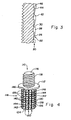
Fig. 1 is a perspective view of a female threaded insert with ring-shank nicking; -
Fig. 2 is an enlarged, fragmentary perspective view of the outer surface of the insert shown inFig. 1 ; -
Fig. 3 is an enlarged, fragmentary, cross-sectional view of the insert; and -
Fig. 4 is a perspective view of a male stud insert. - Before the embodiments of the invention are explained in detail, it is to be understood that the invention is not limited in its application to the details of construction and the arrangements of the components set forth in the following description or illustrated in the drawings. The invention is capable of other embodiments and of being practiced or being carried out in various ways. Also, it is understood that the phraseology and terminology used herein are for the purpose of description and should not be regarded as limiting. The use herein of "including", "comprising" and variations thereof is meant to encompass the items listed thereafter and equivalents thereof, as well as additional items and equivalents thereof.
- Referring now more specifically to the drawings and particularly to
Fig. 1 , anembeddable insert 10 is shown. Insert 10 is a female threaded insert having a monolithic body of metal such as steel that includes ahead 12 and ashank 14 defining an axial opening 16 therethrough which includes afemale thread 18 therein. - The outer surface of
shank 14 defines a plurality ofridges 20, eachridge 20 being a row of spire-like projections 22. Some, but not allprojections 22 have been identified with reference numerals in the drawings. The ridges can be axially or longitudinally arranged, or can be helical or spiral to encourage a rotational movement of the insert as the insert is driven into a body of plastic or other material. In the exemplary embodiment shown, eachridge 20 extends angularly relative to the axial extent ofshank 14, extending along a helical path onshank 14 at a given pitch which does not result in anyridge 20 completely encirclingshank 14.Adjacent ridges 20 are somewhat distantly spaced defining relatively wide inter-ridge spaces there between. It should be understood however thatridges 20 can be more angularly or less angularly oriented than as shown and can be more closely or more distantly spaced from one another. -
Projections 22 can be formed as generally triangular shaped teeth aligned one adjacent another in an end-to-end relationship, with eachprojection 22 inclining away from a distal orlead end 24 of the insert. Accordingly, eachindividual projection 22 forms a ramp-like structure facilitating mechanical insertion into a retaining body. The projections can take many different shapes, and, as shown in the exemplary embodiment, may be narrower at the tips or lead ends thereof and broader at the tails or trailing ends while also inclining from the tips to the tails, thus being shorter at the tip and taller at the tail. Each projection may also form a steep back to meet the tip of the next adjacent projection. Sides of the projections may be flat or contoured, and may be at angles with respect to one another to form a narrow outer ridge from tip to tail. The steep backs of the projections resist pull-out of the insert, and the sides of the projections provide resistance against rotation after the insert is in final position and seated in the retaining body. For example and not limitation, projections shaped as described for use on a nail in United States Patent Application PublicationUS 2009/0155021 can be used, as well as projections of other shapes and configurations. - In the exemplary embodiment as shown most clearly in
Fig. 2 , eachprojection 22 includes a two-sided tip portion 26 that is narrower at the lead end thereof and wider at the trailing end thereof while also being shorter at the lead end and taller at the trailing end while being also shorter at the lead end and taller at the trailing end. At the trailing end, an enlargedcap 28 is provided, having an exposed, blunt back 30. As further shown in the exemplary embodiment, withinridge 20, inwardly from thefirst projection 22 eachtip portion 26 begins immediately adjacent and in contact with theback 30 of the projection immediately in front thereof towardlead end 24. This exemplary configuration is merely one suitable formation, and projections of other shapes, relative sizes and the like also can be used. - In the root or inter-ridge areas between
adjacent ridges 20, the surface of the insert is provided with nicking, being formed into a contoured surface of adjacent wedges.Wedges 40 also incline from the tips orlead ends 42 thereof to the tails or trailingends 44 thereof, thetrailing ends 44 forming abrupt transitions orshoulders 46 to the nextadjacent wedge 40. Accordingly,wedges 40 are lower atlead ends 42 and higher attrailing ends 44. In the exemplary embodiment,wedges 40 extend laterally the full distance betweenadjacent ridges 20. Some, but not allwedges 40 and some, but not all lead ends 42, trailing ends 44 andshoulders 46 have been identified with reference numbers in the drawings. The abrupt transitions of the trailing ends 44 resist pullout of the insert as well as "screw out" from reverse rotation of inserts having helical screw thread-like ridges 20. The wedges increase the resistance to pull out without changing the outer diameter of the insert. - When
insert 10 havingangular ridges 20 ofprojections 22 is pushed into a hole formed in a plastic body, for example,ridges 20 acting as screw threads to displace the plastic and force the displaced plastic to press against the root area of the insert.Insert 10 can rotate slightly as it is being inserted.Wedges 40 in the root areas provide surfaces for the plastic to flow into and against; thereby increasing the resistance to tensile as well as rotational forces that otherwise would tend to withdraw the insert from a body in which it is anchored. - Inserts as described herein are particularly suitable for "push-in" type installation methods, but can be used in a variety of other application methods, including but not limited to heat staking, and ultrasonic insertion. Further, direct placement in molded components during the molding process, or subsequent fill of molten material in a pocket including the insert also can suitably anchor inserts as described herein by injecting molten material around the body. Inserts as described herein also may work well when anchored in components of material other than plastics when the material immediately adjacent and surrounding the insert is provided in a molten or liquid state to fill closely around
projections 22 andwedges 40, or is soft enough to yield and deform from theridges 20 being pushed therein. - The most advantageous processes for installing the insert will cause material of the body in which the insert is installed to flow into the root areas between adjacent ridges of projections. With good fill in the root areas from a proper sized hole, the displaced material is reformed against
wedges 40 to provide strength against rotation and pullout from the generally axial and generally circumferential faces of theprojections 22 andwedges 40. The substantially axial sides of the projections resist rotation of the insert in the receiving component, and the substantially circumferential portions ofbacks 26 and trailing ends 44 resist pullout of the insert from the receiving component. The length, height, frequency and helical orientation of theprojections 22 andwedges 40 can be selected to achieve the desired drivability and resistance to both pullout and rotation of a particular insert in a specific material. -
Fig. 4 shows another embodiment of a threadedinsert 110, which is a monolithic body of metal such as steel including ahead 112, and anembeddable shank 114.Insert 110 is a male threaded insert, having astud 116 extending axially fromhead 112 opposite fromshank 114.Stud 116 includes amale thread 118 thereon for engaging a nut or other female threaded component to be held in position byinsert 110. The outer surface ofshank 114 defines a plurality ofridges 120 each made of a series of spire-like projections 122. Some, but not allprojections 122 have been identified with reference numerals in the drawings. Eachprojection 122 includes a two-sided tip portion 126 that is narrower at the lead end thereof and wider at the trailing end thereof while being also shorter at the lead end and taller at the trailing end. At the trailing end, anenlarged cap 128 is provided, having an exposed back 130. As further shown in the exemplary embodiment, withinridge 120, inwardly from thefirst projection 122 each tip portion 126 begins immediately adjacent and in contact with the back 130 of theprojection 120 immediately in front of thereof toward a distal orlead end 124.Ridges 120 are arranged axially along the length ofshank 114, rather than angularly as areridges 20 ofinsert 10 described previously. - In the root areas between
adjacent ridges 120, the surface ofinsert 110 is provided with nicking, being formed into a contoured surface ofadjacent wedges 140 also inclining from the tips or lead ends 142 thereof to the tails or trailing ends 144 thereof. The trailing ends 144 form abrupt transitions orshoulders 146 to the nextadjacent wedge 140. Accordingly,wedges 140 are lower at lead ends 142 and higher at trailing ends 144. In the exemplary embodiment,wedges 140 extend laterally the full distance betweenadjacent ridges 120. Some, but not allwedges 140 and some, but not all lead ends 142, trailing ends 144 andshoulders 146 have been identified with reference numbers in the drawings. -
Insert 110 can be installed as described forinsert 10. Sinceridges 120 are primarily axially arranged, insert 110 will not rotate significantly during a push-in type installation. However, a proper sized hole in a body of suitable material will re-form asridges 120 embed in the material and force the material againstwedges 140. - The spire thread with root nicking on an embedded insert can provide both rotation and pullout resistance without complex undercuts on knurled formations, as used previously. As a result, the insert can provide the antirotation and pullout resistance performance of expensive, machined inserts, typically of brass, but with the cost advantages of a low cost, rolled steel component. The surface form described herein can work well for many types of inserted fasteners, including female inserts functioning as screw and bolt anchors; and male inserts for studs as described previously herein; as well as ball-ended studs designed to snap-fit into other components, or an anchored stud having any other type of end configuration suitable for the purpose. For example, the stud could have a hook, a nail point, an electrical contact or other configuration, whether complex or simple. Other embedded male components, female components and neutral anchored devices also can use spire forms with ring shank nicking as described herein. Further, the insert surfaces disclosed herein can be used for other than straight shanks as well as stepped shanks, and can be provided on all or just a portion of the embeddable length of an insert.
-
Inserts
Claims (15)
- A fastener insert (10; 110), comprising:an embeddable fastener body having an external surface;a plurality of spaced ridges (20; 120) projecting from and extending along said external surface; anda plurality of wedges (40; 140) disposed between adjacent ridges (20; 120) of said plurality of ridges,characterized in that each of said ridges (20; 120) including a series of end-to-end projections (22; 122), each projection (22; 122) being provided with its trailing end with an enlarged cap (28; 128) having an exposed blunt back (30; 130).
- The fastener insert of claim 1, each said ridge (20; 120) including a series of triangular projections (22; 122) in end-to-end arrangement.
- The fastener insert of claim 2, each said projection (22; 122) being narrower at one end than at an opposite end, and forming a ramp from said one end to said opposite end.
- The fastener insert of claim 3, said wedges (40; 140) having lower ends (42; 142) and higher ends (44; 144), and blunt transitions from a higher end (44; 144) of one wedge (40; 140) to a lower end (42; 142) of an adjacent wedge.
- The fastener insert of claim 1, including an axial opening (16) in said insert (10).
- The fastener insert of claim 1,
adjacent ridges (20; 120) of said plurality of spaced ridges defining inter-ridge spaces therebetween;
each said ridge (20; 120) including a row of end-to-end projections (22; 122), each said projection having a narrower and shorter portion and a wider portion and taller portion; and
said plurality of wedges (40; 140) arranged in each said inter-ridge space. - The fastener insert of claim 6, each said ridge (120) extending axially on said external surface.
- The fastener insert of claim 6, including an axial opening (16) in said fastener body.
- The fastener insert of claim 6, including a stud (116) extending from said body.
- The fastener insert of claim 6, that is a monolithic body including a head (12) and a cylindrical shank (14) extending from the head, the shank (14) having a distal end opposite the head (12), said external surface comprising:the plurality of spaced ridges (20) projecting from and extending along the shank (14) at a ridge pitch such that individual ridges extend a given length of the shank without fully encircling the shank;each said ridge(20) including a row of end-to-end projections (22) varying in width and height; andthe plurality of wedges (40) projecting from said shank (14) between pairs of adjacent ridges (20).
- The fastener insert of claim 10, said wedges (40) extending from one ridge (20) to another ridge (20).
- The fastener insert of claim 1 or 6, said fastener body including a head (12) and a shank (14), said external surface being an external surface of said shank, and each said ridge (20) extending a length on said shank (14) without completely encircling said shank.
- The fastener insert of claim 9, 10 or 12, each said ridge (20) arranged angularly on said shank (14) and extending the length of said shank without completely encircling said shank.
- The fastener insert of claim 10 or 12, each said ridge (120) arranged axially on said shank (114).
- The fastener insert of claim 12, including a stud (116) opposite said shank (114).
Applications Claiming Priority (2)
| Application Number | Priority Date | Filing Date | Title |
|---|---|---|---|
| US32489610P | 2010-04-16 | 2010-04-16 | |
| PCT/US2011/031357 WO2011130073A1 (en) | 2010-04-16 | 2011-04-06 | Spire insert with ring-shank nicking |
Publications (2)
| Publication Number | Publication Date |
|---|---|
| EP2558736A1 EP2558736A1 (en) | 2013-02-20 |
| EP2558736B1 true EP2558736B1 (en) | 2014-07-09 |
Family
ID=44070044
Family Applications (1)
| Application Number | Title | Priority Date | Filing Date |
|---|---|---|---|
| EP11714901.3A Not-in-force EP2558736B1 (en) | 2010-04-16 | 2011-04-06 | Spire insert with ring-shank nicking |
Country Status (5)
| Country | Link |
|---|---|
| US (1) | US8651787B2 (en) |
| EP (1) | EP2558736B1 (en) |
| CN (1) | CN102859213B (en) |
| BR (1) | BR112012025378A2 (en) |
| WO (1) | WO2011130073A1 (en) |
Families Citing this family (17)
| Publication number | Priority date | Publication date | Assignee | Title |
|---|---|---|---|---|
| US8851308B2 (en) * | 2009-12-10 | 2014-10-07 | Alcon Research, Ltd. | Systems and methods for composite frame systems |
| EP2542792B1 (en) * | 2010-03-01 | 2014-04-30 | Illinois Tool Works Inc. | Waterfall thread for inserts |
| WO2011130070A1 (en) | 2010-04-16 | 2011-10-20 | Illinois Tool Works Inc. | Embeddable insert |
| US20140241827A1 (en) * | 2013-02-22 | 2014-08-28 | Gen Co.,Ltd. | Insert nut having rectangular lattic structure and manufacturing method thereof |
| US9206831B2 (en) * | 2013-06-26 | 2015-12-08 | Itzhak Pomerantz | Dual pitch thread |
| CN203430956U (en) * | 2013-07-19 | 2014-02-12 | 深圳富泰宏精密工业有限公司 | Screw sleeve structure |
| DE102013217448A1 (en) | 2013-09-02 | 2015-03-05 | Böllhoff Verbindungstechnik GmbH | Connection insert and an embedding method and a manufacturing method thereof |
| JP6324115B2 (en) * | 2014-02-28 | 2018-05-16 | キヤノン株式会社 | Insert nut, fixing mechanism including the insert nut, cartridge including the insert nut or the fixing mechanism, and paper cassette including the insert nut or the fixing mechanism |
| JP6338212B2 (en) * | 2014-03-20 | 2018-06-06 | 第一工業株式会社 | Embedded type nut, method for manufacturing embedded type nut, and embedded type nut mounting component |
| US9856902B2 (en) * | 2015-01-23 | 2018-01-02 | Spirol International Corporation | Extruded metal insert |
| JP1583795S (en) * | 2016-12-22 | 2017-08-14 | ||
| JP7315548B2 (en) * | 2017-11-14 | 2023-07-26 | ペン エンジニアリング アンド マニュファクチュアリング コーポレイション | Press-fit fastener device with wavy knurled shank |
| US10954989B2 (en) * | 2018-03-28 | 2021-03-23 | Sheh Fung Screws Co., Ltd. | Screw with irregular knurling pattern |
| CN110685987B (en) * | 2018-07-06 | 2024-03-15 | 宾工程工厂公司 | Press-in fastener and assembly comprising same |
| EP3867538A1 (en) | 2018-10-21 | 2021-08-25 | Domen MOZETIC | Spirally ridged self-locking dowel-type fastener |
| US11486520B2 (en) * | 2019-07-25 | 2022-11-01 | Newfrey Llc | Press-fit, friction-retention coupling assembly between hard, inflexible material components |
| DE102020205566A1 (en) | 2020-04-30 | 2021-11-04 | Berrang Entwicklungsgmbh | Metal insert for use in plastic components |
Family Cites Families (22)
| Publication number | Priority date | Publication date | Assignee | Title |
|---|---|---|---|---|
| US2949142A (en) * | 1957-08-16 | 1960-08-16 | Paul J Sumerak | Threaded insert with projections |
| US3081808A (en) * | 1960-07-25 | 1963-03-19 | Rosan Eng Corp | Thin-walled inserts and method of making same |
| US3362281A (en) * | 1966-02-25 | 1968-01-09 | Fastener Products Inc | Insert bushing |
| US3405591A (en) * | 1966-11-28 | 1968-10-15 | Neuschotz Robert | Threaded elements having deformable spacers |
| DE1978882U (en) * | 1967-08-01 | 1968-02-15 | Siegfried Kirchhoff | DOWEL. |
| IL34249A0 (en) * | 1969-04-10 | 1970-06-17 | Penn Eng & Mfg Corp | Fastener |
| GB1549199A (en) * | 1975-07-08 | 1979-08-01 | Barnsdale A D | Insert |
| USD262863S (en) * | 1978-07-29 | 1982-02-02 | Barnsdale Arthur D | Insert for fixing or fastening purposes |
| US4712955A (en) * | 1985-05-14 | 1987-12-15 | Rexnord Inc. | Expandable fastener assembly |
| FR2636685B1 (en) * | 1988-09-19 | 1991-01-11 | Vape Sa Ets | SCREW FIXING DEVICE IN A CONCRETE CONSTRUCTION ELEMENT |
| DE4000782A1 (en) * | 1990-01-12 | 1991-08-08 | Boellhoff & Co | THREAD INSERT |
| US5697744A (en) * | 1992-05-22 | 1997-12-16 | Unimation, Inc. | Method and insert for connecting components to plastic members |
| US5391031A (en) * | 1992-05-22 | 1995-02-21 | Unimation, Inc. | Method and insert for connecting components to plastic members |
| DE4403131A1 (en) * | 1994-02-02 | 1995-08-03 | Fischer Artur Werke Gmbh | Anchor bolt for anchoring by means of a compound and method for its production |
| DE19856611A1 (en) * | 1998-12-08 | 2000-06-15 | Boellhoff Gmbh | Metallic insert |
| DE10013091A1 (en) * | 2000-03-17 | 2001-09-20 | Boellhoff Gmbh | Metal insert for holding bolts in thermoplastic articles consists of frustroconical sections which taper towards its base and top section which is cylindrical, has smaller diameter than top of section below and has two axial ribs |
| US6676352B2 (en) * | 2001-03-13 | 2004-01-13 | Ju-Ching Chen-Chi | Fasteners with improved retaining effect |
| US7934895B2 (en) * | 2003-10-10 | 2011-05-03 | Illinois Tool Works Inc. | Self-drilling anchor |
| DE102004049489B3 (en) * | 2004-10-11 | 2006-03-30 | Hilti Ag | anchor member |
| JP4395465B2 (en) * | 2005-07-11 | 2010-01-06 | 永山電子工業株式会社 | Insert nut and insert T-nut |
| JP2009079666A (en) * | 2007-09-26 | 2009-04-16 | Nagayama Denshi Kogyo Kk | Insert nut |
| US7819614B2 (en) | 2007-12-14 | 2010-10-26 | Illinois Tool Works, Inc. | Deformed shank fastener |
-
2011
- 2011-04-06 EP EP11714901.3A patent/EP2558736B1/en not_active Not-in-force
- 2011-04-06 WO PCT/US2011/031357 patent/WO2011130073A1/en active Application Filing
- 2011-04-06 BR BR112012025378A patent/BR112012025378A2/en not_active Application Discontinuation
- 2011-04-06 US US13/635,974 patent/US8651787B2/en not_active Expired - Fee Related
- 2011-04-06 CN CN201180019083.3A patent/CN102859213B/en not_active Expired - Fee Related
Also Published As
| Publication number | Publication date |
|---|---|
| BR112012025378A2 (en) | 2016-06-28 |
| CN102859213B (en) | 2015-04-29 |
| EP2558736A1 (en) | 2013-02-20 |
| US20130017032A1 (en) | 2013-01-17 |
| CN102859213A (en) | 2013-01-02 |
| US8651787B2 (en) | 2014-02-18 |
| WO2011130073A1 (en) | 2011-10-20 |
Similar Documents
| Publication | Publication Date | Title |
|---|---|---|
| EP2558736B1 (en) | Spire insert with ring-shank nicking | |
| EP2558275B1 (en) | Embeddable insert | |
| EP2542792B1 (en) | Waterfall thread for inserts | |
| US9322424B2 (en) | Nut with lug flare | |
| US8974163B2 (en) | Wedge-type drop-in anchor assembly | |
| US8974164B2 (en) | Plastic high heat fastener | |
| EP2257715B1 (en) | Self-attaching female fastener | |
| EP2092203B1 (en) | Blind stud insert | |
| JPH02118208A (en) | Assembly of clamper and holding ring | |
| US10385897B2 (en) | Dowel element, fastening device, method for producing a dowel element, and method for installing a fastening device | |
| EP1856419A2 (en) | Self-attaching fastenner and fastener and panel assembly | |
| WO2010037535A1 (en) | Fastening device | |
| US20070212191A1 (en) | Two piece weld nut | |
| EP2034193B1 (en) | Fastening system for fastening components, in particular for motor vehicles | |
| EP3447316A1 (en) | Male screw body, female screw body, screw body design method, screw thread structure | |
| US20080067811A1 (en) | Fastener assembly and manufacturing method therefor | |
| US20070253770A1 (en) | Joined connection, joining element and method for inserting a joining element into a component | |
| US20140186135A1 (en) | Threaded fastener | |
| EP0097111B1 (en) | Integral ring-locked insert or stud | |
| CN115704416A (en) | Fastener insert | |
| CA2665753A1 (en) | Method of forming an expansion mounting sleeve and the product thereof | |
| CN115803500A (en) | Anchor bolt | |
| EP2331830A1 (en) | Fastening device |
Legal Events
| Date | Code | Title | Description |
|---|---|---|---|
| PUAI | Public reference made under article 153(3) epc to a published international application that has entered the european phase |
Free format text: ORIGINAL CODE: 0009012 |
|
| 17P | Request for examination filed |
Effective date: 20121008 |
|
| AK | Designated contracting states |
Kind code of ref document: A1 Designated state(s): AL AT BE BG CH CY CZ DE DK EE ES FI FR GB GR HR HU IE IS IT LI LT LU LV MC MK MT NL NO PL PT RO RS SE SI SK SM TR |
|
| DAX | Request for extension of the european patent (deleted) | ||
| 17Q | First examination report despatched |
Effective date: 20131031 |
|
| GRAP | Despatch of communication of intention to grant a patent |
Free format text: ORIGINAL CODE: EPIDOSNIGR1 |
|
| RAP1 | Party data changed (applicant data changed or rights of an application transferred) |
Owner name: ILLINOIS TOOL WORKS INC. |
|
| INTG | Intention to grant announced |
Effective date: 20140409 |
|
| GRAS | Grant fee paid |
Free format text: ORIGINAL CODE: EPIDOSNIGR3 |
|
| GRAA | (expected) grant |
Free format text: ORIGINAL CODE: 0009210 |
|
| AK | Designated contracting states |
Kind code of ref document: B1 Designated state(s): AL AT BE BG CH CY CZ DE DK EE ES FI FR GB GR HR HU IE IS IT LI LT LU LV MC MK MT NL NO PL PT RO RS SE SI SK SM TR |
|
| REG | Reference to a national code |
Ref country code: GB Ref legal event code: FG4D |
|
| REG | Reference to a national code |
Ref country code: CH Ref legal event code: EP Ref country code: AT Ref legal event code: REF Ref document number: 676688 Country of ref document: AT Kind code of ref document: T Effective date: 20140715 |
|
| REG | Reference to a national code |
Ref country code: IE Ref legal event code: FG4D |
|
| REG | Reference to a national code |
Ref country code: DE Ref legal event code: R096 Ref document number: 602011008265 Country of ref document: DE Effective date: 20140821 |
|
| REG | Reference to a national code |
Ref country code: AT Ref legal event code: MK05 Ref document number: 676688 Country of ref document: AT Kind code of ref document: T Effective date: 20140709 |
|
| REG | Reference to a national code |
Ref country code: NL Ref legal event code: VDEP Effective date: 20140709 |
|
| REG | Reference to a national code |
Ref country code: LT Ref legal event code: MG4D |
|
| PG25 | Lapsed in a contracting state [announced via postgrant information from national office to epo] |
Ref country code: SE Free format text: LAPSE BECAUSE OF FAILURE TO SUBMIT A TRANSLATION OF THE DESCRIPTION OR TO PAY THE FEE WITHIN THE PRESCRIBED TIME-LIMIT Effective date: 20140709 Ref country code: FI Free format text: LAPSE BECAUSE OF FAILURE TO SUBMIT A TRANSLATION OF THE DESCRIPTION OR TO PAY THE FEE WITHIN THE PRESCRIBED TIME-LIMIT Effective date: 20140709 Ref country code: BG Free format text: LAPSE BECAUSE OF FAILURE TO SUBMIT A TRANSLATION OF THE DESCRIPTION OR TO PAY THE FEE WITHIN THE PRESCRIBED TIME-LIMIT Effective date: 20141009 Ref country code: GR Free format text: LAPSE BECAUSE OF FAILURE TO SUBMIT A TRANSLATION OF THE DESCRIPTION OR TO PAY THE FEE WITHIN THE PRESCRIBED TIME-LIMIT Effective date: 20141010 Ref country code: ES Free format text: LAPSE BECAUSE OF FAILURE TO SUBMIT A TRANSLATION OF THE DESCRIPTION OR TO PAY THE FEE WITHIN THE PRESCRIBED TIME-LIMIT Effective date: 20140709 Ref country code: LT Free format text: LAPSE BECAUSE OF FAILURE TO SUBMIT A TRANSLATION OF THE DESCRIPTION OR TO PAY THE FEE WITHIN THE PRESCRIBED TIME-LIMIT Effective date: 20140709 Ref country code: PT Free format text: LAPSE BECAUSE OF FAILURE TO SUBMIT A TRANSLATION OF THE DESCRIPTION OR TO PAY THE FEE WITHIN THE PRESCRIBED TIME-LIMIT Effective date: 20141110 Ref country code: NO Free format text: LAPSE BECAUSE OF FAILURE TO SUBMIT A TRANSLATION OF THE DESCRIPTION OR TO PAY THE FEE WITHIN THE PRESCRIBED TIME-LIMIT Effective date: 20141009 |
|
| PG25 | Lapsed in a contracting state [announced via postgrant information from national office to epo] |
Ref country code: RS Free format text: LAPSE BECAUSE OF FAILURE TO SUBMIT A TRANSLATION OF THE DESCRIPTION OR TO PAY THE FEE WITHIN THE PRESCRIBED TIME-LIMIT Effective date: 20140709 Ref country code: NL Free format text: LAPSE BECAUSE OF FAILURE TO SUBMIT A TRANSLATION OF THE DESCRIPTION OR TO PAY THE FEE WITHIN THE PRESCRIBED TIME-LIMIT Effective date: 20140709 Ref country code: HR Free format text: LAPSE BECAUSE OF FAILURE TO SUBMIT A TRANSLATION OF THE DESCRIPTION OR TO PAY THE FEE WITHIN THE PRESCRIBED TIME-LIMIT Effective date: 20140709 Ref country code: PL Free format text: LAPSE BECAUSE OF FAILURE TO SUBMIT A TRANSLATION OF THE DESCRIPTION OR TO PAY THE FEE WITHIN THE PRESCRIBED TIME-LIMIT Effective date: 20140709 Ref country code: IS Free format text: LAPSE BECAUSE OF FAILURE TO SUBMIT A TRANSLATION OF THE DESCRIPTION OR TO PAY THE FEE WITHIN THE PRESCRIBED TIME-LIMIT Effective date: 20141109 Ref country code: AT Free format text: LAPSE BECAUSE OF FAILURE TO SUBMIT A TRANSLATION OF THE DESCRIPTION OR TO PAY THE FEE WITHIN THE PRESCRIBED TIME-LIMIT Effective date: 20140709 Ref country code: LV Free format text: LAPSE BECAUSE OF FAILURE TO SUBMIT A TRANSLATION OF THE DESCRIPTION OR TO PAY THE FEE WITHIN THE PRESCRIBED TIME-LIMIT Effective date: 20140709 Ref country code: CY Free format text: LAPSE BECAUSE OF FAILURE TO SUBMIT A TRANSLATION OF THE DESCRIPTION OR TO PAY THE FEE WITHIN THE PRESCRIBED TIME-LIMIT Effective date: 20140709 |
|
| REG | Reference to a national code |
Ref country code: DE Ref legal event code: R097 Ref document number: 602011008265 Country of ref document: DE |
|
| PG25 | Lapsed in a contracting state [announced via postgrant information from national office to epo] |
Ref country code: IT Free format text: LAPSE BECAUSE OF FAILURE TO SUBMIT A TRANSLATION OF THE DESCRIPTION OR TO PAY THE FEE WITHIN THE PRESCRIBED TIME-LIMIT Effective date: 20140709 Ref country code: CZ Free format text: LAPSE BECAUSE OF FAILURE TO SUBMIT A TRANSLATION OF THE DESCRIPTION OR TO PAY THE FEE WITHIN THE PRESCRIBED TIME-LIMIT Effective date: 20140709 Ref country code: DK Free format text: LAPSE BECAUSE OF FAILURE TO SUBMIT A TRANSLATION OF THE DESCRIPTION OR TO PAY THE FEE WITHIN THE PRESCRIBED TIME-LIMIT Effective date: 20140709 Ref country code: RO Free format text: LAPSE BECAUSE OF FAILURE TO SUBMIT A TRANSLATION OF THE DESCRIPTION OR TO PAY THE FEE WITHIN THE PRESCRIBED TIME-LIMIT Effective date: 20140709 Ref country code: SK Free format text: LAPSE BECAUSE OF FAILURE TO SUBMIT A TRANSLATION OF THE DESCRIPTION OR TO PAY THE FEE WITHIN THE PRESCRIBED TIME-LIMIT Effective date: 20140709 Ref country code: EE Free format text: LAPSE BECAUSE OF FAILURE TO SUBMIT A TRANSLATION OF THE DESCRIPTION OR TO PAY THE FEE WITHIN THE PRESCRIBED TIME-LIMIT Effective date: 20140709 |
|
| PLBE | No opposition filed within time limit |
Free format text: ORIGINAL CODE: 0009261 |
|
| STAA | Information on the status of an ep patent application or granted ep patent |
Free format text: STATUS: NO OPPOSITION FILED WITHIN TIME LIMIT |
|
| 26N | No opposition filed |
Effective date: 20150410 |
|
| PG25 | Lapsed in a contracting state [announced via postgrant information from national office to epo] |
Ref country code: MC Free format text: LAPSE BECAUSE OF FAILURE TO SUBMIT A TRANSLATION OF THE DESCRIPTION OR TO PAY THE FEE WITHIN THE PRESCRIBED TIME-LIMIT Effective date: 20140709 Ref country code: LU Free format text: LAPSE BECAUSE OF FAILURE TO SUBMIT A TRANSLATION OF THE DESCRIPTION OR TO PAY THE FEE WITHIN THE PRESCRIBED TIME-LIMIT Effective date: 20150406 Ref country code: SI Free format text: LAPSE BECAUSE OF FAILURE TO SUBMIT A TRANSLATION OF THE DESCRIPTION OR TO PAY THE FEE WITHIN THE PRESCRIBED TIME-LIMIT Effective date: 20140709 |
|
| REG | Reference to a national code |
Ref country code: CH Ref legal event code: PL |
|
| GBPC | Gb: european patent ceased through non-payment of renewal fee |
Effective date: 20150406 |
|
| REG | Reference to a national code |
Ref country code: IE Ref legal event code: MM4A |
|
| PG25 | Lapsed in a contracting state [announced via postgrant information from national office to epo] |
Ref country code: GB Free format text: LAPSE BECAUSE OF NON-PAYMENT OF DUE FEES Effective date: 20150406 Ref country code: CH Free format text: LAPSE BECAUSE OF NON-PAYMENT OF DUE FEES Effective date: 20150430 Ref country code: LI Free format text: LAPSE BECAUSE OF NON-PAYMENT OF DUE FEES Effective date: 20150430 |
|
| REG | Reference to a national code |
Ref country code: FR Ref legal event code: PLFP Year of fee payment: 6 |
|
| PG25 | Lapsed in a contracting state [announced via postgrant information from national office to epo] |
Ref country code: IE Free format text: LAPSE BECAUSE OF NON-PAYMENT OF DUE FEES Effective date: 20150406 |
|
| PG25 | Lapsed in a contracting state [announced via postgrant information from national office to epo] |
Ref country code: BE Free format text: LAPSE BECAUSE OF FAILURE TO SUBMIT A TRANSLATION OF THE DESCRIPTION OR TO PAY THE FEE WITHIN THE PRESCRIBED TIME-LIMIT Effective date: 20140709 |
|
| PG25 | Lapsed in a contracting state [announced via postgrant information from national office to epo] |
Ref country code: MT Free format text: LAPSE BECAUSE OF FAILURE TO SUBMIT A TRANSLATION OF THE DESCRIPTION OR TO PAY THE FEE WITHIN THE PRESCRIBED TIME-LIMIT Effective date: 20140709 |
|
| REG | Reference to a national code |
Ref country code: FR Ref legal event code: PLFP Year of fee payment: 7 |
|
| PG25 | Lapsed in a contracting state [announced via postgrant information from national office to epo] |
Ref country code: HU Free format text: LAPSE BECAUSE OF FAILURE TO SUBMIT A TRANSLATION OF THE DESCRIPTION OR TO PAY THE FEE WITHIN THE PRESCRIBED TIME-LIMIT; INVALID AB INITIO Effective date: 20110406 Ref country code: SM Free format text: LAPSE BECAUSE OF FAILURE TO SUBMIT A TRANSLATION OF THE DESCRIPTION OR TO PAY THE FEE WITHIN THE PRESCRIBED TIME-LIMIT Effective date: 20140709 |
|
| PG25 | Lapsed in a contracting state [announced via postgrant information from national office to epo] |
Ref country code: TR Free format text: LAPSE BECAUSE OF FAILURE TO SUBMIT A TRANSLATION OF THE DESCRIPTION OR TO PAY THE FEE WITHIN THE PRESCRIBED TIME-LIMIT Effective date: 20140709 |
|
| REG | Reference to a national code |
Ref country code: FR Ref legal event code: PLFP Year of fee payment: 8 |
|
| PG25 | Lapsed in a contracting state [announced via postgrant information from national office to epo] |
Ref country code: MK Free format text: LAPSE BECAUSE OF FAILURE TO SUBMIT A TRANSLATION OF THE DESCRIPTION OR TO PAY THE FEE WITHIN THE PRESCRIBED TIME-LIMIT Effective date: 20140709 |
|
| PGFP | Annual fee paid to national office [announced via postgrant information from national office to epo] |
Ref country code: DE Payment date: 20180427 Year of fee payment: 8 |
|
| PGFP | Annual fee paid to national office [announced via postgrant information from national office to epo] |
Ref country code: FR Payment date: 20180425 Year of fee payment: 8 |
|
| PG25 | Lapsed in a contracting state [announced via postgrant information from national office to epo] |
Ref country code: AL Free format text: LAPSE BECAUSE OF FAILURE TO SUBMIT A TRANSLATION OF THE DESCRIPTION OR TO PAY THE FEE WITHIN THE PRESCRIBED TIME-LIMIT Effective date: 20140709 |
|
| REG | Reference to a national code |
Ref country code: DE Ref legal event code: R119 Ref document number: 602011008265 Country of ref document: DE |
|
| PG25 | Lapsed in a contracting state [announced via postgrant information from national office to epo] |
Ref country code: DE Free format text: LAPSE BECAUSE OF NON-PAYMENT OF DUE FEES Effective date: 20191101 |
|
| PG25 | Lapsed in a contracting state [announced via postgrant information from national office to epo] |
Ref country code: FR Free format text: LAPSE BECAUSE OF NON-PAYMENT OF DUE FEES Effective date: 20190430 |