EP2557772A2 - Image pickup apparatus - Google Patents
Image pickup apparatus Download PDFInfo
- Publication number
- EP2557772A2 EP2557772A2 EP12190541A EP12190541A EP2557772A2 EP 2557772 A2 EP2557772 A2 EP 2557772A2 EP 12190541 A EP12190541 A EP 12190541A EP 12190541 A EP12190541 A EP 12190541A EP 2557772 A2 EP2557772 A2 EP 2557772A2
- Authority
- EP
- European Patent Office
- Prior art keywords
- focal length
- image
- image pickup
- photographing
- cropping area
- Prior art date
- Legal status (The legal status is an assumption and is not a legal conclusion. Google has not performed a legal analysis and makes no representation as to the accuracy of the status listed.)
- Granted
Links
- 238000000034 method Methods 0.000 claims description 32
- 238000004590 computer program Methods 0.000 claims description 6
- 238000012545 processing Methods 0.000 description 47
- 230000006870 function Effects 0.000 description 30
- 230000003287 optical effect Effects 0.000 description 24
- 238000004891 communication Methods 0.000 description 17
- 238000005375 photometry Methods 0.000 description 15
- 238000005259 measurement Methods 0.000 description 11
- 238000007906 compression Methods 0.000 description 10
- 238000010586 diagram Methods 0.000 description 9
- 238000004364 calculation method Methods 0.000 description 8
- 230000011514 reflex Effects 0.000 description 7
- 238000009432 framing Methods 0.000 description 6
- 230000006835 compression Effects 0.000 description 5
- 238000011161 development Methods 0.000 description 5
- 238000001514 detection method Methods 0.000 description 3
- 230000004044 response Effects 0.000 description 3
- 239000004065 semiconductor Substances 0.000 description 2
- WHXSMMKQMYFTQS-UHFFFAOYSA-N Lithium Chemical compound [Li] WHXSMMKQMYFTQS-UHFFFAOYSA-N 0.000 description 1
- 229910005580 NiCd Inorganic materials 0.000 description 1
- 229910005813 NiMH Inorganic materials 0.000 description 1
- 238000009825 accumulation Methods 0.000 description 1
- 230000003044 adaptive effect Effects 0.000 description 1
- 238000006243 chemical reaction Methods 0.000 description 1
- 230000000295 complement effect Effects 0.000 description 1
- 238000012937 correction Methods 0.000 description 1
- 239000004973 liquid crystal related substance Substances 0.000 description 1
- 229910052744 lithium Inorganic materials 0.000 description 1
- 229910044991 metal oxide Inorganic materials 0.000 description 1
- 150000004706 metal oxides Chemical class 0.000 description 1
Images


Classifications
-
- G—PHYSICS
- G03—PHOTOGRAPHY; CINEMATOGRAPHY; ANALOGOUS TECHNIQUES USING WAVES OTHER THAN OPTICAL WAVES; ELECTROGRAPHY; HOLOGRAPHY
- G03B—APPARATUS OR ARRANGEMENTS FOR TAKING PHOTOGRAPHS OR FOR PROJECTING OR VIEWING THEM; APPARATUS OR ARRANGEMENTS EMPLOYING ANALOGOUS TECHNIQUES USING WAVES OTHER THAN OPTICAL WAVES; ACCESSORIES THEREFOR
- G03B13/00—Viewfinders; Focusing aids for cameras; Means for focusing for cameras; Autofocus systems for cameras
- G03B13/02—Viewfinders
- G03B13/10—Viewfinders adjusting viewfinders field
-
- H—ELECTRICITY
- H04—ELECTRIC COMMUNICATION TECHNIQUE
- H04N—PICTORIAL COMMUNICATION, e.g. TELEVISION
- H04N23/00—Cameras or camera modules comprising electronic image sensors; Control thereof
- H04N23/60—Control of cameras or camera modules
- H04N23/69—Control of means for changing angle of the field of view, e.g. optical zoom objectives or electronic zooming
Definitions
- a focus adjustment area is often changed depending on the size of the partial area cut out by electronic zooming.
- zooming by such an optical lens enlarges and reduces a central portion of an image pickup plane.
- the object may fail to be placed within the photographing area.
- FIG. 2 is a flowchart of operations and a processing procedure used by an electronic camera main body 100 to perform zooming during live-view display in a still image photographing mode.
- FIG. 3 is a flowchart of operations and a processing procedure used by the electronic camera main body 100 to perform zooming during live-view display in the still image photographing mode.
- FIGS. 8A and 8B are diagrams illustrating photographed images corresponding to a photographing area of an image pickup element if live view photographing is performed using a zoom function based on an optical lens in accordance with the prior art.
- FIG. 1 is a block diagram illustrating the internal configuration of a single lens reflex digital camera according to embodiments of the present invention.
- the electronic camera main body 100 is configured as follows.
- a shutter 12 controls the exposure amount of the image pickup element 14.
- An image pickup element 14 converts an optical image into an electric signal and is, for example, a CCD sensor or a CMOS sensor.
- Light incident on the photographing lens 310 is guided via an iris 316 corresponding to the light amount limitation unit, lens mounts 306 and 106, a mirror 112 and the shutter 12. The light is then formed into an optical image on an image pickup plane of the image pickup element 14.
- the photometry unit 44 is configured to be able to also carry out AF processing and AE processing using a contrast AF method in which the system control circuit 50 controls the shutter control circuit 40, the iris control circuit 330 and the distance measurement control circuit 332 on the basis of the results of calculation, by the image processing circuit 20, of image data picked up by the image pickup element 14.
- a focal length change determination unit 54 is provided in the system control circuit 50.
- the focal length change determination unit 54 compares the focal length stored in a focal length storing unit 98 with the current focal length of the photographing lens 310 obtained by a lens communication unit 124 to determine whether or not the focal length has been changed.
- the release switch SW2 (64) is turned on when operation of the release button (not shown in the drawings) is complete to give an instruction to start an operation for a series of processes including an exposure process of reading a signal from the image pickup element 14 and writing corresponding image data to the memory 30 via the A/D converter 16 and the memory control circuit 22, a development process using calculations in the image processing circuit 20 and the memory control circuit 22, and a recording process of reading the image data from the memory 30, allowing the compression/expansion circuit 32 to compress the image data, and writing the compressed image data to the recording medium 200.
- a power source control circuit 80 includes a battery detection circuit, a DC-DC converter, and a switch circuit configured to switch a block to be energized.
- the power source control circuit 80 detects the type of a battery and the remaining battery charge to control the DC-DC converter based on the results of the detections and instructions from the system control circuit 50.
- the power source control circuit 80 supplies each of the sections including the recording medium with the required voltage for a required period.
- Connectors 82 and 84 are used to connect the electronic camera main body 100 to the power source unit 86.
- the power source unit 86 includes a primary battery such as an alkaline battery or a lithium battery, a secondary battery such as a NiCd battery, an NiMH battery, or an Li battery, and an AC adapter.
- the focal length storing unit 98 is configured to store the focal length obtained by the photographing lens communication unit 124 through communication.
- a lens communication interface 120 is provided in the lens mount 106 to allow the electronic camera main body 100 to be connected to the photographing lens unit 300.
- a lens communication connector 122 is used to electrically connect the electronic camera main body 100 to the photographing lens unit 300.
- the photographing lens communication unit 124 includes the lens communication interface 120 and the lens communication connector 122.
- FIG. 2 and FIG. 3 are flowcharts illustrating operations and a processing procedure used by the image pickup apparatus to perform zooming during live-view display in the still image photographing mode, which corresponds to a first embodiment of the present invention.
- the system control circuit 50 determines whether or not the image display button 66 has been turned on (step S105). If the image display button 66 has been turned off (NO in step S105), the system control circuit 50 repeats the operation of determining whether or not the image display button 66 has been turned on.
- step S105 if the image display button 66 has been turned on (YES in step S105), the system control circuit 50 withdraws up the mirror 112 (step S106) and then uses the image display section 28 to provide live-view display (step S107). The system control circuit 50 resets the timer 78 to "0" and then starts the timer (step S108).
- the mirror 112 is flipped up to open the shutter 12 to bring the image pickup element 14 into an exposure state. In this state, light is prevented from reaching the AF sensor in the distance measurement unit 42 and the AE sensor in the photometry unit 44. Thus, the sensors will fail to carry out AF and AE.
- the contrast AF and image pickup plane AE functions are used in order to carry out AF and AE during live-view display (step S302).
- step S113 If the elapsed time in the timer 78 has not reached the predetermined time (t) (NO in step S113), the determination operation is repeated until the predetermined time (t) is reached.
- the system control circuit 50 calculates the object movement amount in the image pickup plane of the image pickup element 14 from the zoom magnification calculated in step S117 and the object position stored in the object position storing unit 96 (step S118).
- the cropping area setting unit 52 sets the position of the cropping area on the basis of the calculated object movement amount and changes the position of the cropping area stored in the cropping area storing unit 94 (step S119). That is, the image pickup apparatus (100) according to the present invention includes the control unit (50) operating in accordance with the cropping photographing mode in the following manner.
- the control unit controls the lens information obtaining unit to allow the current focal length of the photographing lens to be obtained.
- step S112 in FIG. 2 if the release switch SW1 (62) has been turned on (YES in step S112), the system control circuit 50 determines whether or not the release switch SW2 (64) has been turned on (step S200 in FIG. 3 ). If the release switch SW2 (64) has not been turned on (NO in step S200), the system control circuit 50 proceeds to step S212.
- step S200 in FIG. 3 if the release switch SW2 (64) has been turned on (YES in step S200), the system control circuit 50 withdraws down the mirror 112 (step S201).
- the system control circuit 50 reads an analog signal output for the accumulated signal charges from each of the sensors.
- the system control circuit 50 then carries out AF (AutoFocus) processing and AE (AutoExposure) processing (step S202). Then, photographing is performed (step S203).
- the system control circuit 50 specifies the in-focus position resulting from the AF (AutoFocus) processing in step S202, as an object position.
- the system control circuit 50 then overwrites the object position stored in the object position storing unit 96 with the specified object position, which is then stored in the object position storing unit 96 (step S208).
- the system control circuit 50 determines whether or not the image display button 66 has been turned on (step S209). If the image display button 66 has been turned off (NO in step S209), the system control circuit 50 ends the processing (step S210). If the image display button 66 has been turned on (YES in step S209), the system control circuit 50 withdraws up the mirror 112 (step S211) and then proceeds to step S112 in FIG. 2 .
- FIG. 7C is a diagram illustrating the relationship between the position of cropping area before the zooming and the position of the cropping area after the zooming.
- step S412 a system control circuit 50 determines whether or not a moving image photographing button 68 has been turned on to start moving image photographing (step S412). If the moving image photographing button 68 has been turned on to start the moving image photographing (YES in step S412), the system control circuit 50 proceeds to step S500 in FIG. 6 .
- step S412 in FIG. 5 if the moving image photographing button 68 has been turned on to start the moving image photographing (YES in step S412), an image processing circuit 20 carries out a predetermined distance measurement calculation on a signal obtained from the image pickup element 14.
- the image processing circuit 20 stores the result of the calculation in a memory 30.
- the system control circuit 50 uses the distance measurement unit 42 to carry out AF processing (step S501).
- step S507 If the moving image photographing button 68 has been turned on again to end the moving image photographing (YES in step S507), the system control circuit 50 proceeds to step S413 in FIG. 5 .
- step S510 If the two focal lengths are the same (NO in step S510), this means that zooming has not been carried out.
- the system control circuit 50 thus proceeds to step S501.
Abstract
Description
- The present invention relates to an image pickup apparatus, and in 4particular, to an image pickup apparatus including a photographing optical system with a zoom function.
- Image pickup apparatuses such as electronic cameras, which record images photographed using a CCD (Charge Coupled Device) or a CMOS (Complementary Metal-Oxide Semiconductor) as an image pickup element are commonly used. Recently, many of the image pickup elements used for such applications have had more than 10 million pixels in order to increase the resolution of still images.
- In image pickup apparatuses with such a high resolution image pickup element, the resolution of photographed images is reduced using a cropping method of cutting out and reading only particular pixel areas. This allows image processing to be achieved at a higher speed than reading of all the pixels.
- Furthermore, for example, for single lens reflex digital cameras with which still images are conventionally photographed by using an optical viewfinder to observe fields, those which enable observation of the fields in a live-view manner and moving image photographing have started to be commercially available.
- On the other hand, image pickup apparatuses are well known which have an electronic zoom function of cutting out a partial area from output image data to generate a quasi-zoom image.
- In an image pickup apparatus with such an electronic zoom function, a focus adjustment area is often changed depending on the size of the partial area cut out by electronic zooming.
- Furthermore, according to Japanese Patent Application Laid-Open No.
2005-033508 - In the image pickup apparatus with the electronic zoom function as described above, the object is always captured in the center of the image. Thus, even if electronic zooming is performed during live-view display or moving image photographing, the photographing can be achieved without failing to place the object within the partial cutting out area.
- However, in image pickup apparatuses using an optical lens with the zoom function as in, for example, the above-described single lens reflex digital camera, zooming by such an optical lens enlarges and reduces a central portion of an image pickup plane. Hence, the object may fail to be placed within the photographing area.
-
FIG. 8A and FIG. 8B are diagrams illustrating photographed images corresponding to the photographing area of an image pickup element when live view photographing is performed using the zoom function based on the optical lens.FIG. 8A illustrates a photographed image obtained before zooming.FIG. 8B illustrates a photographed image obtained after the zooming. - In
FIG. 8A , if the object stands slightly away from the center of the photographing area, when zooming is performed without taking any appropriate measure, the object is displaced out of the displayed live-view image as illustrated inFIG. 8B because only the central area of the photographed region is enlarged. - To prevent the object from being displaced out of the displayed live-view image, the photographer needs to perform framing so as to intentionally maintain a frame image to be photographed. Furthermore, when zooming is to be performed during moving image photographing, if the photographer desires to keep the position of the object in the displayed live-view image unchanged, the framing needs to depend on the zoom amount of the optical lens.
- Moreover, if the photographer cannot change a frame image to be photographed as in the case of remotely controlled photographing using a tripod or the like, the zoom function cannot be used for the object unless the object is positioned in the central portion of the image pickup plane, even if a photographing lens with an auto power zoom function is used.
- In view of the foregoing, it is an aspect of the invention to provide an image pickup apparatus configured to prevent the position of an object in a photographed image from being moved in spite of zooming based on an optical lens during live-view display or moving image photographing, thus enabling live-view display without failing to place the object within the photographed image.
- According to the present invention, the image pickup apparatus comprises a lens information obtaining unit configured to obtain information on a photographing lens with a zoom function, an image pickup unit configured to photoelectrically convert an object image formed on an image pickup plane by the photographing lens to generate an image signal, a cropping area setting unit configured to set a size and a position of a cropping area, an object position storing unit configured to detect and store the object position in the image pickup plane on the basis of the image signal, a focal length storing unit configured to store a focal length of the photographing lens obtained by the lens information obtaining unit, a controller configured to control the lens information obtaining unit to allow the current focal length of the photographing lens to be obtained, and to control setting of the position of the cropping area carried out by the cropping area setting unit on the basis of the focal length stored by the focal length storing unit, the current focal length and the object position stored in the object position storing unit, and a display unit configured to display the image data in accordance with the size and position of the cropping area which is set by the cropping area setting unit under control of the control unit.
- Further features of the present invention will become apparent from the following description of embodiments with reference to the attached drawings.
-
FIG. 1 is a block diagram illustrating the internal configuration of a single lens reflex digital camera according to embodiments of the present invention. -
FIG. 2 is a flowchart of operations and a processing procedure used by an electronic cameramain body 100 to perform zooming during live-view display in a still image photographing mode. -
FIG. 3 is a flowchart of operations and a processing procedure used by the electronic cameramain body 100 to perform zooming during live-view display in the still image photographing mode. -
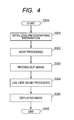
FIG. 4 is a flowchart illustrating a live-view display operation. -
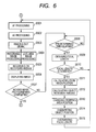
FIG. 5 is a flowchart of operations and a processing procedure used by an image pickup apparatus to perform zooming in a moving image photographing mode. -
FIG. 6 is a flowchart of operations and a processing procedure used by the image pickup apparatus to perform zooming in the moving image photographing mode. -
FIG. 7A, FIG. 7B and FIG. 7C are diagrams illustrating live view images obtained before and after zooming according to a first embodiment of the present invention. -
FIGS. 8A and 8B are diagrams illustrating photographed images corresponding to a photographing area of an image pickup element if live view photographing is performed using a zoom function based on an optical lens in accordance with the prior art. - Embodiments of the present invention will now be described in detail in accordance with the accompanying drawings.
- First Embodiment
- A first embodiment of the present invention will be described with reference to
FIG. 1 to FIG. 7 . -
FIG. 1 is a block diagram illustrating the internal configuration of a single lens reflex digital camera according to embodiments of the present invention. - As shown in
FIG. 1 , the single lens reflex digital camera according to the present embodiment includes an electronic cameramain body 100 forming a single lens digital camera main body, a photographinglens unit 300 including a photographing optical system with a plurality of photographinglenses 310, arecording medium 200 and apower source unit 86. Furthermore, therecording medium 200 and thepower source unit 86 are detachably mounted in the electronic cameramain body 100. - The photographing
lens unit 300 includes a driving section configured to drive the photographinglens 310 and a light amount limitation unit configured to adjust the amount of incident light transmitted through the photographinglens 310. Furthermore, the photographinglens unit 300 is detachably disposed in the electronic cameramain body 100. - Additionally, the electronic camera
main body 100 is configured as follows. - A
shutter 12 controls the exposure amount of theimage pickup element 14. Animage pickup element 14 converts an optical image into an electric signal and is, for example, a CCD sensor or a CMOS sensor. Light incident on the photographinglens 310 is guided via aniris 316 corresponding to the light amount limitation unit, lens mounts 306 and 106, amirror 112 and theshutter 12. The light is then formed into an optical image on an image pickup plane of theimage pickup element 14. - Furthermore, light incident on the photographing
lens 310 viamirrors optical viewfinder 110. In the description below, themirror 112 is a quick return mirror but may be configured as a half mirror. - An A/
D converter 16 converts an analog signal output from theimage pickup element 14 into a digital signal (hereinafter referred to as image data). - A
timing generation circuit 18 supplies clock signals and control signals to theimage pickup element 14, the A/D converter 16 and a D/A converter 26. Thetiming generation circuit 18 is controlled by amemory control circuit 22 and asystem control circuit 50. - An
image processing circuit 20 carries out a predetermined pixel interpolation process and a predetermined color conversion process on one of image data from the A/D converter 16 and image data from thememory control circuit 22. Furthermore, theimage processing circuit 20 uses image data to carry out predetermined arithmetic processing as required. Based on arithmetic processing results obtained, thesystem control circuit 50 carries out AF (Auto Focus) processing based on a TTL (Through The Lens) method, AE (Automatic Exposure control) processing and EF (strobe flash adjustment) processing to control a focus adjustment unit 42 (hereinafter referred to as a distance measurement unit) and aphotometry unit 44. Moreover, theimage processing circuit 20 is configured to carry out a WB (White Balance) process. - The
memory control circuit 22 controls the A/D converter 16, thetiming generation circuit 18, theimage processing circuit 20, theimage display memory 24, the D/A converter 26, amemory 30, and a compression/expansion circuit 32. The image data output by the A/D converter 16 is written to one of theimage display memory 24 and thememory 30 via theimage processing circuit 20 andmemory control circuit 22 or only via thememory control circuit 22. - The
image display memory 24, the D/A converter 26 and an image display section 28 (for example, a TFT or an LCD) carries out processing required for image display. Specifically, display image data written to theimage display memory 24 is output to theimage display section 28 via the D/A converter 26 for display. When image data picked up by theimage pickup element 14 is sequentially displayed using theimage display section 28, live-view display (a finder function provided before and after photographing to display moving images picked up by the image pickup element 14) can be realized. Alternatively, the image data recorded in arecording area 202 of therecording medium 200 may be read, subjected to predetermined processing by the compression/expansion circuit 32, and then displayed on theimage display section 28 via theimage display memory 24 and the D/A converter 26. - The
memory 30 is a storage medium in which photographed still and moving images are stored. Thememory 30 has a storage capacity sufficient to store a predetermined number of still images and a predetermined time of moving images. Thus, even in continuous photographing in which a plurality of still images is continuously photographed, a large amount of images can be written to thememory 30 at a high speed. Furthermore, thememory 30 can be used as a work area for thesystem control circuit 50. - The compression/
expansion circuit 32 compresses and expands image data by adaptive discrete cosine transform (ADCT). The compression/expansion circuit 32 reads the image data stored in thememory 30, carries out one of a compression process and an expansion process on the image data, and then writes the processed image data to thememory 30. - The
shutter control circuit 40 cooperates with aniris control circuit 330 configured to control theiris 316, to control theshutter 12 on the basis of photometry information from thephotometry unit 44. Thedistance measurement unit 42 carries out AF (AutoFocus) processing. That is, thedistance measurement unit 42 forms light incident on the photographinglens 310 into an optical image on an AF sensor (not shown in the drawings) in thedistance measurement unit 42 via theiris 316, the lens mounts 306 and 106, themirror 112 and distance measurement submirror (not shown in the drawings), thus measuring the in-focus state of images. - The
photometry unit 44 is a photometry apparatus configured to carry out an AE (AutoExposure) process. Thephotometry unit 44 forms light incident on the photographinglens 310 into an optical image on a photometry sensor (not shown in the drawings) in thephotometry unit 44 via theiris 316, the lens mounts 306 and 106, themirror 112 and a photometry lens (not shown in the drawings), thus measuring the exposure state of images. - The
photometry unit 44 is configured to be able to also carry out AF processing and AE processing using a contrast AF method in which thesystem control circuit 50 controls theshutter control circuit 40, theiris control circuit 330 and the distancemeasurement control circuit 332 on the basis of the results of calculation, by theimage processing circuit 20, of image data picked up by theimage pickup element 14. - The
system control circuit 50 controls the whole electronic cameramain body 100. Amemory 72 is configured to store constants, variables, programs and the like which are used to operate thesystem control circuit 50. Thesystem control circuit 50 is used as a determination unit and a control unit in various operations of the electronic cameramain body 100. - A cropping
area setting unit 52 is provided in thesystem control circuit 50 to store the size of a cropping area set by the photographer using theoperation section 70, in a croppingarea storing unit 94. Furthermore, based on a change in the focal length of the photographinglens 310, the croppingarea setting unit 52 changes the size and position of the cropping area and stores the changed size and position in the croppingarea storing unit 94. - A focal length
change determination unit 54 is provided in thesystem control circuit 50. The focal lengthchange determination unit 54 compares the focal length stored in a focallength storing unit 98 with the current focal length of the photographinglens 310 obtained by alens communication unit 124 to determine whether or not the focal length has been changed. - A
mode dial 60, a release switch SW1 (62) and a release switch SW2 (64) are an operation unit configured to input various operation instructions for thesystem control circuit 50. Each of the dial and switches includes a combination of one or more of a switch, a dial, a touch panel, pointing based on viewpoint detection, an audio recognition apparatus, and the like. - Now, these operation units will be specifically described. The
mode dial 60 is a rotary switch that enables switching and setting of functional photographing modes such as an auto-photographing mode, a program photographing mode, a shutter-priority photographing mode, an iris-priority photographing mode, a manual photographing mode, a still image photographing mode, and a moving image photographing mode. - The release switch SW1 (62) is turned on during operation of a release button (not shown in the drawings) to give an instruction to start an operation for one of AF (AutoFocus) processing, AE (AutoExposure) processing, WB (White Balance) processing, and EF (strobe flash adjustment) processing. The release switch SW2 (64) is turned on when operation of the release button (not shown in the drawings) is complete to give an instruction to start an operation for a series of processes including an exposure process of reading a signal from the
image pickup element 14 and writing corresponding image data to thememory 30 via the A/D converter 16 and thememory control circuit 22, a development process using calculations in theimage processing circuit 20 and thememory control circuit 22, and a recording process of reading the image data from thememory 30, allowing the compression/expansion circuit 32 to compress the image data, and writing the compressed image data to therecording medium 200. - An
image display button 66 can be used to set theimage display section 28 to be turned on and off. When images are photographed using theoptical viewfinder 110, this function can be used to interrupt the supply of current to theimage display section 28, including an LCD, thus saving power. - A moving
image photographing button 68 allows moving image photographing to be started when turned on for the first time and allows the moving image photographing to be ended when turned on for the second time. - An
operation section 70 includes the various buttons and the touch panel. Theoperation section 70 includes, for example, a menu button, a set button, a multi-screen reproduction page feed button, a flash setting button, a single photographing/continuous photographing/self timer switching button, a menu selection + (plus) button, a menu selection - (minus) button, a photographing image quality selection button, an exposure correction button, a date/time setting button and an enter/execution button. - The selection/switching button is used to set selection and switching of various functions to be performed in order to carry out photographing and reproduction. The enter/execution button is used to set the various functions to be entered and executed in order to carry out photographing and reproduction.
- To set the size of the cropping area, the photographer uses a cropping area setting menu so as to operate the plus button, minus button and enter/execution button on the
operation section 70 to determine the size of the cropping area. For example, one of a plurality of preset cropping area sizes may be selected and decided. - The
memory 72 is configured to store constants, variables, programs, and the like for the operation of thesystem control circuit 50. - A
display section 74 has a display function provided in, for example, a liquid crystal display to display an operational state and messages using characters, images, and audio messages in response to execution of the appropriate program by thesystem control circuit 50, and a sound generation function provided in, for example, speakers to generate operation sounds and warning sounds in response to execution of the appropriate program by thesystem control circuit 50. One ormore display sections 74 are installed at an easily visually recognizable position close to the operation section of the electronic cameramain body 100. Thedisplay section 74 includes, for example, a combination of an LCD, an LED and a sound generation element. - A
nonvolatile memory 76 is an electrically erasable and recordable memory, and the contents of thememory 72 are recorded in thenonvolatile memory 76 as required. For example, an EEPROM is used as thenonvolatile memory 76. - A
timer 78 measures elapsed time. - A power
source control circuit 80 includes a battery detection circuit, a DC-DC converter, and a switch circuit configured to switch a block to be energized. The powersource control circuit 80 detects the type of a battery and the remaining battery charge to control the DC-DC converter based on the results of the detections and instructions from thesystem control circuit 50. The powersource control circuit 80 supplies each of the sections including the recording medium with the required voltage for a required period.Connectors main body 100 to thepower source unit 86. Thepower source unit 86 includes a primary battery such as an alkaline battery or a lithium battery, a secondary battery such as a NiCd battery, an NiMH battery, or an Li battery, and an AC adapter. - A
power source switch 88 enables the power-on and power-off modes of the electronic cameramain body 100 to be switched and set. Furthermore, power source switch 88 also enables various accessory devices such as the photographinglens unit 300 connected to the electronic cameramain body 100, an external strobe (not shown in the drawings) and therecording medium 200 to be powered on and off. - An
interface 90 is used for a recording medium such as a memory card or a hard disk. Aconnector 92 is connected to the recording medium such as a memory card or a hard disk. - The cropping
area storing unit 94 is configured to store the size and position of the cropping area set by the croppingarea setting unit 52 in thesystem control circuit 50. - An object
position storing unit 96 is configured to store an in-focus position resulting from AF processing carried out by thedistance measurement unit 42 or contrast AF, as an object position. Furthermore, the objectposition storing unit 96 is configured to store the object position in a live-view image, obtained based on the in-focus position and an object movement amount calculated by thesystem control circuit 50. - The focal
length storing unit 98 is configured to store the focal length obtained by the photographinglens communication unit 124 through communication. - A
lens communication interface 120 is provided in thelens mount 106 to allow the electronic cameramain body 100 to be connected to the photographinglens unit 300. Alens communication connector 122 is used to electrically connect the electronic cameramain body 100 to the photographinglens unit 300. The photographinglens communication unit 124 includes thelens communication interface 120 and thelens communication connector 122. - The
lens communication connector 122 transmits control signals, status signals, data signals, and the like between the electronic cameramain body 100 and the photographinglens unit 300. Thelens communication connector 122 also has a function of supplying currents with various voltages. Furthermore, theconnector 122 may be configured to transmit not only electric communication but also optical communication and audio communication. - The
recording medium 200 is a memory card or a hard disk. Therecording medium 200 includes therecording area 202 formed of a semiconductor memory, a magnetic disk, or the like, aninterface 204 to the electronic cameramain body 100 and a connector 206 connected to the electronic cameramain body 100. Image data is recorded in therecording area 202. Furthermore, image pickup information is recorded in therecording medium 200 in association with image data, as image pickup information data. - Now, the above-described photographing
lens unit 300 will be described in further detail. The photographinglens unit 300 is of a replacement lens type as described above. - The
lens mount 306 allows the photographinglens unit 300 to be mechanically coupled to the electronic cameramain body 100. Thelens mount 306 contains various functions allowing the photographinglens unit 300 to be electrically connected to the electronic cameramain body 100. - The photographing
lens 310 includes azoom lens 312 and afocus lens 314. Thezoom lens 312 is controlled by a zoomlens control unit 334 so as to have the position thereof moved in a photographing optical axis direction to enable zooming. The zooming allows a change in the angle of view for image pickup carried out by theimage pickup element 14. - The
focus lens 314 is controlled by a focuslens control unit 332 so as to have the position thereof moved in the photographing optical axis direction to enable the focus of the photographinglens 310 to be adjusted. - An
interface 320 is provided in thelens mount 306 to connect the photographinglens unit 300 to the electronic cameramain body 100. Aconnector 322 is used to electrically connect the photographinglens unit 300 to the electronic cameramain body 100. Theconnector 322 transmits control signals, status signals, data signals and the like between the electronic cameramain body 100 and thelens unit 300. Theconnector 322 also has a function of receiving or supplying currents with various voltages. - The
iris control circuit 330 cooperates with theshutter control circuit 40 configured to control theshutter 12, in controlling theiris 316 based on photometry information from thephotometry unit 44. The focuslens control circuit 332 moves the position of thefocus lens 314 to control the adjustment of focus of the photographinglens 310. - The zoom
lens control unit 334 moves the position of thezoom lens 312 to control the zooming of the photographinglens 310. The lenssystem control circuit 336 controls the whole photographinglens unit 300. The lenssystem control circuit 336 also has the functions of the memory in which the constants, variables, programs and the like for operations are stored and the functions of the nonvolatile memory configured to hold identification information such as the unique number of the photographinglens unit 300, management information, function information such as an open iris value, a minimum iris value and the focal length, the current and past set values, and the like. In response to an instruction from the electronic cameramain body 100, the lenssystem control circuit 336 transmits the function information to the electronic cameramain body 100 via theinterface 320 and theconnector 322. - Now, with reference to
FIG. 2 to FIG. 4 andFIG. 7 , an operation will be described which is performed if zooming is carried out during live-view display in the still image photographing mode, which corresponds to a first embodiment of the present invention. -
FIG. 2 andFIG. 3 are flowcharts illustrating operations and a processing procedure used by the image pickup apparatus to perform zooming during live-view display in the still image photographing mode, which corresponds to a first embodiment of the present invention. - As illustrated in
FIG. 2 , when the processing is started, thesystem control circuit 50 determines whether or not the current photographing mode is cropping photographing mode (step S101). If the current photographing mode is not cropping photographing mode (NO in step S101), the determination for the cropping photographing mode is repeated. At this time, the live-view display is in a normal photographing mode. The present invention relates to cropping photographing. Thus, the description of normal photographing is omitted. - In step S101, if the current photographing mode is determined to be in the cropping photographing mode (YES in step S101), the
system control circuit 50 determines whether or not the size of the cropping area has been set by the croppingarea setting unit 52 and stored in the cropping area storing unit 94 (step S102). - If the size of the cropping area has not been set or stored in the cropping area storing unit 94 (NO in step S102), the
system control circuit 50 notifies the photographer using thedisplay section 74 that the cropping area has not been set, to prompt the photographer to set the size of the cropping area using theoperation section 70. The set size of the cropping area is stored in the cropping area storing unit 94 (step S103). - In step S102, if the size of the cropping area has been set (YES in step S102), the
system control circuit 50 resets the position of the cropping area stored in the croppingarea storing unit 94 and initializes the position to the origin (the center of a photographing screen) (step S104). - Subsequently, the
system control circuit 50 determines whether or not theimage display button 66 has been turned on (step S105). If theimage display button 66 has been turned off (NO in step S105), thesystem control circuit 50 repeats the operation of determining whether or not theimage display button 66 has been turned on. - In step S105, if the
image display button 66 has been turned on (YES in step S105), thesystem control circuit 50 withdraws up the mirror 112 (step S106) and then uses theimage display section 28 to provide live-view display (step S107). Thesystem control circuit 50 resets thetimer 78 to "0" and then starts the timer (step S108). - Now, a live-view display operation will be described with reference to the flowchart in
FIG. 4. FIG. 4 is a flowchart illustrating a live-view display operation. - First, the
system control circuit 50 carries out initialization for photographing preparation to allow live-view images to be displayed on the image display section 28 (step S301). - In single lens reflex digital cameras, the
image pickup element 14 is generally shielded from light by themirror 112 and theshutter 12 except during exposure. Thus, for AF and AE, theimage pickup element 14 is not used but an AF sensor and an AE sensor for a particular application are separately disposed to receive light which is incident via the photographinglens 310 and which is then divided into optical paths. - However, for live-view display, the
mirror 112 is flipped up to open theshutter 12 to bring theimage pickup element 14 into an exposure state. In this state, light is prevented from reaching the AF sensor in thedistance measurement unit 42 and the AE sensor in thephotometry unit 44. Thus, the sensors will fail to carry out AF and AE. Hence, the contrast AF and image pickup plane AE functions are used in order to carry out AF and AE during live-view display (step S302). - The
system control circuit 50 controls thetiming generation circuit 18 to allow an analog signal to be read from theimage pickup element 14 at a frame rate timing for live-view display (step S303). The analog signal read from theimage pickup element 14 is converted into a digital signal by the A/D converter 16. The digital signal is then subjected to image processing for live-view display by theimage processing circuit 20 and thememory control circuit 22. The resultant image data is stored in the image display memory 24 (step S304). The image data stored in theimage display memory 24 is then displayed on theimage display section 28 via thememory control circuit 22 and the D/A converter 26 (step S305). The operations in step S302 to step S305 are sequentially repeated to implement live-view display. - In step S109 in
FIG. 2 , the in-focus position resulting from the contrast AF in step S302 inFIG. 4 is defined as an object position and stored in the object position storing unit 96 (step S109). - Then, the
system control circuit 50 communicates with the photographinglens unit 300 via thelens communication interface 120 andlens communication connector 122, corresponding to the photographinglens communication unit 124, to obtain the current focal length of the photographing lens 310 (step S110) Thesystem control circuit 50 stores the current focal length in the focal length storing unit 98 (step S111). - Subsequently, the
system control circuit 50 determines whether or not the release switch SW1 (62) has been turned on (step S112). If the release switch SW1 (62) has been turned on (YES in step S112), thesystem control circuit 50 proceeds to step S200 inFIG. 3 . - If the release switch SW1 (62) has been turned off (NO in step S112), the
system control circuit 50 determines whether or not the elapsed time in thetimer 78 has reached a preset predetermined time (t) (step S113). The predetermined time (t) is based on the frame rate for the live-view display and is about 0.03 second if the frame rate is 30 fps. - If the elapsed time in the
timer 78 has not reached the predetermined time (t) (NO in step S113), the determination operation is repeated until the predetermined time (t) is reached. - If the elapsed time in the
timer 78 has reached the predetermined time (t) (YES in step S113), thesystem control circuit 50 communicates with the photographinglens unit 300 to obtain the current focal length of the photographinglens 310 again (step S114). The focal lengthchange determination unit 54 determines whether or not the focal length obtained is different from the focal length stored in the focal length storing unit 98 (step S115). - If the two focal lengths are the same (NO in step S115), this means that zooming has not been carried out. The
system control circuit 50 thus provides live-view display again (step S116) and proceeds to step S112. If the two focal lengths are different (YES in step S115), this means that zooming has changed the angle of view. Thus, thesystem control circuit 50 calculates a zoom magnification from those two focal lengths (step S117). - Subsequently, the
system control circuit 50 calculates the object movement amount in the image pickup plane of theimage pickup element 14 from the zoom magnification calculated in step S117 and the object position stored in the object position storing unit 96 (step S118). The croppingarea setting unit 52 sets the position of the cropping area on the basis of the calculated object movement amount and changes the position of the cropping area stored in the cropping area storing unit 94 (step S119). That is, the image pickup apparatus (100) according to the present invention includes the control unit (50) operating in accordance with the cropping photographing mode in the following manner. The control unit controls the lens information obtaining unit to allow the current focal length of the photographing lens to be obtained. The control unit further controls setting, by the cropping area setting unit, of the position of the cropping area on the basis of the focal length stored in the focal length storing unit, the current focal length and the object position stored in the object position storing unit. In this configuration, when zooming is performed using the optical lens, the position of the cropping area can be changed depending on the zoom magnification to provide live-view display without displacing the object out of the displayed image during the zooming. - Moreover, the
system control circuit 50 calculates the object position in the live-view image from the object movement amount calculated in step S118. Thesystem control circuit 50 overwrites the object position stored in the objectposition storing unit 96, with the calculated object position, which is thus stored in the object position storing unit 96 (step S120). Furthermore, the focal length stored in the focallength storing unit 98 is overwritten with the focal length of the photographinglens 310 obtained in step S113, which is thus stored in the focal length storing unit 98 (step S121). - Then, based on the position of the cropping area set in step S119, the
system control circuit 50 provides live-view display (step S122) and then determines whether or not theimage display button 66 has been turned on (step S123). If theimage display button 66 has been turned on (YES in step S123), thesystem control circuit 50 returns to step S112. If theimage display button 66 has been turned off (NO in step S123), thesystem control circuit 50 withdraws down the mirror 112 (step S124) and ends the live view operation (step S125). - In step S112 in
FIG. 2 , if the release switch SW1 (62) has been turned on (YES in step S112), thesystem control circuit 50 determines whether or not the release switch SW2 (64) has been turned on (step S200 inFIG. 3 ). If the release switch SW2 (64) has not been turned on (NO in step S200), thesystem control circuit 50 proceeds to step S212. - In step S200 in
FIG. 3 , if the release switch SW2 (64) has been turned on (YES in step S200), thesystem control circuit 50 withdraws down the mirror 112 (step S201). When themirror 112 is withdrawn down, object light is incident on the AF sensor in thedistance measurement unit 42 and the AE sensor in thephotometry unit 44; the AF and AE sensors are exposed to the object light. Thus, signal charges are accumulated in the sensors for a predetermined time. After the accumulation, thesystem control circuit 50 reads an analog signal output for the accumulated signal charges from each of the sensors. Thesystem control circuit 50 then carries out AF (AutoFocus) processing and AE (AutoExposure) processing (step S202). Then, photographing is performed (step S203). - Then, the
system control circuit 50 controls thetiming generation circuit 18 to allow an analog signal to be read from theimage pickup element 14. The A/D converter 16 converts the analog signal into a digital signal. Thesystem control circuit 50 then stores the digital signal in the image memory 30 (step S204). - Two image data, image data to be recorded in the
recording medium 200 and image data for live-view display are created from the image data stored in theimage memory 30. The image data to be recorded in therecording medium 200 is subjected to a predetermined development process and a predetermined compression process by theimage processing circuit 20 in accordance with a JPEG method. The processed image data is stored in theimage memory 30 again. Furthermore, the image data for live-view display is subjected to image processing such as a predetermined development process, a predetermined pixel thinning-out process and a predetermined compression process on the basis of the number of pixels in theimage display section 28. The processed image data is stored in the image display memory 24 (step S205). - The image data to be recorded in the
recording medium 200 which has been stored in theimage memory 30 is written to and recorded in therecording area 202 of the recording medium 200 (step S206). - Furthermore, the image data for live-view display stored in the
image display memory 24 is displayed on theimage display section 28 via thememory control circuit 22 and the D/A converter 26 (step S207). - The
system control circuit 50 specifies the in-focus position resulting from the AF (AutoFocus) processing in step S202, as an object position. Thesystem control circuit 50 then overwrites the object position stored in the objectposition storing unit 96 with the specified object position, which is then stored in the object position storing unit 96 (step S208). - Then, the
system control circuit 50 determines whether or not theimage display button 66 has been turned on (step S209). If theimage display button 66 has been turned off (NO in step S209), thesystem control circuit 50 ends the processing (step S210). If theimage display button 66 has been turned on (YES in step S209), thesystem control circuit 50 withdraws up the mirror 112 (step S211) and then proceeds to step S112 inFIG. 2 . - Step S212 to step S225 in
FIG. 3 involve the same operations as those in step S112 to step S125 inFIG. 2 and will thus not be described below. - As described above, the image pickup apparatus according to the present invention is configured as follows. The focal length change determination unit (54) compares the focal length stored in the focal length storing unit with the current focal length to determine whether or not the focal length of the photographing lens (310) has been changed. If the focal length change determination unit (54) determines that the focal length of the photographing lens (310) has not been changed, the cropping area setting unit is controlled so as not to change the setting of the size and position of the cropping area. If the focal length change determination unit (54) determines that the focal length of the photographing lens (310) has been changed, the cropping area setting unit is controlled so as to change the position of the cropping area on the basis of the focal length stored in the focal length storing unit, the current focal length and the object position stored in the object position storing unit.
-
FIG. 7A, FIG. 7B and FIG. 7C are diagrams illustrating the position of the cropping area in live-view display according to the first embodiment of the present invention. -
FIG. 7A is a diagram illustrating the cropping area obtained before zooming. A photographing enabled area of theimage pickup element 14 is illustrated at 400. The cropping area obtained before the zooming is illustrated at 410. The in-focus position resulting from the contrast AF in step S302 inFIG. 4 is illustrated at 412. -
FIG. 7B is a diagram illustrating the position of the cropping area obtained after the zooming. The cropping area obtained after zooming is illustrated at 420. The object position in the image pickup plane moves concurrently with the zooming. The position of the cropping area changes from 410 to 420 based on the object movement amount calculated in step S118 inFIG. 2 . -
FIG. 7C is a diagram illustrating the relationship between the position of cropping area before the zooming and the position of the cropping area after the zooming. When the cropping area is shifted from 410 to 420 as illustrated inFIG. 7B , the object position in the live-view image is prevented from being moved and remains at 412 in spite of the zooming. - As described above, the image pickup apparatus according to the first embodiment of the present invention includes the photographing lens (310) with the zoom function, the lens information obtaining unit (124) configured to obtain information on the photographing lens (310), and the image pickup element (14) configured to photoelectrically convert the object image formed on the image pickup plane by the image pickup lens (310), into an image signal. The image pickup apparatus also includes the cropping photographing mode in which the cropping area is set in a part of the image pickup plane of the image pickup element (14) so that an image signal is read from the cropping area to generate image data. In the cropping photographing mode, the image data is displayed in accordance with the size and position of the cropping area set in the cropping area setting unit under the control of the above-described control unit. Thus, live-view display can be provided without failing to place the object within the displayed image area in spite of zooming. Moreover, the position of the object in the live-view display image is prevented from being moved in spite of the zooming. Hence, the appropriate live-view display can be provided without the need for framing performed by the photographer. Furthermore, since the photographer need not perform framing, even if in remotely-operated photographing using a tripod, zooming is performed using the optical lens, live-view display can be provided without failing to place the object within the photographing area.
- Second Embodiment
- A second embodiment of the present invention will be described with reference to
FIG. 5 andFIG. 6 . -
FIG. 5 andFIG. 6 are flowcharts illustrating operations and a processing procedure used by an image pickup apparatus to perform zooming in a moving image photographing mode corresponding to an embodiment of the present invention. - Step S401 to step S411 in
FIG. 5 involve the same operations as those in step S101 to step S111 inFIG. 2 and will thus not be described below. - In step S412, a
system control circuit 50 determines whether or not a movingimage photographing button 68 has been turned on to start moving image photographing (step S412). If the movingimage photographing button 68 has been turned on to start the moving image photographing (YES in step S412), thesystem control circuit 50 proceeds to step S500 inFIG. 6 . - If the moving
image photographing button 68 has not been turned on and thus the moving image photographing has not been started (NO in step S412), thesystem control circuit 50 proceeds to step S413. - Step S413 to step S425 involve the same operations as those in step S113 to step S125 in
FIG. 2 and will thus not be described below. - In step S412 in
FIG. 5 , if the movingimage photographing button 68 has been turned on to start the moving image photographing (YES in step S412), animage processing circuit 20 carries out a predetermined distance measurement calculation on a signal obtained from theimage pickup element 14. Theimage processing circuit 20 stores the result of the calculation in amemory 30. Based on the calculation result, thesystem control circuit 50 uses thedistance measurement unit 42 to carry out AF processing (step S501). - Subsequently, the
image processing circuit 20 carries out a predetermined photometry calculation on a signal obtained from theimage pickup element 14. Theimage processing circuit 20 stores the result of the calculation in asystem memory 32. Thesystem control circuit 50 carries out an AE process on the basis of the calculation result (step S502). - Then, a moving image process in a series of photographing operations is carried out. The
system control circuit 50 controls atiming generation circuit 18 to allow an analog signal to be read from theimage pickup element 14. An A/D converter 16 converts the analog signal into a digital signal, which is then stored in the image memory 30 (step S503). - Two image data, image data to be recorded in a
recording medium 200 and image data for live-view display are created from the image data stored in theimage memory 30 in step S503. The image data to be recorded in therecording medium 200 is subjected to a predetermined development process and a predetermined compression process by theimage processing circuit 20 in accordance with the JPEG method. The processed image data is stored in theimage memory 30 again. Furthermore, the image data for live-view display is subjected to image processing such as a predetermined development process, a predetermined pixel decimation process and a predetermined compression process on the basis of the number of pixels in animage display section 28. The processed image data is stored in an image display memory 24 (step S504). - The image data to be recorded in the
recording medium 200 which has been stored in theimage memory 30 is written to and recorded in arecording area 202 of therecording medium 200 as the first frame of a moving image file (step S505). - Furthermore, the image data for live-view display stored in the
image display memory 24 is displayed on theimage display section 28 via amemory control circuit 22 and a D/A converter 26 (step S506). - Then, the
system control circuit 50 determines whether or not the movingimage photographing button 68 has been turned on again to end the moving image photographing (step S507). - If the moving
image photographing button 68 has been turned on again to end the moving image photographing (YES in step S507), thesystem control circuit 50 proceeds to step S413 inFIG. 5 . - In step S507, if the moving
image photographing button 68 has not been turned on again and the moving image photographing is continued (NO in step S507), thesystem control circuit 50 determines whether or not the elapsed time in atimer 78 has reached a preset predetermined time (t) (step S508). - If the elapsed time in a
timer 78 has not reached the preset predetermined time (t) (NO in step S508), thesystem control circuit 50 repeats the determination operation until the predetermined time (t) is reached. - If the elapsed time in a
timer 78 has reached the preset predetermined time (t) (YES in step S508), thesystem control circuit 50 communicates with a photographinglens unit 300 to obtain the current focal length of a photographing lens 310 (step S509). Thesystem control circuit 50 then determines whether or not the current focal length is different from the focal length stored in a focal length storing unit 98 (step S510). - If the two focal lengths are the same (NO in step S510), this means that zooming has not been carried out. The
system control circuit 50 thus proceeds to step S501. - If the two focal lengths are different (YES in step S510), this means that zooming has been carried out. Thus, the
system control circuit 50 proceeds to step S511. - Step S511 to step S515 following the above-described steps involve the same operations as those in step S112 to step S121 in
FIG. 2 and will thus not be described below. - In step S515, the focal length stored in the focal
length storing unit 98 is overwritten with the focal length of the photographinglens 310, which is thus stored in the focallength storing unit 98. Thesystem control circuit 50 then proceeds to step S501. - As described above, the image pickup apparatus according to the second embodiment of the present invention includes the moving image photographing mode in which moving images are photographed and recorded. In photographing in the moving image photographing mode, the control unit can control setting of the position of the cropping area in accordance with the cropping photographing mode. That is, the focal length change determination unit (54) compares the focal length stored in the focal length storing unit with the current focal length to determine whether or not the focal length of the photographing lens (310) has been changed. If the focal length change determination unit (54) determines that the focal length of the photographing lens (310) has not been changed, the control unit controls the cropping area setting unit so that the cropping area setting unit does not change the set size and position of the cropping area. If the focal length change determination unit determines that the focal length of the photographing lens has been changed, the control unit controls the cropping area setting unit so that the cropping area setting unit changes the position of the cropping area on the basis of the focal length stored in the focal length storing unit, the current focal length and the object position stored in the object position storing unit. Thus, even if in photographing in the moving image photographing mode, zooming is performed using the optical system photographing lens, since the position of the cropping area is changed depending on the zoom magnification, live-view display and moving image photographing can be achieved without failing to place the object within the photographed image in spite of the optical zooming. Furthermore, the object position is prevented from being moved in the moving image during the optical zooming. Thus, the live-view display of photographed image of the object and the moving image photographing can be easily achieved without a framing operation performed by the photographer. Moreover, even if remotely-operated photographing is performed with the image pickup apparatus fixed with a tripod or the like, the live-view display and the moving image photographing can be achieved without the need for framing, which prevents the object from being displaced out of the photographing area.
- The present invention has been described in detail based on the embodiments thereof. However, the present invention is not limited to these particular embodiments but encompasses various aspects without departing from the spirits thereof. The above-described embodiments may be appropriately partly combined with one another.
- Furthermore, in the description of the first and second embodiments, the image pickup apparatus is a single lens reflex digital camera with the detachably mounted electronic camera
main body 100 and photographinglens unit 300. However, the photographinglens 310 may be included in the electronic cameramain body 100. - Furthermore, in the configuration of the present invention described above, the control by the
system control circuit 50 may be performed by one piece of hardware or the relevant processing may be shared by plural pieces of hardware so as to achieve the control of the whole apparatus. - The present invention is implemented by carrying out the following processing. Software (computer program) configured to implement the functions of the above-described embodiments is supplied to one of a system and an apparatus via one of a network (communication) and any of various computer-readable recording media. A computer (or a CPU or an MPU) in one of the system and the apparatus reads and executes a program code. In this case, the software and a recording medium in which the software is recorded as the computer program code form the present invention.
- The above-described embodiments are only typical examples. In practice, many variations and changes may be made to the present embodiments.
- While the present invention has been described with reference to embodiments, it is to be understood that the invention is not limited to the disclosed embodiments.
-
- 1. An image pickup apparatus comprising a photographing lens with a zoom function and an image pickup means arranged to photoelectrically convert an object image formed on an image pickup plane by the photographing lens into an image signal,
characterized by
lens information obtaining means arranged to obtain information on the photographing lens;
cropping area setting means arranged to set a size and a position of a cropping area;
object position storing means arranged to detect and store the object position in the image pickup plane on the basis of the image signal;
focal length storing means arranged to store the focal length of the photographing lens obtained by the lens information obtaining means;
control means arranged to control the lens information obtaining means to enable the current focal length of the photographing lens to be obtained and to control setting of the position of the cropping area by the cropping area setting means on the basis of the focal length stored by the focal length storing means, the current focal length and the object position stored in the object position storing means; and
display means arranged to display image data in accordance with the size and position of the cropping area which is set by the cropping area setting means under control of the control means. - 2. The image pickup apparatus according to
statement 1, further comprising focal length change determination means arranged to compare the focal length stored in the focal length storing means, with the current focal length to determine whether or not the focal length of the photographing lens has been changed,
wherein the control means is arranged to perform first control if the focal length change determination means determines that the focal length of the photographing lens has not been changed, and performs second control if the focal length change determination means determines that the focal length of the photographing lens has been changed,
wherein in the first control, the controller is arranged to control the cropping area setting means in such a manner that the cropping area setting means does not change the size and position of the cropping area, and
wherein in the second control, the control means is arranged to control the cropping area setting means in such a manner that the cropping area setting means changes the position of the cropping area on the basis of the focal length stored in the focal length storing means , the current focal length and the object position stored in the object position storing means. - 3. The image pickup apparatus according to statement 2, wherein in the second control, the focal length storing means is controlled so as to store the current focal length, and the object position storing means is controlled so as to change the object position stored in the object position storing means in accordance with the changed position of the cropping area and to store the changed object position.
- 4. The image pickup apparatus according to
statement 1, wherein the controller is arranged to control the lens information obtaining means to enable the current focal length to be obtained at predetermined times, thus controlling setting of the position of the cropping area. - 5. The image pickup apparatus according to
statement 1, wherein if a cropping photographing mode is set, the controller is arranged to control the cropping area setting means to enable the set position of the cropping area to be initialized. - 6. The image pickup apparatus according to
statement 1, wherein the image pickup apparatus has a moving image photographing mode in which a moving image is photographed and recorded, and wherein the controller is arranged to control setting of the position of the cropping area in the moving image photographing mode. - 7. A control method of an image pickup apparatus including a photographing lens with a zoom function and image pickup means for photoelectrically converting an object image formed on an image pickup plane by the photographing lens to generate an image signal,
the method being characterized by,
obtaining information on the photographing lens with the zoom function;
setting a size and a position of a cropping area; detecting and storing the object position in the image pickup plane on the basis of the image signal;
storing a focal length of the photographing lens obtained in the lens information obtaining step;
controlling the lens information obtaining step to allow the current focal length of the photographing lens to be obtained and to control setting of the position of the cropping area carried out in the cropping area setting step on the basis of the focal length stored in the focal length storing step, the current focal length and the object position stored in the object position storing step; and
displaying the image data in accordance with the size and position of the cropping area which is set in the cropping area setting step under control of the control unit. - 8. A computer program for causing a computer to function as the apparatus recited in any one of
statements 1 to 6. - 9. A computer-readable recording medium storing the computer program according to statement 8.
Claims (9)
- An image pickup apparatus comprising a photographing lens with a zoom function and an image pickup means arranged to photoelectrically convert an object image formed on an image pickup plane by the photographing lens into an image signal,
characterized by
lens information obtaining means arranged to obtain information on the photographing lens;
object position storing means arranged to detect and store the object position in the image pickup plane on the basis of the image signal;
focal length storing means arranged to store the focal length of the photographing lens obtained by the lens information obtaining means; and
control means arranged to control a display means to display a cropping area, wherein the cropping area is based on the focal length of the photographing lens to be obtained, the focal length stored by the focal length storing means, and the object position stored in the object position storing means. - The image pickup apparatus according to claim 1, further comprising focal length change determination means arranged to compare the focal length stored in the focal length storing means, with the current focal length to determine whether or not the focal length of the photographing lens has been changed,
wherein the control means is arranged to perform first control if the focal length change determination means determines that the focal length of the photographing lens has not been changed, and performs second control if the focal length change determination means determines that the focal length of the photographing lens has been changed,
wherein in the first control, the controller is arranged to control the cropping area setting means in such a manner that the cropping area setting means does not change the size and position of the cropping area, and
wherein in the second control, the control means is arranged to control the cropping area setting means in such a manner that the cropping area setting means changes the position of the cropping area on the basis of the focal length stored in the focal length storing means, the current focal length and the object position stored in the object position storing means. - The image pickup apparatus according to claim 2, wherein in the second control, the focal length storing means is controlled so as to store the current focal length, and the object position storing means is controlled so as to change the object position stored in the object position storing means in accordance with the changed position of the cropping area and to store the changed object position.
- The image pickup apparatus according to claim 1, wherein the controller is arranged to control the lens information obtaining means to enable the current focal length to be obtained at predetermined times, thus controlling setting of the position of the cropping area.
- The image pickup apparatus according to claim 1, wherein if a cropping photographing mode is set, the controller is arranged to control the cropping area setting means to reset the position of the cropping area stored in the cropping area storing unit (94) and initialize the position to the center of a photographing screen (step S102 & S104).
- The image pickup apparatus according to claim 1, wherein the image pickup apparatus has a moving image photographing mode in which a moving image is photographed and recorded, and wherein the controller is arranged to control setting of the position of the cropping area in the moving image photographing mode.
- A control method of an image pickup apparatus including a photographing lens with a zoom function and image pickup means for photoelectrically converting an object image formed on an image pickup plane by the photographing lens to generate an image signal,
the method being characterized by,
obtaining information on the photographing lens with the zoom function;
detecting and storing the object position in the image pickup plane on the basis of the image signal;
storing a focal length of the photographing lens obtained in the lens information obtaining step; and
controlling a display means to display a cropping area, wherein the cropping area is based on the focal length of the photographing lens to be obtained, the focal length stored, and the object position stored. - A computer program for causing an image pickup apparatus to function as the apparatus recited in any one of claims 1 to 6.
- A computer-readable recording medium storing the computer program according to claim 8.
Applications Claiming Priority (2)
| Application Number | Priority Date | Filing Date | Title |
|---|---|---|---|
| JP2009243610A JP5432664B2 (en) | 2009-10-22 | 2009-10-22 | Imaging device |
| EP10188410A EP2323375B1 (en) | 2009-10-22 | 2010-10-21 | Image pickup apparatus |
Related Parent Applications (2)
| Application Number | Title | Priority Date | Filing Date |
|---|---|---|---|
| EP10188410A Division EP2323375B1 (en) | 2009-10-22 | 2010-10-21 | Image pickup apparatus |
| EP10188410.4 Division | 2010-10-21 |
Publications (3)
| Publication Number | Publication Date |
|---|---|
| EP2557772A2 true EP2557772A2 (en) | 2013-02-13 |
| EP2557772A3 EP2557772A3 (en) | 2013-03-27 |
| EP2557772B1 EP2557772B1 (en) | 2014-09-24 |
Family
ID=43513913
Family Applications (2)
| Application Number | Title | Priority Date | Filing Date |
|---|---|---|---|
| EP10188410A Active EP2323375B1 (en) | 2009-10-22 | 2010-10-21 | Image pickup apparatus |
| EP12190541.8A Active EP2557772B1 (en) | 2009-10-22 | 2010-10-21 | Image pickup apparatus |
Family Applications Before (1)
| Application Number | Title | Priority Date | Filing Date |
|---|---|---|---|
| EP10188410A Active EP2323375B1 (en) | 2009-10-22 | 2010-10-21 | Image pickup apparatus |
Country Status (3)
| Country | Link |
|---|---|
| US (1) | US8427556B2 (en) |
| EP (2) | EP2323375B1 (en) |
| JP (1) | JP5432664B2 (en) |
Families Citing this family (7)
| Publication number | Priority date | Publication date | Assignee | Title |
|---|---|---|---|---|
| JP2011166378A (en) * | 2010-02-08 | 2011-08-25 | Canon Inc | Imaging device and control method of the same |
| CN104641275B (en) * | 2012-09-11 | 2017-12-12 | 索尼公司 | The control method that imaging control apparatus, imaging device and imaging control apparatus perform |
| WO2016002447A1 (en) * | 2014-07-03 | 2016-01-07 | ソニー株式会社 | Filter control apparatus, filter control method, and image capture apparatus |
| KR20180018213A (en) * | 2016-08-12 | 2018-02-21 | 삼성전자주식회사 | Electronic device and controlling method thereof |
| CN107392850B (en) | 2017-06-30 | 2020-08-25 | 联想(北京)有限公司 | Image processing method and system |
| CN115379112A (en) * | 2020-09-29 | 2022-11-22 | 华为技术有限公司 | Image processing method and related device |
| CN113630549B (en) * | 2021-06-18 | 2023-07-14 | 北京旷视科技有限公司 | Zoom control method, apparatus, electronic device, and computer-readable storage medium |
Citations (1)
| Publication number | Priority date | Publication date | Assignee | Title |
|---|---|---|---|---|
| JP2005033508A (en) | 2003-07-14 | 2005-02-03 | Minolta Co Ltd | Imaging device |
Family Cites Families (20)
| Publication number | Priority date | Publication date | Assignee | Title |
|---|---|---|---|---|
| US7046290B2 (en) * | 2000-01-26 | 2006-05-16 | Nikon Corporation | Multi-point auto-focus digital camera including electronic zoom |
| JP3894047B2 (en) * | 2002-05-31 | 2007-03-14 | 日本ビクター株式会社 | Surveillance video camera system and imaging method in surveillance video camera system |
| US20040100560A1 (en) * | 2002-11-22 | 2004-05-27 | Stavely Donald J. | Tracking digital zoom in a digital video camera |
| JP2005159856A (en) * | 2003-11-27 | 2005-06-16 | Nikon Corp | Digital camera |
| JP2005167517A (en) * | 2003-12-01 | 2005-06-23 | Olympus Corp | Image processor, calibration method thereof, and image processing program |
| JP4214926B2 (en) * | 2004-03-04 | 2009-01-28 | 株式会社ニコン | Electronic still camera |
| JP2006074258A (en) * | 2004-08-31 | 2006-03-16 | Pentax Corp | Trimming imaging apparatus |
| JP4348261B2 (en) * | 2004-08-31 | 2009-10-21 | Hoya株式会社 | Trimming imaging device |
| JP4333685B2 (en) * | 2006-03-29 | 2009-09-16 | セイコーエプソン株式会社 | Camera, image display method and program thereof |
| JP2008040008A (en) * | 2006-08-03 | 2008-02-21 | Olympus Imaging Corp | Digital camera |
| JP2008060973A (en) * | 2006-08-31 | 2008-03-13 | Funai Electric Co Ltd | Imaging apparatus |
| JP4807284B2 (en) * | 2007-03-07 | 2011-11-02 | カシオ計算機株式会社 | Camera device, camera device control program, and camera device control method |
| JP2009049810A (en) * | 2007-08-21 | 2009-03-05 | Canon Inc | Imaging device, and control method and program therefor |
| JP2009225027A (en) * | 2008-03-14 | 2009-10-01 | Fujifilm Corp | Imaging apparatus, imaging control method, and program |
| JP5036612B2 (en) * | 2008-03-28 | 2012-09-26 | 三洋電機株式会社 | Imaging device |
| JP2010147715A (en) * | 2008-12-17 | 2010-07-01 | Hoya Corp | Imager |
| JP5396098B2 (en) * | 2009-02-17 | 2014-01-22 | オリンパス株式会社 | Imaging system, image processing method, and image processing program |
| JP5218388B2 (en) * | 2009-12-25 | 2013-06-26 | カシオ計算機株式会社 | IMAGING DEVICE, IMAGING DEVICE CONTROL METHOD, AND PROGRAM |
| JP2011217284A (en) * | 2010-04-01 | 2011-10-27 | Olympus Imaging Corp | Image pickup device |
| JP5620142B2 (en) * | 2010-04-28 | 2014-11-05 | オリンパスイメージング株式会社 | Imaging apparatus and imaging method |
-
2009
- 2009-10-22 JP JP2009243610A patent/JP5432664B2/en active Active
-
2010
- 2010-10-21 US US12/909,215 patent/US8427556B2/en active Active
- 2010-10-21 EP EP10188410A patent/EP2323375B1/en active Active
- 2010-10-21 EP EP12190541.8A patent/EP2557772B1/en active Active
Patent Citations (1)
| Publication number | Priority date | Publication date | Assignee | Title |
|---|---|---|---|---|
| JP2005033508A (en) | 2003-07-14 | 2005-02-03 | Minolta Co Ltd | Imaging device |
Also Published As
| Publication number | Publication date |
|---|---|
| US20110096204A1 (en) | 2011-04-28 |
| US8427556B2 (en) | 2013-04-23 |
| EP2323375B1 (en) | 2012-12-12 |
| EP2557772A3 (en) | 2013-03-27 |
| JP2011091636A (en) | 2011-05-06 |
| JP5432664B2 (en) | 2014-03-05 |
| EP2323375A1 (en) | 2011-05-18 |
| EP2557772B1 (en) | 2014-09-24 |
Similar Documents
| Publication | Publication Date | Title |
|---|---|---|
| EP2323375B1 (en) | Image pickup apparatus | |
| JP5258531B2 (en) | Imaging apparatus and zoom control method | |
| JP2009049810A (en) | Imaging device, and control method and program therefor | |
| JP6198600B2 (en) | Image processing apparatus, imaging apparatus, control method thereof, and program | |
| EP2515528B1 (en) | Image capturing apparatus and control method | |
| JP2005045552A (en) | Imaging device and its method | |
| JP2005292740A (en) | Electronic camera | |
| JP5020710B2 (en) | Imaging device and interchangeable lens | |
| JP2006270426A (en) | Imaging apparatus, its control method, and computer program | |
| JP5697718B2 (en) | Electronics | |
| JP2015161893A (en) | Imaging device and control method for imaging device | |
| JP2007295401A (en) | Imaging apparatus, and control method thereof | |
| JP6611566B2 (en) | IMAGING DEVICE, IMAGING DEVICE CONTROL METHOD, AND PROGRAM | |
| JP2009302778A (en) | Image capturing apparatus and control method thereof | |
| JP5882794B2 (en) | Imaging device | |
| JP4801013B2 (en) | Imaging device | |
| JP2005221578A (en) | Imaging apparatus, control method thereof, program and storage medium | |
| JP2014206592A (en) | Imaging device, and control method and program of the same | |
| JP2020088663A (en) | Imaging apparatus | |
| JP4708959B2 (en) | Imaging apparatus and control method thereof | |
| JP5361973B2 (en) | IMAGING DEVICE, ITS CONTROL METHOD, PROGRAM, AND STORAGE MEDIUM | |
| JP2012160855A (en) | Image processing apparatus | |
| JP2017184125A (en) | Image processing apparatus, control method therefor, and program | |
| JP2005167560A (en) | Electronic camera system | |
| JP2009232260A (en) | Imaging apparatus |
Legal Events
| Date | Code | Title | Description |
|---|---|---|---|
| PUAI | Public reference made under article 153(3) epc to a published international application that has entered the european phase |
Free format text: ORIGINAL CODE: 0009012 |
|
| AC | Divisional application: reference to earlier application |
Ref document number: 2323375 Country of ref document: EP Kind code of ref document: P |
|
| AK | Designated contracting states |
Kind code of ref document: A2 Designated state(s): AL AT BE BG CH CY CZ DE DK EE ES FI FR GB GR HR HU IE IS IT LI LT LU LV MC MK MT NL NO PL PT RO RS SE SI SK SM TR |
|
| PUAL | Search report despatched |
Free format text: ORIGINAL CODE: 0009013 |
|
| AK | Designated contracting states |
Kind code of ref document: A3 Designated state(s): AL AT BE BG CH CY CZ DE DK EE ES FI FR GB GR HR HU IE IS IT LI LT LU LV MC MK MT NL NO PL PT RO RS SE SI SK SM TR |
|
| RIC1 | Information provided on ipc code assigned before grant |
Ipc: H04N 5/232 20060101AFI20130220BHEP Ipc: G03B 13/10 20060101ALI20130220BHEP |
|
| 17P | Request for examination filed |
Effective date: 20130927 |
|
| RBV | Designated contracting states (corrected) |
Designated state(s): AL AT BE BG CH CY CZ DE DK EE ES FI FR GB GR HR HU IE IS IT LI LT LU LV MC MK MT NL NO PL PT RO RS SE SI SK SM TR |
|
| GRAP | Despatch of communication of intention to grant a patent |
Free format text: ORIGINAL CODE: EPIDOSNIGR1 |
|
| INTG | Intention to grant announced |
Effective date: 20131125 |
|
| GRAP | Despatch of communication of intention to grant a patent |
Free format text: ORIGINAL CODE: EPIDOSNIGR1 |
|
| INTG | Intention to grant announced |
Effective date: 20140409 |
|
| GRAS | Grant fee paid |
Free format text: ORIGINAL CODE: EPIDOSNIGR3 |
|
| GRAA | (expected) grant |
Free format text: ORIGINAL CODE: 0009210 |
|
| AC | Divisional application: reference to earlier application |
Ref document number: 2323375 Country of ref document: EP Kind code of ref document: P |
|
| AK | Designated contracting states |
Kind code of ref document: B1 Designated state(s): AL AT BE BG CH CY CZ DE DK EE ES FI FR GB GR HR HU IE IS IT LI LT LU LV MC MK MT NL NO PL PT RO RS SE SI SK SM TR |
|
| REG | Reference to a national code |
Ref country code: GB Ref legal event code: FG4D |
|
| REG | Reference to a national code |
Ref country code: CH Ref legal event code: EP |
|
| REG | Reference to a national code |
Ref country code: AT Ref legal event code: REF Ref document number: 689022 Country of ref document: AT Kind code of ref document: T Effective date: 20141015 |
|
| REG | Reference to a national code |
Ref country code: IE Ref legal event code: FG4D |
|
| REG | Reference to a national code |
Ref country code: DE Ref legal event code: R096 Ref document number: 602010019196 Country of ref document: DE Effective date: 20141106 |
|
| PG25 | Lapsed in a contracting state [announced via postgrant information from national office to epo] |
Ref country code: NO Free format text: LAPSE BECAUSE OF FAILURE TO SUBMIT A TRANSLATION OF THE DESCRIPTION OR TO PAY THE FEE WITHIN THE PRESCRIBED TIME-LIMIT Effective date: 20141224 Ref country code: SE Free format text: LAPSE BECAUSE OF FAILURE TO SUBMIT A TRANSLATION OF THE DESCRIPTION OR TO PAY THE FEE WITHIN THE PRESCRIBED TIME-LIMIT Effective date: 20140924 Ref country code: LT Free format text: LAPSE BECAUSE OF FAILURE TO SUBMIT A TRANSLATION OF THE DESCRIPTION OR TO PAY THE FEE WITHIN THE PRESCRIBED TIME-LIMIT Effective date: 20140924 Ref country code: FI Free format text: LAPSE BECAUSE OF FAILURE TO SUBMIT A TRANSLATION OF THE DESCRIPTION OR TO PAY THE FEE WITHIN THE PRESCRIBED TIME-LIMIT Effective date: 20140924 Ref country code: GR Free format text: LAPSE BECAUSE OF FAILURE TO SUBMIT A TRANSLATION OF THE DESCRIPTION OR TO PAY THE FEE WITHIN THE PRESCRIBED TIME-LIMIT Effective date: 20141225 |
|
| REG | Reference to a national code |
Ref country code: LT Ref legal event code: MG4D Ref country code: NL Ref legal event code: VDEP Effective date: 20140924 |
|
| PG25 | Lapsed in a contracting state [announced via postgrant information from national office to epo] |
Ref country code: RS Free format text: LAPSE BECAUSE OF FAILURE TO SUBMIT A TRANSLATION OF THE DESCRIPTION OR TO PAY THE FEE WITHIN THE PRESCRIBED TIME-LIMIT Effective date: 20140924 Ref country code: LV Free format text: LAPSE BECAUSE OF FAILURE TO SUBMIT A TRANSLATION OF THE DESCRIPTION OR TO PAY THE FEE WITHIN THE PRESCRIBED TIME-LIMIT Effective date: 20140924 Ref country code: HR Free format text: LAPSE BECAUSE OF FAILURE TO SUBMIT A TRANSLATION OF THE DESCRIPTION OR TO PAY THE FEE WITHIN THE PRESCRIBED TIME-LIMIT Effective date: 20140924 Ref country code: CY Free format text: LAPSE BECAUSE OF FAILURE TO SUBMIT A TRANSLATION OF THE DESCRIPTION OR TO PAY THE FEE WITHIN THE PRESCRIBED TIME-LIMIT Effective date: 20140924 |
|
| REG | Reference to a national code |
Ref country code: AT Ref legal event code: MK05 Ref document number: 689022 Country of ref document: AT Kind code of ref document: T Effective date: 20140924 |
|
| PG25 | Lapsed in a contracting state [announced via postgrant information from national office to epo] |
Ref country code: NL Free format text: LAPSE BECAUSE OF FAILURE TO SUBMIT A TRANSLATION OF THE DESCRIPTION OR TO PAY THE FEE WITHIN THE PRESCRIBED TIME-LIMIT Effective date: 20140924 |
|
| PG25 | Lapsed in a contracting state [announced via postgrant information from national office to epo] |
Ref country code: RO Free format text: LAPSE BECAUSE OF FAILURE TO SUBMIT A TRANSLATION OF THE DESCRIPTION OR TO PAY THE FEE WITHIN THE PRESCRIBED TIME-LIMIT Effective date: 20140924 Ref country code: EE Free format text: LAPSE BECAUSE OF FAILURE TO SUBMIT A TRANSLATION OF THE DESCRIPTION OR TO PAY THE FEE WITHIN THE PRESCRIBED TIME-LIMIT Effective date: 20140924 Ref country code: SK Free format text: LAPSE BECAUSE OF FAILURE TO SUBMIT A TRANSLATION OF THE DESCRIPTION OR TO PAY THE FEE WITHIN THE PRESCRIBED TIME-LIMIT Effective date: 20140924 Ref country code: ES Free format text: LAPSE BECAUSE OF FAILURE TO SUBMIT A TRANSLATION OF THE DESCRIPTION OR TO PAY THE FEE WITHIN THE PRESCRIBED TIME-LIMIT Effective date: 20140924 Ref country code: IS Free format text: LAPSE BECAUSE OF FAILURE TO SUBMIT A TRANSLATION OF THE DESCRIPTION OR TO PAY THE FEE WITHIN THE PRESCRIBED TIME-LIMIT Effective date: 20150124 Ref country code: PT Free format text: LAPSE BECAUSE OF FAILURE TO SUBMIT A TRANSLATION OF THE DESCRIPTION OR TO PAY THE FEE WITHIN THE PRESCRIBED TIME-LIMIT Effective date: 20150126 Ref country code: CZ Free format text: LAPSE BECAUSE OF FAILURE TO SUBMIT A TRANSLATION OF THE DESCRIPTION OR TO PAY THE FEE WITHIN THE PRESCRIBED TIME-LIMIT Effective date: 20140924 |
|
| PG25 | Lapsed in a contracting state [announced via postgrant information from national office to epo] |
Ref country code: AT Free format text: LAPSE BECAUSE OF FAILURE TO SUBMIT A TRANSLATION OF THE DESCRIPTION OR TO PAY THE FEE WITHIN THE PRESCRIBED TIME-LIMIT Effective date: 20140924 Ref country code: PL Free format text: LAPSE BECAUSE OF FAILURE TO SUBMIT A TRANSLATION OF THE DESCRIPTION OR TO PAY THE FEE WITHIN THE PRESCRIBED TIME-LIMIT Effective date: 20140924 |
|
| REG | Reference to a national code |
Ref country code: CH Ref legal event code: PL |
|
| REG | Reference to a national code |
Ref country code: DE Ref legal event code: R097 Ref document number: 602010019196 Country of ref document: DE |
|
| PG25 | Lapsed in a contracting state [announced via postgrant information from national office to epo] |
Ref country code: BE Free format text: LAPSE BECAUSE OF NON-PAYMENT OF DUE FEES Effective date: 20141031 Ref country code: MC Free format text: LAPSE BECAUSE OF FAILURE TO SUBMIT A TRANSLATION OF THE DESCRIPTION OR TO PAY THE FEE WITHIN THE PRESCRIBED TIME-LIMIT Effective date: 20140924 |
|
| REG | Reference to a national code |
Ref country code: IE Ref legal event code: MM4A |
|
| PG25 | Lapsed in a contracting state [announced via postgrant information from national office to epo] |
Ref country code: DK Free format text: LAPSE BECAUSE OF FAILURE TO SUBMIT A TRANSLATION OF THE DESCRIPTION OR TO PAY THE FEE WITHIN THE PRESCRIBED TIME-LIMIT Effective date: 20140924 Ref country code: LI Free format text: LAPSE BECAUSE OF NON-PAYMENT OF DUE FEES Effective date: 20141031 Ref country code: CH Free format text: LAPSE BECAUSE OF NON-PAYMENT OF DUE FEES Effective date: 20141031 |
|
| PLBE | No opposition filed within time limit |
Free format text: ORIGINAL CODE: 0009261 |
|
| REG | Reference to a national code |
Ref country code: FR Ref legal event code: ST Effective date: 20150630 |
|
| STAA | Information on the status of an ep patent application or granted ep patent |
Free format text: STATUS: NO OPPOSITION FILED WITHIN TIME LIMIT |
|
| PG25 | Lapsed in a contracting state [announced via postgrant information from national office to epo] |
Ref country code: IT Free format text: LAPSE BECAUSE OF FAILURE TO SUBMIT A TRANSLATION OF THE DESCRIPTION OR TO PAY THE FEE WITHIN THE PRESCRIBED TIME-LIMIT Effective date: 20140924 Ref country code: FR Free format text: LAPSE BECAUSE OF NON-PAYMENT OF DUE FEES Effective date: 20141124 |
|
| 26N | No opposition filed |
Effective date: 20150625 |
|
| PG25 | Lapsed in a contracting state [announced via postgrant information from national office to epo] |
Ref country code: IE Free format text: LAPSE BECAUSE OF NON-PAYMENT OF DUE FEES Effective date: 20141021 |
|
| PG25 | Lapsed in a contracting state [announced via postgrant information from national office to epo] |
Ref country code: SI Free format text: LAPSE BECAUSE OF FAILURE TO SUBMIT A TRANSLATION OF THE DESCRIPTION OR TO PAY THE FEE WITHIN THE PRESCRIBED TIME-LIMIT Effective date: 20140924 |
|
| PG25 | Lapsed in a contracting state [announced via postgrant information from national office to epo] |
Ref country code: SM Free format text: LAPSE BECAUSE OF FAILURE TO SUBMIT A TRANSLATION OF THE DESCRIPTION OR TO PAY THE FEE WITHIN THE PRESCRIBED TIME-LIMIT Effective date: 20140924 |
|
| PG25 | Lapsed in a contracting state [announced via postgrant information from national office to epo] |
Ref country code: BG Free format text: LAPSE BECAUSE OF FAILURE TO SUBMIT A TRANSLATION OF THE DESCRIPTION OR TO PAY THE FEE WITHIN THE PRESCRIBED TIME-LIMIT Effective date: 20140924 |
|
| PG25 | Lapsed in a contracting state [announced via postgrant information from national office to epo] |
Ref country code: TR Free format text: LAPSE BECAUSE OF FAILURE TO SUBMIT A TRANSLATION OF THE DESCRIPTION OR TO PAY THE FEE WITHIN THE PRESCRIBED TIME-LIMIT Effective date: 20140924 Ref country code: LU Free format text: LAPSE BECAUSE OF NON-PAYMENT OF DUE FEES Effective date: 20141021 Ref country code: MT Free format text: LAPSE BECAUSE OF FAILURE TO SUBMIT A TRANSLATION OF THE DESCRIPTION OR TO PAY THE FEE WITHIN THE PRESCRIBED TIME-LIMIT Effective date: 20140924 Ref country code: HU Free format text: LAPSE BECAUSE OF FAILURE TO SUBMIT A TRANSLATION OF THE DESCRIPTION OR TO PAY THE FEE WITHIN THE PRESCRIBED TIME-LIMIT; INVALID AB INITIO Effective date: 20101021 |
|
| PG25 | Lapsed in a contracting state [announced via postgrant information from national office to epo] |
Ref country code: MK Free format text: LAPSE BECAUSE OF FAILURE TO SUBMIT A TRANSLATION OF THE DESCRIPTION OR TO PAY THE FEE WITHIN THE PRESCRIBED TIME-LIMIT Effective date: 20140924 |
|
| PG25 | Lapsed in a contracting state [announced via postgrant information from national office to epo] |
Ref country code: AL Free format text: LAPSE BECAUSE OF FAILURE TO SUBMIT A TRANSLATION OF THE DESCRIPTION OR TO PAY THE FEE WITHIN THE PRESCRIBED TIME-LIMIT Effective date: 20140924 |
|
| PGFP | Annual fee paid to national office [announced via postgrant information from national office to epo] |
Ref country code: GB Payment date: 20191029 Year of fee payment: 10 |
|
| GBPC | Gb: european patent ceased through non-payment of renewal fee |
Effective date: 20201021 |
|
| PG25 | Lapsed in a contracting state [announced via postgrant information from national office to epo] |
Ref country code: GB Free format text: LAPSE BECAUSE OF NON-PAYMENT OF DUE FEES Effective date: 20201021 |
|
| REG | Reference to a national code |
Ref country code: DE Ref legal event code: R079 Ref document number: 602010019196 Country of ref document: DE Free format text: PREVIOUS MAIN CLASS: H04N0005232000 Ipc: H04N0023600000 |
|
| PGFP | Annual fee paid to national office [announced via postgrant information from national office to epo] |
Ref country code: DE Payment date: 20230920 Year of fee payment: 14 |