JP4333685B2 - Camera, image display method and program thereof - Google Patents
Camera, image display method and program thereof Download PDFInfo
- Publication number
- JP4333685B2 JP4333685B2 JP2006091523A JP2006091523A JP4333685B2 JP 4333685 B2 JP4333685 B2 JP 4333685B2 JP 2006091523 A JP2006091523 A JP 2006091523A JP 2006091523 A JP2006091523 A JP 2006091523A JP 4333685 B2 JP4333685 B2 JP 4333685B2
- Authority
- JP
- Japan
- Prior art keywords
- image
- display
- subject
- generated
- range
- Prior art date
- Legal status (The legal status is an assumption and is not a legal conclusion. Google has not performed a legal analysis and makes no representation as to the accuracy of the status listed.)
- Active
Links
Images


Classifications
-
- G—PHYSICS
- G03—PHOTOGRAPHY; CINEMATOGRAPHY; ANALOGOUS TECHNIQUES USING WAVES OTHER THAN OPTICAL WAVES; ELECTROGRAPHY; HOLOGRAPHY
- G03B—APPARATUS OR ARRANGEMENTS FOR TAKING PHOTOGRAPHS OR FOR PROJECTING OR VIEWING THEM; APPARATUS OR ARRANGEMENTS EMPLOYING ANALOGOUS TECHNIQUES USING WAVES OTHER THAN OPTICAL WAVES; ACCESSORIES THEREFOR
- G03B13/00—Viewfinders; Focusing aids for cameras; Means for focusing for cameras; Autofocus systems for cameras
- G03B13/02—Viewfinders
- G03B13/10—Viewfinders adjusting viewfinders field
-
- H—ELECTRICITY
- H04—ELECTRIC COMMUNICATION TECHNIQUE
- H04N—PICTORIAL COMMUNICATION, e.g. TELEVISION
- H04N23/00—Cameras or camera modules comprising electronic image sensors; Control thereof
- H04N23/60—Control of cameras or camera modules
- H04N23/63—Control of cameras or camera modules by using electronic viewfinders
- H04N23/633—Control of cameras or camera modules by using electronic viewfinders for displaying additional information relating to control or operation of the camera
- H04N23/635—Region indicators; Field of view indicators
-
- H—ELECTRICITY
- H04—ELECTRIC COMMUNICATION TECHNIQUE
- H04N—PICTORIAL COMMUNICATION, e.g. TELEVISION
- H04N23/00—Cameras or camera modules comprising electronic image sensors; Control thereof
- H04N23/60—Control of cameras or camera modules
- H04N23/67—Focus control based on electronic image sensor signals
- H04N23/671—Focus control based on electronic image sensor signals in combination with active ranging signals, e.g. using light or sound signals emitted toward objects
-
- H—ELECTRICITY
- H04—ELECTRIC COMMUNICATION TECHNIQUE
- H04N—PICTORIAL COMMUNICATION, e.g. TELEVISION
- H04N23/00—Cameras or camera modules comprising electronic image sensors; Control thereof
- H04N23/60—Control of cameras or camera modules
- H04N23/67—Focus control based on electronic image sensor signals
- H04N23/672—Focus control based on electronic image sensor signals based on the phase difference signals
Description
本発明は、電子ファインダ付きカメラ、画像表示方法及びそのプログラムに関する。 The present invention relates to a camera with an electronic viewfinder, an image display method, and a program thereof.
従来より、被写体の像を銀塩フィルムに写し込む銀塩撮影装置と、その銀塩撮影装置とは異なる光学系によって撮影範囲を含む範囲をイメージセンサで撮影し該撮影した画像をモニタに表示する電子ファインダ装置とを有するカメラが知られている。この種のカメラとしては、例えば特許文献1に示すように、撮影レンズの最も短い焦点距離(広角側)の画角でもって撮影されたファインダ画像に撮影範囲の外縁を表す撮影枠を付けてモニタ表示し、近距離撮影時にパララックスが発生した場合には撮影枠をそのパララックス分だけシフトしてモニタ表示するものが知られている。
しかしながら、上述した撮影枠付きのファインダ画像では、撮影枠がファインダ画像に比べて小さいため、ファインダ画像のうち撮影枠を超える部分で興味ある事象があったときにはその事象を素早く捉えることができるというメリットがあるものの、撮影枠がファインダ画像に比べて著しく小さくなることがあり、その場合には撮影範囲の確認がしづらくなるという問題もあった。また、撮影枠がファインダ画像の中央からずれて表示されるため、ユーザが違和感を感じることもあった。 However, in the finder image with a shooting frame described above, the shooting frame is smaller than the viewfinder image, so when there is an interesting event in the part of the finder image that exceeds the shooting frame, the advantage can be quickly caught However, there is a problem that the shooting frame may be significantly smaller than the viewfinder image, and in this case, it is difficult to check the shooting range. In addition, since the shooting frame is displayed shifted from the center of the finder image, the user may feel uncomfortable.
本発明は、このような問題に鑑みなされたものであり、ユーザが電子ファインダによる撮影範囲の視認を容易かつ確実に行うことができ、しかも撮影範囲を視認する際に違和感を覚えることがない電子ファインダ付きカメラ、画像表示方法及びそのプログラムを提供することを目的とする。 The present invention has been made in view of such a problem, and an electronic device in which a user can easily and reliably view a shooting range with an electronic viewfinder and does not feel uncomfortable when viewing the shooting range. It is an object to provide a camera with a viewfinder, an image display method, and a program thereof.
本発明は、上述の目的を達成するために以下の手段を採った。 The present invention adopts the following means in order to achieve the above-mentioned object.
本発明の電子ファインダ付きカメラは、
光学系を介して得られる被写体の像を撮影画像として取り込む撮影画像取得手段と、
ファインダ画像を表示可能な画像表示手段と、
前記被写体の像を光電変換して画像信号を生成する第1の信号生成手段と、
前記撮影画像に相当する撮影範囲を略中央に据え該撮影範囲よりも一回り大きなファインダ範囲の画像を前記第1の信号生成手段によって生成された画像信号に基づいて生成し、該生成されたファインダ範囲の画像に前記撮影範囲の外縁を表す撮影枠を付した画像を前記ファインダ画像とし該ファインダ画像が前記画像表示手段に表示されるよう制御する画像表示制御手段と、
を備えたものである。
The camera with an electronic viewfinder of the present invention is
Photographic image acquisition means for capturing an image of a subject obtained through the optical system as a photographic image;
Image display means capable of displaying a finder image;
First signal generation means for photoelectrically converting the image of the subject to generate an image signal;
An image of a finder range that is slightly larger than the photographic range is set on the basis of the image signal generated by the first signal generation unit with the photographic range corresponding to the photographic image being set substantially at the center, and the generated finder An image display control unit configured to control an image obtained by adding a shooting frame representing an outer edge of the shooting range to the image of the range as the finder image and display the finder image on the image display unit;
It is equipped with.
この電子ファインダ付きカメラでは、光学系を介して得られる被写体の像を撮影画像として取り込む。また、被写体の像を光電変換して画像信号を生成し、この画像信号に基づいて撮影範囲を略中央に据え該撮影範囲よりも一回り大きなファインダ範囲の画像を生成し、該生成されたファインダ範囲の画像に撮影範囲の外縁を表す撮影枠を付した画像をファインダ画像とし、該ファインダ画像が画像表示手段に表示されるよう制御する。こうすることにより、撮影範囲はファインダ範囲よりも小さいが一回り小さいサイズとなるようにしているから撮影範囲のファインダ範囲に占める割合は十分大きくなる。したがって、ユーザは撮影範囲の視認を容易かつ確実に行うことができる。また、撮影範囲が絶えずファインダ範囲の略中央に配置されるため、ユーザが撮影範囲を視認する際に違和感を覚えることがない。 In this camera with an electronic viewfinder, an image of a subject obtained through an optical system is captured as a captured image. The image of the subject is photoelectrically converted to generate an image signal. Based on the image signal, the shooting range is set substantially at the center to generate an image of a finder range that is slightly larger than the shooting range, and the generated finder is displayed. An image obtained by adding a shooting frame representing the outer edge of the shooting range to the image in the range is set as a finder image, and control is performed so that the finder image is displayed on the image display unit. By doing so, the shooting range is smaller than the finder range but slightly smaller, so the ratio of the shooting range to the finder range becomes sufficiently large. Therefore, the user can easily and reliably view the shooting range. In addition, since the shooting range is constantly arranged at substantially the center of the finder range, the user does not feel uncomfortable when viewing the shooting range.
本発明の電子ファインダ付きカメラにおいて、前記撮影画像取得手段は、前記第1の信号生成手段とは別に設けられ前記被写体の像を光電変換して画像信号を生成する第2の信号生成手段と、前記第2の信号生成手段によって生成された画像信号に基づいて前記撮影画像を生成する撮影画像生成手段と、を備えるものとしてもよい。こうすれば、撮影画像に用いる画像信号と電子ファインダに用いる画像信号とがそれぞれ異なるデバイスにより生成されるため、両画像信号が共通のデバイスにより生成される場合に比べて、撮影の迅速化を図ることができる。 In the camera with an electronic viewfinder according to the present invention, the captured image acquisition means is provided separately from the first signal generation means, and second signal generation means for photoelectrically converting the image of the subject to generate an image signal; It is good also as a thing provided with the picked-up image generation means which produces | generates the said picked-up image based on the image signal produced | generated by the said 2nd signal generation means. In this way, since the image signal used for the captured image and the image signal used for the electronic viewfinder are generated by different devices, the imaging can be performed more quickly than when both image signals are generated by a common device. be able to.
このように撮影画像取得手段が第2の信号生成手段と撮影画像生成手段とを備える本発明の電子ファインダ付きカメラにおいて、前記第1の信号生成手段は、前記第2の信号生成手段に比べて前記被写体の像を光電変換する光電変換素子の数が少ないものとしてもよい。こうすれば、撮影画像の画質を高くすると共に電子ファインダ機能を比較的安価に搭載することが可能となる。 As described above, in the camera with an electronic viewfinder according to the present invention in which the photographed image acquisition unit includes the second signal generation unit and the photographed image generation unit, the first signal generation unit is more than the second signal generation unit. The number of photoelectric conversion elements that photoelectrically convert the subject image may be small. This makes it possible to improve the image quality of the captured image and to mount the electronic finder function at a relatively low cost.
なお、撮影画像取得手段は、上述したように被写体の像を光電変換して得た画像信号に基づいて撮影画像を生成してもよいが、被写体の像を銀塩フィルムに写し取ることにより撮影画像を生成してもよい。 The photographed image acquisition means may generate a photographed image based on the image signal obtained by photoelectrically converting the subject image as described above, but the photographed image is obtained by copying the subject image onto a silver salt film. May be generated.
本発明の電子ファインダ付きカメラにおいて、前記画像表示制御手段は、前記ファインダ画像を生成する際に、ユーザが撮影レンズに取り付けられた距離リングを回転させたときの回転量に基づいて前記撮影画像と前記撮影枠との間に生じるパララックスを補正して前記ファインダ画像を生成してもよい。こうすれば、撮影画像と撮影枠内の画像とが一致するためユーザは画像表示手段により撮影範囲を確実に視認することができ、しかもパララックス補正後の撮影枠はファインダ画像の略中央に配置されるためユーザが違和感を覚えることはない。 In the camera with an electronic viewfinder according to the present invention, the image display control unit may generate the viewfinder image based on a rotation amount when a user rotates a distance ring attached to a photographing lens. The viewfinder image may be generated by correcting the parallax generated between the photographing frame. In this way, since the photographed image matches the image in the photographing frame, the user can surely see the photographing range by the image display means, and the photographing frame after the parallax correction is arranged at substantially the center of the finder image. Therefore, the user does not feel uncomfortable.
本発明の電子ファインダ付きカメラは、前記被写体までの距離を検出する距離検出手段を備え、前記画像表示制御手段は、前記ファインダ画像を生成する際に、前記距離検出手段によって検出された前記被写体までの距離に基づいて前記撮影画像と前記撮影枠との間に生じるパララックスを補正して前記ファインダ画像を生成してもよい。この場合も、撮影画像と撮影枠内の画像とが一致するためユーザは画像表示手段により撮影範囲を確実に視認することができ、しかもパララックス補正後の撮影枠はファインダ画像の略中央に配置されるためユーザが違和感を覚えることはない。 The camera with an electronic finder according to the present invention includes distance detection means for detecting a distance to the subject, and the image display control means is configured to detect the subject detected by the distance detection means when generating the finder image. The viewfinder image may be generated by correcting the parallax generated between the captured image and the imaging frame based on the distance. Also in this case, since the photographed image matches the image in the photographing frame, the user can surely see the photographing range by the image display means, and the photographing frame after the parallax correction is arranged at substantially the center of the finder image. Therefore, the user does not feel uncomfortable.
本発明の電子ファインダ付きカメラにおいて、前記ファインダ範囲は、該ファインダ範囲の面積の30−80%、好ましくは40−65%が前記撮影範囲となるように設定されていてもよい。こうすれば、ファインダ範囲に占める撮影範囲の割合が高いため、ユーザは撮影範囲の視認をより容易かつ確実に行うことができる。 In the camera with an electronic finder of the present invention, the finder range may be set so that 30 to 80%, preferably 40 to 65%, of the area of the finder range is the photographing range. In this way, since the ratio of the shooting range in the finder range is high, the user can more easily and reliably view the shooting range.
本発明の画像表示方法は、
画像表示手段にファインダ画像を表示する画像表示方法であって、
(a)光学系を介して得られる被写体の像を撮影画像として取り込むステップと、
(b)前記被写体の像を光電変換して画像信号を生成するステップと、
(c)前記撮影画像に相当する撮影範囲を略中央に据え該撮影範囲よりも一回り大きなファインダ範囲の画像を前記ステップ(b)で生成された画像信号に基づいて生成し、該生成されたファインダ範囲の画像に前記撮影範囲の外縁を表す撮影枠を付した画像を前記ファインダ画像とし該ファインダ画像が前記画像表示手段に表示されるよう制御するステップと、
を含むものである。
The image display method of the present invention includes:
An image display method for displaying a finder image on an image display means,
(A) capturing a subject image obtained through the optical system as a captured image;
(B) photoelectrically converting the image of the subject to generate an image signal;
(C) An image in the finder range that is slightly larger than the shooting range is set based on the image signal generated in the step (b), with the shooting range corresponding to the shot image being set substantially at the center. Controlling an image obtained by adding a photographing frame representing an outer edge of the photographing range to an image in the finder range as the finder image, and displaying the finder image on the image display unit;
Is included.
この画像表示方法では、光学系を介して得られる被写体の像を撮影画像として取り込む。また、被写体の像を光電変換して画像信号を生成し、この画像信号に基づいて撮影範囲を略中央に据え該撮影範囲よりも一回り大きなファインダ範囲の画像を生成し、該生成されたファインダ範囲の画像に撮影範囲の外縁を表す撮影枠を付した画像をファインダ画像とし、該ファインダ画像が画像表示手段に表示されるよう制御する。こうすることにより、撮影範囲はファインダ範囲よりも小さいが一回り小さいサイズとなるようにしているから撮影範囲のファインダ範囲に占める割合は十分大きくなる。したがって、ユーザは撮影範囲の視認を容易かつ確実に行うことができる。また、撮影範囲が絶えずファインダ範囲の略中央に配置されるため、ユーザが撮影範囲を視認する際に違和感を覚えることがない。なお、本発明の画像表示方法は、上述したいずれかの電子ファインダ付きカメラが備えている構成を備えていてもよいし、また、上述したいずれかの電子ファインダ付きカメラの機能を実現するようなステップを追加してもよい。 In this image display method, an image of a subject obtained through an optical system is captured as a captured image. The image of the subject is photoelectrically converted to generate an image signal. Based on the image signal, the shooting range is set substantially at the center to generate an image of a finder range that is slightly larger than the shooting range, and the generated finder is displayed. An image obtained by adding a shooting frame representing the outer edge of the shooting range to the image in the range is set as a finder image, and control is performed so that the finder image is displayed on the image display unit. By doing so, the shooting range is smaller than the finder range but slightly smaller, so the ratio of the shooting range to the finder range becomes sufficiently large. Therefore, the user can easily and reliably view the shooting range. In addition, since the shooting range is constantly arranged at substantially the center of the finder range, the user does not feel uncomfortable when viewing the shooting range. Note that the image display method of the present invention may include a configuration included in any of the above-described cameras with an electronic viewfinder, or may realize the function of any of the above-described cameras with an electronic viewfinder. Steps may be added.
本発明のプログラムは、上述した画像表示方法の各ステップを1又は複数のコンピュータに実現させるためのプログラムである。このプログラムは、コンピュータが読み取り可能な記録媒体(例えばフラッシュROM、ROM、ハードディスク、FD、CD、DVDなど)に記録されていてもよいし、伝送媒体(インターネットやLANなどの通信網)を介してあるコンピュータから別のコンピュータへ配信されてRAMに記録されてもよいし、その他どのような形で授受されてもよい。このプログラムを一つのコンピュータに実行させるか又は複数のコンピュータに各ステップを分担して実行させれば、上述した画像表示方法と同様の作用効果を奏する。 The program of the present invention is a program for causing one or more computers to realize each step of the above-described image display method. This program may be recorded on a computer-readable recording medium (for example, flash ROM, ROM, hard disk, FD, CD, DVD, etc.) or via a transmission medium (communication network such as the Internet or LAN). It may be distributed from one computer to another computer and recorded in the RAM, or may be exchanged in any other form. If this program is executed by one computer, or if each step is shared and executed by a plurality of computers, the same effects as the above-described image display method can be obtained.
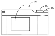
次に、本発明の実施の形態を図面に基づいて説明する。図1は本発明の一実施形態であるデジタルカメラ10の構成の概略を示す構成図、図2はデジタルカメラ10の斜視図、図3はデジタルカメラ10の背面図である。
Next, embodiments of the present invention will be described with reference to the drawings. FIG. 1 is a configuration diagram showing an outline of the configuration of a
本実施形態のデジタルカメラ10は、図1に示すように、被写体の像を光電変換して生成した画像信号に基づいて撮影画像を生成するメイン電子撮像装置20と、このメイン電子撮像装置20とは別に設けられ被写体を光電変換して生成した画像信号に基づいてファインダ画像を生成し該ファインダ画像がディスプレイ47に表示されるよう制御する電子ファインダ装置40と、充放電可能なバッテリ60とを備えている。
As shown in FIG. 1, the
メイン電子撮像装置20は、交換可能な撮影レンズ21と、光を光電変換によって電気信号に変換するイメージセンサ22と、撮影レンズ21とイメージセンサ22との間に配置されたフォーカルプレーンシャッタ23と、イメージセンサ22の種々の動作の開始タイミングをドライバ回路24を介してイメージセンサ22に出力するタイミングジェネレータ(TG)25と、イメージセンサ22から出力された電気信号をデジタル信号に変換するアナログフロントエンド(AFE)26と、ユーザによって操作される各種の操作スイッチ群27と、被写体までの距離を検出可能な測距センサ28と、各種制御を実行するメイン制御装置30とを備えている。
The main
撮影レンズ21は、図示しないレンズマウントを介して着脱自在に取り付けられ、収差を抑えるために凸レンズと凹レンズとを組み合わせて構成されたレンズ群21aと、光量を調節する絞り機構21bとを備えている。この撮影レンズ21は、ユーザによって回転操作がなされることにより焦点距離が変わる距離リング21cと、撮影レンズ21の奥側の端部に設けられ距離リング21cの回転量に応じて繰り出し量が変化する繰り出し部21dとを備えている。なお、絞り機構21bはレンズ群21aの群構成の中に配置されていてもよい。
The
イメージセンサ22は、マトリックス状に配置された複数のフォトダイオード22aと、各フォトダイオード22aごとに形成されフォトダイオード22aから受け取った電荷を垂直方向に転送可能な垂直転送用CCD22bと、垂直方向の終端に位置する垂直転送用CCD22bから受け取った電荷を水平方向に転送可能な水平転送用CCD22cとを備えている。フォトダイオード22aは、画素ごとに設けられた光電変換素子であり、露光されたときの光を電荷に変換して蓄積する。このフォトダイオード22aは、電子シャッタ機能を有しており、この電子シャッタ機能により電荷を図示しない基板へ逃がすことができるようになっている。垂直転送用CCD22b及び水平転送用CCD22cは、電荷転送素子であり、露光中は動作しないが露光する直前のタイミングや露光したあと電荷をフォトダイオード22aから受け取る前のタイミングでCCD22b,22cに貯まったノイズとなる不要な電荷を掃き出し、露光後の電荷をフォトダイオード22aから受け取り順次転送することにより画像信号を読み出すようになっている。これらのフォトダイオード22aや垂直転送用CCD22b,水平転送用CCD22cは、ドライバ回路24によって駆動される。なお、ここではイメージセンサ22としてCCDイメージセンサを例示したが、CMOS型のイメージセンサを採用してもよい。
The
フォーカルプレーンシャッタ23は、シャッタの開閉を先幕と後幕とからなるシャッタ幕を作動させることにより行うものである。このフォーカルプレーンシャッタ23では、イメージセンサ22の1点に注目したときに、その1点を先幕の後端が通過して露光され始めてから後幕の先端が通過して遮光されるまでの時間がシャッタスピードに相当する。
The
TG25は、垂直転送用CCD22bの駆動速度を決定する垂直ラインシフトパルスや水平転送用CCD22cの駆動速度を決定する水平ラインシフトパルスの出力タイミングのほか、各種デバイスの動作の同期をとるための同期信号の出力タイミングなどをドライバ回路24に出力するものである。
The TG 25 is a synchronization signal for synchronizing the operation of various devices in addition to the output timing of the vertical line shift pulse for determining the driving speed of the
AFE26は、イメージセンサ22においてフォトダイオード22aから読み出された画像アナログ信号から光学的な黒信号レベルを再現し、相関二重サンプラ(CDS)処理回路を経てノイズを抑えて信号を読み込み、適正な信号レベルに増幅する可変増幅アンプを経て10〜14ビット程度のデジタル信号に変換して出力する回路である。このAFE26から出力されたデジタル信号は、表示制御装置48内の図示しない画像処理機能ブロックでRGB画素の色補間処理やホワイトバランス処理、色再現処理、ガンマ補正処理などのデジタルカメラでは周知の画像処理が施されたあと圧縮されてJPEGファイルとしてメモリカード38に格納される。
The
操作スイッチ群27は、ユーザの操作によって押下されると撮影レンズ21を通じてイメージセンサ22上に結像した画像を取り込むタイミングをメイン制御装置30へ出力するシャッタボタン27aのほか、シャッタスピードや露出値を設定可能なダイヤルスイッチ27b,ユーザによって巻上操作がなされるとフォーカルプレーンシャッタ23のシャッタ幕をシャッタの切られた状態から再度次回のシャッタ動作が可能な状態に引き上げて機械的に固定する巻上レバー27cなどを含む。
When the
測距センサ28は、本実施形態では、大まかな距離を測定する赤外線センサと正確な距離を測定する位相差センサとから構成されている。赤外線センサは、被写体に向けて赤外線を発射する発光ダイオードと、その被写体からの赤外線の反射光を受光する受光素子とからなり、受光素子への入射角度に応じて被写体までの距離を表す距離信号を出力する。位相差センサは、ある間隔をもって配置された2組のレンズと、各レンズの後方に配置されたエリアセンサとからなり、被写体から入射する像を各エリアセンサ上に結像させ、各像のエリアセンサ内の位置の位相差を元に三角測量の原理で距離を測距するものである。ここでは、近距離(予め定めた閾値未満)のときには赤外線センサを用いて測距し、遠距離(予め定めた閾値以上)のときには位相差センサを用いて測距することとした。
In the present embodiment, the
メイン制御装置30は、CPU32を中心とするマイクロプロセッサとして構成されており、処理プログラムや各種テーブルを記憶するROM34と、データを一時的に記憶するRAM36と、図示しない入出力ポートおよび通信ポートとを備えている。メイン制御装置30には、操作スイッチ群27からの各種のスイッチ信号、AFE26からのデジタル信号、メモリカード38から読み出した各種データなどが入力される。また、メイン制御装置30からは、フォーカルプレーンシャッタ23へのシャッタ駆動信号、TG25への制御信号、メモリカード38への画像要求信号などが出力される。また、メイン制御装置30は、電子ファインダ装置40の表示制御装置48とデータのやり取りが可能である。
The
電子ファインダ装置40は、レンズ41と、光を光電変換によって電気信号に変換するイメージセンサ42と、イメージセンサ42の種々の動作の開始タイミングをドライバ回路44を介してイメージセンサ42に出力するTG45と、イメージセンサ22から出力された電気信号をデジタル信号に変換するAFE46と、ファインダ画像を表示可能なディスプレイ47と、撮影レンズ21の繰り出し部21dの繰り出し量に応じて機械的に変位する距離計連動コロ29の動作を検出して撮影レンズ21の距離情報を出力するコロ位置センサ49と、TG45への制御信号を出力したりコロ位置センサ49からの距離情報を入力したりすると共にこの距離情報に基づいてAFE46から出力されたデジタル信号を画像表示信号に変換したあとファインダ画像としてディスプレイ47に表示する表示制御装置48とを備えている。表示制御装置48は、図示しないが、RGB画素の色補間処理やホワイトバランス処理、色再現処理、ガンマ補正処理などのデジタルカメラでは周知の画像処理を実行する画像処理機能ブロックを備えている。なお、イメージセンサ42やドライバ回路44,TG45は前出のイメージセンサ22やドライバ回路24,TG25と同様の構成のため、ここではその説明を省略する。但し、イメージセンサ22は数百万〜千数百万画素であるのに対してイメージセンサ42は数十万画素〜数百万に過ぎず、イメージセンサ42はイメージセンサ22に比べて光電変換素子の数がはるかに少ないため安価である。
The
バッテリ60は、充放電可能なリチウム水素電池やニッケル水素電池などに代表される二次電池である。このバッテリ60には、図示しない電源ユニットが接続され、この電源ユニットを介して適宜必要な電圧レベルに変換した電圧を各種回路やデバイスに供給する。
The
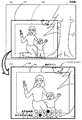
次に、こうして構成された本実施形態のデジタルカメラ10の動作について説明する。図4は、表示制御装置48により実行されるファインダ画像表示ルーチンのフローチャートである。このルーチンは、図示しない電源スイッチがオンにされたあとオフにされるまで実行される。このルーチンが開始されると、表示制御装置48は、まず、電子ファインダ装置40のイメージセンサ42の露光を行い(ステップS100)、その後イメージセンサ42から画像信号を読み出し(ステップS110)、その画像信号をデジタル信号に変換する(ステップS120)。これらの動作はTG45及びドライバ回路44及びAFE46により実行される。続いて、画素補間処理などの周知の画像処理を実行することにより原画像を生成する(ステップS130)。図5は原画像の一例を示す説明図である。続いて、撮影レンズ21の焦点距離に基づいて、イメージセンサ22からの画像信号によって得られる撮影画像の範囲に相当する撮影範囲PAよりも一回り大きなファインダ範囲FAを設定する(ステップS140)。ファインダ範囲FAは、撮影範囲PA(ファインダ範囲FAの面積の30−80%,好ましくは40−65%)を略中央に据えている。このファインダ範囲FAは、原画像からファインダ画像を切り出すための切り出し枠としても利用されるものであり、撮影レンズ21の焦点距離に対応してその大きさが決められている。なお、撮影レンズ21の焦点距離は図示しないレンズ設定スイッチにより28mm,35mm,50mmのいずれかに設定される。続いて、コロ位置センサ49からの距離情報に基づいてファインダ範囲FAのパララックス補正を行う(ステップS150)。コロ位置センサ49から得られる距離情報は、通常は被写体までの距離を表していると考えられる。ここで、メイン電子撮像装置20のイメージセンサ22が被写体をみている位置と電子ファインダ装置40のイメージセンサ42が被写体をみている位置とは数センチ離れていることから(図2参照)、被写体までの距離が短くなるほどイメージセンサ22から得られる画像とイメージセンサ42から得られる画像とのズレ(パララックス)が大きくなる。本実施例では、原画像上のファインダ範囲FAの位置について、このようなパララックスをなくすように補正する。具体的には、被写体までの距離が短くなるほどファインダ範囲FAを撮影レンズ21の方向に動かす。図5(a)はパララックス補正前の状態を示し、図5(b)はパララックス補正後の状態を示す。
Next, the operation of the
こうしてパララックス補正を行ったあと、原画像からファインダ範囲FAを切り出し(ステップS160)、切り出した画像に撮影範囲PAの外縁をなす撮影枠47aを重畳してファインダ画像を生成し(ステップS170)、そのファインダ画像をディスプレイ47に表示し(ステップS180)、再びステップS100に戻る。図6はファインダ画像の一例を示す説明図であり、図6(a)はファインダ範囲FAを切り出す前の原画像を示し、図6(b)はファインダ範囲FAを切り出してディスプレイ47に表示したファインダ画像を示す。
After performing the parallax correction, the finder range FA is cut out from the original image (step S160), and a finder image is generated by superimposing the shooting frame 47a that forms the outer edge of the shooting range PA on the cut out image (step S170). The finder image is displayed on the display 47 (step S180), and the process returns to step S100 again. FIG. 6 is an explanatory diagram showing an example of a finder image. FIG. 6A shows an original image before cutting out the finder range FA, and FIG. 6B shows a finder displayed on the
なお、本実施例のデジタルカメラ10のピント合わせは次のようにして行う。即ち、ディスプレイ47に表示されるファインダ画像の下方には、図6(b)に示すようにAFレベルを表すレベルメータとレンズフォーカス位置を表すレベルメータとが上下に表示されている。各レベルメータは、横一列に複数のマル印を並べて表示されている。また、AFレベルは、測距センサ28により測定された被写体までの距離に対応する位置のマル印が点灯され、レンズフォーカス位置は、距離リング21cがユーザにより回転されるのに連動して点灯するマル印が移動するようになっている。そして、ユーザが距離リング21cを回すことによりAFレベルの点灯したマル印がレンズフォーカス位置の点灯したマル印の真下に来たとき、ピントが合ったと判断することができる。このようなピント合わせの期間中も、上述したファインダ画像表示ルーチンが実行される。
The focusing of the
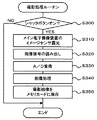
次に、デジタルカメラ10を用いて撮影するときの動作について説明する。図7は、メイン制御装置30のCPU32により実行される撮影処理示ルーチンのフローチャートである。このルーチンは、図示しない電源スイッチがオンにされたあとオフにされるまで所定時間(例えば数msec)ごとに繰り返し実行される。このルーチンが開始されると、CPU32は、まず、シャッタボタン27aが押下されたか否かを判定する(ステップS300)。そして、シャッタボタン27aが押下されていないときにはそのままこのルーチンを終了する。一方、シャッタボタン27aが押下されたときには、イメージセンサ22に貯まったノイズとなる不要な電荷を掃き出すことにより撮影準備を行い、その撮影準備の完了後、フォーカルプレーンシャッタ23によりメイン電子撮像装置20のイメージセンサ22の露光を行い(ステップS310)、その後イメージセンサ42から画像信号を読み出し(ステップS320)、その画像信号をデジタル信号に変換する(ステップS330)。これらの動作はTG45及びドライバ回路44及びAFE46により実行される。なお、露光時間はダイヤルスイッチ27bにより設定されたシャッタスピードによって決定される。続いて、画素補間処理やホワイトバランス処理、ガンマ補正処理などの周知の画像処理を実行することにより撮影画像を生成し(ステップS340)、その撮影画像をメモリカード38に保存し(ステップS350)、本ルーチンを終了する。なお、ここではシャッタスピードをマニュアルで設定する場合について説明したが、被写体の適正な露出量を決定し該決定された露出量に基づいてシャッタスピードを自動的に設定するようにしてもよい。
Next, an operation when photographing using the
ここで、本実施形態の構成要素と本発明の構成要素との対応関係を明らかにする。本実施形態のメイン電子撮像装置20が本発明の撮影画像取得手段に相当し、ディスプレイ47が画像表示手段に相当し、イメージセンサ42が第1の信号生成手段に相当し、表示制御装置48が画像表示制御手段に相当する。また、イメージセンサ22が第2の信号生成手段に相当し、メイン制御装置30が撮影画像生成手段に相当し、測距センサ28が距離検出手段に相当する。なお、本実施形態では、デジタルカメラ10の動作を説明することにより本発明の画像表示方法の一例も明らかにしている。
Here, the correspondence between the components of the present embodiment and the components of the present invention will be clarified. The main
以上詳述した本実施形態のデジタルカメラ10によれば、撮影範囲PAはファインダ範囲FAよりも小さいが一回り小さいサイズとなるようにしているから撮影範囲PAのファインダ範囲FAに占める割合は十分大きくなる。したがって、ユーザは撮影範囲PAの視認を容易かつ確実に行うことができる。また、撮影範囲PAが絶えずファインダ範囲FAの略中央に配置されるため、ユーザが撮影範囲PAを視認する際に違和感を覚えることがない。更に、ファインダ範囲FAは撮影範囲PAを超えているため、撮影範囲PAをわずかに超える部分で興味ある事象があったときにはその事象を素早く捉えることができるというメリットもある。つまり、撮影される範囲を取り巻く非撮影範囲に被写体周辺の状況も必要に応じて見ることも可能であり、撮影に対しての不慮の被写体環境の変化や構図設定の確認に大いに役立つ。
According to the
また、撮影画像に用いる画像信号とファインダ画像に用いる画像信号とがそれぞれ異なるイメージセンサ22,42により生成されるため、両画像信号が共通のイメージセンサにより生成される場合に比べて、撮影の迅速化を図ることができる。例えば、両画像信号が共通のイメージセンサにより生成される場合には、画像信号をファインダ画像に用いたあとそのイメージセンサの電荷の掃き出しなどの処理を行ったうえで撮影画像に用いる画像信号を取得する必要があるためその分時間がかかるのに対し、両画像信号がそれぞれ異なるイメージセンサ22,42により生成される場合にはそのような必要がないため撮影の迅速化を図ることができる。
In addition, since the image signal used for the captured image and the image signal used for the viewfinder image are generated by
更に、ファインダ画像に用いるイメージセンサ42は撮影画像に用いるイメージセンサ22に比べて画素数が少ない(つまり光電変換素子の数が少ない)ため、撮影画像の画質を高くすると共に電子ファインダ機能を比較的安価に搭載することが可能となるし、画像の読み込みを高速で行うことが可能なことから被写体撮影に最も重要なシャッタタイムラグの抑制も可能となる。例えば、VGA画素サイズ(約30万画素)を36MHzの速さで読み出すことが可能であるため1秒間に100枚以上の動画の読み出し(100fps以上)が可能となる。また、画像処理をパイプライン処理で行いながらディスプレイ47に60fpsで表示すると、それを見る撮影者にとって画像の表示遅れは25〜30msec程度となり、それにシャッタ動作後の撮影準備に要する時間を加えると60〜80msecのシャッタタイムラグとなるが、これは通常のフィルムの一眼レフカメラにおいても実用範囲内である。また、画像の読み出しを高速に行い撮影と表示を同期化することで、タイムラグの更なる短縮化が可能となる。
Further, since the
更にまた、撮影画像と撮影枠47a内の画像とが一致するためユーザは撮影範囲を確実に視認することができ、しかもパララックス補正後の撮影枠47aはファインダ画像の略中央に配置されるためユーザが違和感を覚えることはない。 Furthermore, since the photographed image matches the image in the photographing frame 47a, the user can surely see the photographing range, and the photographing frame 47a after the parallax correction is arranged at the approximate center of the finder image. The user does not feel uncomfortable.
なお、本発明は上述した実施形態に何ら限定されることはなく、本発明の技術的範囲に属する限り種々の態様で実施し得ることはいうまでもない。 It should be noted that the present invention is not limited to the above-described embodiment, and it goes without saying that the present invention can be implemented in various modes as long as it belongs to the technical scope of the present invention.
例えば、上述した実施形態では、メイン電子撮像装置20により被写体の像を光電変換して得た画像信号に基づいて撮影画像を生成したが、メイン電子撮像装置20の代わりに被写体の像を銀塩フィルムに写し取ることにより撮影画像を生成する銀塩撮像装置を採用してもよい。この場合も、ユーザは撮影範囲PAの視認を容易かつ確実に行うことができ、しかも、撮影範囲PAが絶えずファインダ範囲FAの略中央に配置されるためユーザが撮影範囲PAを視認する際に違和感を覚えることがないという効果が得られる。また、ファインダ範囲FAは撮影範囲PAを超えているため撮影範囲PAをわずかに超える部分で興味ある事象があったときにはその事象を素早く捉えることができるというメリットも得られる。
For example, in the above-described embodiment, the captured image is generated based on the image signal obtained by photoelectrically converting the subject image by the main
上述した実施形態では、距離リング21cの回転量に基づいて撮影画像と撮影範囲PAとの間に生じるパララックスを補正したが、測距センサ28によって検出された被写体までの距離に基づいて撮影画像と撮影範囲PAとの間に生じるパララックスを補正してもよい。この場合も、撮影画像と撮影枠47a内の画像とが一致するためユーザは撮影範囲を確実に視認することができ、しかもパララックス補正後の撮影枠47aはファインダ画像の略中央に配置されるためユーザが違和感を覚えることはないという効果が得られる。
In the above-described embodiment, the parallax generated between the captured image and the capturing range PA is corrected based on the rotation amount of the
上述した実施形態においてオートホワイトバランスを実行する場合には、電子ファインダ装置40のイメージセンサ42を利用してホワイトバランスを事前に実行してもよい。また、上述した実施形態において、撮影レンズ21がズーム機能を有している場合には、そのズーム動作に連動して電子ファインダ装置40のファインダ画像をデジタルズームするようにしてもよい。
In the embodiment described above, when auto white balance is executed, the white balance may be executed in advance using the
上述した実施形態では、撮影レンズ21の焦点距離は図示しないレンズ設定スイッチにより28mm,35mm,50mmのいずれかに設定されるとしたが、レンズ設定スイッチによる焦点距離の選択肢を4つ以上としてもよいし、焦点距離をユーザが数値入力するようにしてもよい。使用するズームレンズから設定されているズーム率情報を電気的な通信手段でカメラ側に取り込んで、撮影ズームレンズのズーム設定に応じてファインダの光学ズーム又はデジタルズームを行ってもよい。
In the above-described embodiment, the focal length of the photographing
10 デジタルカメラ、20 メイン電子撮像装置、21 撮影レンズ、21a レンズ群、21b 機構、21c 距離リング、21d 繰り出し部、22 イメージセンサ、22a フォトダイオード、22b 垂直転送用CCD、22c 水平転送用CCD、23 フォーカルプレーンシャッタ、24 ドライバ回路、25 タイミングジェネレータ(TG)、26 アナログフロントエンド(AFE)、27 操作スイッチ群、27a シャッタボタン、27b ダイヤルスイッチ、27c 巻上レバー、28 測距センサ、29 距離計連動コロ、30 メイン制御装置、32 CPU、34 ROM、36 RAM、38 メモリカード、40 電子ファインダ装置、41 レンズ、42 イメージセンサ、44 ドライバ回路、45 タイミングジェネレータ(TG)、46 アナログフロントエンド(AFE)、47 ディスプレイ、47a 撮影枠、48 表示制御装置、49 コロ位置センサ、60 バッテリ、FA ファインダ範囲、PA 撮影範囲。 10 digital camera, 20 main electronic imaging device, 21 photographing lens, 21a lens group, 21b mechanism, 21c distance ring, 21d feeding portion, 22 image sensor, 22a photodiode, 22b vertical transfer CCD, 22c horizontal transfer CCD, 23 Focal plane shutter, 24 Driver circuit, 25 Timing generator (TG), 26 Analog front end (AFE), 27 Operation switch group, 27a Shutter button, 27b Dial switch, 27c Hoist lever, 28 Distance sensor, 29 Distance meter interlocking Roller, 30 Main control device, 32 CPU, 34 ROM, 36 RAM, 38 Memory card, 40 Electronic viewfinder device, 41 Lens, 42 Image sensor, 44 Driver circuit, 45 Timing table Nereta (TG), 46 analog front-end (AFE), 47 display, 47a photographing frame, 48 display controller, 49 roller position sensor, 60 battery, FA finder range, PA shooting range.
Claims (7)
表示用画像を表示可能な画像表示手段と、
前記被写体の像を光電変換して画像信号を生成する第1の信号生成手段と、
前記撮影画像に相当する撮影範囲を略中央に据え該撮影範囲よりも一回り大きな画像を前記第1の信号生成手段によって生成された画像信号に基づいて生成し、該生成された画像に前記撮影範囲の外縁を表す撮影枠を付した画像を前記表示用画像とし該表示用画像が前記画像表示手段に表示されるよう制御する画像表示制御手段と、
を備え、
前記画像表示制御手段は、前記表示用画像を生成する際に、ユーザが撮影レンズに取り付けられた距離リングを回転させたときの回転量に基づいて前記撮影画像と前記撮影枠との間に生じるパララックスを補正して前記表示用画像を生成する、
カメラ。 Photographic image acquisition means for capturing an image of a subject obtained through the optical system as a photographic image;
An image display unit capable of displaying a display image,
First signal generation means for photoelectrically converting the image of the subject to generate an image signal;
The generated based a slightly larger images than the shooting range laid substantially in the center of the imaging range corresponding to the photographed image on the image signal generated by said first signal generating means, images that are the product wherein the image denoted by the photographing frame indicating the outer edge of the shooting range and the display image the image display control means for controlling so that the display image is displayed on the image display means,
Equipped with a,
The image display control means is generated between the photographed image and the photographing frame based on a rotation amount when a user rotates a distance ring attached to the photographing lens when generating the display image. Correcting the parallax to generate the display image;
Camera.
表示用画像を表示可能な画像表示手段と、
前記被写体の像を光電変換して画像信号を生成する第1の信号生成手段と、
前記撮影画像に相当する撮影範囲を略中央に据え該撮影範囲よりも一回り大きな画像を前記第1の信号生成手段によって生成された画像信号に基づいて生成し、該生成された画像に前記撮影範囲の外縁を表す撮影枠を付した画像を前記表示用画像とし該表示用画像が前記画像表示手段に表示されるよう制御する画像表示制御手段と、
前記被写体までの距離を検出する距離検出手段と、
を備え、
前記画像表示制御手段は、前記表示用画像を生成する際に、前記距離検出手段によって検出された前記被写体までの距離に基づいて前記撮影画像と前記撮影枠との間に生じるパララックスを補正して前記表示用画像を生成する、
カメラ。 Photographic image acquisition means for capturing an image of a subject obtained through the optical system as a photographic image;
An image display unit capable of displaying a display image,
First signal generation means for photoelectrically converting the image of the subject to generate an image signal;
The generated based a slightly larger images than the shooting range laid substantially in the center of the imaging range corresponding to the photographed image on the image signal generated by said first signal generating means, images that are the product wherein the image denoted by the photographing frame indicating the outer edge of the shooting range and the display image the image display control means for controlling so that the display image is displayed on the image display means,
Distance detecting means for detecting a distance to the subject;
Equipped with a,
The image display control unit corrects a parallax generated between the captured image and the imaging frame based on a distance to the subject detected by the distance detection unit when generating the display image. To generate the display image,
Camera.
前記被写体の像をイメージセンサを用いて第2の画像として取得して保存する第2の画像取得手段と、 Second image acquisition means for acquiring and storing the image of the subject as a second image using an image sensor;
前記第1の画像と前記第2の画像との間に生じるパララックスの程度を取得するパララックス取得手段と、 Parallax acquisition means for acquiring the degree of parallax generated between the first image and the second image;
前記第2の画像の前記パララックスの程度に基づいた位置に前記第1の画像の範囲に相当する撮影枠が付され、該撮影枠が略中央に据えられた表示用画像を表示する画像表示手段と、 An image display for displaying a display image in which a shooting frame corresponding to the range of the first image is attached at a position based on the degree of parallax of the second image, and the shooting frame is set substantially at the center. Means,
を備えたカメラ。 With a camera.
(a)光学系を介して得られる被写体の像を撮影画像として取り込むステップと、
(b)前記被写体の像を光電変換して画像信号を生成するステップと、
(c)前記撮影画像に相当する撮影範囲を略中央に据え該撮影範囲よりも一回り大きな画像を前記ステップ(b)で生成された画像信号に基づいて生成し、該生成された画像に前記撮影範囲の外縁を表す撮影枠を付した画像を前記表示用画像とし該表示用画像が前記画像表示手段に表示されるよう制御するステップと、
を含み、
前記ステップ(c)では、前記表示用画像を生成する際に、ユーザが撮影レンズに取り付けられた距離リングを回転させたときの回転量に基づいて前記撮影画像と前記撮影枠との間に生じるパララックスを補正して前記表示用画像を生成する、
画像表示方法。 An image display method for displaying a display image on an image display means,
(A) capturing a subject image obtained through the optical system as a captured image;
(B) photoelectrically converting the image of the subject to generate an image signal;
(C) said slightly larger images than the shooting range laid substantially in the center of the imaging range corresponding to the captured image generated based on the image signal generated in step (b), which is the generated image Controlling an image obtained by adding an imaging frame indicating an outer edge of the imaging range to the image as the display image, and displaying the display image on the image display means;
Only including,
In the step (c), when the display image is generated, it is generated between the captured image and the imaging frame based on the rotation amount when the user rotates the distance ring attached to the imaging lens. Correcting the parallax to generate the display image;
Image display method.
(a)光学系を介して得られる被写体の像を撮影画像として取り込むステップと、
(b)前記被写体の像を光電変換して画像信号を生成するステップと、
(c)前記被写体までの距離を検出するステップと、
(d)前記撮影画像に相当する撮影範囲を略中央に据え該撮影範囲よりも一回り大きな画像を前記ステップ(b)で生成された画像信号に基づいて生成し、該生成された画像に前記撮影範囲の外縁を表す撮影枠を付した画像を前記表示用画像とし該表示用画像が前記画像表示手段に表示されるよう制御するステップと、
を含み、
前記ステップ(d)では、前記表示用画像を生成する際に、前記ステップ(c)で検出された前記被写体までの距離に基づいて前記撮影画像と前記撮影枠との間に生じるパララックスを補正して前記表示用画像を生成する、
画像表示方法。 An image display method for displaying a display image on an image display means,
(A) capturing a subject image obtained through the optical system as a captured image;
(B) photoelectrically converting the image of the subject to generate an image signal;
(C) detecting a distance to the subject;
; (D) a slightly larger images than the shooting range laid substantially in the center of the imaging range corresponding to the captured image generated based on the image signal generated in step (b), which is the generated image Controlling an image obtained by adding an imaging frame indicating an outer edge of the imaging range to the image as the display image, and displaying the display image on the image display means;
Only including,
In the step (d), when generating the display image, the parallax generated between the captured image and the imaging frame is corrected based on the distance to the subject detected in the step (c). And generating the display image,
Image display method.
(a)被写体の像を第1の画像として取得して保存するステップと、(A) acquiring and storing an image of a subject as a first image;
(b)前記被写体の像をイメージセンサを用いて第2の画像として取得して保存するステップと、(B) acquiring and storing the image of the subject as a second image using an image sensor;
(c)前記第1の画像と前記第2の画像との間に生じるパララックスの程度を取得するステップと、(C) obtaining a degree of parallax generated between the first image and the second image;
(d)前記第2の画像の前記パララックスの程度に基づいた位置に前記第1の画像の範囲に相当する撮影枠が付され、該撮影枠が略中央に据えられた画像を前記表示用画像として前記画像表示手段に表示するステップと、(D) A shooting frame corresponding to the range of the first image is attached at a position based on the degree of parallax of the second image, and an image in which the shooting frame is set at a substantially center is used for the display Displaying on the image display means as an image;
を含む画像表示方法。 An image display method including:
Priority Applications (2)
| Application Number | Priority Date | Filing Date | Title |
|---|---|---|---|
| JP2006091523A JP4333685B2 (en) | 2006-03-29 | 2006-03-29 | Camera, image display method and program thereof |
| US11/731,591 US7693415B2 (en) | 2006-03-29 | 2007-03-29 | Camera with electronic finder, image display method, and corresponding program |
Applications Claiming Priority (1)
| Application Number | Priority Date | Filing Date | Title |
|---|---|---|---|
| JP2006091523A JP4333685B2 (en) | 2006-03-29 | 2006-03-29 | Camera, image display method and program thereof |
Publications (2)
| Publication Number | Publication Date |
|---|---|
| JP2007267205A JP2007267205A (en) | 2007-10-11 |
| JP4333685B2 true JP4333685B2 (en) | 2009-09-16 |
Family
ID=38559076
Family Applications (1)
| Application Number | Title | Priority Date | Filing Date |
|---|---|---|---|
| JP2006091523A Active JP4333685B2 (en) | 2006-03-29 | 2006-03-29 | Camera, image display method and program thereof |
Country Status (2)
| Country | Link |
|---|---|
| US (1) | US7693415B2 (en) |
| JP (1) | JP4333685B2 (en) |
Families Citing this family (12)
| Publication number | Priority date | Publication date | Assignee | Title |
|---|---|---|---|---|
| GB2457867B (en) * | 2007-10-08 | 2010-11-03 | Keymed | Electronic camera |
| US8428120B2 (en) * | 2007-12-11 | 2013-04-23 | Taiwan Imagingtek Corporation | Method and apparatus of Bayer pattern direct video compression |
| JP5432664B2 (en) * | 2009-10-22 | 2014-03-05 | キヤノン株式会社 | Imaging device |
| US9041853B2 (en) * | 2010-12-01 | 2015-05-26 | Nec Casio Mobile Communications, Ltd. | Mobile terminal, method of image processing, and program |
| FR2969819A1 (en) * | 2010-12-22 | 2012-06-29 | St Microelectronics Grenoble 2 | THREE DIMENSIONAL IMAGE SENSOR |
| US8821306B2 (en) | 2011-05-27 | 2014-09-02 | Acushnet Company | Fitting system for a golf club |
| US20130165249A1 (en) | 2011-12-22 | 2013-06-27 | Ryan Margoles | Golf club with improved weight distribution |
| US9421421B2 (en) | 2014-03-14 | 2016-08-23 | Acushnet Company | Golf club with improved weight distribution |
| US9211456B2 (en) | 2014-03-14 | 2015-12-15 | Acushnet Company | Golf club with improved weight distribution |
| US9937397B2 (en) | 2014-03-14 | 2018-04-10 | Acushnet Company | Golf club with improved weight distribution |
| US9616298B1 (en) | 2015-09-24 | 2017-04-11 | Acushnet Company | Golf club with improved weighting |
| CN113812139A (en) * | 2019-05-21 | 2021-12-17 | 索尼集团公司 | Image processing apparatus, image processing method, and program |
Family Cites Families (7)
| Publication number | Priority date | Publication date | Assignee | Title |
|---|---|---|---|---|
| JPH0214675A (en) | 1988-07-01 | 1990-01-18 | Fuji Photo Film Co Ltd | Electronic image pickup device |
| SE461619B (en) * | 1988-07-06 | 1990-03-05 | Hasselblad Ab Victor | DEVICE FOR CAMERAS CONCERNING A COMPOSITION OF A PHOTOCHEMICAL AND ELECTRONIC CAMERA |
| JP2001053992A (en) | 1999-08-05 | 2001-02-23 | Olympus Optical Co Ltd | Camera to be used for silver photographing and also for electronic image pickup |
| JP2001296599A (en) * | 2000-04-12 | 2001-10-26 | Olympus Optical Co Ltd | Camera used for silver halide photography and also for electronic image pickup |
| US6859619B2 (en) * | 2002-06-21 | 2005-02-22 | Pentax Corporation | Autofocus camera having multipoint focus detecting system |
| CN100527854C (en) * | 2003-06-23 | 2009-08-12 | 索尼株式会社 | Image processing method and device |
| WO2006060746A2 (en) * | 2004-12-03 | 2006-06-08 | Infrared Solutions, Inc. | Visible light and ir combined image camera with a laser pointer |
-
2006
- 2006-03-29 JP JP2006091523A patent/JP4333685B2/en active Active
-
2007
- 2007-03-29 US US11/731,591 patent/US7693415B2/en active Active
Also Published As
| Publication number | Publication date |
|---|---|
| JP2007267205A (en) | 2007-10-11 |
| US7693415B2 (en) | 2010-04-06 |
| US20070230945A1 (en) | 2007-10-04 |
Similar Documents
| Publication | Publication Date | Title |
|---|---|---|
| JP4333685B2 (en) | Camera, image display method and program thereof | |
| JP4939901B2 (en) | Distance image generation method and apparatus | |
| JP4452951B2 (en) | Distance image generation method and apparatus | |
| JP5322783B2 (en) | IMAGING DEVICE AND CONTROL METHOD OF IMAGING DEVICE | |
| JP5022758B2 (en) | Imaging apparatus, imaging system, and driving method of imaging apparatus | |
| TW201004329A (en) | Image capture apparatus and program | |
| JP2009244858A (en) | Image capturing apparatus and image processing method | |
| WO2013146019A1 (en) | Imaging device | |
| JP2011022501A (en) | Compound-eye imaging apparatus | |
| JP2019092119A (en) | Imaging device, lens device, and control method thereof | |
| JP6685845B2 (en) | Imaging device and imaging program | |
| JP2015198431A (en) | Image processing apparatus, imaging device, determination method, driving method and program | |
| JP2010226362A (en) | Imaging apparatus and control method thereof | |
| JP2007221268A (en) | Imaging apparatus | |
| JP4865648B2 (en) | Imaging device | |
| JP4665833B2 (en) | Imaging apparatus, control method thereof, and program thereof | |
| JP2009086030A (en) | Imaging apparatus, method and program | |
| JP2009053568A (en) | Imaging apparatus and imaging system | |
| JP2010114577A (en) | Imaging apparatus, image processor, control method and image processing method of imaging apparatus | |
| JP2007248698A (en) | Method and apparatus for imaging | |
| JP5896947B2 (en) | IMAGING DEVICE AND ITS CONTROL METHOD, IMAGING SYSTEM, PROGRAM, AND STORAGE MEDIUM | |
| JP5351298B2 (en) | Compound eye imaging device | |
| JP2007228073A (en) | Lens unit and digital camera | |
| JP2020085968A (en) | Imaging apparatus and control method for the same, program, storage medium | |
| US9618723B2 (en) | Image capturing apparatus, control method thereof, lens unit, and image capturing system |
Legal Events
| Date | Code | Title | Description |
|---|---|---|---|
| A977 | Report on retrieval |
Free format text: JAPANESE INTERMEDIATE CODE: A971007 Effective date: 20090323 |
|
| A131 | Notification of reasons for refusal |
Free format text: JAPANESE INTERMEDIATE CODE: A131 Effective date: 20090331 |
|
| A521 | Request for written amendment filed |
Free format text: JAPANESE INTERMEDIATE CODE: A523 Effective date: 20090513 |
|
| TRDD | Decision of grant or rejection written | ||
| A01 | Written decision to grant a patent or to grant a registration (utility model) |
Free format text: JAPANESE INTERMEDIATE CODE: A01 Effective date: 20090602 |
|
| A01 | Written decision to grant a patent or to grant a registration (utility model) |
Free format text: JAPANESE INTERMEDIATE CODE: A01 |
|
| A61 | First payment of annual fees (during grant procedure) |
Free format text: JAPANESE INTERMEDIATE CODE: A61 Effective date: 20090615 |
|
| FPAY | Renewal fee payment (event date is renewal date of database) |
Free format text: PAYMENT UNTIL: 20120703 Year of fee payment: 3 |
|
| R150 | Certificate of patent or registration of utility model |
Ref document number: 4333685 Country of ref document: JP Free format text: JAPANESE INTERMEDIATE CODE: R150 Free format text: JAPANESE INTERMEDIATE CODE: R150 |
|
| FPAY | Renewal fee payment (event date is renewal date of database) |
Free format text: PAYMENT UNTIL: 20120703 Year of fee payment: 3 |
|
| FPAY | Renewal fee payment (event date is renewal date of database) |
Free format text: PAYMENT UNTIL: 20130703 Year of fee payment: 4 |
|
| S531 | Written request for registration of change of domicile |
Free format text: JAPANESE INTERMEDIATE CODE: R313531 |
|
| R350 | Written notification of registration of transfer |
Free format text: JAPANESE INTERMEDIATE CODE: R350 |
|
| R250 | Receipt of annual fees |
Free format text: JAPANESE INTERMEDIATE CODE: R250 |
|
| R250 | Receipt of annual fees |
Free format text: JAPANESE INTERMEDIATE CODE: R250 |
|
| R250 | Receipt of annual fees |
Free format text: JAPANESE INTERMEDIATE CODE: R250 |
|
| R250 | Receipt of annual fees |
Free format text: JAPANESE INTERMEDIATE CODE: R250 |
|
| R250 | Receipt of annual fees |
Free format text: JAPANESE INTERMEDIATE CODE: R250 |