EP2556256B1 - Drehkolbenpumpe und verfahren zum betreiben einer drehkolbenpumpe - Google Patents
Drehkolbenpumpe und verfahren zum betreiben einer drehkolbenpumpe Download PDFInfo
- Publication number
- EP2556256B1 EP2556256B1 EP11729047.8A EP11729047A EP2556256B1 EP 2556256 B1 EP2556256 B1 EP 2556256B1 EP 11729047 A EP11729047 A EP 11729047A EP 2556256 B1 EP2556256 B1 EP 2556256B1
- Authority
- EP
- European Patent Office
- Prior art keywords
- rotary
- drive
- driven
- pump
- elastic element
- Prior art date
- Legal status (The legal status is an assumption and is not a legal conclusion. Google has not performed a legal analysis and makes no representation as to the accuracy of the status listed.)
- Active
Links
Images



Classifications
-
- F—MECHANICAL ENGINEERING; LIGHTING; HEATING; WEAPONS; BLASTING
- F04—POSITIVE - DISPLACEMENT MACHINES FOR LIQUIDS; PUMPS FOR LIQUIDS OR ELASTIC FLUIDS
- F04C—ROTARY-PISTON, OR OSCILLATING-PISTON, POSITIVE-DISPLACEMENT MACHINES FOR LIQUIDS; ROTARY-PISTON, OR OSCILLATING-PISTON, POSITIVE-DISPLACEMENT PUMPS
- F04C15/00—Component parts, details or accessories of machines, pumps or pumping installations, not provided for in groups F04C2/00 - F04C14/00
- F04C15/0057—Driving elements, brakes, couplings, transmission specially adapted for machines or pumps
- F04C15/0061—Means for transmitting movement from the prime mover to driven parts of the pump, e.g. clutches, couplings, transmissions
-
- F—MECHANICAL ENGINEERING; LIGHTING; HEATING; WEAPONS; BLASTING
- F01—MACHINES OR ENGINES IN GENERAL; ENGINE PLANTS IN GENERAL; STEAM ENGINES
- F01C—ROTARY-PISTON OR OSCILLATING-PISTON MACHINES OR ENGINES
- F01C17/00—Arrangements for drive of co-operating members, e.g. for rotary piston and casing
-
- F—MECHANICAL ENGINEERING; LIGHTING; HEATING; WEAPONS; BLASTING
- F01—MACHINES OR ENGINES IN GENERAL; ENGINE PLANTS IN GENERAL; STEAM ENGINES
- F01C—ROTARY-PISTON OR OSCILLATING-PISTON MACHINES OR ENGINES
- F01C17/00—Arrangements for drive of co-operating members, e.g. for rotary piston and casing
- F01C17/02—Arrangements for drive of co-operating members, e.g. for rotary piston and casing of toothed-gearing type
-
- F—MECHANICAL ENGINEERING; LIGHTING; HEATING; WEAPONS; BLASTING
- F01—MACHINES OR ENGINES IN GENERAL; ENGINE PLANTS IN GENERAL; STEAM ENGINES
- F01C—ROTARY-PISTON OR OSCILLATING-PISTON MACHINES OR ENGINES
- F01C21/00—Component parts, details or accessories not provided for in groups F01C1/00 - F01C20/00
- F01C21/008—Driving elements, brakes, couplings, transmissions specially adapted for rotary or oscillating-piston machines or engines
-
- F—MECHANICAL ENGINEERING; LIGHTING; HEATING; WEAPONS; BLASTING
- F04—POSITIVE - DISPLACEMENT MACHINES FOR LIQUIDS; PUMPS FOR LIQUIDS OR ELASTIC FLUIDS
- F04C—ROTARY-PISTON, OR OSCILLATING-PISTON, POSITIVE-DISPLACEMENT MACHINES FOR LIQUIDS; ROTARY-PISTON, OR OSCILLATING-PISTON, POSITIVE-DISPLACEMENT PUMPS
- F04C2/00—Rotary-piston machines or pumps
- F04C2/08—Rotary-piston machines or pumps of intermeshing-engagement type, i.e. with engagement of co-operating members similar to that of toothed gearing
- F04C2/12—Rotary-piston machines or pumps of intermeshing-engagement type, i.e. with engagement of co-operating members similar to that of toothed gearing of other than internal-axis type
- F04C2/126—Rotary-piston machines or pumps of intermeshing-engagement type, i.e. with engagement of co-operating members similar to that of toothed gearing of other than internal-axis type with radially from the rotor body extending elements, not necessarily co-operating with corresponding recesses in the other rotor, e.g. lobes, Roots type
-
- F—MECHANICAL ENGINEERING; LIGHTING; HEATING; WEAPONS; BLASTING
- F04—POSITIVE - DISPLACEMENT MACHINES FOR LIQUIDS; PUMPS FOR LIQUIDS OR ELASTIC FLUIDS
- F04C—ROTARY-PISTON, OR OSCILLATING-PISTON, POSITIVE-DISPLACEMENT MACHINES FOR LIQUIDS; ROTARY-PISTON, OR OSCILLATING-PISTON, POSITIVE-DISPLACEMENT PUMPS
- F04C2230/00—Manufacture
- F04C2230/90—Improving properties of machine parts
- F04C2230/91—Coating
-
- F—MECHANICAL ENGINEERING; LIGHTING; HEATING; WEAPONS; BLASTING
- F04—POSITIVE - DISPLACEMENT MACHINES FOR LIQUIDS; PUMPS FOR LIQUIDS OR ELASTIC FLUIDS
- F04C—ROTARY-PISTON, OR OSCILLATING-PISTON, POSITIVE-DISPLACEMENT MACHINES FOR LIQUIDS; ROTARY-PISTON, OR OSCILLATING-PISTON, POSITIVE-DISPLACEMENT PUMPS
- F04C2240/00—Components
- F04C2240/40—Electric motor
- F04C2240/402—Plurality of electronically synchronised motors
Definitions
- the present invention relates to a method for operating a rotary lobe pump.
- the rotary lobe pump to be operated with the method according to the invention is equipped with at least one motor which drives at least two rotary lobes rotating in relation to one another.
- the rotary pistons move in a pump housing.
- the at least two rotary pistons are arranged on a first output shaft and a second output shaft.
- the two output shafts are synchronized and driven in such a way that the at least two rotary pistons are in operative connection with one another and form an active pair.
- German patent application DE 38 25 372 A1 describes an engine with two ring cylinders arranged in one plane, in which rotary pistons are arranged.
- the revolving pistons are attached to the periphery of a rotor disk that is rotationally fixed on a shaft.
- the rotor disks have a corresponding slot in the periphery in which the respective ring cylinders pass, the two rotating pistons meshing with one another.
- the task of the engine is to set the rotating pistons in rotation by means of combustion, a suitable substance, and to drive the shafts via them.
- the rotating pistons can rotate in the same direction as well as in opposite directions.
- German patent DE 10 2005 062 892 B2 discloses a rotary piston machine used as an internal combustion engine or as a work machine.
- the two diametrically arranged rotary pistons create periodically variable working chambers in a ring cylinder housing.
- the rotary pistons are connected in a torsionally rigid manner by means of shafts that are pushed one inside the other so that the shafts act individually on a common output shaft via an envelope drive system with elliptical transmission disks.
- the enveloping drive can be constructed with a toothed belt, toothed chain or chain.
- the GB 2 207 190 A describes an oil-free vacuum pump, the rotors being toothed.
- An elastic belt is used as the driving belt, which consists of a woven or metal reinforced rubber or polymer. This is selected in such a way that maximum engagement and power transmission without slippage with minimal expansion, whether under tensile stress or after extended use, can be guaranteed.
- the EP 1 927 758 A1 describes driving the rotors by means of a gear with gearwheels, a belt additionally being guided over deflection rollers in order to support the synchronization. There is a double synchronization, on the one hand via the gears and on the other hand via the belt. The torque is transmitted between the rotors in two ways, via the deflection rollers and via the synchronous gear.
- the GB 2 176 848 A describes a compressor in which the rotational force is magnetically applied directly to the working rotor by means of a static seal and not by the gearwheels, which are mainly used to transmit dynamic loads.
- the DE 197 11 510 A1 describes a screw compressor which comprises a first and a second screw compressor unit.
- the screw compressor comprises a drive unit and the belt drive coupling the drive unit with the screw compressor units.
- the belt drive comprises a first and a second pulley designed for torque transmission and a drive pulley connected to the drive shaft of the drive unit for torque transmission.
- a transmission belt is provided which is in a transmission plane over the first and the second pulley and runs over the drive pulley, the power transmitted by the belt transmission being greater than 10 kW.
- the DE 103 34 481 A1 describes a spindle vacuum pump with a pre-tensioned belt drive.
- a closed belt drive from a motor pulley simultaneously drives the two equally sized rotor-fixed belt wheels via a change of curvature in the belt drive.
- the JP 6 185 483 A1 describes a device for connecting the ends of webs lying on one another or with multiple surfaces, in particular windable metal strips.
- the WO 2009/076689 A2 describes a drive with at least two intermeshing toothing elements.
- At least one toothed element comprises a base body, which has teeth along a circumference, which at least partially have an abradable polymer coating on a surface.
- the invention has for its object to provide a method with which a rotary lobe pump can be operated trouble-free and economically.
- the rotary lobe pump to be operated is provided with at least one motor and with at least two rotary lobes rotating in relation to one another.
- the at least two rotary pistons are arranged in a pump housing. Furthermore, the at least two rotary pistons are arranged on a first output shaft and a second output shaft.
- the first output shaft and the second output shaft are synchronized and driven with one another in such a way that the at least two rotary pistons mesh with one another. This is achieved in that the output shafts can be driven and synchronized via an elastic element. Under the intermeshing is to be understood that the rotary lobes form an interrelated pair of interactions.
- the design of the rotary lobe pump with an elastic element has considerable advantages over the prior art. Firstly, the rotary lobes are secured against clogging by jamming solid bodies in the rotary lobe pump, and secondly, the rotary lobe pump can be operated oil-free. This high permeability to solids results from the fact that the elastic element can give way in the event of blockages in the area of the rotary lobes. By using the elastic element, there is no need for a conventional gear, which has to run in oil. Furthermore, by simultaneously driving and synchronizing the rotary lobes, the power density of the rotary lobe pump is increased and, at the same time, the weight is reduced.
- the elastic element is an endless, flexible element.
- This endless, flexible element can be a double toothed belt, a chain or a link belt.
- Lubrication must be used when using chains or link belts. The effort for the lubrication of the chains or link belts is significantly less than is the case with conventional rotary lobe pumps driven by gears.
- the double toothed belt can have different profiles. It is important that the double toothed belt has a certain flexibility. This flexibility makes it possible to briefly compensate for the currently occurring synchronous rotation of the rotary lobes by stretching the double toothed belt in the event of a blockage.
- the teeth of the double toothed belt are always designed in such a way that they form optimal active pairs with the teeth of the gear wheels in the system and thus optimally transmit the forces from the drive shaft to the rotary pistons.
- the teeth of the double toothed belt should be designed such that they represent the weakest link in the active system when the rotary lobes are completely blocked. This would, for example, rub the teeth at the point of maximum stress.
- the endless, flexible element has a free span length between a first driven wheel and a second driven wheel.
- This free span length represents a buffer area.
- the free span length ensures that the rotary lobe pump is free from solids.
- the larger the free span length the more the rotary lobes can turn against each other.
- This twisting of the Rotary lobes to each other are closed after a maximum of one complete turn of the rotary lobes.
- the fact that the rotation is canceled after a maximum of one complete revolution ensures that the rotary lobe pump functions correctly.
- This means that the length of the free run is directly dependent on the size of the solid particles in the medium to be pumped.
- the larger the solids in the medium the greater the free span length. Of course, this is only possible up to a certain solid size.
- the solids ability of the rotary lobe pump continues to depend on the rotary lobe and its surface condition.
- the length of the free run can be adjusted by the radii of the first driven wheel and the second driven wheel.
- the larger the radii the smaller the free span length.
- the radii of the two driven wheels must always be the same size, otherwise there is no synchronism of the rotary pistons.
- the distance between the output shafts depends on the design of the rotary pistons.
- the larger the rotary lobes the greater the distance between the output shafts. If the distance between the output shafts is large, the active system can also have a large free strand length and thus a high solids flow.
- the free span length also influences the synchronization accuracy. The shorter the length of the free run, the more precisely the rotary lobe pump can be synchronized. This also applies to the possible longitudinal expansion of the free run.
- the elasticity is ensured by plastic-coated gears.
- the plastic coating is designed in such a way that it allows the rotary pistons to be offset from one another.
- the motor is mounted over the actual pump housing.
- This combination of motor and pump is commonly referred to as "piggy back".
- This embodiment has the advantage that the center of gravity of the engine and the rotary lobe pump lie in one axis. Furthermore, the "Piggy Back" enables the rotary lobe pump to be integrated directly and with a short design into a piping system.
- the elastic element enables the rotary lobe pump to be driven by several motors. It is therefore possible, for example, to choose two smaller motors to better distribute the weight of the entire active system. For example, motors that run exactly synchronously are used to drive the rotary lobe pump.
- a device for maintaining the element tension is assigned to the endless, flexible element.
- At least one secondary machine can be driven with the device for maintaining the element tension.
- a secondary machine can be, for example, another pump or a pre-shredder.
- a secondary pump can be used, for example, to add lubricant or to add condensers to the medium to be pumped.
- Devices for tensioning toothed belts and / or chains are known from the prior art. It is also known that there are a large number of secondary devices which can be assigned to a rotary lobe pump. The information given in advance does not represent a final restriction of the protection area.
- the first output shaft and the second output shaft are driven and synchronized by at least one motor via an elastic element.
- An endless, flexible element or at least one elastically coated gear can be used for the elastic element.
- the rotary lobe pump is driven by at least two motors.
- the endless, flexible element is held in tension by a device.
- at least one secondary machine can be driven with this device.
- Figure 6 shows schematically the course of the endless, flexible element with free strand length between the driven wheels.
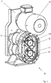
- FIG 1 shows schematically the structure of a rotary lobe pump 20 to be operated with the method according to the invention with a drive and synchronization device.
- a motor 22 is arranged above a pump housing 26.
- the motor 22 is connected to a drive shaft 23 which moves a drive wheel 24.
- An elastic element 44 is driven in rotation via the drive wheel 24.
- a first driven wheel 42 and a second driven wheel 43 are driven via the elastic element 44.
- the first driven wheel 42 is connected to a first driven shaft 40 and the second driven wheel 43 is positively and / or non-positively connected to a second driven shaft 41. Via the first output shaft 40 and the second output shaft 41, the rotary pistons (see Figure 2 ) driven.
- a rotary lobe pump 20 with an open pump housing 26 is shown schematically.
- the motor 22 is mounted above the pump housing 26.
- Of the drive and synchronization device 25 is in the Figure 2 only one mounting plate 21 can be seen.
- the rotary pistons 32 are located in the pump housing 26.
- a rotary piston 32 is driven by the first output shaft 40 and the second rotary piston 32 by the second output shaft 41.
- FIG 3 shows the schematic structure of a drive and synchronization device 25 with a separate tensioning device 34.
- the drive wheel 24 Via the drive shaft 23, the drive wheel 24 is driven, which transmits the rotational forces of the drive shaft 23 to the elastic element 44.
- the elastic element 44 a double toothed belt, drives the first driven wheel 42 and the second driven wheel 43, the first driven wheel 42 rotating the first driven shaft 40 and the second driven wheel 43 the second driven shaft 41. So that the elastic element 44 always has the correct tension, it is held in tension by the tensioning device 34.
- the strength of the preload can be adjusted via a tensioning element 36.
- the first output shaft 40 and the second output shaft 41 have to rotate in opposite directions, the first output gear 42 is driven from the outside of the elastic element 44 and the second output gear 43 from the inside of the elastic element 44. This change of engagement takes place in the area 48 between the drive wheels 42 and 43.
- a drive and synchronization device 25 is shown schematically without a separate tensioning device.
- the elastic element 44 is guided directly from the drive wheel 24 to the first driven wheel 42. From there it is transferred to the second driven wheel 43 via the area 48.
- the motor 22 with the drive shaft 23 and the drive wheel 24 is moved in this exemplary embodiment. With the tensioning element 36, the motor 22 is moved away from the drive wheels 42 and 43 until the necessary pre-tensioning of the elastic element 44 is present.
- FIGS. 5a to 5c show various examples of the arrangement of the motor 22 to the rotary lobe pump 20.
- a motor 22 which is offset laterally to the drive and synchronization device 25 is shown schematically.
- a tensioning roller 38 which holds the elastic element 44 under pre-tension. Because the motor 22 is laterally offset, the length of the elastic element 44 increases, which means that the use of a tensioning device 34 is essential.
- FIG. 5b A drive and synchronization device 25 for a rotary lobe pump is shown, in which the motor 22 is not arranged in close proximity to the drive and synchronization device 25.
- This example is intended to show that it is possible, using an elastic element 44, to install the motor 22 further away from the rotary lobe pump.
- a tensioning device 34 is necessary in order to keep the elastic element 44 in tension.
- Figure 5c shows schematically how a rotary lobe pump (not shown here) can be designed, which is driven by two motors 22.
- two motors 22 are arranged above the drive and synchronization device 25.
- Each of the two motors 22 has a separate drive shaft 23 and a drive wheel 24 assigned to the drive shaft 23.
- the elastic element 44 runs over the two drive wheels 24 and is guided from there around the first driven wheel 42 and the second driven wheel 43.
- the Bias for the elastic element 44 is generated by one of the Motors 22 is movably connected to the drive and synchronization device 25. The movable motor 22 is shifted until the elastic element 44 has the required tension.
- the course of the endless, flexible element 44, with free span length Xi, between the driven wheels 42 and 43 is shown schematically.
- the free span length Xi is determined by the configuration of the effective radii Ri of the driven wheels 42 and 43.
- Another possibility to vary the length of the free run Xi is to change a distance A between the first output shaft 40 and the second output shaft 41.
- the shape described is shown because of the small effective radii Ri of the driven wheels 42 and 43, a relatively large free span length Xi. This results in a relatively large possibility of rotation ⁇ of the driven wheels.
Landscapes
- Engineering & Computer Science (AREA)
- Mechanical Engineering (AREA)
- General Engineering & Computer Science (AREA)
- Reciprocating Pumps (AREA)
- Rotary Pumps (AREA)
- Details And Applications Of Rotary Liquid Pumps (AREA)
Description
- Die vorliegende Erfindung betrifft ein Verfahren zum Betreiben einer Drehkolbenpumpe.
- Die mit dem erfindungsgemäßen Verfahren zu betreibende Drehkolbenpumpe ist mit mindestens einem Motor, der mindestens zwei sich gegeneinander rotatorisch bewegende Drehkolben antreibt, ausgestattet. Die Drehkolben bewegen sich in einem Pumpengehäuse. Die mindestens zwei Drehkolben sind auf einer ersten Abtriebswelle und einer zweiten Abtriebswelle angeordnet. Die beiden Abtriebswellen sind derart synchronisiert und angetrieben, dass die mindestens zwei Drehkolben zueinander in Wirkzusammenhang stehen und ein Wirkpaar bilden.
- Die deutsche Patentanmeldung
DE 38 25 372 A1 beschreibt eine Kraftmaschine mit zwei in einer Ebene angeordneten Ringzylindern, in denen Umlaufkolben angeordnet sind. Die Umlaufkolben sind an der Peripherie einer je auf einer Welle drehfest sitzenden Rotorscheibe befestigt. Die Rotorscheiben besitzen peripher einen entsprechenden Schlitz in dem die jeweiligen Ringzylinder durchgreifen, wobei die beiden Umlaufkolben ineinanderkämmen. Die Aufgabe der Kraftmaschine ist es durch Verbrennung, eines geeigneten Stoffes, die Umlaufkolben in Rotation zu versetzen und über diese die Wellen anzutreiben. Je nach Ausgestaltung des Getriebes können die Umlaufkolben sowohl gleich- als auch gegensinnig rotieren. - In der deutschen Patentschrift
DE 10 2005 062 892 B2 ist eine Rotationskolbenmaschine offenbart, die als Verbrennungskraftmaschine oder als Arbeitsmaschine verwendet wird. Die zwei diametral angeordneten Rotationskolben lassen periodisch volumenveränderliche Arbeitskammern in einem Ringzylindergehäuse entstehen. Die Rotationskolben sind über ineinander geschobene Wellen drehstarr verbunden, so dass die Wellen einzeln über je ein Hülltriebsystem mit elliptischen Übertragungsscheiben auf eine gemeinsame Abtriebswelle wirken. Der Hülltrieb kann mit Zahnriemen, Zahnkette oder Kette aufgebaut sein. Durch je zwei symmetrisch angeordnete elliptische Steuerzahnritzel im System werden konstante Vorspannkräfte im Trum erreicht und zugleich eine wechselseitige Übertragung des Drehmomentes bei Drehrichtungsänderung. - Bei den zwei vorab zitierten Druckschriften handelt es sich um Kraftmaschinen, welche derart aufgebaut sind, dass über Drehkolben und eine entsprechende Vorrichtung eine Abtriebswelle bewegt wird. Trotz der Verwendung von ähnlichen Bauteilen sind die Maschinen nicht mit Drehkolbenpumpen der vorliegenden Erfindung vergleichbar.
- Die
GB 2 207 190 A - Die
EP 1 927 758 A1 beschreibt ein Antreiben der Rotoren vermittels eines Getriebes mit Zahnrädern, wobei zusätzlich ein Riemen über Umlenkrollen geführt ist, um die Synchronisierung zu unterstützen. Hierbei erfolgt eine doppelte Synchronisierung, zum einen über die Zahnräder und zum anderen über den Riemen. Die Drehmomentübertragung zwischen den Rotoren erfolgt auf zwei Wegen, über die Umlenkrollen und über das Synchrongetriebe. - Die
GB 2 176 848 A - Die
DE 197 11 510 A1 beschreibt einen Schraubenverdichter, welcher eine erste und eine zweite Schraubenverdichtereinheit umfasst. Zudem umfasst der Schraubenverdichter ein Antriebsaggregat und das Antriebsaggregat mit den Schraubenverdichtereinheiten koppelndes Riemengetriebe. Das Riementriebe umfasst eine erste und eine zweite zur Drehmomentübertragung ausgebildete Riemenscheibe und eine mit der Antriebswelle des Antriebsaggregats zur Drehmomentübertragung verbundene Antriebsriemenscheibe. Zusätzlich ist ein Transmissionsriemen vorgesehen, der in einer Transmissionsebene über die erste und zweite Riemenscheibe und über die Antriebsriemenscheibe läuft, wobei die vom Riemengetriebe übertragene Leistung größer als 10 kW ist. - Die
DE 103 34 481 A1 beschreibt eine Spindelvakuumpumpe mit einem vorgespannten Riementrieb. Hierbei treibt ein geschlossener Riemenantrieb von einem Motor-Riemenrad zugleich die beiden gleich großen rotorfesten Riemenräder über einen Krümmungswechsel im Riemenantrieb an. - Die
JP 6 185 483 A1 - Die
WO 2009/076689 A2 beschreibt einen Antrieb mit zumindest zwei kämmenden Verzahnungselementen. Zumindest ein Verzahnungselement umfasst einen Grundkörper, der entlang eines Umfangs Zähne aufweist, die zumindest teilweise an einer Oberfläche eine abreibbare Polymerbeschichtung aufweisen. - Der Erfindung liegt die Aufgabe zugrunde, ein Verfahren zu schaffen, mit dem eine Drehkolbenpumpe störungsfrei und ökonomisch betrieben werden kann.
- Diese Aufgabe wird durch ein Verfahren gelöst, das die Merkmale des Anspruchs 1 umfasst.
- Weitere erfindungsgemäße Gestaltungen sind den jeweiligen Unteransprüchen zu entnehmen.
- Die zu betreibende Drehkolbenpumpe ist mit mindestens einem Motor und mit mindestens zwei sich gegeneinander rotatorisch bewegenden Drehkolben versehen. Die mindestens zwei Drehkolben sind in einem Pumpengehäuse angeordnet. Weiterhin sind die mindestens zwei Drehkolben auf einer ersten Abtriebswelle und einer zweiten Abtriebswelle angeordnet. Die erste Abtriebswelle und die zweite Abtriebswelle sind derart miteinander synchronisiert und angetrieben, dass die mindestens zwei Drehkolben ineinanderkämmen. Dies wird dadurch realisiert, dass die Abtriebswellen über ein elastisches Element antreib- und synchronisierbar sind. Unter dem ineinanderkämmen ist zu verstehen, dass die Drehkolben miteinander ein in Wirkzusammenhang stehendes Wirkungspaar bilden.
- Die Ausgestaltung der Drehkolbenpumpe mit einem elastischen Element hat erhebliche Vorteile gegenüber dem Stand der Technik. Erstens ergibt sich eine Sicherung der Drehkolben gegen das Verstopfen durch Verklemmen von Festkörpern in der Drehkolbenpumpe und zweitens kann die Drehkolbenpumpe ölfrei betrieben werden. Diese hohe Feststoffgängigkeit ergibt sich dadurch, dass das elastische Element, bei Verstopfungen im Bereich der Drehkolben, nachgeben kann. Durch den Einsatz des elastischen Elements kann auf ein herkömmliches Getriebe, welches in Öl laufen muss, verzichtet werden. Weiterhin wird durch das gleichzeitige Antreiben und Synchronisieren der Drehkolben die Leistungsdichte der Drehkolbenpumpe erhöht und gleichzeitig das Gewicht reduziert.
- Das elastische Element ist ein endloses, flexibles Element. Dieses endlose, flexible Element kann ein Doppelzahnriemen, eine Kette oder ein Gliederband sein. Bei der Verwendung eines Doppelzahnriemens kann vollständig auf die Schmierung des Antriebssystems verzichtet werden, was vor allem bei der Verwendung der Drehkolbenpumpe im Bereich der Pharma- und/oder Lebensmittelindustrie von Vorteil ist. Bei der Verwendung von Ketten oder Gliederbändern muss mit einer Schmierung gearbeitet werden. Der Aufwand für die Schmierung der Ketten oder Gliederbänder ist wesentlich geringer als es bei herkömmlichen, über Getriebe angetriebenen Drehkolbenpumpen der Fall ist.
- Der Doppelzahnriemen kann verschiedene Profile aufweisen. Wichtig ist hierbei, dass der Doppelzahnriemen eine gewisse Flexibilität aufweist. Durch diese Flexibilität ist es möglich, bei einer Blockade die momentan auftretende synchrone Rotation der Drehkolben über eine Dehnung des Doppelzahnriemens kurzzeitig zu kompensieren. Die Zähne des Doppelzahnriemens sind immer derart ausgestaltet, dass sie mit den Zähnen der im System befindlichen Zahnräder optimale Wirkpaare bilden und somit die Kräfte von der Antriebswelle optimal an die Drehkolben übertragen. Weiterhin sollen die Zähne des Doppelzahnriemens so ausgestaltet sein, dass sie bei einer vollständigen Blockade der Drehkolben das schwächste Glied im Wirksystem darstellen. Hierdurch würden zum Beispiel die Zähne am Punkt der höchsten Belastung abgerieben.
- Zwischen einem ersten Abtriebsrad und einem zweiten Abtriebsrad besitzt das endlose, flexible Element eine freie Trumlänge. Diese freie Trumlänge stellt einen Pufferbereich dar. Durch die freie Trumlänge wird die Feststoffgängigkeit der Drehkolbenpumpe gewährleistet. Je größer die freie Trumlänge ist, desto stärker können sich die Drehkolben gegeneinander verdrehen. Diese Verdrehung der Drehkolben zueinander ist nach maximal einer vollständigen Umdrehung der Drehkolben abgeschlossen. Dadurch, dass die Verdrehung nach maximal einem vollständigen Umlauf wieder aufgehoben ist, ist die ordnungsgemäße Funktion der Drehkolbenpumpe gewährleistet. Hieraus ergibt sich, dass die Länge des freien Trums in direkter Abhängigkeit zur Größe der Feststoffteile im zu fördernden Medium steht. Je größer die Feststoffkörper im Medium, desto größer muss die freie Trumlänge sein. Dies ist natürlich nur bis zu einer bestimmten Feststoffgröße möglich. Die Feststoffgängigkeit der Drehkolbenpumpe ist weiterhin von den Drehkolben und deren Oberflächenbeschaffenheit abhängig.
- Gemäß einem Ausführungsbeispiel lässt sich die Länge des freien Trums durch die Radien des ersten Abtriebsrades und des zweiten Abtriebsrades einstellen. Je größer die Radien sind, umso geringer ist die freie Trumlänge. Die Radien der zwei Abtriebsräder müssen immer gleich groß sein, da sonst keine Synchronität der Drehkolben gegeben ist. Weiterhin ist es möglich die Länge des freien Trums durch einen Abstand zwischen der ersten Abtriebswelle und der zweiten Abtriebswelle einzustellen. Der Abstand der Abtriebswellen ist von der Ausgestaltung der Drehkolben abhängig. Je größer die Drehkolben sind umso größer ist auch der Abstand zwischen den Abtriebswellen. Ist der Abstand zwischen den Abtriebswellen groß, so kann auch das Wirksystem über eine große freie Trumlänge und somit über eine große Feststoffgängigkeit verfügen. Die freie Trumlänge hat ebenfalls Einfluss auf die Synchronisationsgenauigkeit. Je kürzer die Länge des freien Trums ist, desto genauer ist die Drehkolbenpumpe synchronisierbar. Dies gilt auch für die mögliche Längsdehnung des freien Trums.
- In einer weiteren Ausführung, welche nicht unter den Schutz der Ansprüche fällt, wird die Elastizität durch kunststoffbeschichtete Zahnräder sicher gestellt. Die Kunststoffbeschichtung ist derart ausgestaltet, dass sie den Drehkolben einen Drehwinkelversatz gestattet. Hierbei gilt, je größer der Drehwinkelversatz der Drehkolben untereinander desto höher ist die Feststoffgängigkeit der Drehkolbenpumpe.
- Durch die Verwendung eines elastischen Elements zum Antreiben der Drehkolbenpumpe ist es möglich den Motor oberhalb und/oder seitlich des Pumpengehäuses zu positionieren. Dadurch, dass auf ein festes Getriebe verzichtet wird ist die Position des Motors zu der Drehkolbenpumpe den Bedürfnissen des Einbauortes anpassbar.
- In einem Beispiel wird der Motor über dem eigentlichen Pumpengehäuse angebracht. Diese Kombination von Motor und Pumpe wird allgemein als "Piggy back" bezeichnet. Diese Ausgestaltungform bringt den Vorteil mit sich, dass der Schwerpunkt des Motors und der Drehkolbenpumpe in einer Achse liegen. Weiterhin ist es durch das "Piggy Back" möglich, die Drehkolbenpumpe direkt und mit kurzer Bauform in ein Rohrleitungssystem zu integrieren.
- Bei großen Drehkolbenpumpen ist es durch das elastische Element möglich die Drehkolbenpumpe durch mehrere Motoren anzutreiben. Somit ist es möglich zum Beispiel zwei kleinere Motoren zu wählen um das Gewicht des gesamten Wirksystems besser zu verteilen. Beispielsweise werden zum Antrieb der Drehkolbenpumpe Motoren verwendet, die exakt synchron laufen.
- Um den Betrieb der Drehkolbenpumpe sicher zu stellen ist dem endlosen, flexiblen Element eine Vorrichtung zur Aufrechterhaltung der Elementspannung zugeordnet. Mit der Vorrichtung zur Aufrechterhaltung der Elementspannung ist mindestens eine Sekundärmaschine antreibbar. Eine Sekundärmaschine kann zum Beispiel eine weitere Pumpe oder ein Vorzerkleinerer sein. Eine Sekundärpumpe kann zum Beispiel für die Zugabe von Schmiermittel oder zur Zugabe von Verflüssigern zu dem zu pumpenden Medium verwendet werden. Weiterhin ist es auch möglich, die Sekundärpumpe als Spülpumpe für eine Gleitringdichtung einzusetzen. Vorrichtungen für das Spannen von Zahnriemen und/oder Ketten sind aus dem Stand der Technik bekannt. Ebenso ist es bekannt, dass es eine Vielzahl von Sekundärgeräten gibt, die einer Drehkolbenpumpe zugeordnet sein können. Die vorab gemachten Angaben stellen somit keine abschließende Einschränkung des Schutzbereiches dar.
- Entsprechend dem erfindungsgemäßen Verfahren zum Betreiben einer Drehkolbenpumpe wird die erste Abtriebswelle und die zweite Abtriebswelle durch mindestens einen Motor über ein elastisches Element angetrieben und synchronisiert. Für das elastische Element kann ein endloses, flexibles Element oder mindestens ein elastisch beschichtetes Zahnrad verwendet werden.
- In einem weiteren Beispiel wird die Drehkolbenpumpe von mindestens zwei Motoren angetrieben. Das endlose, flexible Element wird von einer Vorrichtung auf Spannung gehalten. Weiterhin kann mit dieser Vorrichtung mindestens eine Sekundärmaschine angetrieben werden.
- Im Folgenden sollen Ausführungsbeispiele die Erfindung und ihre Vorteile anhand der beigefügten Figuren näher erläutern. Die Größenverhältnisse der einzelnen Elemente zueinander in den Figuren entsprechen nicht immer den realen Größenverhältnissen, da einige Formen vereinfacht und andere Formen zur besseren Veranschaulichung vergrößert im Verhältnis zu anderen Elementen dargestellt sind.
-
Figur 1 zeigt schematisch den Aufbau einer Drehkolbenpumpe mit Antriebs- und Synchronisiervorrichtung. -
Figur 2 zeigt schematisch eine Drehkolbenpumpe mit geöffnetem Pumpengehäuse. -
Figur 3 zeigt den schematischen Aufbau einer Antriebs- und Synchronisiervorrichtung mit separater Spannvorrichtung. -
Figur 4 zeigt schematisch wie die Antriebs- und Synchronisiervorrichtung ohne separate Spannvorrichtung spannbar ist. -
Figuren 5a bis 5c zeigen verschiedene Beispiele zur Anordnung des Motors zur Drehkolbenpumpe. -
Figur 6 zeigt schematisch den Verlauf des endlosen, flexiblen Elementes mit freier Trumlänge zwischen den Abtriebsrädern. - Für gleiche oder gleich wirkende Elemente der Erfindung werden identische Bezugszeichen verwendet. Ferner werden der Übersicht halber nur Bezugszeichen in den einzelnen Figuren dargestellt, die für die Beschreibung der jeweiligen Figur erforderlich sind.
-
Figur 1 zeigt schematisch den Aufbau einer mit dem erfindungsgemäßen Verfahren zu betreibenden Drehkolbenpumpe 20 mit einer Antriebs- und Synchronisiervorrichtung Bei der Drehkolbenpumpe 20 ist ein Motor 22 oberhalb eines Pumpengehäuses 26 angeordnet. Der Motor 22 ist mit einer Antriebswelle 23 verbunden, welche ein Antriebsrad 24 bewegt. Über das Antriebsrad 24 wird ein elastisches Element 44 rotatorisch angetrieben. Über das elastische Element 44 werden ein erstes Abtriebsrad 42 und ein zweites Abtriebsrad 43 angetrieben. Das erste Abtriebsrad 42 ist mit einer ersten Abtriebswelle 40 und das zweite Abtriebsrad 43 ist mit einer zweiten Abtriebswelle 41 form- und/oder kraftschlüssig verbunden. Über die erste Abtriebswelle 40 und über die zweite Abtriebswelle 41 werden die Drehkolben (sieheFigur 2 ) angetrieben. - In der
Figur 2 ist eine Drehkolbenpumpe 20 mit geöffnetem Pumpengehäuse 26 schematisch dargestellt. Der Motor 22 ist oberhalb des Pumpengehäuses 26 angebracht. Von der Antriebs- und Synchronisiervorrichtung 25 ist in derFigur 2 nur eine Montageplatte 21 zu erkennen. Im Pumpengehäuse 26 befinden sich die Drehkolben 32. Ein Drehkolben 32 wird von der ersten Abtriebswelle 40 und der zweite Drehkolben 32 von der zweiten Abtriebswelle 41 angetrieben. -
Figur 3 zeigt den schematischen Aufbau einer Antriebs- und Synchronisiervorrichtung 25 mit einer separater Spannvorrichtung 34. Über die Antriebswelle 23 wird das Antriebsrad 24 angetrieben, welches die rotatorischen Kräfte der Antriebswelle 23 auf das elastische Element 44 überträgt. Das elastische Element 44, ein Doppelzahnriemen, treibt das erste Abtriebsrad 42 und das zweite Abtriebsrad 43 an, wobei das erste Abtriebsrad 42 die erste Abtriebswelle 40 und das zweite Abtriebsrad 43 die zweite Abtriebswelle 41 rotieren lässt. Damit das elastische Element 44 immer die richtige Spannung aufweist wird es über die Spannvorrichtung 34 auf Spannung gehalten. Die Stärke der Vorspannung ist über ein Spannelement 36 einstellbar. Da sich die erste Abtriebswelle 40 und die zweite Abtriebswelle 41 gegensinnig drehen müssen, wird das erste Abtriebsrad 42 von der Außenseite des elastischen Elements 44 und das zweite Abtriebsrad 43 von der Innenseite des elastischen Elements 44 angetrieben. Dieser Eingriffswechsel geschieht im Bereich 48 zwischen den Antriebsrädern 42 und 43. - In der
Figur 4 ist schematisch eine Antriebs- und Synchronisiervorrichtung 25 ohne separate Spannvorrichtung dargestellt. In diesem Beispiel wird das elastische Element 44 direkt von dem Antriebsrad 24 zum ersten Abtriebsrad 42 geleitet. Von dort wird es über den Bereich 48 an das zweite Abtriebsrad 43 übergeben. Um die benötigte Spannung auf dem elastischen Element 44 zu halten, wird in diesem Ausführungsbeispiel der Motor 22 mit Antriebswelle 23 und dem Antriebsrad 24 bewegt. Mit dem Spannelement 36 wird der Motor 22 so weit von den Antriebsräder 42 und 43 wegbewegt, bis die nötige Vorspannung des elastischen Elements 44 vorhanden ist. - Die
Figuren 5a bis 5c zeigen verschiedene Beispiele zur Anordnung des Motors 22 zur Drehkolbenpumpe 20. - In der
Figur 5a ist schematisch ein seitlich zur Antriebs- und Synchronisiervorrichtung 25 versetzter Motor 22 dargestellt. In dieser Form ist eine Spannrolle 38 vorhanden, die das elastische Element 44 unter Vorspannung hält. Dadurch das der Motor 22 seitlich versetzt angebracht ist, erhöht sich die Länge des elastischen Elementes 44, wodurch die Verwendung einer Spannvorrichtung 34 unerlässlich ist. - In der
Figur 5b ist eine Antriebs- und Synchronisiervorrichtung 25 für eine Drehkolbenpumpe dargestellt, bei der der Motor 22 nicht in räumlicher Nähe zur Antriebs- und Synchronisiervorrichtung 25 angeordnet ist. In diesem Beispiel soll dargestellt werden, dass es unter Verwendung eines elastischen Elements 44 möglich ist, den Motor 22 weiter entfernt von der Drehkolbenpumpe zu installieren. Auch hier ist eine Spannvorrichtung 34 notwendig um das elastische Element 44 auf Spannung zu halten. -
Figur 5c zeigt schematisch, wie eine Drehkolbenpumpe (hier nicht dargestellt) ausgestaltet sein kann, die von zwei Motoren 22 angetrieben wird. In diesem Beispiel sind zwei Motoren 22 oberhalb der Antriebs- und Synchronisiervorrichtung 25 angeordnet. Jeder der zwei Motoren 22 verfügt über eine separate Antriebswelle 23 und über ein der Antriebswelle 23 zugeordnetes Antriebsrad 24. Das elastische Element 44 verläuft über die zwei Antriebsräder 24 und wird von dort um das erste Abtriebsrad 42 und um das zweite Abtriebsrad 43 geführt. Die Vorspannung für das elastische Element 44 wird dadurch erzeugt, dass einer der Motoren 22 beweglich mit der Antriebs- und Synchronisiervorrichtung 25 verbunden ist. Der bewegliche Motor 22 wird soweit verschoben, bis das elastische Element 44 die benötigte Spannung besitzt. - In der
Figur 6 ist schematisch der Verlauf des endlosen, flexiblen Elementes 44, mit freier Trumlänge Xi, zwischen den Abtriebsrädern 42 und 43 dargestellt. Die freie Trumlänge Xi ist durch die Ausgestaltung der Wirkradien Ri der Abtriebsräder 42 und 43 bestimmt. Je größer die Wirkradien Ri der Abtriebsräder 42 und 43 sind umso geringer ist die freie Trumlänge Xi. Eine weitere Möglichkeit die Länge des freien Trums Xi zu variieren besteht darin einen Abstand A zwischen der ersten Abtriebswelle 40 und der zweiten Abtriebswelle 41 zu verändern. In der in derFigur 6 beschriebenen Form ist aufgrund der geringen Wirkradien Ri der Abtriebsräder 42 und 43, eine relativ große freie Trumlänge Xi dargestellt. Somit ergibt sich eine relativ große Verdrehungsmöglichkeit ΔΦ der Abtriebsräder. - Die Erfindung wurde unter Bezugnahme auf eine bevorzugte Ausführungsform beschrieben. Es ist jedoch für einen Fachmann vorstellbar, dass Abwandlungen oder Änderungen der Erfindung gemacht werden können, ohne dabei den Schutzbereich der nachstehenden Ansprüche zu verlassen.
- Bezugszeichen
- 20
- Drehkolbenpumpe
- 21
- Montageplatte der Antriebs- / Synchronisationseinheit
- 22
- Motor
- 23
- Antriebswelle
- 24
- Antriebsrad
- 25
- Antriebs- / Synchronisationsvorrichtung
- 26
- Pumpengehäuse
- 32
- Drehkolben
- 34
- Spannvorrichtung
- 36
- Spannelement
- 38
- Spannrolle
- 40
- erste Abtriebswelle
- 41
- zweite Abtriebswelle
- 42
- erstes Abtriebsrad
- 43
- zweites Abtriebsrad
- 44
- elastisches Element
- 46
- Zahnrad
- 48
- Bereich
- Xi
- freien Trumlänge
- Ri
- Wirkradius der Abtriebsräder
- A
- Abstand zwischen den Abtriebswellen
- ΔΦ
- Verdrehung der Abtriebsscheiben
- H
- Bauhöhe
- L
- Baulänge
Claims (3)
- Verfahren zum Betreiben einer Drehkolbenpumpe (20) für ein Medium mit Feststoffteilen, die Drehkolbenpumpe umfassend mindestens einem Motor (22) mit mindestens zwei sich gegeneinander rotatorisch bewegenden Drehkolben (32) und einem Pumpengehäuse (26), wobei die mindestens zwei Drehkolben (32) auf einer ersten Abtriebswelle (40) und einer zweiten Abtriebswelle (41) angeordnet sind und wobei die erste Abtriebswelle (40) und die zweite Abtriebswellen (41) derart synchronisiert und angetrieben sind, dass die mindestens zwei Drehkolben (32) ineinandergreifen, wobei die Drehkolben (32) antriebsseitig über mindestens ein elastisches Element (44) miteinander verbunden sind, wobei das mindestens eine elastische Element (44) ein endloses, flexibles Element (44) ist, welches zwischen einem ersten Abtriebsrad (42) und einem zweiten Abtriebsrad (43) eine freie Trumlänge besitzt, dadurch gekennzeichnet, dass die Länge des freien Trums (Xi) durch die Radien (Ri) des ersten Abtriebsrades (42) und des zweiten Abtriebsrades (43) eingestellt wird oder dass die Länge des freien Trums (Xi) durch einen Abstand zwischen der ersten Abtriebswelle (40) und der zweiten Abtriebswelle (41) oder dass der Grad der Synchronisationsgenauigkeit mittels einer freien Länge eines Trums (Xi) zwischen dem ersten Abtriebsrad (42) und dem zweiten Abtriebsrad (43) einstellbar ist.
- Verfahren nach Anspruch 1, wobei die Drehkolbenpumpe (20) von mindestens zwei Motoren (22) angetrieben wird.
- Verfahren nach einem der Ansprüche 1 oder 2, wobei das endlose, flexible Element von einer Vorrichtung (34) auf Spannung gehalten wird und dass mit dieser Vorrichtung (34) mindestens eine Sekundärmaschine angetrieben wird.
Applications Claiming Priority (2)
| Application Number | Priority Date | Filing Date | Title |
|---|---|---|---|
| DE102010014218.2A DE102010014218B4 (de) | 2010-04-08 | 2010-04-08 | Drehkolbenpumpe und Verfahren zum Betreiben einer Drehkolbenpumpe |
| PCT/DE2011/000373 WO2011124213A2 (de) | 2010-04-08 | 2011-04-06 | Drehkolbenpumpe und verfahren zum betreiben einer drehkolbenpumpe |
Publications (2)
| Publication Number | Publication Date |
|---|---|
| EP2556256A2 EP2556256A2 (de) | 2013-02-13 |
| EP2556256B1 true EP2556256B1 (de) | 2020-01-15 |
Family
ID=44581851
Family Applications (1)
| Application Number | Title | Priority Date | Filing Date |
|---|---|---|---|
| EP11729047.8A Active EP2556256B1 (de) | 2010-04-08 | 2011-04-06 | Drehkolbenpumpe und verfahren zum betreiben einer drehkolbenpumpe |
Country Status (12)
| Country | Link |
|---|---|
| US (1) | US9028233B2 (de) |
| EP (1) | EP2556256B1 (de) |
| CN (1) | CN103119301B (de) |
| AU (1) | AU2011238240B2 (de) |
| BR (1) | BR112012025726B1 (de) |
| CL (1) | CL2012002795A1 (de) |
| DE (1) | DE102010014218B4 (de) |
| MX (1) | MX2012011670A (de) |
| MY (1) | MY169995A (de) |
| SG (1) | SG184424A1 (de) |
| WO (1) | WO2011124213A2 (de) |
| ZA (1) | ZA201207383B (de) |
Cited By (1)
| Publication number | Priority date | Publication date | Assignee | Title |
|---|---|---|---|---|
| US20230143219A1 (en) * | 2020-05-11 | 2023-05-11 | Ateliers Busch Sa | Dry vacuum pump |
Families Citing this family (3)
| Publication number | Priority date | Publication date | Assignee | Title |
|---|---|---|---|---|
| CN203783890U (zh) * | 2014-04-11 | 2014-08-20 | 陈洪亮 | 双转子回转式容积泵 |
| DE102014117166B4 (de) * | 2014-11-24 | 2016-07-07 | Netzsch Pumpen & Systeme Gmbh | Drehkolbenpumpe, verfahren zur fixierung von drehkolben einer drehkolbenpumpe und verfahren zur demontage von drehkolben einer drehkolbenpumpe |
| TWM531986U (zh) * | 2016-05-18 | 2016-11-11 | 復盛股份有限公司 | 渦卷式空壓機 |
Family Cites Families (17)
| Publication number | Priority date | Publication date | Assignee | Title |
|---|---|---|---|---|
| US2745355A (en) * | 1953-06-01 | 1956-05-15 | Roper Corp Geo D | Pump or fluid motor of the gear type |
| GB1390013A (en) * | 1971-03-11 | 1975-04-09 | Plenty Son Ltd | Automatic belt tensioning device |
| DE2558074C3 (de) * | 1975-12-22 | 1981-04-30 | Manfred 7141 Beilstein Streicher | Rotationskolbenpumpe |
| US4674960A (en) * | 1985-06-25 | 1987-06-23 | Spectra-Physics, Inc. | Sealed rotary compressor |
| GB2207190A (en) * | 1987-07-18 | 1989-01-25 | Boc Group Plc | Pump drive arrangement |
| DE3825372A1 (de) | 1988-07-26 | 1990-02-01 | Armin Mylaeus | Drehkolbenmaschine |
| US4969857A (en) * | 1989-10-03 | 1990-11-13 | Kumm Industries, Inc. | Variable speed accessory drive |
| JPH06185483A (ja) * | 1991-12-02 | 1994-07-05 | Shinku Kiko Kk | ドライメカニカルブースタポンプ |
| DE19711510B4 (de) * | 1997-03-19 | 2005-03-17 | Aerzener Maschinenfabrik Gmbh | Schraubenverdichter |
| DE19806657C2 (de) | 1998-02-18 | 2000-08-10 | Boerger Gmbh | Rotorpumpe |
| US6478560B1 (en) * | 2000-07-14 | 2002-11-12 | Ingersoll-Rand Company | Parallel module rotary screw compressor and method |
| DE10146612B4 (de) * | 2001-09-21 | 2016-09-01 | Schaeffler Technologies AG & Co. KG | Spannvorrichtung |
| DE10334481A1 (de) * | 2003-07-29 | 2005-03-17 | Steffens, Ralf, Dr. | Antrieb einer Spindelvakuumpumpe |
| US7216621B2 (en) * | 2004-05-26 | 2007-05-15 | General Motors Corporation | Double sheave accessory drive pulley |
| DE102005062892B3 (de) | 2005-12-29 | 2007-06-14 | Greve, Günther | Rotationskolbenmaschine mit elliptischem Hülltrieb zur Bewegungssteuerung |
| JP2008138549A (ja) | 2006-11-30 | 2008-06-19 | Anest Iwata Corp | 2軸以上の回転軸を配した無給油流体機械本体を有する無給油流体機械 |
| AT506908B1 (de) * | 2007-12-14 | 2010-02-15 | High Tech Coatings Gmbh | Verfahren zur herstellung einer polymerbeschichtung |
-
2010
- 2010-04-08 DE DE102010014218.2A patent/DE102010014218B4/de active Active
-
2011
- 2011-04-06 SG SG2012073490A patent/SG184424A1/en unknown
- 2011-04-06 EP EP11729047.8A patent/EP2556256B1/de active Active
- 2011-04-06 MY MYPI2012004481A patent/MY169995A/en unknown
- 2011-04-06 WO PCT/DE2011/000373 patent/WO2011124213A2/de not_active Ceased
- 2011-04-06 BR BR112012025726-9A patent/BR112012025726B1/pt active IP Right Grant
- 2011-04-06 CN CN201180017558.5A patent/CN103119301B/zh active Active
- 2011-04-06 MX MX2012011670A patent/MX2012011670A/es active IP Right Grant
- 2011-04-06 AU AU2011238240A patent/AU2011238240B2/en not_active Ceased
-
2012
- 2012-10-02 ZA ZA2012/07383A patent/ZA201207383B/en unknown
- 2012-10-05 CL CL2012002795A patent/CL2012002795A1/es unknown
- 2012-10-05 US US13/646,364 patent/US9028233B2/en active Active
Non-Patent Citations (1)
| Title |
|---|
| None * |
Cited By (2)
| Publication number | Priority date | Publication date | Assignee | Title |
|---|---|---|---|---|
| US20230143219A1 (en) * | 2020-05-11 | 2023-05-11 | Ateliers Busch Sa | Dry vacuum pump |
| US12066023B2 (en) * | 2020-05-11 | 2024-08-20 | Ateliers Busch Sa | Dry vacuum pump |
Also Published As
| Publication number | Publication date |
|---|---|
| US20130094985A1 (en) | 2013-04-18 |
| AU2011238240B2 (en) | 2015-07-16 |
| US9028233B2 (en) | 2015-05-12 |
| WO2011124213A2 (de) | 2011-10-13 |
| MY169995A (en) | 2019-06-19 |
| BR112012025726A2 (pt) | 2016-07-19 |
| CN103119301A (zh) | 2013-05-22 |
| BR112012025726B1 (pt) | 2020-11-24 |
| CL2012002795A1 (es) | 2013-03-01 |
| DE102010014218B4 (de) | 2018-09-13 |
| WO2011124213A3 (de) | 2013-03-21 |
| CN103119301B (zh) | 2016-08-03 |
| DE102010014218A1 (de) | 2011-10-13 |
| EP2556256A2 (de) | 2013-02-13 |
| ZA201207383B (en) | 2013-06-26 |
| MX2012011670A (es) | 2012-12-17 |
| SG184424A1 (en) | 2012-11-29 |
Similar Documents
| Publication | Publication Date | Title |
|---|---|---|
| EP2122174B1 (de) | Integrierte innenzahnradpumpeneinheit mit elektrischem motor | |
| DE102008032665B4 (de) | Vorrichtung und Verfahren zur Veränderung des Verdichtungsverhältnisses einer Brennkraftmaschine | |
| EP1523610B1 (de) | Vorrichtung zur veränderung der steuerzeiten einer brennkraftmaschine | |
| DE102005018956A1 (de) | Vorrichtung zur Nockenwellenverstellung einer Brennkraftmaschine | |
| EP2735768B1 (de) | Untersetzungsgetriebe mit hohem Untersetzungsverhältnis | |
| DE102014202494A1 (de) | Planetengetriebe mit einstellbeweglichem Hohlrad | |
| WO2011123959A1 (de) | Getriebeeinheit und anordnung für eine stanzpresse | |
| DE102010014218B4 (de) | Drehkolbenpumpe und Verfahren zum Betreiben einer Drehkolbenpumpe | |
| EP3207233B1 (de) | Stromaggregat | |
| EP3483478A1 (de) | Zahnrad, insbesondere zwischenrad, für einen rädertrieb | |
| DE202018107141U1 (de) | Drehkolbenpumpe mit innenliegender Lagerung | |
| DE102012206699B4 (de) | Zahnradmaschine mit wannenartiger Vertiefung an der Außenoberfläche des Gehäuses | |
| EP1552149B1 (de) | Stator für exzenterschneckenpumpen | |
| EP1723352B1 (de) | Motorhilfsantrieb eines kraftfahrzeuges mit einem zahnradgetriebe | |
| EP3653905B1 (de) | Exzentergetriebe | |
| EP2295802A2 (de) | Hydraulische Zahnradmaschine | |
| WO2015066822A1 (de) | Getriebeeinheit und anordnung für eine stanzpresse | |
| EP3221584B1 (de) | Kompressor mit anpassbarer übersetzung zur antriebsquelle | |
| AT510509B1 (de) | Exzenter-kurvenscheibengetriebe | |
| DE102007034063B4 (de) | Getriebe variabler Übersetzung mit wenigstens einem Planetentrieb | |
| DE102015120240B3 (de) | Kupplungselement für Zykloidengetriebe | |
| DE102014220384B4 (de) | Kraftstoffhochdruckpumpe und Antriebswelle | |
| WO2018189041A1 (de) | Schraubenverdichteranordnung with synchronsiation gears and transmission gearing | |
| DE102023135815A1 (de) | Verfahren zur Herstellung eines Zahnrads | |
| DE19825667C2 (de) | Hydraulischer Druckerzeuger |
Legal Events
| Date | Code | Title | Description |
|---|---|---|---|
| PUAI | Public reference made under article 153(3) epc to a published international application that has entered the european phase |
Free format text: ORIGINAL CODE: 0009012 |
|
| AK | Designated contracting states |
Kind code of ref document: A2 Designated state(s): AL AT BE BG CH CY CZ DE DK EE ES FI FR GB GR HR HU IE IS IT LI LT LU LV MC MK MT NL NO PL PT RO RS SE SI SK SM TR |
|
| AX | Request for extension of the european patent |
Extension state: BA ME |
|
| R17D | Deferred search report published (corrected) |
Effective date: 20130321 |
|
| 17P | Request for examination filed |
Effective date: 20130403 |
|
| RBV | Designated contracting states (corrected) |
Designated state(s): AL AT BE BG CH CY CZ DE DK EE ES FI FR GB GR HR HU IE IS IT LI LT LU LV MC MK MT NL NO PL PT RO RS SE SI SK SM TR |
|
| RIC1 | Information provided on ipc code assigned before grant |
Ipc: F01C 17/02 20060101ALI20130410BHEP Ipc: F01C 17/00 20060101ALI20130410BHEP Ipc: F01C 21/00 20060101ALI20130410BHEP Ipc: F04C 2/12 20060101ALI20130410BHEP Ipc: F04C 15/00 20060101AFI20130410BHEP |
|
| DAX | Request for extension of the european patent (deleted) | ||
| STAA | Information on the status of an ep patent application or granted ep patent |
Free format text: STATUS: EXAMINATION IS IN PROGRESS |
|
| 17Q | First examination report despatched |
Effective date: 20170413 |
|
| RAP1 | Party data changed (applicant data changed or rights of an application transferred) |
Owner name: NETZSCH PUMPEN & SYSTEME GMBH |
|
| GRAP | Despatch of communication of intention to grant a patent |
Free format text: ORIGINAL CODE: EPIDOSNIGR1 |
|
| STAA | Information on the status of an ep patent application or granted ep patent |
Free format text: STATUS: GRANT OF PATENT IS INTENDED |
|
| INTG | Intention to grant announced |
Effective date: 20191017 |
|
| GRAS | Grant fee paid |
Free format text: ORIGINAL CODE: EPIDOSNIGR3 |
|
| GRAA | (expected) grant |
Free format text: ORIGINAL CODE: 0009210 |
|
| STAA | Information on the status of an ep patent application or granted ep patent |
Free format text: STATUS: THE PATENT HAS BEEN GRANTED |
|
| AK | Designated contracting states |
Kind code of ref document: B1 Designated state(s): AL AT BE BG CH CY CZ DE DK EE ES FI FR GB GR HR HU IE IS IT LI LT LU LV MC MK MT NL NO PL PT RO RS SE SI SK SM TR |
|
| REG | Reference to a national code |
Ref country code: CH Ref legal event code: EP Ref country code: GB Ref legal event code: FG4D Free format text: NOT ENGLISH |
|
| REG | Reference to a national code |
Ref country code: IE Ref legal event code: FG4D Free format text: LANGUAGE OF EP DOCUMENT: GERMAN |
|
| REG | Reference to a national code |
Ref country code: DE Ref legal event code: R096 Ref document number: 502011016409 Country of ref document: DE |
|
| REG | Reference to a national code |
Ref country code: AT Ref legal event code: REF Ref document number: 1225373 Country of ref document: AT Kind code of ref document: T Effective date: 20200215 |
|
| REG | Reference to a national code |
Ref country code: NL Ref legal event code: MP Effective date: 20200115 |
|
| REG | Reference to a national code |
Ref country code: LT Ref legal event code: MG4D |
|
| PG25 | Lapsed in a contracting state [announced via postgrant information from national office to epo] |
Ref country code: PT Free format text: LAPSE BECAUSE OF FAILURE TO SUBMIT A TRANSLATION OF THE DESCRIPTION OR TO PAY THE FEE WITHIN THE PRESCRIBED TIME-LIMIT Effective date: 20200607 Ref country code: FI Free format text: LAPSE BECAUSE OF FAILURE TO SUBMIT A TRANSLATION OF THE DESCRIPTION OR TO PAY THE FEE WITHIN THE PRESCRIBED TIME-LIMIT Effective date: 20200115 Ref country code: NO Free format text: LAPSE BECAUSE OF FAILURE TO SUBMIT A TRANSLATION OF THE DESCRIPTION OR TO PAY THE FEE WITHIN THE PRESCRIBED TIME-LIMIT Effective date: 20200415 Ref country code: RS Free format text: LAPSE BECAUSE OF FAILURE TO SUBMIT A TRANSLATION OF THE DESCRIPTION OR TO PAY THE FEE WITHIN THE PRESCRIBED TIME-LIMIT Effective date: 20200115 Ref country code: NL Free format text: LAPSE BECAUSE OF FAILURE TO SUBMIT A TRANSLATION OF THE DESCRIPTION OR TO PAY THE FEE WITHIN THE PRESCRIBED TIME-LIMIT Effective date: 20200115 |
|
| PG25 | Lapsed in a contracting state [announced via postgrant information from national office to epo] |
Ref country code: HR Free format text: LAPSE BECAUSE OF FAILURE TO SUBMIT A TRANSLATION OF THE DESCRIPTION OR TO PAY THE FEE WITHIN THE PRESCRIBED TIME-LIMIT Effective date: 20200115 Ref country code: SE Free format text: LAPSE BECAUSE OF FAILURE TO SUBMIT A TRANSLATION OF THE DESCRIPTION OR TO PAY THE FEE WITHIN THE PRESCRIBED TIME-LIMIT Effective date: 20200115 Ref country code: LV Free format text: LAPSE BECAUSE OF FAILURE TO SUBMIT A TRANSLATION OF THE DESCRIPTION OR TO PAY THE FEE WITHIN THE PRESCRIBED TIME-LIMIT Effective date: 20200115 Ref country code: BG Free format text: LAPSE BECAUSE OF FAILURE TO SUBMIT A TRANSLATION OF THE DESCRIPTION OR TO PAY THE FEE WITHIN THE PRESCRIBED TIME-LIMIT Effective date: 20200415 Ref country code: IS Free format text: LAPSE BECAUSE OF FAILURE TO SUBMIT A TRANSLATION OF THE DESCRIPTION OR TO PAY THE FEE WITHIN THE PRESCRIBED TIME-LIMIT Effective date: 20200515 Ref country code: GR Free format text: LAPSE BECAUSE OF FAILURE TO SUBMIT A TRANSLATION OF THE DESCRIPTION OR TO PAY THE FEE WITHIN THE PRESCRIBED TIME-LIMIT Effective date: 20200416 |
|
| REG | Reference to a national code |
Ref country code: DE Ref legal event code: R097 Ref document number: 502011016409 Country of ref document: DE |
|
| PG25 | Lapsed in a contracting state [announced via postgrant information from national office to epo] |
Ref country code: SK Free format text: LAPSE BECAUSE OF FAILURE TO SUBMIT A TRANSLATION OF THE DESCRIPTION OR TO PAY THE FEE WITHIN THE PRESCRIBED TIME-LIMIT Effective date: 20200115 Ref country code: DK Free format text: LAPSE BECAUSE OF FAILURE TO SUBMIT A TRANSLATION OF THE DESCRIPTION OR TO PAY THE FEE WITHIN THE PRESCRIBED TIME-LIMIT Effective date: 20200115 Ref country code: LT Free format text: LAPSE BECAUSE OF FAILURE TO SUBMIT A TRANSLATION OF THE DESCRIPTION OR TO PAY THE FEE WITHIN THE PRESCRIBED TIME-LIMIT Effective date: 20200115 Ref country code: EE Free format text: LAPSE BECAUSE OF FAILURE TO SUBMIT A TRANSLATION OF THE DESCRIPTION OR TO PAY THE FEE WITHIN THE PRESCRIBED TIME-LIMIT Effective date: 20200115 Ref country code: SM Free format text: LAPSE BECAUSE OF FAILURE TO SUBMIT A TRANSLATION OF THE DESCRIPTION OR TO PAY THE FEE WITHIN THE PRESCRIBED TIME-LIMIT Effective date: 20200115 Ref country code: ES Free format text: LAPSE BECAUSE OF FAILURE TO SUBMIT A TRANSLATION OF THE DESCRIPTION OR TO PAY THE FEE WITHIN THE PRESCRIBED TIME-LIMIT Effective date: 20200115 Ref country code: RO Free format text: LAPSE BECAUSE OF FAILURE TO SUBMIT A TRANSLATION OF THE DESCRIPTION OR TO PAY THE FEE WITHIN THE PRESCRIBED TIME-LIMIT Effective date: 20200115 Ref country code: CZ Free format text: LAPSE BECAUSE OF FAILURE TO SUBMIT A TRANSLATION OF THE DESCRIPTION OR TO PAY THE FEE WITHIN THE PRESCRIBED TIME-LIMIT Effective date: 20200115 |
|
| PLBE | No opposition filed within time limit |
Free format text: ORIGINAL CODE: 0009261 |
|
| STAA | Information on the status of an ep patent application or granted ep patent |
Free format text: STATUS: NO OPPOSITION FILED WITHIN TIME LIMIT |
|
| PG25 | Lapsed in a contracting state [announced via postgrant information from national office to epo] |
Ref country code: MC Free format text: LAPSE BECAUSE OF FAILURE TO SUBMIT A TRANSLATION OF THE DESCRIPTION OR TO PAY THE FEE WITHIN THE PRESCRIBED TIME-LIMIT Effective date: 20200115 |
|
| REG | Reference to a national code |
Ref country code: CH Ref legal event code: PL |
|
| 26N | No opposition filed |
Effective date: 20201016 |
|
| PG25 | Lapsed in a contracting state [announced via postgrant information from national office to epo] |
Ref country code: LI Free format text: LAPSE BECAUSE OF NON-PAYMENT OF DUE FEES Effective date: 20200430 Ref country code: LU Free format text: LAPSE BECAUSE OF NON-PAYMENT OF DUE FEES Effective date: 20200406 Ref country code: CH Free format text: LAPSE BECAUSE OF NON-PAYMENT OF DUE FEES Effective date: 20200430 |
|
| REG | Reference to a national code |
Ref country code: BE Ref legal event code: MM Effective date: 20200430 |
|
| PG25 | Lapsed in a contracting state [announced via postgrant information from national office to epo] |
Ref country code: PL Free format text: LAPSE BECAUSE OF FAILURE TO SUBMIT A TRANSLATION OF THE DESCRIPTION OR TO PAY THE FEE WITHIN THE PRESCRIBED TIME-LIMIT Effective date: 20200115 Ref country code: BE Free format text: LAPSE BECAUSE OF NON-PAYMENT OF DUE FEES Effective date: 20200430 Ref country code: SI Free format text: LAPSE BECAUSE OF FAILURE TO SUBMIT A TRANSLATION OF THE DESCRIPTION OR TO PAY THE FEE WITHIN THE PRESCRIBED TIME-LIMIT Effective date: 20200115 |
|
| PG25 | Lapsed in a contracting state [announced via postgrant information from national office to epo] |
Ref country code: IE Free format text: LAPSE BECAUSE OF NON-PAYMENT OF DUE FEES Effective date: 20200406 |
|
| REG | Reference to a national code |
Ref country code: AT Ref legal event code: MM01 Ref document number: 1225373 Country of ref document: AT Kind code of ref document: T Effective date: 20200406 |
|
| PG25 | Lapsed in a contracting state [announced via postgrant information from national office to epo] |
Ref country code: AT Free format text: LAPSE BECAUSE OF NON-PAYMENT OF DUE FEES Effective date: 20200406 |
|
| PG25 | Lapsed in a contracting state [announced via postgrant information from national office to epo] |
Ref country code: TR Free format text: LAPSE BECAUSE OF FAILURE TO SUBMIT A TRANSLATION OF THE DESCRIPTION OR TO PAY THE FEE WITHIN THE PRESCRIBED TIME-LIMIT Effective date: 20200115 Ref country code: MT Free format text: LAPSE BECAUSE OF FAILURE TO SUBMIT A TRANSLATION OF THE DESCRIPTION OR TO PAY THE FEE WITHIN THE PRESCRIBED TIME-LIMIT Effective date: 20200115 Ref country code: CY Free format text: LAPSE BECAUSE OF FAILURE TO SUBMIT A TRANSLATION OF THE DESCRIPTION OR TO PAY THE FEE WITHIN THE PRESCRIBED TIME-LIMIT Effective date: 20200115 |
|
| PG25 | Lapsed in a contracting state [announced via postgrant information from national office to epo] |
Ref country code: MK Free format text: LAPSE BECAUSE OF FAILURE TO SUBMIT A TRANSLATION OF THE DESCRIPTION OR TO PAY THE FEE WITHIN THE PRESCRIBED TIME-LIMIT Effective date: 20200115 Ref country code: AL Free format text: LAPSE BECAUSE OF FAILURE TO SUBMIT A TRANSLATION OF THE DESCRIPTION OR TO PAY THE FEE WITHIN THE PRESCRIBED TIME-LIMIT Effective date: 20200115 |
|
| PGFP | Annual fee paid to national office [announced via postgrant information from national office to epo] |
Ref country code: DE Payment date: 20250430 Year of fee payment: 15 |
|
| PGFP | Annual fee paid to national office [announced via postgrant information from national office to epo] |
Ref country code: GB Payment date: 20250426 Year of fee payment: 15 |
|
| PGFP | Annual fee paid to national office [announced via postgrant information from national office to epo] |
Ref country code: IT Payment date: 20250428 Year of fee payment: 15 |
|
| PGFP | Annual fee paid to national office [announced via postgrant information from national office to epo] |
Ref country code: FR Payment date: 20250426 Year of fee payment: 15 |