EP2555981B2 - Verfahren zum verpacken von in verpackungsschalen eingelegten produkten unter modifizierter atmosphäre - Google Patents
Verfahren zum verpacken von in verpackungsschalen eingelegten produkten unter modifizierter atmosphäre Download PDFInfo
- Publication number
- EP2555981B2 EP2555981B2 EP11713735.6A EP11713735A EP2555981B2 EP 2555981 B2 EP2555981 B2 EP 2555981B2 EP 11713735 A EP11713735 A EP 11713735A EP 2555981 B2 EP2555981 B2 EP 2555981B2
- Authority
- EP
- European Patent Office
- Prior art keywords
- tray
- film
- holes
- circuit
- trays
- Prior art date
- Legal status (The legal status is an assumption and is not a legal conclusion. Google has not performed a legal analysis and makes no representation as to the accuracy of the status listed.)
- Active
Links
Images

Classifications
-
- B—PERFORMING OPERATIONS; TRANSPORTING
- B65—CONVEYING; PACKING; STORING; HANDLING THIN OR FILAMENTARY MATERIAL
- B65B—MACHINES, APPARATUS OR DEVICES FOR, OR METHODS OF, PACKAGING ARTICLES OR MATERIALS; UNPACKING
- B65B31/00—Packaging articles or materials under special atmospheric or gaseous conditions; Adding propellants to aerosol containers
- B65B31/02—Filling, closing, or filling and closing, containers or wrappers in chambers maintained under vacuum or superatmospheric pressure or containing a special atmosphere, e.g. of inert gas
- B65B31/025—Filling, closing, or filling and closing, containers or wrappers in chambers maintained under vacuum or superatmospheric pressure or containing a special atmosphere, e.g. of inert gas specially adapted for rigid or semi-rigid containers
- B65B31/028—Filling, closing, or filling and closing, containers or wrappers in chambers maintained under vacuum or superatmospheric pressure or containing a special atmosphere, e.g. of inert gas specially adapted for rigid or semi-rigid containers closed by a lid sealed to the upper rim of the container, e.g. tray-like container
-
- B—PERFORMING OPERATIONS; TRANSPORTING
- B29—WORKING OF PLASTICS; WORKING OF SUBSTANCES IN A PLASTIC STATE IN GENERAL
- B29C—SHAPING OR JOINING OF PLASTICS; SHAPING OF MATERIAL IN A PLASTIC STATE, NOT OTHERWISE PROVIDED FOR; AFTER-TREATMENT OF THE SHAPED PRODUCTS, e.g. REPAIRING
- B29C65/00—Joining or sealing of preformed parts, e.g. welding of plastics materials; Apparatus therefor
- B29C65/02—Joining or sealing of preformed parts, e.g. welding of plastics materials; Apparatus therefor by heating, with or without pressure
-
- B—PERFORMING OPERATIONS; TRANSPORTING
- B29—WORKING OF PLASTICS; WORKING OF SUBSTANCES IN A PLASTIC STATE IN GENERAL
- B29C—SHAPING OR JOINING OF PLASTICS; SHAPING OF MATERIAL IN A PLASTIC STATE, NOT OTHERWISE PROVIDED FOR; AFTER-TREATMENT OF THE SHAPED PRODUCTS, e.g. REPAIRING
- B29C65/00—Joining or sealing of preformed parts, e.g. welding of plastics materials; Apparatus therefor
- B29C65/74—Joining or sealing of preformed parts, e.g. welding of plastics materials; Apparatus therefor by welding and severing, or by joining and severing, the severing being performed in the area to be joined, next to the area to be joined, in the joint area or next to the joint area
- B29C65/745—Joining or sealing of preformed parts, e.g. welding of plastics materials; Apparatus therefor by welding and severing, or by joining and severing, the severing being performed in the area to be joined, next to the area to be joined, in the joint area or next to the joint area using a single unit having both a severing tool and a welding tool
- B29C65/7451—Joining or sealing of preformed parts, e.g. welding of plastics materials; Apparatus therefor by welding and severing, or by joining and severing, the severing being performed in the area to be joined, next to the area to be joined, in the joint area or next to the joint area using a single unit having both a severing tool and a welding tool the severing tool and the welding tool being movable with respect to one-another
-
- B—PERFORMING OPERATIONS; TRANSPORTING
- B29—WORKING OF PLASTICS; WORKING OF SUBSTANCES IN A PLASTIC STATE IN GENERAL
- B29C—SHAPING OR JOINING OF PLASTICS; SHAPING OF MATERIAL IN A PLASTIC STATE, NOT OTHERWISE PROVIDED FOR; AFTER-TREATMENT OF THE SHAPED PRODUCTS, e.g. REPAIRING
- B29C65/00—Joining or sealing of preformed parts, e.g. welding of plastics materials; Apparatus therefor
- B29C65/74—Joining or sealing of preformed parts, e.g. welding of plastics materials; Apparatus therefor by welding and severing, or by joining and severing, the severing being performed in the area to be joined, next to the area to be joined, in the joint area or next to the joint area
- B29C65/745—Joining or sealing of preformed parts, e.g. welding of plastics materials; Apparatus therefor by welding and severing, or by joining and severing, the severing being performed in the area to be joined, next to the area to be joined, in the joint area or next to the joint area using a single unit having both a severing tool and a welding tool
- B29C65/7461—Joining or sealing of preformed parts, e.g. welding of plastics materials; Apparatus therefor by welding and severing, or by joining and severing, the severing being performed in the area to be joined, next to the area to be joined, in the joint area or next to the joint area using a single unit having both a severing tool and a welding tool for making welds and cuts of other than simple rectilinear form
-
- B—PERFORMING OPERATIONS; TRANSPORTING
- B29—WORKING OF PLASTICS; WORKING OF SUBSTANCES IN A PLASTIC STATE IN GENERAL
- B29C—SHAPING OR JOINING OF PLASTICS; SHAPING OF MATERIAL IN A PLASTIC STATE, NOT OTHERWISE PROVIDED FOR; AFTER-TREATMENT OF THE SHAPED PRODUCTS, e.g. REPAIRING
- B29C66/00—General aspects of processes or apparatus for joining preformed parts
- B29C66/01—General aspects dealing with the joint area or with the area to be joined
- B29C66/05—Particular design of joint configurations
- B29C66/10—Particular design of joint configurations particular design of the joint cross-sections
- B29C66/11—Joint cross-sections comprising a single joint-segment, i.e. one of the parts to be joined comprising a single joint-segment in the joint cross-section
- B29C66/112—Single lapped joints
-
- B—PERFORMING OPERATIONS; TRANSPORTING
- B29—WORKING OF PLASTICS; WORKING OF SUBSTANCES IN A PLASTIC STATE IN GENERAL
- B29C—SHAPING OR JOINING OF PLASTICS; SHAPING OF MATERIAL IN A PLASTIC STATE, NOT OTHERWISE PROVIDED FOR; AFTER-TREATMENT OF THE SHAPED PRODUCTS, e.g. REPAIRING
- B29C66/00—General aspects of processes or apparatus for joining preformed parts
- B29C66/01—General aspects dealing with the joint area or with the area to be joined
- B29C66/05—Particular design of joint configurations
- B29C66/10—Particular design of joint configurations particular design of the joint cross-sections
- B29C66/13—Single flanged joints; Fin-type joints; Single hem joints; Edge joints; Interpenetrating fingered joints; Other specific particular designs of joint cross-sections not provided for in groups B29C66/11 - B29C66/12
- B29C66/131—Single flanged joints, i.e. one of the parts to be joined being rigid and flanged in the joint area
-
- B—PERFORMING OPERATIONS; TRANSPORTING
- B29—WORKING OF PLASTICS; WORKING OF SUBSTANCES IN A PLASTIC STATE IN GENERAL
- B29C—SHAPING OR JOINING OF PLASTICS; SHAPING OF MATERIAL IN A PLASTIC STATE, NOT OTHERWISE PROVIDED FOR; AFTER-TREATMENT OF THE SHAPED PRODUCTS, e.g. REPAIRING
- B29C66/00—General aspects of processes or apparatus for joining preformed parts
- B29C66/01—General aspects dealing with the joint area or with the area to be joined
- B29C66/05—Particular design of joint configurations
- B29C66/20—Particular design of joint configurations particular design of the joint lines, e.g. of the weld lines
- B29C66/24—Particular design of joint configurations particular design of the joint lines, e.g. of the weld lines said joint lines being closed or non-straight
- B29C66/242—Particular design of joint configurations particular design of the joint lines, e.g. of the weld lines said joint lines being closed or non-straight said joint lines being closed, i.e. forming closed contours
- B29C66/2424—Particular design of joint configurations particular design of the joint lines, e.g. of the weld lines said joint lines being closed or non-straight said joint lines being closed, i.e. forming closed contours being a closed polygonal chain
- B29C66/24243—Particular design of joint configurations particular design of the joint lines, e.g. of the weld lines said joint lines being closed or non-straight said joint lines being closed, i.e. forming closed contours being a closed polygonal chain forming a quadrilateral
- B29C66/24244—Particular design of joint configurations particular design of the joint lines, e.g. of the weld lines said joint lines being closed or non-straight said joint lines being closed, i.e. forming closed contours being a closed polygonal chain forming a quadrilateral forming a rectangle
-
- B—PERFORMING OPERATIONS; TRANSPORTING
- B29—WORKING OF PLASTICS; WORKING OF SUBSTANCES IN A PLASTIC STATE IN GENERAL
- B29C—SHAPING OR JOINING OF PLASTICS; SHAPING OF MATERIAL IN A PLASTIC STATE, NOT OTHERWISE PROVIDED FOR; AFTER-TREATMENT OF THE SHAPED PRODUCTS, e.g. REPAIRING
- B29C66/00—General aspects of processes or apparatus for joining preformed parts
- B29C66/50—General aspects of joining tubular articles; General aspects of joining long products, i.e. bars or profiled elements; General aspects of joining single elements to tubular articles, hollow articles or bars; General aspects of joining several hollow-preforms to form hollow or tubular articles
- B29C66/51—Joining tubular articles, profiled elements or bars; Joining single elements to tubular articles, hollow articles or bars; Joining several hollow-preforms to form hollow or tubular articles
- B29C66/53—Joining single elements to tubular articles, hollow articles or bars
- B29C66/534—Joining single elements to open ends of tubular or hollow articles or to the ends of bars
- B29C66/5346—Joining single elements to open ends of tubular or hollow articles or to the ends of bars said single elements being substantially flat
- B29C66/53461—Joining single elements to open ends of tubular or hollow articles or to the ends of bars said single elements being substantially flat joining substantially flat covers and/or substantially flat bottoms to open ends of container bodies
-
- B—PERFORMING OPERATIONS; TRANSPORTING
- B29—WORKING OF PLASTICS; WORKING OF SUBSTANCES IN A PLASTIC STATE IN GENERAL
- B29C—SHAPING OR JOINING OF PLASTICS; SHAPING OF MATERIAL IN A PLASTIC STATE, NOT OTHERWISE PROVIDED FOR; AFTER-TREATMENT OF THE SHAPED PRODUCTS, e.g. REPAIRING
- B29C66/00—General aspects of processes or apparatus for joining preformed parts
- B29C66/80—General aspects of machine operations or constructions and parts thereof
- B29C66/81—General aspects of the pressing elements, i.e. the elements applying pressure on the parts to be joined in the area to be joined, e.g. the welding jaws or clamps
- B29C66/814—General aspects of the pressing elements, i.e. the elements applying pressure on the parts to be joined in the area to be joined, e.g. the welding jaws or clamps characterised by the design of the pressing elements, e.g. of the welding jaws or clamps
- B29C66/8141—General aspects of the pressing elements, i.e. the elements applying pressure on the parts to be joined in the area to be joined, e.g. the welding jaws or clamps characterised by the design of the pressing elements, e.g. of the welding jaws or clamps characterised by the surface geometry of the part of the pressing elements, e.g. welding jaws or clamps, coming into contact with the parts to be joined
- B29C66/81427—General aspects of the pressing elements, i.e. the elements applying pressure on the parts to be joined in the area to be joined, e.g. the welding jaws or clamps characterised by the design of the pressing elements, e.g. of the welding jaws or clamps characterised by the surface geometry of the part of the pressing elements, e.g. welding jaws or clamps, coming into contact with the parts to be joined comprising a single ridge, e.g. for making a weakening line; comprising a single tooth
-
- B—PERFORMING OPERATIONS; TRANSPORTING
- B29—WORKING OF PLASTICS; WORKING OF SUBSTANCES IN A PLASTIC STATE IN GENERAL
- B29C—SHAPING OR JOINING OF PLASTICS; SHAPING OF MATERIAL IN A PLASTIC STATE, NOT OTHERWISE PROVIDED FOR; AFTER-TREATMENT OF THE SHAPED PRODUCTS, e.g. REPAIRING
- B29C66/00—General aspects of processes or apparatus for joining preformed parts
- B29C66/80—General aspects of machine operations or constructions and parts thereof
- B29C66/81—General aspects of the pressing elements, i.e. the elements applying pressure on the parts to be joined in the area to be joined, e.g. the welding jaws or clamps
- B29C66/816—General aspects of the pressing elements, i.e. the elements applying pressure on the parts to be joined in the area to be joined, e.g. the welding jaws or clamps characterised by the mounting of the pressing elements, e.g. of the welding jaws or clamps
- B29C66/8161—General aspects of the pressing elements, i.e. the elements applying pressure on the parts to be joined in the area to be joined, e.g. the welding jaws or clamps characterised by the mounting of the pressing elements, e.g. of the welding jaws or clamps said pressing elements being supported or backed-up by springs or by resilient material
-
- B—PERFORMING OPERATIONS; TRANSPORTING
- B29—WORKING OF PLASTICS; WORKING OF SUBSTANCES IN A PLASTIC STATE IN GENERAL
- B29C—SHAPING OR JOINING OF PLASTICS; SHAPING OF MATERIAL IN A PLASTIC STATE, NOT OTHERWISE PROVIDED FOR; AFTER-TREATMENT OF THE SHAPED PRODUCTS, e.g. REPAIRING
- B29C66/00—General aspects of processes or apparatus for joining preformed parts
- B29C66/80—General aspects of machine operations or constructions and parts thereof
- B29C66/83—General aspects of machine operations or constructions and parts thereof characterised by the movement of the joining or pressing tools
- B29C66/832—Reciprocating joining or pressing tools
- B29C66/8322—Joining or pressing tools reciprocating along one axis
- B29C66/83221—Joining or pressing tools reciprocating along one axis cooperating reciprocating tools, each tool reciprocating along one axis
-
- B—PERFORMING OPERATIONS; TRANSPORTING
- B29—WORKING OF PLASTICS; WORKING OF SUBSTANCES IN A PLASTIC STATE IN GENERAL
- B29C—SHAPING OR JOINING OF PLASTICS; SHAPING OF MATERIAL IN A PLASTIC STATE, NOT OTHERWISE PROVIDED FOR; AFTER-TREATMENT OF THE SHAPED PRODUCTS, e.g. REPAIRING
- B29C66/00—General aspects of processes or apparatus for joining preformed parts
- B29C66/80—General aspects of machine operations or constructions and parts thereof
- B29C66/84—Specific machine types or machines suitable for specific applications
- B29C66/849—Packaging machines
-
- B—PERFORMING OPERATIONS; TRANSPORTING
- B65—CONVEYING; PACKING; STORING; HANDLING THIN OR FILAMENTARY MATERIAL
- B65B—MACHINES, APPARATUS OR DEVICES FOR, OR METHODS OF, PACKAGING ARTICLES OR MATERIALS; UNPACKING
- B65B31/00—Packaging articles or materials under special atmospheric or gaseous conditions; Adding propellants to aerosol containers
- B65B31/04—Evacuating, pressurising or gasifying filled containers or wrappers by means of nozzles through which air or other gas, e.g. an inert gas, is withdrawn or supplied
- B65B31/046—Evacuating, pressurising or gasifying filled containers or wrappers by means of nozzles through which air or other gas, e.g. an inert gas, is withdrawn or supplied the nozzles co-operating, or being combined, with a device for opening or closing the container or wrapper
-
- B—PERFORMING OPERATIONS; TRANSPORTING
- B65—CONVEYING; PACKING; STORING; HANDLING THIN OR FILAMENTARY MATERIAL
- B65B—MACHINES, APPARATUS OR DEVICES FOR, OR METHODS OF, PACKAGING ARTICLES OR MATERIALS; UNPACKING
- B65B59/00—Arrangements to enable machines to handle articles of different sizes, to produce packages of different sizes, to vary the contents of packages, to handle different types of packaging material, or to give access for cleaning or maintenance purposes
- B65B59/001—Arrangements to enable adjustments related to the product to be packaged
-
- B—PERFORMING OPERATIONS; TRANSPORTING
- B65—CONVEYING; PACKING; STORING; HANDLING THIN OR FILAMENTARY MATERIAL
- B65B—MACHINES, APPARATUS OR DEVICES FOR, OR METHODS OF, PACKAGING ARTICLES OR MATERIALS; UNPACKING
- B65B59/00—Arrangements to enable machines to handle articles of different sizes, to produce packages of different sizes, to vary the contents of packages, to handle different types of packaging material, or to give access for cleaning or maintenance purposes
- B65B59/003—Arrangements to enable adjustments related to the packaging material
-
- B—PERFORMING OPERATIONS; TRANSPORTING
- B65—CONVEYING; PACKING; STORING; HANDLING THIN OR FILAMENTARY MATERIAL
- B65B—MACHINES, APPARATUS OR DEVICES FOR, OR METHODS OF, PACKAGING ARTICLES OR MATERIALS; UNPACKING
- B65B59/00—Arrangements to enable machines to handle articles of different sizes, to produce packages of different sizes, to vary the contents of packages, to handle different types of packaging material, or to give access for cleaning or maintenance purposes
- B65B59/02—Arrangements to enable adjustments to be made while the machine is running
-
- B—PERFORMING OPERATIONS; TRANSPORTING
- B65—CONVEYING; PACKING; STORING; HANDLING THIN OR FILAMENTARY MATERIAL
- B65B—MACHINES, APPARATUS OR DEVICES FOR, OR METHODS OF, PACKAGING ARTICLES OR MATERIALS; UNPACKING
- B65B61/00—Auxiliary devices, not otherwise provided for, for operating on sheets, blanks, webs, binding material, containers or packages
- B65B61/02—Auxiliary devices, not otherwise provided for, for operating on sheets, blanks, webs, binding material, containers or packages for perforating, scoring, slitting, or applying code or date marks on material prior to packaging
-
- B—PERFORMING OPERATIONS; TRANSPORTING
- B29—WORKING OF PLASTICS; WORKING OF SUBSTANCES IN A PLASTIC STATE IN GENERAL
- B29C—SHAPING OR JOINING OF PLASTICS; SHAPING OF MATERIAL IN A PLASTIC STATE, NOT OTHERWISE PROVIDED FOR; AFTER-TREATMENT OF THE SHAPED PRODUCTS, e.g. REPAIRING
- B29C66/00—General aspects of processes or apparatus for joining preformed parts
- B29C66/001—Joining in special atmospheres
- B29C66/0012—Joining in special atmospheres characterised by the type of environment
- B29C66/0014—Gaseous environments
- B29C66/00141—Protective gases
-
- B—PERFORMING OPERATIONS; TRANSPORTING
- B29—WORKING OF PLASTICS; WORKING OF SUBSTANCES IN A PLASTIC STATE IN GENERAL
- B29C—SHAPING OR JOINING OF PLASTICS; SHAPING OF MATERIAL IN A PLASTIC STATE, NOT OTHERWISE PROVIDED FOR; AFTER-TREATMENT OF THE SHAPED PRODUCTS, e.g. REPAIRING
- B29C66/00—General aspects of processes or apparatus for joining preformed parts
- B29C66/001—Joining in special atmospheres
- B29C66/0012—Joining in special atmospheres characterised by the type of environment
- B29C66/0014—Gaseous environments
- B29C66/00143—Active gases
-
- B—PERFORMING OPERATIONS; TRANSPORTING
- B29—WORKING OF PLASTICS; WORKING OF SUBSTANCES IN A PLASTIC STATE IN GENERAL
- B29C—SHAPING OR JOINING OF PLASTICS; SHAPING OF MATERIAL IN A PLASTIC STATE, NOT OTHERWISE PROVIDED FOR; AFTER-TREATMENT OF THE SHAPED PRODUCTS, e.g. REPAIRING
- B29C66/00—General aspects of processes or apparatus for joining preformed parts
- B29C66/001—Joining in special atmospheres
- B29C66/0012—Joining in special atmospheres characterised by the type of environment
- B29C66/0014—Gaseous environments
- B29C66/00145—Vacuum, e.g. partial vacuum
-
- B—PERFORMING OPERATIONS; TRANSPORTING
- B29—WORKING OF PLASTICS; WORKING OF SUBSTANCES IN A PLASTIC STATE IN GENERAL
- B29L—INDEXING SCHEME ASSOCIATED WITH SUBCLASS B29C, RELATING TO PARTICULAR ARTICLES
- B29L2031/00—Other particular articles
- B29L2031/712—Containers; Packaging elements or accessories, Packages
- B29L2031/7162—Boxes, cartons, cases
- B29L2031/7164—Blister packages
-
- B—PERFORMING OPERATIONS; TRANSPORTING
- B65—CONVEYING; PACKING; STORING; HANDLING THIN OR FILAMENTARY MATERIAL
- B65B—MACHINES, APPARATUS OR DEVICES FOR, OR METHODS OF, PACKAGING ARTICLES OR MATERIALS; UNPACKING
- B65B31/00—Packaging articles or materials under special atmospheric or gaseous conditions; Adding propellants to aerosol containers
- B65B31/02—Filling, closing, or filling and closing, containers or wrappers in chambers maintained under vacuum or superatmospheric pressure or containing a special atmosphere, e.g. of inert gas
Definitions
- the invention relates to a method of operation for a processing unit or apparatus which welds a sealing film in a gas-tight way onto at least one tray containing a product to be packaged.
- the method in question is suitable for packaging machines known as "tray sealers", which weld a film on top of prefabricated trays filled with a product to be packaged, such as a food product.
- the method according to the invention can be classified in IPC B65B31/04 since it is for the operation of an apparatus of the type with opposing housings and which can produce packages of the type known as MAP (Modified Atmosphere Packages), in which the product is enclosed in a sealed packaging which contains a modified atmosphere, to improve the preservation of the product without any substantial difference in pressure between the inside and the outside.
- MAP Modified Atmosphere Packages
- a modified atmosphere such as an atmosphere based on nitrogen, carbon dioxide, oxygen and/or other gases.
- the trays containing the products are housed in a lower housing which is open at the top, the edges of the trays bearing on the edge of the seat containing the trays.
- Means are provided for positioning the trays above the lower housing, for introducing them into this housing, and for extracting them at the end of the cycle, to enable them to be removed and replaced with new trays to be sealed.
- An upper housing is located above, and aligned with, the lower housing, and the film from which portions are taken for sealing the trays placed beneath it passes under the upper housing.
- the two housings are made to close onto each other and onto the film, which divides the inner spaces of the two housings from each other, and which is suitably raised above the edges of the trays, in such a way that the inner space of the trays filled with products communicates with the inner space of the lower housing.
- the inner spaces of the two housings are connected to a vacuum source, in order to remove air from inside the trays through the lower housing and balance the counter-pressure on the film through the upper housing, in such a way that the film remains raised and separated from the trays.
- the inner volume of the lower housing is separated from the suction circuit and is connected to a source for the progressive feed of the modified atmosphere, while the inner volume of the upper housing is connected to means for progressive pressurization, in such a way that the pressures acting above and below the film are kept, for example, at equal levels.
- the modified atmosphere is usually introduced into the lower housing until the pressure reaches the level of atmospheric pressure, and the upper housing is connected to a circuit which gradually connects it to the atmosphere.
- the lower circuit for supplying the treatment gases is closed, and means located in the upper housing operate at the correct time by descending and interfering with the film in order to heat-weld it in a sealed way onto the edges of the trays and subsequently cut and separate the portion of film welded onto each tray from the remainder of the film which is connected to a reel for collecting the waste film.
- the two housings open by moving away from each other, the packaged trays are extracted from the lower housing and are removed and replaced with new trays, the film advances by one step to remove the waste film and position new intact film over the new trays, and the cycle which has been described is repeated.
- the inner spaces of the two housings are connected to separate circuits, so that the film can be treated by the upper housing so as to give it an upwardly convex shape, which is particularly suitable for application to trays where there is an overflow of the product to be packaged.
- the vacuum is initially created by the circuit of the lower housing and the process gas for preserving the product is then injected.
- An example of this solution is described in US patent application 2005/0257501 published on 24-11-2005 , entitled: "Method and packaging machine for packaging a product arranged in a tray".
- said portions of film are brought towards the trays, but without sealing them, so as to form a main chamber of very small volume within each tray, which is separated from the inner chambers of the two housings and which is partly delimited by at least one component which has portions close to the edges of the tray and in which suitably distributed internal passages are formed, each of these passages having one end opening into said main chamber while its other end is connected to a process gas supply circuit.
- the process gases can then be injected directly through this circuit into said main chambers, and therefore directly into the trays, while the inner chambers of the two housings are gradually pressurized by a connection to the atmosphere, as is done in the prior art in the upper housing only.
- a main chamber which is delimited by the film covering the tray, by the upper edge of the tray, and by a suitable mechanical interface structure which surrounds the perimeter of said film and connects it to the perimeter of said upper edge of the tray, while holes opening on the perimeter of the tray can be formed in this interface structure.
- the ones that open on at least one side of the tray are connected to a first circuit, while all the other said holes are connected to a second circuit which is connected to the inner volume of the lower housing and to that of the upper housing.
- both said first and said second circuit are connected to the vacuum forming means which are kept active for a limited time, for example a time sufficient for the elimination of 30-50% of the air from the inside of the tray.
- said first circuit is connected to the process gas supply source, while said second circuit is closed or remains connected to the vacuum pump, in such a way that a gas-flush cycle follows or is superimposed on a vacuum-gas cycle.
- the gas entering the tray from said first circuit forces the residual air in the tray to flow out through said second circuit, and simultaneously flushes and saturates the inner volume of the tray.
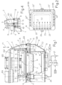
- the number 1 indicates the upper housing which is provided in its lower part with inner annular edges 101, 101' and an outer edge 201 which surrounds said inner edges and which, together with the latter, delimits an annular chamber 2 which communicates, through apertures 3 suitably distributed along the edge 101, with the inner volume 102 of the housing 1, which is connected to suitable vertical guiding and raising and lowering means which are indicated schematically by the double arrow F1 but are not illustrated in detail since they are already known.
- housing 1 there is a plate 4 of a known type connected to special means 104 for selective raising and lowering, which, by means of respective interposed guide and spring means 105, support heat-welding units 5 beneath them and carry cutting units 6 which surround the outside of each welding unit 5 and are normally retracted from the latter.
- the housings shown in Figure 1 are such that they can operate simultaneously on two parallel lines of trays V and V', but only the part intended to operate on a line of trays V has been depicted in a substantially complete way, although it is to be understood that the part of the housing intended for operation on the other line of trays V' is a mirror image of that illustrated and is identical thereto in all respects.
- the protective scope of the invention also includes housings which can operate on a single line of trays or on a single tray, for which the edge 101' will be placed adjacent to an outer edge 201.
- the number 100 indicates known means for damping the closure of the upper housing 1 onto the aforesaid lower housing.
- the heat-welding film H passes under the housing 1 and is used to seal the preformed trays V filled with the product M, the trays being placed by any suitable means under the housing 1 and accurately centred with respect to said means 5 and 6, while also bearing on extractors 7 of a known type associated with the lower housing 8 with corresponding guide and movement means 107.
- the lower housing 8 is connected to suitable known raising and lowering means indicated schematically by the double arrow F2, and has a chamber 9 whose shape and size are such that it can house the extractor 7 with the tray V when the housing is raised (see below), this chamber being provided at its top with a seat 10 having an annular opening, usually with a non-stick gasket 110, on which the lower part of the edge B of the tray V is intended to bear in a sealed way.
- the lower housing 8 has flat surfaces 11, 11' with annularly continuous gaskets 12 and 13, aligned with and facing the edges 101, 101' and 201 of the upper housing 1.
- annular recess 14 having suitable characteristics, while the portion of the flat surface 11 lying between said gaskets 12 and 13 has vertical apertures 15 in the form of holes or slots communicating with the underlying chamber 109 which is connected to the chamber 9 through lateral apertures 16 of the lower housing 8, and communicating with the inner chamber 2 of the upper housing 1 which lies above when the two housings are closed as shown in Figure 1 (see below).
- the chamber 9 has an opening with a conduit 17 which can be connected to or disconnected from a vacuum pump 21 by means of a shut-off unit with valve means 18, controlled by a processor 19.
- the number 20 indicates a unit for programming, and if necessary for interrogating and controlling, the processor 19 and the unit 18 connected thereto.
- the recess 14 surrounding the annular seat 10 has holes and/or slots on its four sides, arranged in at least two opposing rows Z of holes 22, 22' or preferably in four rows as also indicated by supplementary holes 22", these last rows of holes 22" being connected to the rows of holes 22' and being connected, together with these, to the inner circuit 9, 109 of the housings 1, 8.
- the rows of holes 22 are connected to a manifold 23 of any suitable type, which is located inside the housing 8 and which is connected by means of one or more conduit(s) 24 to the shut-off unit 18 to which the means 25 for supplying the process gases to be injected into the trays are also connected.
- the apparatus operates in the following way.
- the apparatus is in the condition shown in Figure 1 .
- the tray V with the product bears with its edge B on the gasket 110 of the annular seat 10, the housings 1 and 8 are closed onto each other, with the edges 101, 101' and 201 interacting with the annular gaskets 12 and 13 and with a portion of film H clamped between the gasket 12 and said edges 101, 101' and suitably raised above the edge B of the tray.
- conduits 17 and 24 are connected through the unit 18 of Figure 1 to the pump 21 which thus draws air both from the inside of the tray, through all the holes 22, 22', 22", and from the chambers 9, 109 of the lower housing, as well as from the chambers 2, 102 of the upper housing, in such a way that the pressures on the opposing faces of the film H are equal and the arrangement of the film in space is not substantially changed.
- the conduit 17 is, for example, closed by the unit 18 in the connection to the pump 21, which, for example, is switched off (see below), and, at the correct time, the unit 18 connects the conduit 24 to the source 25 supplying the process gases which, as indicated by the arrows Z in Figure 2 , enter the tray V through the row of holes 22 and create a saturation front which advances in a uniform laminar way, without any development of turbulence, thus forcing the residual air in the tray to flow out through the rows of holes 22" and 22' and to enter the chambers 9, 109, 2, 102 of the housings where there is a low vacuum.
- the amount of gas entering the tray is equal to the amount of air leaving it and entering the inner chambers of the housings, and therefore the pressure on the opposite faces of the film H is substantially balanced.
- the welding means 5 are lowered as shown in Figure 4 to fasten the film in a gas-tight way, and at the correct time the unit 18 shuts off the connection of the conduit 24 to the process gas supply source 25.
- the treatment gases rapidly saturate the inner space of the tray containing the product to be packaged, and remain trapped therein after said step of welding the film H onto the edge of the tray.
- This step is immediately followed by the step in which the film is cut, by the lowering of the means 6 which partially enter the annular recess 14, after which the inner chambers of the housings are brought to atmospheric pressure, the means 5 and 6 are raised, the housings are moved away from each other, the extractor 7 raises the packaged tray from the seat 10, and known means come into operation in order to remove the sealed trays, to replace them with new trays to be sealed, to advance the film H, to remove the waste part of the film and move it towards collection means, and to provide a new intact portion of the same film above the new trays to be sealed.
- FIG. 5 show the interaction of the vacuum or suction step A, the gas injection step G and the welding step S in the prior art.
- the long amount of time elapsing in the step in which the suction A is active (position 1) is additional to the subsequent time in which the gas injection step G is active, and therefore when the welding step S is activated the total time taken for treating the inner volume of the tray to be sealed is the sum of the two aforesaid time intervals, which is equal to T1.
- Figure 6 shows that the time T2 for treating the inner volume of the tray to be sealed can be reduced considerably with the apparatus according to the invention, since the active time of the vacuum step A is reduced and partially overlaps with the gas injection step G, as described above.
- the supplementary holes 22" in the shorter sides of the tray can be provided in a limited number and/or in an arrangement closer to the row of holes 22' than to the row of holes 22, or can be provided with a different geometry and/or shape.
- the variant illustrated in Figure 3 shows that the rows of holes 22" can be connected to corresponding manifolds 23' to which their conduits 24' are connected. In the vacuum formation step, all the holes 22, 22' and 22" are in suction mode. However, when the gas injection step commences, the holes 22 are connected to the gas source, while the holes 22" are closed or modified by, or in, connection with the outlet holes 22'.
- Simple means located behind the corresponding conduits 24' can be used to close or constrict said rows of holes 22" automatically, in such a way that the process gases flow from the holes 22 solely or predominantly towards the opposing holes 22' as indicated by the arrows Z in Figure 2 , so as to occupy in a uniform way, without any formation of vortices or reflux, the whole extension of the main chamber P containing the film, tray and product.
- the operator can select and set the operating cycle which is most suitable for the packaging of the products in the trays at any given time, given that, inaddition to the indicated cycles, the machine can execute packaging cycles with a vacuum only or nor-mal packaging cycles.
Landscapes
- Engineering & Computer Science (AREA)
- Mechanical Engineering (AREA)
- Chemical & Material Sciences (AREA)
- Dispersion Chemistry (AREA)
- Vacuum Packaging (AREA)
- Closing Of Containers (AREA)
- Containers And Plastic Fillers For Packaging (AREA)
Claims (3)
- Verfahren zum Verpacken von in Verpackungsschalen eingelegten Produkten unter modifizierter Atmosphäre, unter Verwendung einer Vorrichtung von der Bauart mit einem nach unten offenen, oberen Gehäuse (1), enthaltend das Schweißmittel (5) und vorzugsweise auch das Mittel (6) zum Schneiden der Barrierefolie (H) für das Versiegeln der Verpackungsschalen, sowie mit einem nach oben offenen, unteren Gehäuse (8) mit einer Kammer (9), die wenigstens eine ringförmige Aufnahme (10) zur Beherbergung einer Verpackungsschale (V) aufweist, welche in die ringförmige Aufnahme (10) hinein und aus dieser heraus bewegt werden kann, sowie mit einem Mittel zum Positionieren eines aufgespannten Bereichs der Folie (H) zwischen den zwei Gehäusen (1, 8) und oberhalb der Verpackungsschalen (V), als auch mit einem Mittel zum Zusammenbringen der besagten Gehäuse, um zwischen jenen die besagte Folie oberhalb der Kanten der Verpackungsschale (V) einzuklemmen, und auch mit einem Mittel, das zum richtigen Zeitpunkt Prozessgase in die Verpackungsschale injiziert, um das in die Verpackungsschale eingelegte Produkt zu konservieren, vor dem nachfolgenden Schritt des Anschweißens der Folie an die Kante der Verpackungsschale, und dem darauffolgenden Schneiden entlang des Umfangs des an die Kante der Verpackungsschale aufgeschweißten Folienbereichs, wobei ein Mittel vorgesehen ist, welches derart arbeitet, dass die besagten Gehäuse (1, 8) innen eine Hauptkammer (P) bilden, die oben von der Folie (H) zum Bedecken der Verpackungsschale begrenzt wird, und unten von der das Produkt (M) enthaltenden Verpackungsschale (V), sowie seitlich von jeder geeigneten mechanischen Schnittstellenstruktur, die den Umfang der besagten Folie umgibt und diesen mit dem Umfang der oberen Kante (B) der Verpackungsschale verbindet, wobei diese Schnittstellenstruktur mit Löchern und/oder Schlitzen (22) versehen ist, die in geeigneter Weise verteilt sind und sich außerhalb des Umfangs der Verpackungsschale befinden und mit der besagten Hauptkammer (P) kommunizieren, wobei sich eines oder mehrere dieser Löcher (22) substantiell in einem ersten Bereich oder an einer Seite der Verpackungsschale öffnen und an einen ersten Kreislauf (23, 24) angeschlossen sind, während sich eines oder mehrere andere (22') der besagten Löcher in wenigstens einem zweiten gegenüberliegenden Bereich oder an einer gegenüberliegenden Seite der Verpackungsschale öffnen und an einen zweiten Kreislauf (17) angeschlossen ist/sind, dadurch gekennzeichnet, dass der zweite Kreislauf an den inneren Kammern der zwei Gehäuse (1, 8) angeschlossen ist, und dadurch, dass Mittel (18, 19, 20) bereitgestellt sind, um so zu agieren, dass während eines Evakuierungsschrittes zum richtigen Zeitpunkt Luft aus der Verpackungsschale extrahiert wird, wobei der Evakuierungsschritt einem Schritt der Injektion von Prozessgases vorausgeht, und wobei in dem Evakuierungsschritt sowohl der besagte erste Kreislauf (24) als auch der besagte zweite Kreislauf (17) mit dem Evakuierungsmittel (21) verbunden ist, und für eine ausreichende Zeit in einem aktiven Zustand gehalten werden, damit 30 - 50 % der Luft aus dem inneren der Verpackungsschale entfernt wird, und um so zu arbeiten, dass in dem nächsten Schritt oder zum richtigen Zeitpunkt der besagte erste Kreislauf (24) an das Mittel (25) für die Zufuhr von Prozessgas angeschlossen wird, während der besagte zweite Kreislauf (17) geschlossen wird oder mit dem Evakuierungsmittel (21) in einer derartigen Weise verbunden bleibt, dass das Prozessgas, das durch den ersten Kreislauf (22, 24) in einen Teil der Verpackungsschale strömt, die in der Verpackungsschale verbliebene Luft veranlasst, durch den zweiten Kreislauf (22', 17) aus der Verpackungsschale heraus und/oder zu wenigstens einem gegenüberliegenden Teil der Verpackungsschale zu fließen, wobei die Gesamtanordnung derart getroffen ist, dass das innere Volumen der Verpackungsschale gleichzeitig gespült und gesättigt wird, wobei auf diese Weise die gesamte Ausdehnung der besagten Hauptkammer (P), umfassend die Folie, die Verpackungsschale und das Produkt, das anschließend unter Verwendung bekannter Schritte und Mittel zum Schweißen und endgültigen Abschneiden der Folie (H) versiegelt wird, ohne Wirbelbildung oder Rückstrom und somit schnell und zuverlässig gleichförmig ausgefüllt wird, und auch gekennzeichnet durch die Tatsache, dass in der besagten Schnittstellenstruktur eine ringförmige Ausnehmung (14) vorhanden ist, welche die ringförmige Aufnahme (10) umgibt sowie an ihren vier Seiten Löcher und/oder Schlitze aufweist, welche die besagten gegenüber liegenden Löcher (22, 22') und zusätzlichen Öffnungen und/oder Schlitze (22") umfassen, welche entsprechend den anderen zwei Seiten der Verpackungsschale offen sind, wobei die besagten zusätzlichen Öffnungen (22") mit der inneren Kammer (9, 109) des unteren Gehäuses (8) unter Zwischenschaltung kontrollierter Absperrmittel in Verbindung stehen, wobei die komplette Anordnung derart ist, dass in dem Schritt der Vakuumbildung die zusätzlichen Öffnungen (22") ebenfalls aktiv sind, während in dem Schritt der Gaseinspritzung die zusätzlichen Öffnungen (22") derart geschlossen oder verengt sind, dass die Luft aus der Hauptkammer (P), welche die Verpackungsschale enthält, allein oder überwiegend durch diejenigen Löcher (22') hinausströmt, welche den Löchern (22) für den Zufluss des Prozessgases gegenüber liegen.
- Verfahren gemäß Anspruch 1, wobei die besagte mechanische Schnittstellenstruktur einen Teil des unteren Gehäuses (8) bildet und eine ringförmige Aufnahme (10, 110) aufweist, die dazu geeignet ist, die Verpackungsschale (V, M) zu fassen und sie an ihren Kanten (B) zu unterstützen, und wobei sie eine ringförmige flache Oberfläche (11, 11') aufweist, welche die besagte Aufnahme (10) umgibt und deren Oberseite auf einem höheren Niveau liegt als diese Aufnahme (10), und welche Dichtungsringe (12, 13) aufweist, an welchen die unteren Kanten (101, 101', 201) des oberen Gehäuses (1) in einer dichtenden Weise anliegen, wenn das obere Gehäuse über das untere Gehäuse geschlossen wird, unter Einfügung der Folie (H), welche solchermaßen auf geeignete Weise über die Kante der Verpackungsschale angehoben wird, um die besagte Hauptkammer (P) zu bilden, wobei die ringförmige Ausnehmung (14) zwischen der besagten Aufnahme (10, 110) und der besagten ringförmigen flachen Oberfläche (11, 11") vorgesehen ist und die besagten, sich da hinein öffnenden Löcher und/oder Schlitze (22, 22', 22") aufweist, durch welche die Hauptkammer (P) mit dem besagten Evakuierungsmittel (21) und/oder mit dem besagten Mittel (25) für die Zufuhr von Prozessgas verbunden werden kann.
- Verfahren gemäß Anspruch 1, wobei der besagte erste Kreislauf (24) an einem Verteiler (23) angeschlossen ist, der sich im inneren des unteren Gehäuses (8) befindet und welcher an den besagten Löchern (22) angeschlossen ist, die sich an der ersten Seite der Verpackungsschale öffnen, während der besagte zweite Kreislauf (17) mit den inneren Kammern (9, 109) des unteren Gehäuses (8) kommuniziert, welche direkt an den Löchern (22') angeschlossen sind, die sich an der zweiten, gegenüber liegenden Seite der Verpackungsschale öffnen, wobei die besagten ersten und zweiten Kreisläufe (24, 17) an einer Absperreinheit mit Ventilen (18) angeschlossen sind, die von einem Prozessor (19) mit einem Programmierterminal (20) gesteuert werden und an dem besagten Evakuierungsmittel (21) sowie an dem besagten Mittel (25) für die Zufuhr von Prozessgas angeschlossen sind.
Applications Claiming Priority (2)
| Application Number | Priority Date | Filing Date | Title |
|---|---|---|---|
| ITBO2010A000211A IT1399314B1 (it) | 2010-04-08 | 2010-04-08 | Apparato a campane contrapposte, per il confezionamento in atmosfera modificata di prodotti posti in vassoi. |
| PCT/EP2011/055200 WO2011124548A1 (en) | 2010-04-08 | 2011-04-04 | Apparatus with opposing housings for modified atmosphere packaging of products placed in trays |
Publications (3)
| Publication Number | Publication Date |
|---|---|
| EP2555981A1 EP2555981A1 (de) | 2013-02-13 |
| EP2555981B1 EP2555981B1 (de) | 2018-06-27 |
| EP2555981B2 true EP2555981B2 (de) | 2024-10-09 |
Family
ID=43067156
Family Applications (1)
| Application Number | Title | Priority Date | Filing Date |
|---|---|---|---|
| EP11713735.6A Active EP2555981B2 (de) | 2010-04-08 | 2011-04-04 | Verfahren zum verpacken von in verpackungsschalen eingelegten produkten unter modifizierter atmosphäre |
Country Status (11)
| Country | Link |
|---|---|
| US (1) | US9555910B2 (de) |
| EP (1) | EP2555981B2 (de) |
| AU (1) | AU2011237995B2 (de) |
| BR (1) | BR112012025454A2 (de) |
| CA (1) | CA2795283C (de) |
| ES (1) | ES2685463T5 (de) |
| IL (1) | IL222261A (de) |
| IT (1) | IT1399314B1 (de) |
| NZ (1) | NZ602717A (de) |
| RU (1) | RU2012147453A (de) |
| WO (1) | WO2011124548A1 (de) |
Families Citing this family (12)
| Publication number | Priority date | Publication date | Assignee | Title |
|---|---|---|---|---|
| IT1397823B1 (it) * | 2010-01-26 | 2013-02-04 | Gruppo Fabbri S P A | Apparato per il confezionamento in atmosfera modificata di prodotti posti in vassoi. |
| DE102012005891A1 (de) * | 2012-03-23 | 2013-09-26 | Multivac Sepp Haggenmüller Gmbh & Co. Kg | Verpackungsmaschine mit Siegelstation zum Begasen einer Verpackung |
| ITBO20120549A1 (it) | 2012-10-09 | 2014-04-10 | Gruppo Fabbri Vignola Spa | Apparato a campane contrapposte, per il confezionamento in atmosfera modificata di prodotti posti in vassoi |
| ES2669597T3 (es) * | 2015-05-21 | 2018-05-28 | Multivac Sepp Haggenmüller Se & Co. Kg | Máquina cerradora de barquetas |
| ES2824455T3 (es) * | 2017-08-30 | 2021-05-12 | Multivac Haggenmueller Kg | Estación de sellado así como procedimiento para la producción de embalajes de película con esquina de apertura |
| DE102018110227A1 (de) * | 2018-04-27 | 2019-10-31 | Multivac Sepp Haggenmüller Se & Co. Kg | Verpackungsmaschine zum Verpacken von Produkten in Kunststoffverpackungen |
| DE102018114263A1 (de) * | 2018-06-14 | 2019-12-19 | Multivac Sepp Haggenmüller Se & Co. Kg | Füllstandsunabhängiges begasen |
| US12122584B2 (en) | 2020-08-27 | 2024-10-22 | Sonoco Development, Inc. | Container assemblies with paper-based end closures |
| EP4182160A1 (de) * | 2020-08-27 | 2023-05-24 | Sonoco Development, Inc. | Systeme und verfahren zum anbringen und abdichten von endverschlüssen an behältern |
| DE102021134192A1 (de) | 2021-12-22 | 2023-06-22 | Multivac Sepp Haggenmüller Se & Co. Kg | Siegelstation zum Versiegeln von Verpackungen |
| US12391422B1 (en) * | 2022-09-06 | 2025-08-19 | Amazon Technologies, Inc. | Sealing mechanism with punches and dies for securing packages |
| DE102023121207A1 (de) * | 2023-08-09 | 2025-02-13 | Multivac Sepp Haggenmüller Se & Co. Kg | Verfahren zum Schutzbegasen einer Verpackung sowie Begasungsstation |
Family Cites Families (21)
| Publication number | Priority date | Publication date | Assignee | Title |
|---|---|---|---|---|
| US3481100A (en) | 1966-11-23 | 1969-12-02 | Anderson Bros Mfg Co | Method and apparatus for packaging in protective atmosphere |
| US3708949A (en) * | 1969-02-04 | 1973-01-09 | Safeway Stores | Method and apparatus for detection of leaks in seals of packages |
| US3992850A (en) | 1973-05-09 | 1976-11-23 | Multivac Sepp Haggenmueller Kg | Apparatus for packing materials in synthetic foils |
| US5323590A (en) * | 1986-09-03 | 1994-06-28 | Seawell North America, Inc. | Method of producing food packaging with gas between tensioned film and lid |
| US5534282A (en) * | 1989-08-30 | 1996-07-09 | Seawell North America Inc. | Packing perishable goods |
| IT1244845B (it) | 1990-11-22 | 1994-09-06 | Mondini G Spa | Macchina confezionatrice per la sigillatura di contenitori |
| US5398481A (en) * | 1992-05-19 | 1995-03-21 | Ebara Corporation | Vacuum processing system |
| US5271207A (en) * | 1992-11-18 | 1993-12-21 | Moshe Epstein | Dual-function nozzle head for vacuum-packaging tooling |
| US6305149B1 (en) * | 1993-11-18 | 2001-10-23 | Marlen Research Corporation | Method and apparatus for packaging meat |
| US7205016B2 (en) * | 1997-03-13 | 2007-04-17 | Safefresh Technologies, Llc | Packages and methods for processing food products |
| AU1893399A (en) * | 1997-12-24 | 1999-07-19 | Sealed Air New Zealand Limited | Methods and apparatus for providing a modified atmosphere in a package |
| DE10237933A1 (de) * | 2002-08-14 | 2004-02-26 | Multivac Sepp Haggenmüller Gmbh & Co. Kg | Verfahren und Verpackungsmaschine zum Verpacken eines in einer Schale befindlichen Produktes |
| US6976347B2 (en) * | 2002-09-13 | 2005-12-20 | Alkar-Rapidpak, Inc. | Surface pasteurization method |
| US6834476B2 (en) * | 2002-10-17 | 2004-12-28 | Ibaraki Seiki Machinery Company, Ltd. | Sealing and packaging device for cover film on tray |
| TWM273530U (en) | 2005-01-21 | 2005-08-21 | Biedermi Entpr Co Ltd | Vacuum gas flushing seal packaging machine for box |
| ITBO20060249A1 (it) * | 2006-04-05 | 2007-10-06 | Awax Progettazione | Apparato e macchina per confezionare vaschette di prodotti in atmosfera modificata. |
| DE102007047058A1 (de) * | 2006-10-06 | 2008-04-10 | Multivac Sepp Haggenmüller Gmbh & Co. Kg | Abdichtleiste |
| EP1932763A1 (de) | 2006-11-21 | 2008-06-18 | CFS Bühl GmbH | Verpackungsmaschine für MAP- und Skinverpackungen |
| IT1397823B1 (it) | 2010-01-26 | 2013-02-04 | Gruppo Fabbri S P A | Apparato per il confezionamento in atmosfera modificata di prodotti posti in vassoi. |
| WO2013001482A1 (en) * | 2011-06-28 | 2013-01-03 | Dynamic Micro Systems | Semiconductor stocker systems and methods. |
| DE102012005891A1 (de) * | 2012-03-23 | 2013-09-26 | Multivac Sepp Haggenmüller Gmbh & Co. Kg | Verpackungsmaschine mit Siegelstation zum Begasen einer Verpackung |
-
2010
- 2010-04-08 IT ITBO2010A000211A patent/IT1399314B1/it active
-
2011
- 2011-04-04 EP EP11713735.6A patent/EP2555981B2/de active Active
- 2011-04-04 RU RU2012147453/13A patent/RU2012147453A/ru not_active Application Discontinuation
- 2011-04-04 AU AU2011237995A patent/AU2011237995B2/en active Active
- 2011-04-04 CA CA2795283A patent/CA2795283C/en active Active
- 2011-04-04 ES ES11713735T patent/ES2685463T5/es active Active
- 2011-04-04 BR BR112012025454A patent/BR112012025454A2/pt not_active IP Right Cessation
- 2011-04-04 NZ NZ602717A patent/NZ602717A/en unknown
- 2011-04-04 WO PCT/EP2011/055200 patent/WO2011124548A1/en not_active Ceased
- 2011-04-04 US US13/639,990 patent/US9555910B2/en active Active
-
2012
- 2012-10-09 IL IL222261A patent/IL222261A/en active IP Right Grant
Also Published As
| Publication number | Publication date |
|---|---|
| IT1399314B1 (it) | 2013-04-16 |
| RU2012147453A (ru) | 2014-05-20 |
| ES2685463T3 (es) | 2018-10-09 |
| WO2011124548A1 (en) | 2011-10-13 |
| CA2795283C (en) | 2018-08-21 |
| EP2555981A1 (de) | 2013-02-13 |
| IL222261A (en) | 2017-11-30 |
| EP2555981B1 (de) | 2018-06-27 |
| AU2011237995B2 (en) | 2015-05-07 |
| ES2685463T5 (en) | 2025-02-13 |
| CA2795283A1 (en) | 2011-10-13 |
| NZ602717A (en) | 2014-07-25 |
| US20130036706A1 (en) | 2013-02-14 |
| US9555910B2 (en) | 2017-01-31 |
| AU2011237995A1 (en) | 2012-10-25 |
| ITBO20100211A1 (it) | 2011-10-09 |
| BR112012025454A2 (pt) | 2016-07-05 |
Similar Documents
| Publication | Publication Date | Title |
|---|---|---|
| EP2555981B2 (de) | Verfahren zum verpacken von in verpackungsschalen eingelegten produkten unter modifizierter atmosphäre | |
| EP2729373B1 (de) | Vorrichtung mit gegenüberliegenden glockenförmigen elementen zur verpackung von in schalen enthaltenen produkten in einer modifizierten atmosphäre | |
| EP2528827B1 (de) | Vorrichtung zum verpacken von in schalen eingelegten produkten unter modifizierter atmosphäre | |
| CA2872657C (en) | Apparatus with facing bell members, for modified atmosphere packaging of products placed in trays | |
| US20080104930A1 (en) | Sealing bar | |
| CN104627926A (zh) | 用于向物品填充可倾倒的产品的填充单元及填充方法 | |
| EP4313777B1 (de) | Vakuumverpackungsmaschine vom riementyp | |
| JP5174557B2 (ja) | 真空・ガス置換包装装置 | |
| US12064926B2 (en) | Packaging device | |
| JP2019011130A (ja) | 注入可能製品を物品に充填するための充填ユニットおよび方法 | |
| JP3092768U (ja) | 真空包装体を連続形成する装置 |
Legal Events
| Date | Code | Title | Description |
|---|---|---|---|
| PUAI | Public reference made under article 153(3) epc to a published international application that has entered the european phase |
Free format text: ORIGINAL CODE: 0009012 |
|
| 17P | Request for examination filed |
Effective date: 20121030 |
|
| AK | Designated contracting states |
Kind code of ref document: A1 Designated state(s): AL AT BE BG CH CY CZ DE DK EE ES FI FR GB GR HR HU IE IS IT LI LT LU LV MC MK MT NL NO PL PT RO RS SE SI SK SM TR |
|
| DAX | Request for extension of the european patent (deleted) | ||
| 17Q | First examination report despatched |
Effective date: 20160527 |
|
| STAA | Information on the status of an ep patent application or granted ep patent |
Free format text: STATUS: EXAMINATION IS IN PROGRESS |
|
| GRAP | Despatch of communication of intention to grant a patent |
Free format text: ORIGINAL CODE: EPIDOSNIGR1 |
|
| STAA | Information on the status of an ep patent application or granted ep patent |
Free format text: STATUS: GRANT OF PATENT IS INTENDED |
|
| INTG | Intention to grant announced |
Effective date: 20180108 |
|
| GRAS | Grant fee paid |
Free format text: ORIGINAL CODE: EPIDOSNIGR3 |
|
| GRAA | (expected) grant |
Free format text: ORIGINAL CODE: 0009210 |
|
| STAA | Information on the status of an ep patent application or granted ep patent |
Free format text: STATUS: THE PATENT HAS BEEN GRANTED |
|
| AK | Designated contracting states |
Kind code of ref document: B1 Designated state(s): AL AT BE BG CH CY CZ DE DK EE ES FI FR GB GR HR HU IE IS IT LI LT LU LV MC MK MT NL NO PL PT RO RS SE SI SK SM TR |
|
| REG | Reference to a national code |
Ref country code: GB Ref legal event code: FG4D |
|
| REG | Reference to a national code |
Ref country code: AT Ref legal event code: REF Ref document number: 1012081 Country of ref document: AT Kind code of ref document: T Effective date: 20180715 |
|
| REG | Reference to a national code |
Ref country code: IE Ref legal event code: FG4D |
|
| REG | Reference to a national code |
Ref country code: DE Ref legal event code: R096 Ref document number: 602011049542 Country of ref document: DE |
|
| REG | Reference to a national code |
Ref country code: ES Ref legal event code: FG2A Ref document number: 2685463 Country of ref document: ES Kind code of ref document: T3 Effective date: 20181009 |
|
| PG25 | Lapsed in a contracting state [announced via postgrant information from national office to epo] |
Ref country code: FI Free format text: LAPSE BECAUSE OF FAILURE TO SUBMIT A TRANSLATION OF THE DESCRIPTION OR TO PAY THE FEE WITHIN THE PRESCRIBED TIME-LIMIT Effective date: 20180627 Ref country code: NO Free format text: LAPSE BECAUSE OF FAILURE TO SUBMIT A TRANSLATION OF THE DESCRIPTION OR TO PAY THE FEE WITHIN THE PRESCRIBED TIME-LIMIT Effective date: 20180927 Ref country code: LT Free format text: LAPSE BECAUSE OF FAILURE TO SUBMIT A TRANSLATION OF THE DESCRIPTION OR TO PAY THE FEE WITHIN THE PRESCRIBED TIME-LIMIT Effective date: 20180627 Ref country code: SE Free format text: LAPSE BECAUSE OF FAILURE TO SUBMIT A TRANSLATION OF THE DESCRIPTION OR TO PAY THE FEE WITHIN THE PRESCRIBED TIME-LIMIT Effective date: 20180627 Ref country code: BG Free format text: LAPSE BECAUSE OF FAILURE TO SUBMIT A TRANSLATION OF THE DESCRIPTION OR TO PAY THE FEE WITHIN THE PRESCRIBED TIME-LIMIT Effective date: 20180927 |
|
| REG | Reference to a national code |
Ref country code: NL Ref legal event code: MP Effective date: 20180627 |
|
| REG | Reference to a national code |
Ref country code: LT Ref legal event code: MG4D |
|
| PG25 | Lapsed in a contracting state [announced via postgrant information from national office to epo] |
Ref country code: LV Free format text: LAPSE BECAUSE OF FAILURE TO SUBMIT A TRANSLATION OF THE DESCRIPTION OR TO PAY THE FEE WITHIN THE PRESCRIBED TIME-LIMIT Effective date: 20180627 Ref country code: RS Free format text: LAPSE BECAUSE OF FAILURE TO SUBMIT A TRANSLATION OF THE DESCRIPTION OR TO PAY THE FEE WITHIN THE PRESCRIBED TIME-LIMIT Effective date: 20180627 Ref country code: GR Free format text: LAPSE BECAUSE OF FAILURE TO SUBMIT A TRANSLATION OF THE DESCRIPTION OR TO PAY THE FEE WITHIN THE PRESCRIBED TIME-LIMIT Effective date: 20180928 Ref country code: HR Free format text: LAPSE BECAUSE OF FAILURE TO SUBMIT A TRANSLATION OF THE DESCRIPTION OR TO PAY THE FEE WITHIN THE PRESCRIBED TIME-LIMIT Effective date: 20180627 |
|
| REG | Reference to a national code |
Ref country code: AT Ref legal event code: MK05 Ref document number: 1012081 Country of ref document: AT Kind code of ref document: T Effective date: 20180627 |
|
| PG25 | Lapsed in a contracting state [announced via postgrant information from national office to epo] |
Ref country code: NL Free format text: LAPSE BECAUSE OF FAILURE TO SUBMIT A TRANSLATION OF THE DESCRIPTION OR TO PAY THE FEE WITHIN THE PRESCRIBED TIME-LIMIT Effective date: 20180627 |
|
| PG25 | Lapsed in a contracting state [announced via postgrant information from national office to epo] |
Ref country code: EE Free format text: LAPSE BECAUSE OF FAILURE TO SUBMIT A TRANSLATION OF THE DESCRIPTION OR TO PAY THE FEE WITHIN THE PRESCRIBED TIME-LIMIT Effective date: 20180627 Ref country code: IS Free format text: LAPSE BECAUSE OF FAILURE TO SUBMIT A TRANSLATION OF THE DESCRIPTION OR TO PAY THE FEE WITHIN THE PRESCRIBED TIME-LIMIT Effective date: 20181027 Ref country code: PL Free format text: LAPSE BECAUSE OF FAILURE TO SUBMIT A TRANSLATION OF THE DESCRIPTION OR TO PAY THE FEE WITHIN THE PRESCRIBED TIME-LIMIT Effective date: 20180627 Ref country code: SK Free format text: LAPSE BECAUSE OF FAILURE TO SUBMIT A TRANSLATION OF THE DESCRIPTION OR TO PAY THE FEE WITHIN THE PRESCRIBED TIME-LIMIT Effective date: 20180627 Ref country code: AT Free format text: LAPSE BECAUSE OF FAILURE TO SUBMIT A TRANSLATION OF THE DESCRIPTION OR TO PAY THE FEE WITHIN THE PRESCRIBED TIME-LIMIT Effective date: 20180627 Ref country code: CZ Free format text: LAPSE BECAUSE OF FAILURE TO SUBMIT A TRANSLATION OF THE DESCRIPTION OR TO PAY THE FEE WITHIN THE PRESCRIBED TIME-LIMIT Effective date: 20180627 Ref country code: RO Free format text: LAPSE BECAUSE OF FAILURE TO SUBMIT A TRANSLATION OF THE DESCRIPTION OR TO PAY THE FEE WITHIN THE PRESCRIBED TIME-LIMIT Effective date: 20180627 |
|
| PG25 | Lapsed in a contracting state [announced via postgrant information from national office to epo] |
Ref country code: SM Free format text: LAPSE BECAUSE OF FAILURE TO SUBMIT A TRANSLATION OF THE DESCRIPTION OR TO PAY THE FEE WITHIN THE PRESCRIBED TIME-LIMIT Effective date: 20180627 |
|
| REG | Reference to a national code |
Ref country code: DE Ref legal event code: R026 Ref document number: 602011049542 Country of ref document: DE |
|
| PLBI | Opposition filed |
Free format text: ORIGINAL CODE: 0009260 |
|
| PLAX | Notice of opposition and request to file observation + time limit sent |
Free format text: ORIGINAL CODE: EPIDOSNOBS2 |
|
| 26 | Opposition filed |
Opponent name: MULTIVAC SEPP HAGGENMUELLER SE & CO. KG Effective date: 20190326 |
|
| PG25 | Lapsed in a contracting state [announced via postgrant information from national office to epo] |
Ref country code: DK Free format text: LAPSE BECAUSE OF FAILURE TO SUBMIT A TRANSLATION OF THE DESCRIPTION OR TO PAY THE FEE WITHIN THE PRESCRIBED TIME-LIMIT Effective date: 20180627 |
|
| PLAF | Information modified related to communication of a notice of opposition and request to file observations + time limit |
Free format text: ORIGINAL CODE: EPIDOSCOBS2 |
|
| PG25 | Lapsed in a contracting state [announced via postgrant information from national office to epo] |
Ref country code: SI Free format text: LAPSE BECAUSE OF FAILURE TO SUBMIT A TRANSLATION OF THE DESCRIPTION OR TO PAY THE FEE WITHIN THE PRESCRIBED TIME-LIMIT Effective date: 20180627 |
|
| PLBB | Reply of patent proprietor to notice(s) of opposition received |
Free format text: ORIGINAL CODE: EPIDOSNOBS3 |
|
| PG25 | Lapsed in a contracting state [announced via postgrant information from national office to epo] |
Ref country code: AL Free format text: LAPSE BECAUSE OF FAILURE TO SUBMIT A TRANSLATION OF THE DESCRIPTION OR TO PAY THE FEE WITHIN THE PRESCRIBED TIME-LIMIT Effective date: 20180627 |
|
| REG | Reference to a national code |
Ref country code: CH Ref legal event code: PL |
|
| REG | Reference to a national code |
Ref country code: BE Ref legal event code: MM Effective date: 20190430 |
|
| PG25 | Lapsed in a contracting state [announced via postgrant information from national office to epo] |
Ref country code: LU Free format text: LAPSE BECAUSE OF NON-PAYMENT OF DUE FEES Effective date: 20190404 Ref country code: MC Free format text: LAPSE BECAUSE OF FAILURE TO SUBMIT A TRANSLATION OF THE DESCRIPTION OR TO PAY THE FEE WITHIN THE PRESCRIBED TIME-LIMIT Effective date: 20180627 |
|
| PG25 | Lapsed in a contracting state [announced via postgrant information from national office to epo] |
Ref country code: CH Free format text: LAPSE BECAUSE OF NON-PAYMENT OF DUE FEES Effective date: 20190430 Ref country code: LI Free format text: LAPSE BECAUSE OF NON-PAYMENT OF DUE FEES Effective date: 20190430 |
|
| PG25 | Lapsed in a contracting state [announced via postgrant information from national office to epo] |
Ref country code: BE Free format text: LAPSE BECAUSE OF NON-PAYMENT OF DUE FEES Effective date: 20190430 |
|
| PG25 | Lapsed in a contracting state [announced via postgrant information from national office to epo] |
Ref country code: TR Free format text: LAPSE BECAUSE OF FAILURE TO SUBMIT A TRANSLATION OF THE DESCRIPTION OR TO PAY THE FEE WITHIN THE PRESCRIBED TIME-LIMIT Effective date: 20180627 |
|
| PG25 | Lapsed in a contracting state [announced via postgrant information from national office to epo] |
Ref country code: IE Free format text: LAPSE BECAUSE OF NON-PAYMENT OF DUE FEES Effective date: 20190404 |
|
| PG25 | Lapsed in a contracting state [announced via postgrant information from national office to epo] |
Ref country code: PT Free format text: LAPSE BECAUSE OF FAILURE TO SUBMIT A TRANSLATION OF THE DESCRIPTION OR TO PAY THE FEE WITHIN THE PRESCRIBED TIME-LIMIT Effective date: 20181029 |
|
| PG25 | Lapsed in a contracting state [announced via postgrant information from national office to epo] |
Ref country code: CY Free format text: LAPSE BECAUSE OF FAILURE TO SUBMIT A TRANSLATION OF THE DESCRIPTION OR TO PAY THE FEE WITHIN THE PRESCRIBED TIME-LIMIT Effective date: 20180627 |
|
| PG25 | Lapsed in a contracting state [announced via postgrant information from national office to epo] |
Ref country code: HU Free format text: LAPSE BECAUSE OF FAILURE TO SUBMIT A TRANSLATION OF THE DESCRIPTION OR TO PAY THE FEE WITHIN THE PRESCRIBED TIME-LIMIT; INVALID AB INITIO Effective date: 20110404 Ref country code: MT Free format text: LAPSE BECAUSE OF FAILURE TO SUBMIT A TRANSLATION OF THE DESCRIPTION OR TO PAY THE FEE WITHIN THE PRESCRIBED TIME-LIMIT Effective date: 20180627 |
|
| APBM | Appeal reference recorded |
Free format text: ORIGINAL CODE: EPIDOSNREFNO |
|
| APBP | Date of receipt of notice of appeal recorded |
Free format text: ORIGINAL CODE: EPIDOSNNOA2O |
|
| APAH | Appeal reference modified |
Free format text: ORIGINAL CODE: EPIDOSCREFNO |
|
| PG25 | Lapsed in a contracting state [announced via postgrant information from national office to epo] |
Ref country code: MK Free format text: LAPSE BECAUSE OF FAILURE TO SUBMIT A TRANSLATION OF THE DESCRIPTION OR TO PAY THE FEE WITHIN THE PRESCRIBED TIME-LIMIT Effective date: 20180627 |
|
| APBQ | Date of receipt of statement of grounds of appeal recorded |
Free format text: ORIGINAL CODE: EPIDOSNNOA3O |
|
| APBU | Appeal procedure closed |
Free format text: ORIGINAL CODE: EPIDOSNNOA9O |
|
| REG | Reference to a national code |
Ref country code: CH Ref legal event code: PK Free format text: BERICHTIGUNGEN |
|
| RIC2 | Information provided on ipc code assigned after grant |
Ipc: B65B 31/04 20060101ALI20240201BHEP Ipc: B65B 31/02 20060101AFI20240201BHEP |
|
| PUAH | Patent maintained in amended form |
Free format text: ORIGINAL CODE: 0009272 |
|
| STAA | Information on the status of an ep patent application or granted ep patent |
Free format text: STATUS: PATENT MAINTAINED AS AMENDED |
|
| 27A | Patent maintained in amended form |
Effective date: 20241009 |
|
| AK | Designated contracting states |
Kind code of ref document: B2 Designated state(s): AL AT BE BG CH CY CZ DE DK EE ES FI FR GB GR HR HU IE IS IT LI LT LU LV MC MK MT NL NO PL PT RO RS SE SI SK SM TR |
|
| REG | Reference to a national code |
Ref country code: DE Ref legal event code: R102 Ref document number: 602011049542 Country of ref document: DE |
|
| REG | Reference to a national code |
Ref country code: ES Ref legal event code: DC2A Ref document number: 2685463 Country of ref document: ES Kind code of ref document: T5 Effective date: 20250213 |
|
| PGFP | Annual fee paid to national office [announced via postgrant information from national office to epo] |
Ref country code: DE Payment date: 20250422 Year of fee payment: 15 |
|
| PGFP | Annual fee paid to national office [announced via postgrant information from national office to epo] |
Ref country code: GB Payment date: 20250423 Year of fee payment: 15 Ref country code: ES Payment date: 20250529 Year of fee payment: 15 |
|
| PGFP | Annual fee paid to national office [announced via postgrant information from national office to epo] |
Ref country code: IT Payment date: 20250408 Year of fee payment: 15 |
|
| PGFP | Annual fee paid to national office [announced via postgrant information from national office to epo] |
Ref country code: FR Payment date: 20250425 Year of fee payment: 15 |