EP2555866B1 - Catalyseur comprenant les zéolithes Cu-CHA et Fe-MFI et procédé DE TRAITEMENT DE NOX DANS DES COURANTS GAZEUX - Google Patents
Catalyseur comprenant les zéolithes Cu-CHA et Fe-MFI et procédé DE TRAITEMENT DE NOX DANS DES COURANTS GAZEUX Download PDFInfo
- Publication number
- EP2555866B1 EP2555866B1 EP11765157.0A EP11765157A EP2555866B1 EP 2555866 B1 EP2555866 B1 EP 2555866B1 EP 11765157 A EP11765157 A EP 11765157A EP 2555866 B1 EP2555866 B1 EP 2555866B1
- Authority
- EP
- European Patent Office
- Prior art keywords
- zeolites
- catalyst
- structure type
- exhaust gas
- cha
- Prior art date
- Legal status (The legal status is an assumption and is not a legal conclusion. Google has not performed a legal analysis and makes no representation as to the accuracy of the status listed.)
- Active
Links
- 239000010457 zeolite Substances 0.000 title claims description 216
- 239000003054 catalyst Substances 0.000 title claims description 203
- 238000000034 method Methods 0.000 title claims description 48
- 230000008569 process Effects 0.000 title claims description 35
- 229910021536 Zeolite Inorganic materials 0.000 title description 73
- HNPSIPDUKPIQMN-UHFFFAOYSA-N dioxosilane;oxo(oxoalumanyloxy)alumane Chemical compound O=[Si]=O.O=[Al]O[Al]=O HNPSIPDUKPIQMN-UHFFFAOYSA-N 0.000 title description 61
- QGZKDVFQNNGYKY-UHFFFAOYSA-N Ammonia Chemical compound N QGZKDVFQNNGYKY-UHFFFAOYSA-N 0.000 claims description 90
- 239000000758 substrate Substances 0.000 claims description 77
- XEEYBQQBJWHFJM-UHFFFAOYSA-N Iron Chemical compound [Fe] XEEYBQQBJWHFJM-UHFFFAOYSA-N 0.000 claims description 56
- 230000003647 oxidation Effects 0.000 claims description 46
- 238000007254 oxidation reaction Methods 0.000 claims description 46
- 229910021529 ammonia Inorganic materials 0.000 claims description 43
- 239000010949 copper Substances 0.000 claims description 34
- 239000010410 layer Substances 0.000 claims description 32
- VYPSYNLAJGMNEJ-UHFFFAOYSA-N Silicium dioxide Chemical compound O=[Si]=O VYPSYNLAJGMNEJ-UHFFFAOYSA-N 0.000 claims description 28
- 238000002485 combustion reaction Methods 0.000 claims description 28
- 229910052802 copper Inorganic materials 0.000 claims description 27
- RYGMFSIKBFXOCR-UHFFFAOYSA-N Copper Chemical compound [Cu] RYGMFSIKBFXOCR-UHFFFAOYSA-N 0.000 claims description 26
- PNEYBMLMFCGWSK-UHFFFAOYSA-N aluminium oxide Inorganic materials [O-2].[O-2].[O-2].[Al+3].[Al+3] PNEYBMLMFCGWSK-UHFFFAOYSA-N 0.000 claims description 20
- 238000011068 loading method Methods 0.000 claims description 18
- XSQUKJJJFZCRTK-UHFFFAOYSA-N Urea Chemical compound NC(N)=O XSQUKJJJFZCRTK-UHFFFAOYSA-N 0.000 claims description 17
- 239000004202 carbamide Substances 0.000 claims description 17
- 239000000377 silicon dioxide Substances 0.000 claims description 14
- 238000011144 upstream manufacturing Methods 0.000 claims description 14
- 239000004071 soot Substances 0.000 claims description 13
- 239000012530 fluid Substances 0.000 claims description 11
- 238000010531 catalytic reduction reaction Methods 0.000 claims description 8
- 238000004891 communication Methods 0.000 claims description 6
- 239000002356 single layer Substances 0.000 claims description 6
- 229910052878 cordierite Inorganic materials 0.000 claims description 5
- JSKIRARMQDRGJZ-UHFFFAOYSA-N dimagnesium dioxido-bis[(1-oxido-3-oxo-2,4,6,8,9-pentaoxa-1,3-disila-5,7-dialuminabicyclo[3.3.1]nonan-7-yl)oxy]silane Chemical compound [Mg++].[Mg++].[O-][Si]([O-])(O[Al]1O[Al]2O[Si](=O)O[Si]([O-])(O1)O2)O[Al]1O[Al]2O[Si](=O)O[Si]([O-])(O1)O2 JSKIRARMQDRGJZ-UHFFFAOYSA-N 0.000 claims description 5
- 229910010271 silicon carbide Inorganic materials 0.000 claims description 5
- HBMJWWWQQXIZIP-UHFFFAOYSA-N silicon carbide Chemical compound [Si+]#[C-] HBMJWWWQQXIZIP-UHFFFAOYSA-N 0.000 claims description 5
- 239000007789 gas Substances 0.000 description 150
- MWUXSHHQAYIFBG-UHFFFAOYSA-N nitrogen oxide Inorganic materials O=[N] MWUXSHHQAYIFBG-UHFFFAOYSA-N 0.000 description 48
- 229910002089 NOx Inorganic materials 0.000 description 36
- 239000003638 chemical reducing agent Substances 0.000 description 25
- 229910052742 iron Inorganic materials 0.000 description 25
- 239000000203 mixture Substances 0.000 description 22
- 238000012360 testing method Methods 0.000 description 15
- 230000000052 comparative effect Effects 0.000 description 12
- 229910052751 metal Inorganic materials 0.000 description 12
- 239000002184 metal Substances 0.000 description 12
- 238000006243 chemical reaction Methods 0.000 description 11
- 229930195733 hydrocarbon Natural products 0.000 description 11
- 150000002430 hydrocarbons Chemical class 0.000 description 11
- JCXJVPUVTGWSNB-UHFFFAOYSA-N nitrogen dioxide Inorganic materials O=[N]=O JCXJVPUVTGWSNB-UHFFFAOYSA-N 0.000 description 11
- IJGRMHOSHXDMSA-UHFFFAOYSA-N Atomic nitrogen Chemical compound N#N IJGRMHOSHXDMSA-UHFFFAOYSA-N 0.000 description 10
- 238000000576 coating method Methods 0.000 description 10
- 239000011248 coating agent Substances 0.000 description 9
- 238000006722 reduction reaction Methods 0.000 description 9
- 239000011230 binding agent Substances 0.000 description 8
- 229910052676 chabazite Inorganic materials 0.000 description 8
- 230000009467 reduction Effects 0.000 description 8
- MCMNRKCIXSYSNV-UHFFFAOYSA-N Zirconium dioxide Chemical compound O=[Zr]=O MCMNRKCIXSYSNV-UHFFFAOYSA-N 0.000 description 7
- 238000001354 calcination Methods 0.000 description 7
- 239000000446 fuel Substances 0.000 description 7
- 239000000463 material Substances 0.000 description 7
- 150000002739 metals Chemical class 0.000 description 7
- GQPLMRYTRLFLPF-UHFFFAOYSA-N Nitrous Oxide Chemical compound [O-][N+]#N GQPLMRYTRLFLPF-UHFFFAOYSA-N 0.000 description 6
- QVGXLLKOCUKJST-UHFFFAOYSA-N atomic oxygen Chemical compound [O] QVGXLLKOCUKJST-UHFFFAOYSA-N 0.000 description 6
- UNYSKUBLZGJSLV-UHFFFAOYSA-L calcium;1,3,5,2,4,6$l^{2}-trioxadisilaluminane 2,4-dioxide;dihydroxide;hexahydrate Chemical compound O.O.O.O.O.O.[OH-].[OH-].[Ca+2].O=[Si]1O[Al]O[Si](=O)O1.O=[Si]1O[Al]O[Si](=O)O1 UNYSKUBLZGJSLV-UHFFFAOYSA-L 0.000 description 6
- 238000001035 drying Methods 0.000 description 6
- 239000001301 oxygen Substances 0.000 description 6
- 229910052760 oxygen Inorganic materials 0.000 description 6
- 239000002002 slurry Substances 0.000 description 6
- 238000003860 storage Methods 0.000 description 6
- 229910045601 alloy Inorganic materials 0.000 description 5
- 239000000956 alloy Substances 0.000 description 5
- 238000004519 manufacturing process Methods 0.000 description 5
- 229910052757 nitrogen Inorganic materials 0.000 description 5
- 239000004215 Carbon black (E152) Substances 0.000 description 4
- PXHVJJICTQNCMI-UHFFFAOYSA-N Nickel Chemical compound [Ni] PXHVJJICTQNCMI-UHFFFAOYSA-N 0.000 description 4
- KDLHZDBZIXYQEI-UHFFFAOYSA-N Palladium Chemical compound [Pd] KDLHZDBZIXYQEI-UHFFFAOYSA-N 0.000 description 4
- 239000000919 ceramic Substances 0.000 description 4
- 239000003344 environmental pollutant Substances 0.000 description 4
- 229910000069 nitrogen hydride Inorganic materials 0.000 description 4
- BASFCYQUMIYNBI-UHFFFAOYSA-N platinum Chemical compound [Pt] BASFCYQUMIYNBI-UHFFFAOYSA-N 0.000 description 4
- 231100000719 pollutant Toxicity 0.000 description 4
- 239000011148 porous material Substances 0.000 description 4
- 239000010970 precious metal Substances 0.000 description 4
- 239000002243 precursor Substances 0.000 description 4
- 239000010936 titanium Substances 0.000 description 4
- 238000005406 washing Methods 0.000 description 4
- GFQYVLUOOAAOGM-UHFFFAOYSA-N zirconium(iv) silicate Chemical compound [Zr+4].[O-][Si]([O-])([O-])[O-] GFQYVLUOOAAOGM-UHFFFAOYSA-N 0.000 description 4
- UGFAIRIUMAVXCW-UHFFFAOYSA-N Carbon monoxide Chemical compound [O+]#[C-] UGFAIRIUMAVXCW-UHFFFAOYSA-N 0.000 description 3
- 229910052782 aluminium Inorganic materials 0.000 description 3
- 229910000323 aluminium silicate Inorganic materials 0.000 description 3
- BVCZEBOGSOYJJT-UHFFFAOYSA-N ammonium carbamate Chemical compound [NH4+].NC([O-])=O BVCZEBOGSOYJJT-UHFFFAOYSA-N 0.000 description 3
- 229910002091 carbon monoxide Inorganic materials 0.000 description 3
- KXDHJXZQYSOELW-UHFFFAOYSA-N carbonic acid monoamide Natural products NC(O)=O KXDHJXZQYSOELW-UHFFFAOYSA-N 0.000 description 3
- 230000003197 catalytic effect Effects 0.000 description 3
- 229910052804 chromium Inorganic materials 0.000 description 3
- 239000011651 chromium Substances 0.000 description 3
- 230000001590 oxidative effect Effects 0.000 description 3
- 229910052719 titanium Inorganic materials 0.000 description 3
- 229910052720 vanadium Inorganic materials 0.000 description 3
- 229910052845 zircon Inorganic materials 0.000 description 3
- 229910000505 Al2TiO5 Inorganic materials 0.000 description 2
- CURLTUGMZLYLDI-UHFFFAOYSA-N Carbon dioxide Chemical compound O=C=O CURLTUGMZLYLDI-UHFFFAOYSA-N 0.000 description 2
- VYZAMTAEIAYCRO-UHFFFAOYSA-N Chromium Chemical compound [Cr] VYZAMTAEIAYCRO-UHFFFAOYSA-N 0.000 description 2
- RTAQQCXQSZGOHL-UHFFFAOYSA-N Titanium Chemical compound [Ti] RTAQQCXQSZGOHL-UHFFFAOYSA-N 0.000 description 2
- 230000001464 adherent effect Effects 0.000 description 2
- XAGFODPZIPBFFR-UHFFFAOYSA-N aluminium Chemical compound [Al] XAGFODPZIPBFFR-UHFFFAOYSA-N 0.000 description 2
- 238000004140 cleaning Methods 0.000 description 2
- 239000002283 diesel fuel Substances 0.000 description 2
- KZHJGOXRZJKJNY-UHFFFAOYSA-N dioxosilane;oxo(oxoalumanyloxy)alumane Chemical compound O=[Si]=O.O=[Si]=O.O=[Al]O[Al]=O.O=[Al]O[Al]=O.O=[Al]O[Al]=O KZHJGOXRZJKJNY-UHFFFAOYSA-N 0.000 description 2
- 230000000694 effects Effects 0.000 description 2
- 239000012013 faujasite Substances 0.000 description 2
- 239000000835 fiber Substances 0.000 description 2
- 238000002347 injection Methods 0.000 description 2
- 239000007924 injection Substances 0.000 description 2
- 229910001092 metal group alloy Inorganic materials 0.000 description 2
- 229910052680 mordenite Inorganic materials 0.000 description 2
- 229910052863 mullite Inorganic materials 0.000 description 2
- 229910052759 nickel Inorganic materials 0.000 description 2
- 150000002823 nitrates Chemical class 0.000 description 2
- 229910052763 palladium Inorganic materials 0.000 description 2
- 229910052697 platinum Inorganic materials 0.000 description 2
- AABBHSMFGKYLKE-SNAWJCMRSA-N propan-2-yl (e)-but-2-enoate Chemical compound C\C=C\C(=O)OC(C)C AABBHSMFGKYLKE-SNAWJCMRSA-N 0.000 description 2
- 239000003870 refractory metal Substances 0.000 description 2
- 230000008929 regeneration Effects 0.000 description 2
- 238000011069 regeneration method Methods 0.000 description 2
- 229910052703 rhodium Inorganic materials 0.000 description 2
- 239000010948 rhodium Substances 0.000 description 2
- MHOVAHRLVXNVSD-UHFFFAOYSA-N rhodium atom Chemical compound [Rh] MHOVAHRLVXNVSD-UHFFFAOYSA-N 0.000 description 2
- 239000011232 storage material Substances 0.000 description 2
- XLYOFNOQVPJJNP-UHFFFAOYSA-N water Substances O XLYOFNOQVPJJNP-UHFFFAOYSA-N 0.000 description 2
- 229910001868 water Inorganic materials 0.000 description 2
- MGWGWNFMUOTEHG-UHFFFAOYSA-N 4-(3,5-dimethylphenyl)-1,3-thiazol-2-amine Chemical compound CC1=CC(C)=CC(C=2N=C(N)SC=2)=C1 MGWGWNFMUOTEHG-UHFFFAOYSA-N 0.000 description 1
- 229910001200 Ferrotitanium Inorganic materials 0.000 description 1
- 229910002549 Fe–Cu Inorganic materials 0.000 description 1
- BPQQTUXANYXVAA-UHFFFAOYSA-N Orthosilicate Chemical compound [O-][Si]([O-])([O-])[O-] BPQQTUXANYXVAA-UHFFFAOYSA-N 0.000 description 1
- 229910018557 Si O Inorganic materials 0.000 description 1
- 229910052581 Si3N4 Inorganic materials 0.000 description 1
- 230000009471 action Effects 0.000 description 1
- 230000004913 activation Effects 0.000 description 1
- HEHRHMRHPUNLIR-UHFFFAOYSA-N aluminum;hydroxy-[hydroxy(oxo)silyl]oxy-oxosilane;lithium Chemical compound [Li].[Al].O[Si](=O)O[Si](O)=O.O[Si](=O)O[Si](O)=O HEHRHMRHPUNLIR-UHFFFAOYSA-N 0.000 description 1
- CNLWCVNCHLKFHK-UHFFFAOYSA-N aluminum;lithium;dioxido(oxo)silane Chemical compound [Li+].[Al+3].[O-][Si]([O-])=O.[O-][Si]([O-])=O CNLWCVNCHLKFHK-UHFFFAOYSA-N 0.000 description 1
- 239000012298 atmosphere Substances 0.000 description 1
- 239000006227 byproduct Substances 0.000 description 1
- 229910002092 carbon dioxide Inorganic materials 0.000 description 1
- 239000001569 carbon dioxide Substances 0.000 description 1
- 239000012876 carrier material Substances 0.000 description 1
- 150000001768 cations Chemical class 0.000 description 1
- 239000013626 chemical specie Substances 0.000 description 1
- 239000002131 composite material Substances 0.000 description 1
- 150000001875 compounds Chemical class 0.000 description 1
- 239000000470 constituent Substances 0.000 description 1
- 238000010276 construction Methods 0.000 description 1
- 230000007797 corrosion Effects 0.000 description 1
- 238000005260 corrosion Methods 0.000 description 1
- 239000013078 crystal Substances 0.000 description 1
- 239000002178 crystalline material Substances 0.000 description 1
- 238000013461 design Methods 0.000 description 1
- 230000006866 deterioration Effects 0.000 description 1
- 238000009826 distribution Methods 0.000 description 1
- 238000005516 engineering process Methods 0.000 description 1
- 229910052675 erionite Inorganic materials 0.000 description 1
- 229910001657 ferrierite group Inorganic materials 0.000 description 1
- 239000006260 foam Substances 0.000 description 1
- 239000008187 granular material Substances 0.000 description 1
- 229910052735 hafnium Inorganic materials 0.000 description 1
- 238000011065 in-situ storage Methods 0.000 description 1
- 238000005342 ion exchange Methods 0.000 description 1
- 239000000314 lubricant Substances 0.000 description 1
- HCWCAKKEBCNQJP-UHFFFAOYSA-N magnesium orthosilicate Chemical compound [Mg+2].[Mg+2].[O-][Si]([O-])([O-])[O-] HCWCAKKEBCNQJP-UHFFFAOYSA-N 0.000 description 1
- 239000000395 magnesium oxide Substances 0.000 description 1
- CPLXHLVBOLITMK-UHFFFAOYSA-N magnesium oxide Inorganic materials [Mg]=O CPLXHLVBOLITMK-UHFFFAOYSA-N 0.000 description 1
- 229910052919 magnesium silicate Inorganic materials 0.000 description 1
- 239000000391 magnesium silicate Substances 0.000 description 1
- 235000019792 magnesium silicate Nutrition 0.000 description 1
- 229910052748 manganese Inorganic materials 0.000 description 1
- 239000011572 manganese Substances 0.000 description 1
- WPBNNNQJVZRUHP-UHFFFAOYSA-L manganese(2+);methyl n-[[2-(methoxycarbonylcarbamothioylamino)phenyl]carbamothioyl]carbamate;n-[2-(sulfidocarbothioylamino)ethyl]carbamodithioate Chemical compound [Mn+2].[S-]C(=S)NCCNC([S-])=S.COC(=O)NC(=S)NC1=CC=CC=C1NC(=S)NC(=O)OC WPBNNNQJVZRUHP-UHFFFAOYSA-L 0.000 description 1
- VUZPPFZMUPKLLV-UHFFFAOYSA-N methane;hydrate Chemical compound C.O VUZPPFZMUPKLLV-UHFFFAOYSA-N 0.000 description 1
- 229910052750 molybdenum Inorganic materials 0.000 description 1
- 229910052758 niobium Inorganic materials 0.000 description 1
- 239000001272 nitrous oxide Substances 0.000 description 1
- 239000013618 particulate matter Substances 0.000 description 1
- 229910052670 petalite Inorganic materials 0.000 description 1
- 239000000843 powder Substances 0.000 description 1
- 238000002360 preparation method Methods 0.000 description 1
- 239000000047 product Substances 0.000 description 1
- 230000001737 promoting effect Effects 0.000 description 1
- 238000011160 research Methods 0.000 description 1
- 229910052702 rhenium Inorganic materials 0.000 description 1
- 229910052710 silicon Inorganic materials 0.000 description 1
- LIVNPJMFVYWSIS-UHFFFAOYSA-N silicon monoxide Inorganic materials [Si-]#[O+] LIVNPJMFVYWSIS-UHFFFAOYSA-N 0.000 description 1
- HQVNEWCFYHHQES-UHFFFAOYSA-N silicon nitride Chemical compound N12[Si]34N5[Si]62N3[Si]51N64 HQVNEWCFYHHQES-UHFFFAOYSA-N 0.000 description 1
- 229910052851 sillimanite Inorganic materials 0.000 description 1
- 229910052709 silver Inorganic materials 0.000 description 1
- 239000010944 silver (metal) Substances 0.000 description 1
- 239000000243 solution Substances 0.000 description 1
- 239000002904 solvent Substances 0.000 description 1
- 238000001179 sorption measurement Methods 0.000 description 1
- 229910052642 spodumene Inorganic materials 0.000 description 1
- 239000010935 stainless steel Substances 0.000 description 1
- 229910001220 stainless steel Inorganic materials 0.000 description 1
- 239000000126 substance Substances 0.000 description 1
- 238000006467 substitution reaction Methods 0.000 description 1
- 229910052715 tantalum Inorganic materials 0.000 description 1
- GWEVSGVZZGPLCZ-UHFFFAOYSA-N titanium dioxide Inorganic materials O=[Ti]=O GWEVSGVZZGPLCZ-UHFFFAOYSA-N 0.000 description 1
- 230000009466 transformation Effects 0.000 description 1
- 238000000844 transformation Methods 0.000 description 1
- 230000001052 transient effect Effects 0.000 description 1
- 229910052721 tungsten Inorganic materials 0.000 description 1
- GPPXJZIENCGNKB-UHFFFAOYSA-N vanadium Chemical compound [V]#[V] GPPXJZIENCGNKB-UHFFFAOYSA-N 0.000 description 1
- 229910052726 zirconium Inorganic materials 0.000 description 1
Images

Classifications
-
- B—PERFORMING OPERATIONS; TRANSPORTING
- B01—PHYSICAL OR CHEMICAL PROCESSES OR APPARATUS IN GENERAL
- B01J—CHEMICAL OR PHYSICAL PROCESSES, e.g. CATALYSIS OR COLLOID CHEMISTRY; THEIR RELEVANT APPARATUS
- B01J29/00—Catalysts comprising molecular sieves
- B01J29/04—Catalysts comprising molecular sieves having base-exchange properties, e.g. crystalline zeolites
- B01J29/06—Crystalline aluminosilicate zeolites; Isomorphous compounds thereof
- B01J29/80—Mixtures of different zeolites
-
- B—PERFORMING OPERATIONS; TRANSPORTING
- B01—PHYSICAL OR CHEMICAL PROCESSES OR APPARATUS IN GENERAL
- B01D—SEPARATION
- B01D53/00—Separation of gases or vapours; Recovering vapours of volatile solvents from gases; Chemical or biological purification of waste gases, e.g. engine exhaust gases, smoke, fumes, flue gases, aerosols
- B01D53/34—Chemical or biological purification of waste gases
- B01D53/46—Removing components of defined structure
- B01D53/54—Nitrogen compounds
- B01D53/56—Nitrogen oxides
-
- B—PERFORMING OPERATIONS; TRANSPORTING
- B01—PHYSICAL OR CHEMICAL PROCESSES OR APPARATUS IN GENERAL
- B01D—SEPARATION
- B01D53/00—Separation of gases or vapours; Recovering vapours of volatile solvents from gases; Chemical or biological purification of waste gases, e.g. engine exhaust gases, smoke, fumes, flue gases, aerosols
- B01D53/34—Chemical or biological purification of waste gases
- B01D53/92—Chemical or biological purification of waste gases of engine exhaust gases
- B01D53/94—Chemical or biological purification of waste gases of engine exhaust gases by catalytic processes
- B01D53/9404—Removing only nitrogen compounds
- B01D53/9409—Nitrogen oxides
- B01D53/9413—Processes characterised by a specific catalyst
- B01D53/9418—Processes characterised by a specific catalyst for removing nitrogen oxides by selective catalytic reduction [SCR] using a reducing agent in a lean exhaust gas
-
- B—PERFORMING OPERATIONS; TRANSPORTING
- B01—PHYSICAL OR CHEMICAL PROCESSES OR APPARATUS IN GENERAL
- B01J—CHEMICAL OR PHYSICAL PROCESSES, e.g. CATALYSIS OR COLLOID CHEMISTRY; THEIR RELEVANT APPARATUS
- B01J29/00—Catalysts comprising molecular sieves
- B01J29/04—Catalysts comprising molecular sieves having base-exchange properties, e.g. crystalline zeolites
- B01J29/06—Crystalline aluminosilicate zeolites; Isomorphous compounds thereof
- B01J29/064—Crystalline aluminosilicate zeolites; Isomorphous compounds thereof containing iron group metals, noble metals or copper
-
- B—PERFORMING OPERATIONS; TRANSPORTING
- B01—PHYSICAL OR CHEMICAL PROCESSES OR APPARATUS IN GENERAL
- B01J—CHEMICAL OR PHYSICAL PROCESSES, e.g. CATALYSIS OR COLLOID CHEMISTRY; THEIR RELEVANT APPARATUS
- B01J29/00—Catalysts comprising molecular sieves
- B01J29/04—Catalysts comprising molecular sieves having base-exchange properties, e.g. crystalline zeolites
- B01J29/06—Crystalline aluminosilicate zeolites; Isomorphous compounds thereof
- B01J29/40—Crystalline aluminosilicate zeolites; Isomorphous compounds thereof of the pentasil type, e.g. types ZSM-5, ZSM-8 or ZSM-11, as exemplified by patent documents US3702886, GB1334243 and US3709979, respectively
- B01J29/42—Crystalline aluminosilicate zeolites; Isomorphous compounds thereof of the pentasil type, e.g. types ZSM-5, ZSM-8 or ZSM-11, as exemplified by patent documents US3702886, GB1334243 and US3709979, respectively containing iron group metals, noble metals or copper
- B01J29/46—Iron group metals or copper
-
- B—PERFORMING OPERATIONS; TRANSPORTING
- B01—PHYSICAL OR CHEMICAL PROCESSES OR APPARATUS IN GENERAL
- B01J—CHEMICAL OR PHYSICAL PROCESSES, e.g. CATALYSIS OR COLLOID CHEMISTRY; THEIR RELEVANT APPARATUS
- B01J29/00—Catalysts comprising molecular sieves
- B01J29/04—Catalysts comprising molecular sieves having base-exchange properties, e.g. crystalline zeolites
- B01J29/06—Crystalline aluminosilicate zeolites; Isomorphous compounds thereof
- B01J29/70—Crystalline aluminosilicate zeolites; Isomorphous compounds thereof of types characterised by their specific structure not provided for in groups B01J29/08 - B01J29/65
- B01J29/72—Crystalline aluminosilicate zeolites; Isomorphous compounds thereof of types characterised by their specific structure not provided for in groups B01J29/08 - B01J29/65 containing iron group metals, noble metals or copper
- B01J29/723—CHA-type, e.g. Chabazite, LZ-218
-
- B—PERFORMING OPERATIONS; TRANSPORTING
- B01—PHYSICAL OR CHEMICAL PROCESSES OR APPARATUS IN GENERAL
- B01J—CHEMICAL OR PHYSICAL PROCESSES, e.g. CATALYSIS OR COLLOID CHEMISTRY; THEIR RELEVANT APPARATUS
- B01J35/00—Catalysts, in general, characterised by their form or physical properties
- B01J35/50—Catalysts, in general, characterised by their form or physical properties characterised by their shape or configuration
- B01J35/56—Foraminous structures having flow-through passages or channels, e.g. grids or three-dimensional monoliths
-
- B—PERFORMING OPERATIONS; TRANSPORTING
- B01—PHYSICAL OR CHEMICAL PROCESSES OR APPARATUS IN GENERAL
- B01J—CHEMICAL OR PHYSICAL PROCESSES, e.g. CATALYSIS OR COLLOID CHEMISTRY; THEIR RELEVANT APPARATUS
- B01J37/00—Processes, in general, for preparing catalysts; Processes, in general, for activation of catalysts
- B01J37/02—Impregnation, coating or precipitation
- B01J37/024—Multiple impregnation or coating
- B01J37/0246—Coatings comprising a zeolite
-
- B—PERFORMING OPERATIONS; TRANSPORTING
- B01—PHYSICAL OR CHEMICAL PROCESSES OR APPARATUS IN GENERAL
- B01D—SEPARATION
- B01D2251/00—Reactants
- B01D2251/20—Reductants
- B01D2251/206—Ammonium compounds
- B01D2251/2062—Ammonia
-
- B—PERFORMING OPERATIONS; TRANSPORTING
- B01—PHYSICAL OR CHEMICAL PROCESSES OR APPARATUS IN GENERAL
- B01D—SEPARATION
- B01D2251/00—Reactants
- B01D2251/20—Reductants
- B01D2251/206—Ammonium compounds
- B01D2251/2067—Urea
-
- B—PERFORMING OPERATIONS; TRANSPORTING
- B01—PHYSICAL OR CHEMICAL PROCESSES OR APPARATUS IN GENERAL
- B01D—SEPARATION
- B01D2255/00—Catalysts
- B01D2255/20—Metals or compounds thereof
- B01D2255/207—Transition metals
- B01D2255/20738—Iron
-
- B—PERFORMING OPERATIONS; TRANSPORTING
- B01—PHYSICAL OR CHEMICAL PROCESSES OR APPARATUS IN GENERAL
- B01D—SEPARATION
- B01D2255/00—Catalysts
- B01D2255/20—Metals or compounds thereof
- B01D2255/207—Transition metals
- B01D2255/20761—Copper
-
- B—PERFORMING OPERATIONS; TRANSPORTING
- B01—PHYSICAL OR CHEMICAL PROCESSES OR APPARATUS IN GENERAL
- B01D—SEPARATION
- B01D2255/00—Catalysts
- B01D2255/50—Zeolites
-
- Y—GENERAL TAGGING OF NEW TECHNOLOGICAL DEVELOPMENTS; GENERAL TAGGING OF CROSS-SECTIONAL TECHNOLOGIES SPANNING OVER SEVERAL SECTIONS OF THE IPC; TECHNICAL SUBJECTS COVERED BY FORMER USPC CROSS-REFERENCE ART COLLECTIONS [XRACs] AND DIGESTS
- Y02—TECHNOLOGIES OR APPLICATIONS FOR MITIGATION OR ADAPTATION AGAINST CLIMATE CHANGE
- Y02A—TECHNOLOGIES FOR ADAPTATION TO CLIMATE CHANGE
- Y02A50/00—TECHNOLOGIES FOR ADAPTATION TO CLIMATE CHANGE in human health protection, e.g. against extreme weather
- Y02A50/20—Air quality improvement or preservation, e.g. vehicle emission control or emission reduction by using catalytic converters
-
- Y—GENERAL TAGGING OF NEW TECHNOLOGICAL DEVELOPMENTS; GENERAL TAGGING OF CROSS-SECTIONAL TECHNOLOGIES SPANNING OVER SEVERAL SECTIONS OF THE IPC; TECHNICAL SUBJECTS COVERED BY FORMER USPC CROSS-REFERENCE ART COLLECTIONS [XRACs] AND DIGESTS
- Y02—TECHNOLOGIES OR APPLICATIONS FOR MITIGATION OR ADAPTATION AGAINST CLIMATE CHANGE
- Y02T—CLIMATE CHANGE MITIGATION TECHNOLOGIES RELATED TO TRANSPORTATION
- Y02T10/00—Road transport of goods or passengers
- Y02T10/10—Internal combustion engine [ICE] based vehicles
- Y02T10/12—Improving ICE efficiencies
Definitions
- the present invention relates to a catalyst which is preferably for use in selective catalytic reduction (SCR), as well as to an exhaust gas treatment system comprising said catalyst, and to a process for the treatment of a gas stream comprising NO x .
- SCR selective catalytic reduction
- the present invention is concerned with a method of catalyzing the reduction of nitrogen oxides, and especially with the selective reduction of nitrogen oxides with ammonia in the presence of oxygen, using metal-promoted zeolite catalysts.
- the emissions present in the exhaust gas of a motor vehicle can be divided into two groups.
- primary emission refers to pollutant gases which form directly through the combustion process of the fuel in the engine and are already present in the untreated emission before it passes through an exhaust gas treatment system.
- Secondary emission refers to those pollutant gases which can form as by-products in the exhaust gas treatment system.
- the exhaust gas of lean engines comprises, as well as the customary primary emissions of carbon monoxide CO, hydrocarbons HC and nitrogen oxides NO x , a relatively high oxygen content of up to 15% by volume.
- the customary primary emissions of carbon monoxide CO, hydrocarbons HC and nitrogen oxides NO x a relatively high oxygen content of up to 15% by volume.
- NSCs nitrogen oxide storage catalysts
- SCR selective catalytic reduction
- the cleaning action of nitrogen oxide storage catalysts is based on the nitrogen oxides being stored in a lean operating phase of the engine by the storage material of the storage catalyst, predominantly in the form of nitrates.
- the catalyst When the storage capacity of the NSC is exhausted, the catalyst has to be regenerated in a subsequent rich operating phase of the engine. This means that the nitrates formed beforehand are decomposed and the nitrogen oxides released again are reacted with the reducing exhaust gas components over the storage catalyst to give nitrogen, carbon dioxide and water.
- the alternative SCR method is preferably used for denitrification of diesel motor vehicle exhaust gases.
- this method according to the engine design and construction of the exhaust gas system, a distinction is made between “active” and “passive” SCR methods, “passive” SCR methods involving use of ammonia secondary emissions generated deliberately in the exhaust gas system as a reducing agent for denitrification.
- U.S. Pat. No. 6,345,496 B1 describes a method for cleaning engine exhaust gases, in which repeatedly alternating lean and rich air/fuel mixtures are established and the exhaust gas thus produced is passed through an exhaust gas system which comprises, on the inflow side, a catalyst which converts NO x to NH 3 only under rich exhaust gas conditions, while a further catalyst arranged on the outflow side adsorbs or stores NO x in the lean exhaust gas, and releases it under rich conditions, such that it can react with NH 3 generated by the inflow-side catalyst to give nitrogen.
- an exhaust gas system which comprises, on the inflow side, a catalyst which converts NO x to NH 3 only under rich exhaust gas conditions, while a further catalyst arranged on the outflow side adsorbs or stores NO x in the lean exhaust gas, and releases it under rich conditions, such that it can react with NH 3 generated by the inflow-side catalyst to give nitrogen.
- an NH 3 adsorption and oxidation catalyst may be arranged on the outflow side, which stores NH 3 under rich conditions, desorbs it under lean conditions and oxidizes it with oxygen to give nitrogen and water. Further disclosures of such methods are known. Like the use of the nitrogen oxide storage catalysts, however, such "passive" SCR methods have the disadvantage that one of their essential constituents is the provision of rich exhaust gas conditions, which are generally required for in situ generation of ammonia as a reducing agent.
- the reducing agent is metered into the exhaust gas line from an addition tank carried in the vehicle by means of an injection nozzle.
- a reducing agent used may, apart from ammonia, also be a compound readily decomposable to ammonia, for example urea or ammonium carbamate.
- Ammonia has to be supplied to the exhaust gas at least in a stoichiometric ratio relative to the nitrogen oxides. Owing to the greatly varying operation conditions of the motor vehicles, the exact metered addition of the ammonia is not straightforward. This leads in some cases to considerable ammonia breakthroughs downstream of the SCR catalyst.
- an oxidation catalyst is usually arranged downstream of the SCR catalyst, which is intended to oxidize ammonia which breaks through to nitrogen. Such a catalyst is referred to hereinafter as an ammonia slip catalyst.
- specific diesel particulate filters are used, which may be provided with an oxidation catalyst-containing coating to improve their properties.
- an oxidation catalyst-containing coating serves to lower the activation energy for oxygen-based particulate burnoff (soot combustion) and hence to lower the soot ignition temperature on the filter, to improve the passive regeneration performance by oxidation of nitrogen monoxide present in the exhaust gas to nitrogen dioxide, and to suppress breakthroughs of hydrocarbon and carbon monoxide emissions.
- WO 99/39809 describes an exhaust aftertreatment system wherein an oxidation catalyst for oxidation of NO in NO x to NO 2 , a particulate filter, a metering unit for a reducing agent and an SCR catalyst follow on each other.
- an additional ammonia slip catalyst is generally required downstream of the SCR catalyst, and continues the series of catalysts on the outflow side of the SCR catalyst.
- Zeolites are aluminosilicate crystalline materials having rather uniform pore sizes which, depending upon the type of zeolite and the type and amount of cations included in the zeolite lattice, may range from about 3 to 10 angstroms in diameter.
- EP 1 961 933 A1 relates to a diesel particulate filter for treating exhaust gas comprising a filter body having provided thereon an oxidation catalyst coating, an SCR-active coating, and an ammonia storage material.
- zeolites selected from beta zeolite, Y-zeolite, faujasite, mordenite and ZSM-5 which may be exchanged with iron or copper.
- EP 1 147 801 A1 relates to a process for reducing nitrogen oxides present in a lean exhaust gas from an internal combustion engine by SCR using ammonia, wherein the reduction catalyst preferably contains ZSM-5 zeolite exchanged with copper or iron.
- Said document further concerns an SCR catalyst having a honeycomb substrate and deposited thereon a coating containing ZSM-5 zeolite exchanged with iron.
- EP 2 123 614 A2 for its part concerns a honeycomb structure containing zeolites and an inorganic binder.
- a first zeolite included in said structure is ion-exchange with a metal including Cu, Mn, Ag, and V
- a second zeolite is further included which is exchanged with a metal including Fe, Ti, and Co.
- zeolites used for the first and second zeolite these include zeolite beta, zeolite Y, ferrierite, ZSM-5 zeolite, mordenite, faujasite, zeolite A, and zeolite L.
- US 7,332,148 B2 describes a stabilized aluminosilicate zeolite containing copper or iron, wherein the stabilized zeolite includes ZSM-5, ZSM-8, ZSM-11, ZSM-12, zeolite X, zeolite Y, zeolite beta, mordenite, and erionite.
- WO 2008/106519 A1 describes a zeolite having the CHA crystal structure and containing copper. Said document also discusses the use of such an ion-exchanged zeolite as an SCR catalyst.
- the prior art relates an awareness of the utility of metal-promoted zeolite catalysts including, among others, iron-promoted and copper-promoted zeolite catalysts, in particular for the selective catalytic reduction of nitrogen oxides with ammonia.
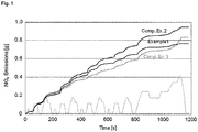
- the NEDC As opposed to the old European driving cycle (ECE-15) driving cycle, a particular feature of the NEDC is that it integrates a so-called extra-urban driving cycle, such that testing may better represent the typical usage of a car in Europe, and, accordingly, the typical emission pattern linked thereto. More specifically, in the NEDC, the old European driving cycle ECE-15 is performed in the time period of 0 to 800 seconds, after which the extra-urban driving cycle is conducted in the time period up to 1200 seconds.
- an improved catalyst may be provided.
- a catalyst comprising zeolites of both the MFI and of the CHA structure type, wherein the MFI-type zeolites contain iron and the CHA-type zeolites contain copper, display clearly improved catalytic properties, in particular when used in SCR applications.
- the present invention relates to a catalyst, preferably for use in selective catalytic reduction (SCR), said catalyst comprising
- SCR selective calatytic reduction
- reductant any catalytic process involving the reaction of nitrogen oxides NO x with a reductant.
- SCR refers to reduction reactions, wherein NO x is transformed to a reduction product thereof, which is preferably N 2 .
- reductant said term refers to any suitable reducing agent for the SCR process, wherein preferably ammonia and/or any ammonia precursor such as urea and/or ammonium carbamate is preferred, urea being preferably comprised in the ammonia precursor. Even more preferably, the term “reductant” refers to ammonia.
- reductant may, however, further include hydrocarbons and/or hydrocarbon derivatives such as oxygenated hydrocarbons, such as for example those which may be found in motor vehicle fuels and/or in motor vehicle exhaust gas, in particular in diesel fuel and/or diesel exhaust gas.
- hydrocarbons and/or hydrocarbon derivatives such as oxygenated hydrocarbons, such as for example those which may be found in motor vehicle fuels and/or in motor vehicle exhaust gas, in particular in diesel fuel and/or diesel exhaust gas.
- any conceivable zeolite of the MFI or of the CHA structure type may be used, respectively, provided that it displays the typical structural characteristics of that structure-type.
- these may for example comprise one or more zeolites selected from the group consisting of ZSM-5, FZ-1, LZ-105, Monoclinic H-ZSM-5, Mutinaite, NU-4, NU-5, TSZ, TSZ-III, TZ-01, organic-free ZSM-5, and mixtures of two or more thereof.
- the one or more zeolites of the MFI structure type include ZSM-5.
- these may comprise one or more zeolites selected from the group consisting of chabazite,
- the one or more zeolites of the CHA structure type comprise one or more zeolites selected from the group consisting of chabazite, SSZ- 13, LZ-218, Linde D, Linde R, Phi, ZK-14, and ZYT-6, and mixtures of two or more thereof, wherein more preferably, the one or more zeolites of the CHA structure type include chabazite.
- the one or more zeolites of the MFI structure type include ZSM-5 and the one or more zeolites of the CHA structure type comprise one or more zeolites selected from the group consisting of chabazite, SSZ- 13, LZ-218, Linde D, Linde R, Phi, ZK-14, and ZYT-6, and mixtures of two or more thereof, wherein even more preferably, the one or more zeolites of the MFI structure type include ZSM-5 and the one or more zeolites of the CHA structure type include chabazite.
- the one or more zeolites of the MFI structure type is ZSM-5 and the one or more zeolites of the CHA structure type is chabazite.
- At least part of the one or more MFI-type zeolites contain iron and at least part of the one or more CHA-type zeolites contain copper.
- iron contained in at least part of the one or more MFI-type zeolites and the copper contained in at least part of the one or more CHA-type zeolites said metals may respectively be contained therein in any conceivable fashion and in any conceivable state.
- iron and/or copper there is no particular limitation with respect to the oxidation state of iron and copper contained in the catalyst, nor with respect to the way in which they are contained in the respective type of zeolite.
- iron and/or copper, and more preferably both iron and copper respectively display a positive state of oxidation in the respective zeolite.
- iron and/or copper may be contained on the zeolite surface and/or within the porous structure of the respective zeolite framework.
- iron and/or copper may be included in the zeolite framework, for example by isomorphous substitution.
- the iron and/or copper, and more preferably both iron and copper are supported on the respective zeolite surface and/or within the porous structure thereof, and even more preferably both on the respective zeolite surface and within the porous structure thereof.
- both iron and copper are respectively contained in at least part of the one or more zeolites of the MFI and CHA structure type in a positive oxidation state, wherein said iron and copper is supported on the surface of the respective zeolite, including being contained within the porous structure thereof.
- the weight ratio of the one or more zeolites of the MFI structure type relative to the one or more zeolites of the CHA structure type ranges from 1 : 2 to 2 : 1, more preferably from 0.7 : 1 to 1 : 0.7, more preferably from 0.8 : 1 to 1 : 0.8, and even more preferably from 0.9 : 1 to 1 : 0.9.
- the weight ratio of the MFI-type zeolites to the CHA-type zeolites is approximately 1:1.
- the one or more zeolites of the MFI structure type and the one or more zeolites of the CHA structure type respectively comprise both Al and Si in their frameworks.
- the molar ratio of silica to alumina (SAR) in the one or more zeolites of the MFI structure type ranges from 20 to 50, more preferably from 23 to 30, and even more preferably from 25 to 27. Furthermore, the SAR in the one or more zeolites of the CHA structure type ranges from 20 to 55, more preferably from 25 to 35, and even more preferably from 28 to 32.
- the SAR in the one or more MFI-type zeolites ranges from 23 to 30, and the one or more CHA-type zeolites ranges from 25 to 35, and even more preferably that the SAR in the one or more MFI-type zeolites ranges from 25 to 27, and the one or more CHA-type zeolites ranges from 28 to 32.
- the amount of iron (Fe) in the one or more zeolites of the MFI structure type is comprised in the range of from 2.5 to 5.5 wt.-% based on the weight of said one or more zeolites of the MFI structure type, preferably the amount of Fe ranges from 3.5 to 4.2 wt.-%, and more preferably from 3.7 to 4.0 wt.-%.
- the amount of copper (Cu) in the one or more zeolites of the CHA structure type ranges from 1.0 to 4.0 wt.-% based on the weight of said one or more zeolites of the CHA structure type, preferably the amount of Cu ranges from 1.6 to 3.4 wt.-%, and more preferably from 1.8 to 3.2 wt.-%.
- the amount of iron in the one or more MFI-type zeolites ranges from 3.5 to 4.2 wt.-%, and the amount of copper in the one or more CHA-type zeolites ranges from 1.6 to 3.4 wt.-%, and even more preferably, the amount of iron in the one or more MFI-type zeolites ranges from 3.7 to 4.0 wt.-%, and the amount of copper in the one or more CHA-type zeolites ranges from 1.8 to 3.2 wt.-%.
- the catalyst may be provided in any conceivable form, such as by way of example in the form of a powder, a granulate, or a monolith.
- the catalyst further comprises a substrate, onto which the one or more zeolites are provided.
- the substrate can be made from materials commonly known in the art.
- porous materials are preferably used as the substrate material, in particular ceramic and ceramic-like materials such as cordierite, ⁇ -alumina, an aluminosilicate, cordierite-alumina, silicon carbide, aluminum titanate, silicon nitride, zirconia, mullite, zircon, zircon mullite, zircon silicate, sillimanite, a magnesium silicate, petalite, spodumene, alumina-silica-magnesia and zirconium silicate, as well as porous refractory metals and oxides thereof.
- ceramic and ceramic-like materials such as cordierite, ⁇ -alumina, an aluminosilicate, cordierite-alumina, silicon carbide, aluminum titanate, silicon nitride, zirconia, mullite, zircon, zircon mullite, zircon silicate, sillimanite, a magnesium silicate, petalite, spodumene, alumina-silica-
- refractory metal refers to one or more metals selected from the group consisting of Ti, Zr, Hf, V, Nb, Ta, Cr, Mo, W, and Re.
- the substrate may also be formed of ceramic fiber composite materials.
- the substrate is preferably formed from cordierite, silicon carbide, and/or from aluminum titanate, and even more preferably from cordierite and/or silicon carbide.
- the substrates useful for the catalysts of embodiments of the present invention may also be metallic in nature and be composed of one or more metals or metal alloys.
- the metallic substrates may be employed in various shapes such as corrugated sheet or monolithic form.
- Suitable metallic supports include the heat resistant metals and metal alloys such as titanium and stainless steel as well as other alloys in which iron is a substantial or major component.
- Such alloys may contain one or more of nickel, chromium and/or aluminum, and the total amount of these metals may advantageously comprise at least 15 wt.-% of the alloy, e.g., 10-25 wt.-% of chromium, 3-8 wt.-% of aluminum and up to 20 wt.-% of nickel.
- the alloys may also contain small or trace amounts of one or more other metals such as manganese, copper, vanadium, titanium and the like.
- the surface or the metal substrates may be oxidized at high temperatures, e.g., 1000°C and higher, to improve the resistance to corrosion of the alloys by forming an oxide layer on the surfaces the substrates.
- the substrate according to the present invention may be of any conceivable shape, provided that it allows for the fluid contact with at least a portion of the respective one or more zeolites of the MFI and CHA structure types present thereon.
- the substrate is a monolith, wherein more preferably the monolith is a flow-through monolith.
- Suitable substrates include any of those materials typically used for preparing catalysts, and will usually comprise a ceramic or metal honeycomb structure.
- the monolithic substrate contains fine, parallel gas flow passages extending from an inlet to an outlet face of the substrate, such that passages are open to fluid flow (referred to as honeycomb flow through substrates).
- the passages which are essentially straight paths from their fluid inlet to their fluid outlet, are defined by walls onto which the one or more zeolites of the MFI and CHA structure types are respectively disposed, so that the gases flowing through the passages may contact them.
- the flow passages of the monolithic substrate are thin-walled channels, which can be of any suitable cross-sectional shape and size such as trapezoidal, rectangular, square, sinusoidal, hexagonal, oval, or circular.
- Such structures may contain up to 900 gas inlet openings (i.e., cells) per square inch of cross section, wherein according to the present invention structures preferably have from 50 to 600 openings per square inch, more preferably from 300 to 500, and even more preferably from 350 to 400.
- the catalyst comprises a substrate which is a monolith, and preferably a honeycomb substrate.
- the substrate is a wall flow monolith.
- the substrate is preferably a honeycomb wall flow filter, wound or packed fiber filter, open-cell foam, or sintered metal filter, wherein wall flow filters are particularly preferred.
- useful wall flow substrates have a plurality of fine, substantially parallel gas flow passages extending along the longitudinal axis of the substrate. Typically, each passage is blocked at one end of the substrate body, with alternate passages blocked at opposite end-faces.
- Particularly preferred wall flow substrates for use in the present invention include thin porous walled honeycomb monoliths, through which a fluid stream may pass without causing too great an increase in back pressure or pressure across the catalyst.
- Ceramic wall flow substrates used in the present invention are preferably formed of a material having a porosity of at least 40%, preferably from 40 to 70%, and having a mean pore size of at least 5 microns, preferably from 5 to 30 microns. Further preferred are substrates having a porosity of at least 50% and having a mean pore size of at least 10 microns.
- the substrate preferably comprised in the catalyst is preferably selected from the group consisting of flow-through substrates and wall-flow substrates, more preferably from the group consisting of cordierite flow-through substrates and wall-flow substrates, and silicon carbide flow-through substrates and wall-flow substrates.
- the zeolites may be provided thereon in any conceivable fashion, wherein they are preferably provided thereon in the form of one or more layers which are preferably washcoat layers.
- the catalyst comprises a substrate and two or more layers provided thereon
- the zeolites may be provided in said two or more layers in any possible manner.
- the present invention includes, for example, such preferred embodiments wherein the zeolites are contained in only a single of the two or more layers, as well as embodiments wherein the zeolite is contained in more than one of the two or more layers.
- the zeolites are contained in a single layer, irrespective of the number of layers present on the substrate.
- the catalyst comprises a substrate
- the catalyst comprises one or more layers, preferably washcoat layers, provided on the substrate, the zeolites being contained in one single layer or two or more separate layers, wherein preferably the zeolites are contained in one single layer.
- the zeolites are contained in more than one of said layers
- the MFI- and CHA-type zeolites are respectively contained in each of the layers which contain zeolites, or that, alternatively, only part of the layers containing zeolites contain both MFI- and CHA-type zeolites.
- no single layer contains both MFI- and CHA-type zeolites, said zeolites being accordingly contained in separate layers of the catalyst.
- at least one of the layers in such embodiments contains both MFI- and CHA-type zeolites, wherein it is even more preferred that each of the two or more layers of said embodiments containing the zeolites also contains both the MFI- and CHA-type zeolites.
- Either the one or more zeolites of the MFI structure type, or the one or more zeolites of the CHA structure type, or both the one or more zeolites of the MFI structure type and the one or more zeolites of the CHA structure type, are respectively present in the catalyst in a loading ranging from 0.006 to 0.31 g/cm 3 (0.1 to 5.0 g/in 3 ), wherein the loading preferably ranges from 0.04 to 0.12 g/cm 3 (0.7 to 2.0 g/in 3 ), preferably from 0.061 to 0.10 g/cm 3 (1.0 to 1.7 g/in 3 ), more preferably from 0.0702 to 0.0946 g/cm 3 (1.15 to 1.55 g/in 3 ), more preferably from 0.0763 to 0.0885 g/cm (1.25 to 1.45 g/in 3 ), more preferably from 0.0806 to 0.0842 g/cm 3 (1.32 to 1.38 g/in 3 ), and even more preferably
- the respective loadings of the MFI- and CHA-type zeolites may be independent from one another, in the sense that the preferred loading ranges may apply either to the MFI- or to the CHA-type zeolites, wherein the loading of the one or more zeolites belonging to the other structure type is respectively not particularly limited.
- the present invention also comprises embodiments wherein, for example, the loading of the MFI-type zeolites ranges from 0.04 to 0.12 g/cm 3 (0.7 to 2.0 g/in 3 ), and the loading of the CHA-type zeolites ranges from 0.0806 to 0.0842 g/cm 3 (1.32 to 1.38 g/in 3 ), or embodiments wherein, for example, the loading of the MFI-type zeolites ranges from 0.061 to 0.10 g/cm 3 (1.0 to 1.7 g/in 3 ), and the loading of the CHA-type zeolites ranges from 0.0763 to 0.0885 g/cm 3 (1.25 to 1.45 g/in 3 ), or embodiments wherein, for example, the loading of the MFI-type zeolites ranges from 0.0702 to 0.0946 g/ cm 3 (1.15 to 1.55 g/in 3 ), and the loading of the CHA-type zeolites ranges from 0.0702 to 0.09
- the present invention also relates to a treatment system for an exhaust gas stream.
- the treatment system of the present invention comprises an internal combustion engine which is preferably a lean burn engine, and even more preferably a diesel engine.
- an internal combustion engine which is preferably a lean burn engine, and even more preferably a diesel engine.
- the treatment system according to the present invention comprises an exhaust gas conduit which is in fluid communication with the internal combustion engine.
- any conceivable conduit may be used, provided that it is capable of conducting exhaust gas from an internal combustion engine, and may sufficiently resist the temperatures and the chemical species encountered in the exhaust gas of an internal combustion engine, in particular of a lean burn engine such as a diesel engine.
- the fluid communication provided between the exhaust gas conduit and the internal combustion engine signifies that the treatment system allows for the constant passage of exhaust gas from the engine to the conduit.
- the catalyst is present in the exhaust gas conduit.
- the catalyst may be provided in the exhaust gas conduit in any conceivable fashion, provided that it is present within the exhaust gas conduit in the sense that it may be contacted by the exhaust gas passing through said conduit.
- the catalyst is provided in the exhaust gas conduit on a substrate as outlined in the present application, and in particular on a honeycomb substrate, which is preferably either a flow-through or a wall-flow honeycomb substrate.
- the present invention also relates to an exhaust gas treatment system comprising an internal combustion engine and an exhaust gas conduit in fluid communication with the internal combustion engine, wherein the catalyst according to the present invention is present in the exhaust gas conduit, and wherein the internal combustion engine is preferably a lean burn engine, and more preferably a diesel engine.
- the present invention also relates to embodiments wherein the inventive catalyst is comprised in an exhaust gas treatment system comprising an internal combustion engine and an exhaust gas conduit in fluid communication with the internal combustion engine, wherein said catalyst is present in the exhaust gas conduit, and wherein the internal combustion engine is preferably a lean burn engine, and more preferably a diesel engine.
- the exhaust gas treatment system further comprises a means of introducing a reductant into the exhaust gas stream, wherein said means is located upstream from the inventive MFI/CHA-zeolite catalyst.
- a means of introducing ammonia and/or urea into the exhaust gas conduit is provided.
- any means known to the skilled person may be provided, in particular those commonly applied to exhaust gas treatment systems operating with active SCR methods necessitating the direct introduction of said reductants.
- the reductant which preferably comprises ammonia and/or urea is introduced by the means of an injection nozzle provided in the exhaust gas conduit upstream from the inventive catalyst.
- the exhaust gas treatment system may suitably further comprise any further components for the effective treatment of an exhaust gas.
- said system preferably further comprises an oxidation catalyst or a catalyzed soot filter (CSF) or both an oxidation catalyst and a CSF.
- the oxidation catalyst and/or the CSF are also present within the exhaust gas conduit.
- the CSF of the present invention preferably comprises a substrate coated with a washcoat layer containing one or more catalysts for burning off trapped soot and/or oxidizing exhaust gas stream emissions.
- the soot burning catalyst can be any known catalyst for combustion of soot.
- the CSF can be coated with a one or more high surface area refractory oxides (such as e.g. alumina, silica, silica alumina, zirconia, and zirconia alumina) and/or with an oxidation catalyst (such as e.g.
- the soot burning catalyst is an oxidation catalyst comprising one or more precious metal catalysts, said one or more precious metal catalysts preferably comprising one or more metals selected from the group consisting of platinum, palladium, and rhodium.
- any oxidation catalyst may be used to this effect which is suitable for oxidizing unburned hydrocarbons, CO, and/or NO x comprised in the exhaust gas.
- oxidation catalysts are preferred which comprise one or more precious metal catalysts, and more preferably one or more precious metals selected from the group consisting of platinum, palladium, and rhodium.
- the oxidation catalyst is preferably a diesel oxidation catalyst.
- a “diesel oxidation catalyst” refers to any oxidation catalyst which is particularly well adapted to the oxidation of diesel exhaust gas, in particular with respect to the temperatures and to the composition of diesel exhaust gas encountered in the treatment thereof.
- the exhaust gas treatment system further comprises a CSF, and even more preferably both a CSF and an oxidation catalyst. Even more preferably, the exhaust gas treatment system further comprises a CSF and a diesel oxidation catalyst.
- said further components may be present in the exhaust gas conduit in any order and at any emplacement therein, provided that the effective treatment of an exhaust gas may be provided.
- the presence and/or order and/or location of said further components may depend on the type, on the state, in particular with respect to the temperature and pressure thereof, and on the average composition of the exhaust gas which is treated.
- the present invention includes preferred embodiments wherein the oxidation catalyst and/or the CSF are located upstream or downstream from the inventive MFI/CHA-zeolite catalyst, as well as preferred embodiments comprising both an oxidation catalyst and a CSF, wherein the oxidation catalyst is located upstream and the CSF downstream thereof, or wherein, vice versa, the CSF is located upstream, and the oxidation catalyst downstream thereof.
- the oxidation catalyst and/or the CSF are located upstream from the inventive MFI/CHA-zeolite catalyst, wherein even more preferably, the exhaust gas treatment system comprises both an oxidation catalyst and a CSF upstream from the inventive MFI/CHA-zeolite catalyst.
- upstream and "downstream” relates to the direction of flow of the exhaust gas through the exhaust gas conduit in fluid communication with the internal combustion engine.
- the present invention also relates to an exhaust gas treatment system as defined in the foregoing, said exhaust gas treatment system further comprising an oxidation catalyst and/or a catalyzed soot filter (CSF), wherein the oxidation catalyst and/or the CSF are preferably located upstream from the inventive MFI/CHA-zeolite catalyst, and wherein the oxidation catalyst is a diesel oxidation catalyst (DOC) in instances where the internal combustion engine is a diesel engine.
- DOC diesel oxidation catalyst
- the exhaust gas treatment system preferably further includes a means of introducing a reductant into the exhaust gas conduit, said means being located upstream from the inventive MFI/CHA-zeolite catalyst.
- said means enables the introduction of a reductant comprising ammonia and/or urea into the exhaust gas conduit.
- the present invention also relates to an exhaust gas treatment system wherein in addition to or instead of further comprising an oxidation catalyst and/or a catalyzed soot filter (CSF) respectively preferably located upstream from the inventive MFI/CHA-zeolite catalyst, the oxidation catalyst being a diesel oxidation catalyst (DOC) in instances where the internal combustion engine is a diesel engine, said system further comprises a means of introducing a reductant preferably comprising ammonia and/or urea into the exhaust gas conduit, said means being located upstream of the inventive MFI/CHA-zeolite catalyst.
- CSF catalyzed soot filter
- the exhaust gas treatment system further comprises an ammonia slip catalyst located downstream of the MFI/CHA-zeolite catalyst for oxidizing excess ammonia and/or urea which has not reacted in the SCR.
- an ammonia slip catalyst located downstream of the MFI/CHA-zeolite catalyst for oxidizing excess ammonia and/or urea which has not reacted in the SCR.
- said catalyst may be provided in the exhaust gas conduit in any manner commonly known in the art, provided that it may effectively oxidize said excess ammonia and/or urea.
- said preferred embodiments involve an exhaust gas treatment systems according to the present invention which include a means of introducing a reductant into the exhaust gas conduit as defined in the foregoing.
- the present invention further concerns a process for the treatment of a gas stream comprising NO x .
- a gas stream comprising NO x may be employed, provided that its state and composition are both suited for being treated when contacted with a MFI/CHA-zeolite catalyst according to the present invention, wherein preferably said treatment at least in part involves the selective catalytic reduction of at least part of the NO x contained in said gas.
- the gas stream used in the inventive process preferably contains at least one reductant, which is preferably ammonia and/or any ammonia precursor such as urea and/or ammonium carbamate, urea being preferably comprised in the ammonia precursor.
- the gas stream used may also contain hydrocarbons and/or hydrocarbon derivatives such as oxygenated hydrocarbons, such as for example those which may be found in motor vehicle fuels and/or in motor vehicle exhaust gas, in particular in diesel fuel and/or exhaust gas.
- Said further reductants may be contained in the gas treated in the inventive process either in addition to ammonia, or, according to further embodiments, may also be contained therein instead of ammonia.
- the gas comprises ammonia and/or urea as a reducing agent for the treatment of exhaust gas emissions, in particular via SCR.
- the present invention also relates to a process for the treatment of a gas stream comprising NO x as defined in the present application, wherein the gas stream comprises ammonia and/or urea.
- said reductant preferably comprising ammonia and/or urea
- said content of reductant in the gas stream may be reduced by SCR when contacting the MFI/CHA-zeolite catalyst of the present invention. It is however preferred, that said content does not considerably derive from the amount of reductant necessary for the maximal conversion of NO x by the catalyst.
- the maximal conversion reflects the maximum amount of NO x which may be converted by SCR at a given time point in the inventive process, i.e.
- the maximal conversion of NO x directly reflects the maximum amount of reductant, and preferably of ammonia and/or urea, which may react with NO x in the SCR process at a given time point.
- the gas stream used in the inventive process is preferably an exhaust gas stream comprising NO x .
- the process which leads to such an exhaust gas stream provided that it is suited for treatment with the MFI/CHA-zeolite catalyst according to the present invention, or may be processed to a gas stream suited for treatment with such a catalyst.
- the exhaust gas stream is an exhaust gas stream resulting from an internal combustion engine, and even more preferably from a lean burn engine.
- the exhaust gas stream is a diesel engine exhaust gas stream.
- the gas stream is contacted with the inventive MFI/CHA-zeolite catalyst for treatment thereof, wherein said contacting is achieved by either conducting the gas stream over the catalyst, or conducting the gas stream through the catalyst. Said contacting may, however, also be achieved by conducting the gas stream both over and through the inventive catalyst.
- the gas stream is either conducted over the catalyst, wherein the catalyst preferably comprises a flow-through substrate for this purpose, or the gas stream is conducted through the catalyst, wherein in this case the catalyst preferably comprises a wall-flow substrate.
- the catalyst used in the inventive process either comprises a wall-flow honeycomb substrate or a flow-through honeycomb substrate.
- the present invention also relates to a process for the treatment of a gas stream comprising NO x comprising conducting said gas stream over and/or through an MFI/CHA-zeolite catalyst according to the present invention, wherein the gas stream is preferably an exhaust gas stream, more preferably an exhaust gas stream resulting from an internal combustion engine, and even more preferably a diesel exhaust gas stream.
- the amount of NO x contained in the gas stream there is no particular limitation as to the amount of NO x contained in the gas stream, wherein preferably, the amount thereof in the gas streams used in the inventive process does not exceed 10 wt.-% based on the total weight of the exhaust gas, and more preferably does not exceed 1 wt.-%, more preferably 0.5 wt.-%, more preferably 0.1 wt-%, more preferably 0.05 wt-.%, more preferably 0.03 wt-.%, and even more preferably does not exceed 0.01 wt.-%.
- the NO 2 -content relative to the total NO x -content is 80 wt.-% or less based on 100 wt.-% of NO x , wherein more preferably, the NO 2 content is comprised in the range of from 5 to 70 wt.-%, more preferably of from 10 to 60 wt.-%, more preferably of from 15 to 55 wt.-%, and even more preferably of from 20 to 50 wt.-%.
- composition of the gas stream used in the inventive process as defined in the present application refers to the gas stream prior to its use in the inventive process, and in particular prior to the contacting thereof with the catalyst.
- said composition refers to the gas stream's composition immediately prior to contacting the catalyst, i.e. immediately before treatment thereof begins by catalyzed chemical conversion thereof.
- the present invention also relates to a process for the treatment of a gas stream comprising NO x as defined in the present application, wherein prior to the contacting of the catalyst with the gas stream, the NO 2 content thereof is 80 wt.-% or less based on 100 wt.-% of NO x , wherein preferably the NO 2 content is comprised in the range of from 5 to 70 wt.-%, more preferably of from 10 to 60 wt.-%, more preferably of from 15 to 55 wt.-%, and even more preferably of from 20 to 50 wt.-%.
- washcoat has its usual meaning in the art of a thin, adherent coating of a catalytic or other material applied to a substrate carrier material, such as a honeycomb-type carrier member, which is preferably sufficiently porous to permit the passage there through of the gas stream being treated.
- the several zeolite components of the catalyst may be applied to the substrate as mixtures of one or more components in sequential steps in a manner which will be readily apparent to those skilled in the art of catalyst manufacture.
- a typical method of manufacturing the catalyst of the present invention is to respectively provide the at least one zeolite of the MFI structure type, and the at least one further zeolite of the CHA structure type as a coating or washcoat layer on the walls of a particularly preferred flow-through or wall-flow honeycomb substrate.
- the zeolites are provided in a single washcoat on the substrate.
- the catalyst according to the present invention is however preferably prepared by further using at least one binder, wherein any conceivable binder used in the art of catalyst manufacture, and in particular in the art of automotive SCR catalyst manufacture, may be used.
- a silica-alumina binder is for example preferably used for the preparation of the inventive catalyst, wherein said binder may be provided together with one or more of the zeolite components, and is preferably provided together with the zeolite components in one or more coatings on a substrate, more preferably in one or more washcoat layers.
- the components of one or possibly more washcoat layers may respectively be processed to a slurry, preferably to an aqueous slurry.
- the substrate may then be sequentially immersed into the respective slurries for applying the individual wash-coats, after which excess slurry is removed to provide a thin coating of the two or more slurries on the walls of the substrate.
- the coated substrate is then dried and preferably calcined to provide an adherent coating of the respective component to the walls of the substrate.
- the resulting coated substrate may then be immersed into a further slurry to form a second washcoat layer deposited over the first washcoat layer.
- the substrate may then be dried and/or calcined and eventually coated with a third washcoat, which again may subsequently be dried and/or calcined to provide a finished catalyst in accordance with one embodiment of the present invention.
- any possible temperature may be used therein, provided that the process leads to the desired transformations in the catalyst without causing any notable or substantial deterioration of the catalysts stability, in particular with regard to its use in SCR.
- the temperature of calcination will not exceed 700°C, preferably 650°C, more preferably 600°C, and even more preferably will not exceed 550°C.
- calcination may for example be conducted at a temperature comprised in the range of from 500°C to 650°C, preferably 550°C to 600°C, more preferably 570°C to 590°C, more preferably , and even more preferably at a temperature comprised in the range of from 575°C to 585°C.
- the catalyst of the present invention may be prepared according to a process comprising
- a catalyst composition was prepared comprising 1.35 g/in 3 of a zeolite of the CHA structure type, said CHA-type zeolite having a silica to alumina ratio (SAR) of approximately 30 and containing 3 wt.-% of copper based on the total weight of the CHA-type zeolite, 1.35 g/in 3 of a zeolite of the MFI structure type, said MFI-type zeolite having a silica to alumina ratio of approximately 26 and containing 3.8 wt.-% of iron based on the total weight of the MFI-type zeolite, and 0.3 g/in 3 of a silica-alumina binder.
- SAR silica to alumina ratio
- a catalyst composition was prepared comprising 1.9 g/in 3 of a zeolite of the CHA structure type, said CHA-type zeolite having a silica to alumina ratio (SAR) of approximately 30 and containing 3 wt.-% of copper based on the total weight of the CHA-type zeolite, and 0.1 g/in 3 of a zirconyl binder.
- SAR silica to alumina ratio
- a catalyst composition was prepared comprising 1.35 g/in 3 of a zeolite of the BEA structure type, said BEA-type zeolite having a silica to alumina ratio (SAR) of approximately 40 and containing 1.3 wt.-% of iron based on the total weight of the BEA-type zeolite, 1.35 g/in 3 of a zeolite of the MFI structure type, said MFI-type zeolite having a silica to alumina ratio of approximately 26 and containing 3.8 wt.-% of iron based on the total weight of the MFI-type zeolite, and 0.3 g/in 3 of a silica-alumina binder.
- SAR silica to alumina ratio
- DeNO x Performance of the SCR Catalysts were evaluated in transient conditions using the New European Driving Cycle, also referred to as the MVEG (Motor Vehicle Emissions Group) cycle.
- testing conditions were such, that the NO x fraction of the exhaust gas stream contained less than 30 wt.-% of NO 2 based on the total NO x -content.
- the catalyst compositions according to Examples 1 and Comparative Examples 2 and 3 were respectively coated onto a 5.66"x5.66"x6" flow-through honeycomb substrate having a volume of 2.5 L, a cell density of 400 cells per square inch, and a wall thickness of approximately 100 ⁇ m (4 mil).
- the catalyst samples prepared in this fashion were then tested in an exhaust gas treatment system with a diesel oxidation catalyst (DOC) and a catalyzed soot filter (CSF) respectively located upstream from the tested catalyst.
- DOC diesel oxidation catalyst
- CSF catalyzed soot filter
- the inventive catalyst according to Example 1 which contains a combination of CHA- and MFI-type zeolites displays a clearly improved performance compared to the catalyst sample of Comparative Example 2 which only contains CHA-type zeolite.
- the inventive catalyst leads to a considerably higher level of conversion of the NO x emissions compared to the catalyst of Comparative Example 2.
- the inventive catalyst shows a superior conversion performance compared to Comparative Example 2 both during the period from 0 to 800s corresponding to the old European driving cycle (ECE-15), as well as during the testing period from 800 to 1200s, corresponding to the extra-urban part of the driving cycle involving higher space velocity and higher NO x mass flow.
- ECE-15 European driving cycle
- the inventive catalyst shows a somewhat poorer performance during the low temperature and moderate space velocity portion of the NEDC testing (cf. Figure 1 ). Said initial performance is, however, well compensated by an outstanding conversion rate at higher space velocities and higher NO x mass flow. Thus, as may be taken from the overall performance results displayed in Figure 2 , the inventive catalyst is also superior to a catalyst according to Comparative Example 3.
- the inventive catalyst is clearly superior over the entire cycle due to the outstanding performance in the extra-urban cycle section between 800 and 1200s. Accordingly, when considering the overall catalyst performance, the inventive catalyst is better adapted to the actual exhaust gas emission pattern of a vehicle over time, when considering the actual driving behavior of the average passenger car reflected in NEDC testing.
- the catalyst according to the present invention shows a clearly superior performance in SCR compared to a catalyst according to the prior art represent by Comparative Example 2, and, furthermore, is particularly well adapted to the actual driving conditions encountered in motor vehicle use, as reflected in NEDC testing.
- these excellent results may be attributed to the use of a specific combination of zeolite materials as defined by the catalyst of the present invention.
Landscapes
- Chemical & Material Sciences (AREA)
- Engineering & Computer Science (AREA)
- Chemical Kinetics & Catalysis (AREA)
- Materials Engineering (AREA)
- Organic Chemistry (AREA)
- Crystallography & Structural Chemistry (AREA)
- Biomedical Technology (AREA)
- Health & Medical Sciences (AREA)
- Environmental & Geological Engineering (AREA)
- Analytical Chemistry (AREA)
- General Chemical & Material Sciences (AREA)
- Oil, Petroleum & Natural Gas (AREA)
- Combustion & Propulsion (AREA)
- Catalysts (AREA)
- Exhaust Gas After Treatment (AREA)
- Exhaust Gas Treatment By Means Of Catalyst (AREA)
Claims (15)
- Catalyseur, préférablement pour une utilisation dans une réduction catalytique sélective (SCR), ledit catalyseur comprenant
une ou plusieurs zéolithe(s) de type de structure MFI et
une ou plusieurs zéolithe(s) de type de structure CHA,
au moins une partie de la ou des zéolithe(s) de type de structure MFI contenant du fer (Fe) et
au moins une partie de la ou des zéolithe(s) de type de structure CHA contenant du cuivre (Cu),
le rapport pondéral de la ou des zéolithe(s) de type de structure MFI à la ou aux zéolithe(s) de type de structure CHA se situant dans la plage de 1:2 jusqu'à 2:1,
le rapport molaire de silice à alumine (SAR) dans la ou les zéolithe(s) de type de structure MFI se situant dans la plage de 20 jusqu'à 50,
le rapport molaire de silice à alumine (SAR) dans la ou les zéolithe(s) de type de structure CHA se situant dans la plage de 20 jusqu'à 55,
la quantité de Fe dans la ou les zéolithe(s) de type de structure MFI se situant dans la plage de 2,5 jusqu'à 5,5% en poids sur la base du poids de ladite ou desdites zéolithe(s),
la quantité de Cu dans la ou les zéolithe(s) de type de structure CHA se situant dans la plage de 1,0 jusqu'à 4,0% en poids sur la base du poids de ladite ou desdites zéolithe(s) et
dans lequel soit la ou les zéolithe(s) de type de structure MFI, soit la ou les zéolithe(s) de type de structure CHA, soit à la fois la ou les zéolithe(s) de type de structure MFI et la ou les zéolithe(s) de type de structure CHA est/sont respectivement présente(s) dans le catalyseur selon une charge se situant dans la plage de 0,006 jusqu'à 0,31 g/cm3 (0,1 jusqu'à 5,0 g/in3). - Catalyseur selon la revendication 1, le rapport pondéral de la ou des zéolithe(s) de type de structure MFI à la ou aux zéolithe(s) de type de structure CHA se situant dans la plage de 0,7:1 jusqu'à 1:0,7, plus préférablement dans la plage de 0,8:1 jusqu'à 1:0,8 et encore plus préférablement dans la plage de 0,9:1 jusqu'à 1:0,9.
- Catalyseur selon la revendication 1 ou 2, le rapport molaire de silice à alumine (SAR) dans la ou les zéolithe(s) de type de structure MFI se situant dans la plage de 23 jusqu'à 30, préférablement dans la plage de 25 jusqu'à 27.
- Catalyseur selon la revendication 2 ou 3, le rapport molaire de silice à alumine (SAR) dans la ou les zéolithe(s) de type de structure CHA se situant dans la plage de 25 jusqu'à 35, préférablement dans la plage de 28 jusqu'à 32.
- Catalyseur selon l'une quelconque des revendications 1 à 4, la quantité de Fe dans la ou les zéolithe(s) de type de structure MFI se situant dans la plage de 3,5 jusqu'à 4,2% en poids sur la base du poids de ladite ou desdites zéolithe(s), préférablement dans la plage de 3,7 jusqu'à 4,0% en poids.
- Catalyseur selon l'une quelconque des revendications 1 à 5, la quantité de Cu dans la ou les zéolithe(s) de type de structure CHA se situant dans la plage de 1,6 jusqu'à 3,4% en poids sur la base du poids de ladite ou desdites zéolithe(s), préférablement dans la plage de 1,8 jusqu'à 3,2%.
- Catalyseur selon l'une quelconque des revendications 1 à 6, ledit catalyseur comprenant en outre un substrat, préférablement un substrat en nid d'abeille, sur lequel la ou les zéolithe(s) est/sont appliquée(s).
- Catalyseur selon la revendication 7, le substrat étant choisi dans le groupe constitué par les substrats à écoulement traversant et les substrats à écoulement sur paroi, préférablement dans le groupe constitué par les substrats à écoulement traversant et les substrats à écoulement sur paroi de type cordiérite et les substrats à écoulement traversant et les substrats à écoulement sur paroi de type carbure de silicium.
- Catalyseur selon la revendication 7 ou 8, le catalyseur comprenant une ou plusieurs couche(s), préférablement des couches d'imprégnation, appliquées sur le substrat, les zéolithes étant contenues dans une couche unique ou dans deux couches différentes ou plus, préférablement les zéolithes étant contenues dans une couche unique.
- Catalyseur selon l'une quelconque des revendications 1 à 9, dans lequel soit la ou les zéolithe(s) de type de structure MFI, soit la ou les zéolithe(s) de type de structure CHA, soit à la fois la ou les zéolithe(s) de type de structure MFI et la ou les zéolithe(s) de type de structure CHA est/sont respectivement présente(s) dans le catalyseur selon une charge se situant dans la plage de 0,04 jusqu'à 0,12 g/cm3 (0,7 jusqu'à 2,0 g/in3), préférablement dans la plage de 0,061 jusqu'à 0,10 g/cm3 (1,0 jusqu'à 1,7 g/in3), plus préférablement dans la plage de 0,0702 jusqu'à 0,0946 g/cm3 (1,15 jusqu'à 1,55 g/in3), plus préférablement dans la plage de 0,0763 jusqu'à 0,0885 g/cm3 (1,25 jusqu'à 1,45 g/in3), plus préférablement dans la plage de 0,0806 jusqu'à 0,0842 g/cm3 (1,32 jusqu'à 1,38 g/in3) et encore plus préférablement dans la plage de 0,0818 jusqu'à 0,083 g/cm3 (1,34 jusqu'à 1,36 g/in3).
- Système de traitement de gaz d'échappement comprenant un moteur à combustion interne et un conduit de gaz d'échappement en communication fluidique avec le moteur à combustion interne, un catalyseur selon l'une quelconque des revendications 1 à 10 étant présent dans la conduite de gaz d'échappement et
le moteur à combustion interne étant préférablement un moteur à mélange pauvre et plus préférablement un moteur diesel. - Système de traitement de gaz d'échappement selon la revendication 11, ledit système de traitement de gaz d'échappement comprenant en outre un catalyseur d'oxydation et/ou un filtre à suie catalysé (CSF), le catalyseur d'oxydation et/ou le CSF étant préférablement localisé(s) en amont du catalyseur selon l'une quelconque des revendications 1 à 10 et le catalyseur d'oxydation étant un catalyseur d'oxydation de diesel (DOC) dans les cas où le moteur à combustion interne est un moteur diesel.
- Procédé pour le traitement d'un flux gazeux comprenant des NOx, comprenant la conduite dudit flux gazeux sur et/ou à travers un catalyseur selon l'une quelconque des revendications 1 à 10, le flux gazeux étant préférablement un flux de gaz d'échappement, plus préférablement un flux de gaz d'échappement provenant d'un moteur à combustion interne et encore plus préférablement un flux de gaz d'échappement de diesel.
- Procédé pour le traitement d'un flux gazeux comprenant des NOx selon la revendication 13, le flux gazeux comprenant de l'ammoniac et/ou de l'urée.
- Procédé pour le traitement d'un flux gazeux comprenant des NOx selon la revendication 13 ou 14, dans lequel, avant la mise en contact contact du catalyseur avec le flux gazeux, sa teneur en NO2 est de 80% en poids ou moins, sur la base de 100% en poids de NOx, préférablement la teneur en NO2 étant comprise dans la plage de 5 jusqu'à 70% en poids, plus préférablement dans la plage de 10 jusqu'à 60% en poids, plus préférablement dans la plage de 15 jusqu'à 55% en poids et encore plus préférablement dans la plage de 20 jusqu'à 50% en poids.
Priority Applications (1)
| Application Number | Priority Date | Filing Date | Title |
|---|---|---|---|
| EP11765157.0A EP2555866B1 (fr) | 2010-04-08 | 2011-04-08 | Catalyseur comprenant les zéolithes Cu-CHA et Fe-MFI et procédé DE TRAITEMENT DE NOX DANS DES COURANTS GAZEUX |
Applications Claiming Priority (3)
| Application Number | Priority Date | Filing Date | Title |
|---|---|---|---|
| EP10159367 | 2010-04-08 | ||
| PCT/IB2011/051524 WO2011125049A1 (fr) | 2010-04-08 | 2011-04-08 | Catalyseur à zéolithes mixtes cu-cha/fe-mfi et procédé de traitement de nox dans des courants gazeux |
| EP11765157.0A EP2555866B1 (fr) | 2010-04-08 | 2011-04-08 | Catalyseur comprenant les zéolithes Cu-CHA et Fe-MFI et procédé DE TRAITEMENT DE NOX DANS DES COURANTS GAZEUX |
Publications (3)
| Publication Number | Publication Date |
|---|---|
| EP2555866A1 EP2555866A1 (fr) | 2013-02-13 |
| EP2555866A4 EP2555866A4 (fr) | 2014-12-10 |
| EP2555866B1 true EP2555866B1 (fr) | 2019-10-09 |
Family
ID=44762073
Family Applications (1)
| Application Number | Title | Priority Date | Filing Date |
|---|---|---|---|
| EP11765157.0A Active EP2555866B1 (fr) | 2010-04-08 | 2011-04-08 | Catalyseur comprenant les zéolithes Cu-CHA et Fe-MFI et procédé DE TRAITEMENT DE NOX DANS DES COURANTS GAZEUX |
Country Status (10)
| Country | Link |
|---|---|
| EP (1) | EP2555866B1 (fr) |
| JP (1) | JP5899199B2 (fr) |
| KR (1) | KR101844089B1 (fr) |
| CN (2) | CN104624228B (fr) |
| BR (1) | BR112012025748A2 (fr) |
| CA (1) | CA2795614C (fr) |
| MX (1) | MX360154B (fr) |
| MY (1) | MY160970A (fr) |
| WO (1) | WO2011125049A1 (fr) |
| ZA (1) | ZA201208260B (fr) |
Cited By (1)
| Publication number | Priority date | Publication date | Assignee | Title |
|---|---|---|---|---|
| WO2024044148A1 (fr) * | 2022-08-26 | 2024-02-29 | Basf Corporation | Catalyseurs de réduction catalytique sélective de zéolite cu et procédés de traitement de gaz d'échappement |
Families Citing this family (19)
| Publication number | Priority date | Publication date | Assignee | Title |
|---|---|---|---|---|
| GB2475740B (en) | 2009-11-30 | 2017-06-07 | Johnson Matthey Plc | Catalysts for treating transient NOx emissions |
| JP2014210221A (ja) * | 2013-04-17 | 2014-11-13 | 株式会社キャタラー | Scr触媒および排ガス浄化触媒システム |
| US9278343B2 (en) * | 2013-08-30 | 2016-03-08 | Johnson Matthey Public Limited Company | Zeolite blend catalysts for treating exhaust gas |
| EP3077111B1 (fr) * | 2013-12-03 | 2021-07-14 | Johnson Matthey Public Limited Company | Catalyseur rcs contenant cu et cha |
| US20150231620A1 (en) * | 2014-02-19 | 2015-08-20 | Ford Global Technologies, Llc | IRON-ZEOLITE CHABAZITE CATALYST FOR USE IN NOx REDUCTION AND METHOD OF MAKING |
| JP2015205243A (ja) * | 2014-04-21 | 2015-11-19 | 株式会社豊田中央研究所 | NOx選択還元触媒及びそれを用いたNOx浄化方法 |
| RU2018131407A (ru) | 2016-02-03 | 2020-03-03 | Басф Корпорейшн | Шабазитный катализатор, совместно обмененный на медь и железо |
| JP2019513537A (ja) * | 2016-03-08 | 2019-05-30 | ビーエーエスエフ コーポレーション | N2o排出量の低減を示すイオン交換モレキュラーシーブ触媒 |
| US20190105650A1 (en) * | 2016-04-13 | 2019-04-11 | Umicore Ag & Co. Kg | Catalyst having scr-active coating |
| EP3481549A4 (fr) * | 2016-06-08 | 2020-06-10 | BASF Corporation | MATÉRIAUX ZÉOLITIQUES ACTIVÉS PAR LE CUIVRE DE LA STRUCTURE DE CADRE CHA ISSUS D'UNE SYNTHÈSE SANS MODÈLE ORGANIQUE, ET LEUR UTILISATION EN RÉDUCTION CATALYTIQUE SÉLECTIVE DE NOx |
| WO2018088606A1 (fr) * | 2016-11-14 | 2018-05-17 | 주식회사 이엔드디 | Catalyseur scr réduisant la production d'oxyde nitreux et système scr utilisant ce catalyseur |
| KR101865389B1 (ko) * | 2016-11-15 | 2018-06-07 | 주식회사 이엔드디 | N2o 생성 억제 질소산화물 저감용 촉매 |
| CN106732763A (zh) * | 2016-11-24 | 2017-05-31 | 华南理工大学 | 一种Fe2O3/SAPO‑34低温SCR烟气脱硝催化剂及其制备方法与应用 |
| WO2019132612A1 (fr) * | 2017-12-29 | 2019-07-04 | 현대자동차주식회사 | Système d'élimination d'hydrocarbures |
| CN108722477B (zh) * | 2018-06-06 | 2021-01-15 | 中国科学院过程工程研究所 | 一种抗碱中毒高效脱硝催化剂及其制备方法和应用 |
| EP3873666A4 (fr) * | 2018-10-31 | 2022-09-07 | BASF Corporation | Couche lavis catalytique à alumine ajoutée pour réduction de nox |
| KR20220067569A (ko) * | 2020-11-16 | 2022-05-25 | 현대자동차주식회사 | 탄화수소 흡착 촉매 및 이를 포함하는 탄화수소 트랩 |
| CN113856748B (zh) * | 2021-11-04 | 2022-12-16 | 中国环境科学研究院 | 一种原子掺杂和金属团簇双修饰内表面的空心zsm-5催化剂及制备方法与应用 |
| CN114733564B (zh) * | 2022-05-10 | 2023-06-23 | 中国科学院生态环境研究中心 | 一种复合沸石scr催化剂及其制备方法与应用 |
Citations (1)
| Publication number | Priority date | Publication date | Assignee | Title |
|---|---|---|---|---|
| EP2554809A1 (fr) * | 2010-03-26 | 2013-02-06 | Cataler Corporation | Système d'épuration des gaz d'échappement |
Family Cites Families (13)
| Publication number | Priority date | Publication date | Assignee | Title |
|---|---|---|---|---|
| US5451387A (en) * | 1994-07-07 | 1995-09-19 | Mobil Oil Corporation | Selective catalytic reduction of nitrogen oxides using an iron impregnated zeolite catalyst |
| AU5449400A (en) * | 1999-05-27 | 2000-12-18 | Regents Of The University Of Michigan, The | Zeolite catalysts for selective catalytic reduction of nitric oxide by ammonia and method of making |
| DE10112444A1 (de) * | 2001-03-13 | 2002-10-02 | Krupp Uhde Gmbh | Verfahren zur Verringerung des Gehalts von N¶2¶O und NO¶x¶ in Gasen |
| US7090811B2 (en) * | 2003-12-11 | 2006-08-15 | General Motors Corporation | Method of reducing NOx in diesel engine exhaust |
| NL1026207C2 (nl) * | 2004-05-17 | 2005-11-21 | Stichting Energie | Werkwijze voor de decompositie van N2O, katalysator daarvoor en bereiding van deze katalysator. |
| US7879749B2 (en) * | 2006-08-15 | 2011-02-01 | Battelle Energy Alliance, Llc | Methods of using structures including catalytic materials disposed within porous zeolite materials to synthesize hydrocarbons |
| US7601662B2 (en) * | 2007-02-27 | 2009-10-13 | Basf Catalysts Llc | Copper CHA zeolite catalysts |
| US7645718B2 (en) * | 2007-03-26 | 2010-01-12 | Pq Corporation | Microporous crystalline material comprising a molecular sieve or zeolite having an 8-ring pore opening structure and methods of making and using same |
| US20100290963A1 (en) * | 2007-04-26 | 2010-11-18 | Johnson Matthey Public Limited Company | Transition metal / zeolite scr catalysts |
| CN101827654B (zh) * | 2007-08-13 | 2013-11-06 | Pq公司 | 含铁铝硅酸盐沸石及其制备和使用方法 |
| US20090196812A1 (en) * | 2008-01-31 | 2009-08-06 | Basf Catalysts Llc | Catalysts, Systems and Methods Utilizing Non-Zeolitic Metal-Containing Molecular Sieves Having the CHA Crystal Structure |
| WO2011061835A1 (fr) * | 2009-11-19 | 2011-05-26 | イビデン株式会社 | Structure en nid d'abeille et appareil de purification des gaz d'échappement |
| GB2475740B (en) * | 2009-11-30 | 2017-06-07 | Johnson Matthey Plc | Catalysts for treating transient NOx emissions |
-
2011
- 2011-04-08 EP EP11765157.0A patent/EP2555866B1/fr active Active
- 2011-04-08 WO PCT/IB2011/051524 patent/WO2011125049A1/fr active Application Filing
- 2011-04-08 MY MYPI2012004438A patent/MY160970A/en unknown
- 2011-04-08 JP JP2013503211A patent/JP5899199B2/ja active Active
- 2011-04-08 BR BR112012025748A patent/BR112012025748A2/pt not_active IP Right Cessation
- 2011-04-08 CA CA2795614A patent/CA2795614C/fr not_active Expired - Fee Related
- 2011-04-08 CN CN201410789506.5A patent/CN104624228B/zh active Active
- 2011-04-08 MX MX2012011539A patent/MX360154B/es active IP Right Grant
- 2011-04-08 KR KR1020127029120A patent/KR101844089B1/ko active IP Right Grant
- 2011-04-08 CN CN2011800273287A patent/CN102946998A/zh active Pending
-
2012
- 2012-11-05 ZA ZA2012/08260A patent/ZA201208260B/en unknown
Patent Citations (1)
| Publication number | Priority date | Publication date | Assignee | Title |
|---|---|---|---|---|
| EP2554809A1 (fr) * | 2010-03-26 | 2013-02-06 | Cataler Corporation | Système d'épuration des gaz d'échappement |
Cited By (1)
| Publication number | Priority date | Publication date | Assignee | Title |
|---|---|---|---|---|
| WO2024044148A1 (fr) * | 2022-08-26 | 2024-02-29 | Basf Corporation | Catalyseurs de réduction catalytique sélective de zéolite cu et procédés de traitement de gaz d'échappement |
Also Published As
| Publication number | Publication date |
|---|---|
| WO2011125049A1 (fr) | 2011-10-13 |
| EP2555866A1 (fr) | 2013-02-13 |
| CN104624228A (zh) | 2015-05-20 |
| MY160970A (en) | 2017-03-31 |
| BR112012025748A2 (pt) | 2017-08-29 |
| MX2012011539A (es) | 2012-11-16 |
| CN102946998A (zh) | 2013-02-27 |
| CN104624228B (zh) | 2018-01-26 |
| JP5899199B2 (ja) | 2016-04-06 |
| ZA201208260B (en) | 2014-01-29 |
| CA2795614C (fr) | 2018-03-06 |
| EP2555866A4 (fr) | 2014-12-10 |
| KR101844089B1 (ko) | 2018-03-30 |
| CA2795614A1 (fr) | 2011-10-13 |
| KR20130091639A (ko) | 2013-08-19 |
| MX360154B (es) | 2018-10-24 |
| JP2013527027A (ja) | 2013-06-27 |
Similar Documents
| Publication | Publication Date | Title |
|---|---|---|
| US9352307B2 (en) | Cu-CHA/Fe-MFI mixed zeolite catalyst and process for the treatment of NOx in gas streams | |
| EP2555866B1 (fr) | Catalyseur comprenant les zéolithes Cu-CHA et Fe-MFI et procédé DE TRAITEMENT DE NOX DANS DES COURANTS GAZEUX | |
| JP6348212B2 (ja) | ガス流中のNOxを処理するためのCu−CHA/Fe−BEA混合ゼオライト触媒および方法 | |
| US9999877B2 (en) | Cu-CHA/Fe-BEA mixed zeolite catalyst and process for the treatment of NOx in gas streams | |
| US11268420B2 (en) | Exhaust gas treatment system with upstream SCR catalyst | |
| EP2790813B1 (fr) | Système d'échappement pour moteur à combustion interne à mélange pauvre comprenant un catalyseur de scr | |
| JP7107937B2 (ja) | NOx吸着体触媒 | |
| KR20150128701A (ko) | 선택적 촉매 환원 촉매 시스템 | |
| US9079162B2 (en) | Fe-BEA/Fe-MFI mixed zeolite catalyst and process for the treatment of NOX in gas streams | |
| WO2018015930A1 (fr) | Catalyseur de gaz d'échappement et liants de catalyseur pour substrats de filtre | |
| EP2382031A2 (fr) | Systèmes et procédés de traitement d'émissions employant un filtre rcs catalysé et un catalyseur rcs aval | |
| JP7494123B2 (ja) | 混合ゼオライト含有scr触媒 | |
| WO2011125050A1 (fr) | Catalyseur à zéolithes mixtes fe-bea/fe-mfi et procédé de traitement de nox dans des courants gazeux à l'aide de ce catalyseur | |
| KR20230079420A (ko) | 비스무트를 함유하는 디젤 산화 촉매 | |
| US10399037B1 (en) | Nitrogen oxides storage catalyst and methods of using the same |
Legal Events
| Date | Code | Title | Description |
|---|---|---|---|
| PUAI | Public reference made under article 153(3) epc to a published international application that has entered the european phase |
Free format text: ORIGINAL CODE: 0009012 |
|
| 17P | Request for examination filed |
Effective date: 20121108 |
|
| AK | Designated contracting states |
Kind code of ref document: A1 Designated state(s): AL AT BE BG CH CY CZ DE DK EE ES FI FR GB GR HR HU IE IS IT LI LT LU LV MC MK MT NL NO PL PT RO RS SE SI SK SM TR |
|
| RIN1 | Information on inventor provided before grant (corrected) |
Inventor name: NEUBAUER, TORSTEN Inventor name: MOHANAN, JAYA L. Inventor name: DIETERLE, MARTIN Inventor name: WENDT, CLAUDIA Inventor name: STIEBELS, SUSANNE |
|
| DAX | Request for extension of the european patent (deleted) | ||
| A4 | Supplementary search report drawn up and despatched |
Effective date: 20141110 |
|
| RIC1 | Information provided on ipc code assigned before grant |
Ipc: B01J 29/80 20060101AFI20141104BHEP Ipc: B01J 37/02 20060101ALI20141104BHEP |
|
| STAA | Information on the status of an ep patent application or granted ep patent |
Free format text: STATUS: EXAMINATION IS IN PROGRESS |
|
| 17Q | First examination report despatched |
Effective date: 20161208 |
|
| GRAP | Despatch of communication of intention to grant a patent |
Free format text: ORIGINAL CODE: EPIDOSNIGR1 |
|
| STAA | Information on the status of an ep patent application or granted ep patent |
Free format text: STATUS: GRANT OF PATENT IS INTENDED |
|
| INTG | Intention to grant announced |
Effective date: 20190103 |
|
| GRAJ | Information related to disapproval of communication of intention to grant by the applicant or resumption of examination proceedings by the epo deleted |
Free format text: ORIGINAL CODE: EPIDOSDIGR1 |
|
| STAA | Information on the status of an ep patent application or granted ep patent |
Free format text: STATUS: EXAMINATION IS IN PROGRESS |
|
| INTC | Intention to grant announced (deleted) | ||
| GRAP | Despatch of communication of intention to grant a patent |
Free format text: ORIGINAL CODE: EPIDOSNIGR1 |
|
| STAA | Information on the status of an ep patent application or granted ep patent |
Free format text: STATUS: GRANT OF PATENT IS INTENDED |
|
| RIC1 | Information provided on ipc code assigned before grant |
Ipc: B01J 35/04 20060101ALI20190318BHEP Ipc: B01J 29/46 20060101ALI20190318BHEP Ipc: B01D 53/94 20060101ALI20190318BHEP Ipc: B01J 29/80 20060101AFI20190318BHEP Ipc: B01J 37/02 20060101ALI20190318BHEP Ipc: B01J 29/72 20060101ALI20190318BHEP |
|
| INTG | Intention to grant announced |
Effective date: 20190416 |
|
| GRAS | Grant fee paid |
Free format text: ORIGINAL CODE: EPIDOSNIGR3 |
|
| GRAA | (expected) grant |
Free format text: ORIGINAL CODE: 0009210 |
|
| STAA | Information on the status of an ep patent application or granted ep patent |
Free format text: STATUS: THE PATENT HAS BEEN GRANTED |
|
| AK | Designated contracting states |
Kind code of ref document: B1 Designated state(s): AL AT BE BG CH CY CZ DE DK EE ES FI FR GB GR HR HU IE IS IT LI LT LU LV MC MK MT NL NO PL PT RO RS SE SI SK SM TR |
|
| REG | Reference to a national code |
Ref country code: GB Ref legal event code: FG4D |
|
| REG | Reference to a national code |
Ref country code: CH Ref legal event code: EP |
|
| REG | Reference to a national code |
Ref country code: DE Ref legal event code: R096 Ref document number: 602011062614 Country of ref document: DE |
|
| REG | Reference to a national code |
Ref country code: IE Ref legal event code: FG4D |
|
| REG | Reference to a national code |
Ref country code: AT Ref legal event code: REF Ref document number: 1188143 Country of ref document: AT Kind code of ref document: T Effective date: 20191115 |
|
| REG | Reference to a national code |
Ref country code: NL Ref legal event code: MP Effective date: 20191009 |
|
| REG | Reference to a national code |
Ref country code: LT Ref legal event code: MG4D |
|
| REG | Reference to a national code |
Ref country code: AT Ref legal event code: MK05 Ref document number: 1188143 Country of ref document: AT Kind code of ref document: T Effective date: 20191009 |
|
| PG25 | Lapsed in a contracting state [announced via postgrant information from national office to epo] |
Ref country code: GR Free format text: LAPSE BECAUSE OF FAILURE TO SUBMIT A TRANSLATION OF THE DESCRIPTION OR TO PAY THE FEE WITHIN THE PRESCRIBED TIME-LIMIT Effective date: 20200110 Ref country code: PT Free format text: LAPSE BECAUSE OF FAILURE TO SUBMIT A TRANSLATION OF THE DESCRIPTION OR TO PAY THE FEE WITHIN THE PRESCRIBED TIME-LIMIT Effective date: 20200210 Ref country code: ES Free format text: LAPSE BECAUSE OF FAILURE TO SUBMIT A TRANSLATION OF THE DESCRIPTION OR TO PAY THE FEE WITHIN THE PRESCRIBED TIME-LIMIT Effective date: 20191009 Ref country code: NO Free format text: LAPSE BECAUSE OF FAILURE TO SUBMIT A TRANSLATION OF THE DESCRIPTION OR TO PAY THE FEE WITHIN THE PRESCRIBED TIME-LIMIT Effective date: 20200109 Ref country code: PL Free format text: LAPSE BECAUSE OF FAILURE TO SUBMIT A TRANSLATION OF THE DESCRIPTION OR TO PAY THE FEE WITHIN THE PRESCRIBED TIME-LIMIT Effective date: 20191009 Ref country code: LT Free format text: LAPSE BECAUSE OF FAILURE TO SUBMIT A TRANSLATION OF THE DESCRIPTION OR TO PAY THE FEE WITHIN THE PRESCRIBED TIME-LIMIT Effective date: 20191009 Ref country code: SE Free format text: LAPSE BECAUSE OF FAILURE TO SUBMIT A TRANSLATION OF THE DESCRIPTION OR TO PAY THE FEE WITHIN THE PRESCRIBED TIME-LIMIT Effective date: 20191009 Ref country code: LV Free format text: LAPSE BECAUSE OF FAILURE TO SUBMIT A TRANSLATION OF THE DESCRIPTION OR TO PAY THE FEE WITHIN THE PRESCRIBED TIME-LIMIT Effective date: 20191009 Ref country code: NL Free format text: LAPSE BECAUSE OF FAILURE TO SUBMIT A TRANSLATION OF THE DESCRIPTION OR TO PAY THE FEE WITHIN THE PRESCRIBED TIME-LIMIT Effective date: 20191009 Ref country code: FI Free format text: LAPSE BECAUSE OF FAILURE TO SUBMIT A TRANSLATION OF THE DESCRIPTION OR TO PAY THE FEE WITHIN THE PRESCRIBED TIME-LIMIT Effective date: 20191009 Ref country code: BG Free format text: LAPSE BECAUSE OF FAILURE TO SUBMIT A TRANSLATION OF THE DESCRIPTION OR TO PAY THE FEE WITHIN THE PRESCRIBED TIME-LIMIT Effective date: 20200109 Ref country code: AT Free format text: LAPSE BECAUSE OF FAILURE TO SUBMIT A TRANSLATION OF THE DESCRIPTION OR TO PAY THE FEE WITHIN THE PRESCRIBED TIME-LIMIT Effective date: 20191009 |
|
| PG25 | Lapsed in a contracting state [announced via postgrant information from national office to epo] |
Ref country code: IS Free format text: LAPSE BECAUSE OF FAILURE TO SUBMIT A TRANSLATION OF THE DESCRIPTION OR TO PAY THE FEE WITHIN THE PRESCRIBED TIME-LIMIT Effective date: 20200224 Ref country code: RS Free format text: LAPSE BECAUSE OF FAILURE TO SUBMIT A TRANSLATION OF THE DESCRIPTION OR TO PAY THE FEE WITHIN THE PRESCRIBED TIME-LIMIT Effective date: 20191009 Ref country code: HR Free format text: LAPSE BECAUSE OF FAILURE TO SUBMIT A TRANSLATION OF THE DESCRIPTION OR TO PAY THE FEE WITHIN THE PRESCRIBED TIME-LIMIT Effective date: 20191009 |
|
| PG25 | Lapsed in a contracting state [announced via postgrant information from national office to epo] |
Ref country code: AL Free format text: LAPSE BECAUSE OF FAILURE TO SUBMIT A TRANSLATION OF THE DESCRIPTION OR TO PAY THE FEE WITHIN THE PRESCRIBED TIME-LIMIT Effective date: 20191009 |
|
| REG | Reference to a national code |
Ref country code: DE Ref legal event code: R097 Ref document number: 602011062614 Country of ref document: DE |
|
| PG2D | Information on lapse in contracting state deleted |
Ref country code: IS |
|
| PG25 | Lapsed in a contracting state [announced via postgrant information from national office to epo] |
Ref country code: EE Free format text: LAPSE BECAUSE OF FAILURE TO SUBMIT A TRANSLATION OF THE DESCRIPTION OR TO PAY THE FEE WITHIN THE PRESCRIBED TIME-LIMIT Effective date: 20191009 Ref country code: DK Free format text: LAPSE BECAUSE OF FAILURE TO SUBMIT A TRANSLATION OF THE DESCRIPTION OR TO PAY THE FEE WITHIN THE PRESCRIBED TIME-LIMIT Effective date: 20191009 Ref country code: RO Free format text: LAPSE BECAUSE OF FAILURE TO SUBMIT A TRANSLATION OF THE DESCRIPTION OR TO PAY THE FEE WITHIN THE PRESCRIBED TIME-LIMIT Effective date: 20191009 Ref country code: CZ Free format text: LAPSE BECAUSE OF FAILURE TO SUBMIT A TRANSLATION OF THE DESCRIPTION OR TO PAY THE FEE WITHIN THE PRESCRIBED TIME-LIMIT Effective date: 20191009 Ref country code: IS Free format text: LAPSE BECAUSE OF FAILURE TO SUBMIT A TRANSLATION OF THE DESCRIPTION OR TO PAY THE FEE WITHIN THE PRESCRIBED TIME-LIMIT Effective date: 20200209 |
|
| PLBE | No opposition filed within time limit |
Free format text: ORIGINAL CODE: 0009261 |
|
| STAA | Information on the status of an ep patent application or granted ep patent |
Free format text: STATUS: NO OPPOSITION FILED WITHIN TIME LIMIT |
|
| PG25 | Lapsed in a contracting state [announced via postgrant information from national office to epo] |
Ref country code: SM Free format text: LAPSE BECAUSE OF FAILURE TO SUBMIT A TRANSLATION OF THE DESCRIPTION OR TO PAY THE FEE WITHIN THE PRESCRIBED TIME-LIMIT Effective date: 20191009 Ref country code: IT Free format text: LAPSE BECAUSE OF FAILURE TO SUBMIT A TRANSLATION OF THE DESCRIPTION OR TO PAY THE FEE WITHIN THE PRESCRIBED TIME-LIMIT Effective date: 20191009 Ref country code: SK Free format text: LAPSE BECAUSE OF FAILURE TO SUBMIT A TRANSLATION OF THE DESCRIPTION OR TO PAY THE FEE WITHIN THE PRESCRIBED TIME-LIMIT Effective date: 20191009 |
|
| 26N | No opposition filed |
Effective date: 20200710 |
|
| PG25 | Lapsed in a contracting state [announced via postgrant information from national office to epo] |
Ref country code: SI Free format text: LAPSE BECAUSE OF FAILURE TO SUBMIT A TRANSLATION OF THE DESCRIPTION OR TO PAY THE FEE WITHIN THE PRESCRIBED TIME-LIMIT Effective date: 20191009 Ref country code: MC Free format text: LAPSE BECAUSE OF FAILURE TO SUBMIT A TRANSLATION OF THE DESCRIPTION OR TO PAY THE FEE WITHIN THE PRESCRIBED TIME-LIMIT Effective date: 20191009 |
|
| REG | Reference to a national code |
Ref country code: CH Ref legal event code: PL |
|
| PG25 | Lapsed in a contracting state [announced via postgrant information from national office to epo] |
Ref country code: LI Free format text: LAPSE BECAUSE OF NON-PAYMENT OF DUE FEES Effective date: 20200430 Ref country code: CH Free format text: LAPSE BECAUSE OF NON-PAYMENT OF DUE FEES Effective date: 20200430 Ref country code: LU Free format text: LAPSE BECAUSE OF NON-PAYMENT OF DUE FEES Effective date: 20200408 |
|
| REG | Reference to a national code |
Ref country code: BE Ref legal event code: MM Effective date: 20200430 |
|
| PG25 | Lapsed in a contracting state [announced via postgrant information from national office to epo] |
Ref country code: BE Free format text: LAPSE BECAUSE OF NON-PAYMENT OF DUE FEES Effective date: 20200430 |
|
| PG25 | Lapsed in a contracting state [announced via postgrant information from national office to epo] |
Ref country code: IE Free format text: LAPSE BECAUSE OF NON-PAYMENT OF DUE FEES Effective date: 20200408 |
|
| PG25 | Lapsed in a contracting state [announced via postgrant information from national office to epo] |
Ref country code: TR Free format text: LAPSE BECAUSE OF FAILURE TO SUBMIT A TRANSLATION OF THE DESCRIPTION OR TO PAY THE FEE WITHIN THE PRESCRIBED TIME-LIMIT Effective date: 20191009 Ref country code: MT Free format text: LAPSE BECAUSE OF FAILURE TO SUBMIT A TRANSLATION OF THE DESCRIPTION OR TO PAY THE FEE WITHIN THE PRESCRIBED TIME-LIMIT Effective date: 20191009 Ref country code: CY Free format text: LAPSE BECAUSE OF FAILURE TO SUBMIT A TRANSLATION OF THE DESCRIPTION OR TO PAY THE FEE WITHIN THE PRESCRIBED TIME-LIMIT Effective date: 20191009 |
|
| PG25 | Lapsed in a contracting state [announced via postgrant information from national office to epo] |
Ref country code: MK Free format text: LAPSE BECAUSE OF FAILURE TO SUBMIT A TRANSLATION OF THE DESCRIPTION OR TO PAY THE FEE WITHIN THE PRESCRIBED TIME-LIMIT Effective date: 20191009 |
|
| P01 | Opt-out of the competence of the unified patent court (upc) registered |
Effective date: 20230314 |
|
| PGFP | Annual fee paid to national office [announced via postgrant information from national office to epo] |
Ref country code: GB Payment date: 20240321 Year of fee payment: 14 |
|
| PGFP | Annual fee paid to national office [announced via postgrant information from national office to epo] |
Ref country code: FR Payment date: 20240320 Year of fee payment: 14 |
|
| PGFP | Annual fee paid to national office [announced via postgrant information from national office to epo] |
Ref country code: DE Payment date: 20240320 Year of fee payment: 14 |