EP2555003A2 - Current transducer and load separator with same - Google Patents
Current transducer and load separator with same Download PDFInfo
- Publication number
- EP2555003A2 EP2555003A2 EP12177691A EP12177691A EP2555003A2 EP 2555003 A2 EP2555003 A2 EP 2555003A2 EP 12177691 A EP12177691 A EP 12177691A EP 12177691 A EP12177691 A EP 12177691A EP 2555003 A2 EP2555003 A2 EP 2555003A2
- Authority
- EP
- European Patent Office
- Prior art keywords
- current transformer
- current
- fuse
- transformer system
- fuse switch
- Prior art date
- Legal status (The legal status is an assumption and is not a legal conclusion. Google has not performed a legal analysis and makes no representation as to the accuracy of the status listed.)
- Granted
Links
- 238000011156 evaluation Methods 0.000 claims abstract description 11
- 230000010363 phase shift Effects 0.000 claims description 2
- 238000005259 measurement Methods 0.000 abstract description 3
- 239000004020 conductor Substances 0.000 description 8
- 238000012544 monitoring process Methods 0.000 description 3
- 230000005540 biological transmission Effects 0.000 description 1
- 238000009434 installation Methods 0.000 description 1
- 230000001960 triggered effect Effects 0.000 description 1
- 238000013024 troubleshooting Methods 0.000 description 1
Images

Classifications
-
- G—PHYSICS
- G01—MEASURING; TESTING
- G01R—MEASURING ELECTRIC VARIABLES; MEASURING MAGNETIC VARIABLES
- G01R15/00—Details of measuring arrangements of the types provided for in groups G01R17/00 - G01R29/00, G01R33/00 - G01R33/26 or G01R35/00
- G01R15/14—Adaptations providing voltage or current isolation, e.g. for high-voltage or high-current networks
- G01R15/142—Arrangements for simultaneous measurements of several parameters employing techniques covered by groups G01R15/14 - G01R15/26
Definitions
- the present invention relates to NH fuse switch disconnectors or NH fuse switch disconnectors having a housing with a bottom surface and at least one feed contact and at least one outgoing contact.
- Such high-voltage (NH) fuse-load disconnectors or NH-fuse-switch-disconnectors have long been known and serve to provide fused outgoing busbars which can be disconnected under load.
- the devices generally include one or more fuse bases disposed within the housing.
- Corresponding fuse links are, for example, mounted on a switch cover, so that when the switch cover is closed, the fuse links are inserted in the fuse bases and a connection between the respective - connectable to the busbars - feed contacts and the outgoing contacts manufactures. When opening the switch cover, the fuse links are pulled out of the fuse bases so that the connection is broken.
- the present invention can also be used in open distribution strips, in which the fuse links can be pulled out of the open housing with a suitable tool.
- the term NH fuse switch strip should therefore also include the open distribution strips.
- current transformers are usually used.
- Current transformers work like transformers, i. an alternating current flowing through the outgoing connection (primary conductor) induces, in a secondary conductor provided by the current transformer, a secondary current which is galvanically isolated from the primary circuit and which can be evaluated to measure the primary current. Thus, the measurement takes place without contact.
- plug-on current transformers which have a primary conductor (for example in the form of an electrically conductive cylindrical part) and a secondary conductor surrounding it.
- the current transformer is mounted on the feed contact so that the primary conductor contacts the feed contact and the primary conductor of the current transformer receives the current flowing through the feed contact.
- the known embodiments also allow only the display of a single parameter, such. B. the detected current.
- the display of other characteristics is either not possible or only possible as an alternative, so that a simultaneous monitoring of several parameters can not be performed.
- the current transformer system has not only the actual current transformer, but at the same time an evaluation, which determines at least one of the parameters of the group G.
- the transmitter determines at least two of the parameters from the group G and best all of the above parameters.
- the current transformer system may preferably have a bus system terminal, via which the current transformer system can be connected to a bus system, so that the determined parameters can be transmitted via this.
- the current transformer system even has a display device for displaying the determined characteristics, so that it is not necessary to connect a corresponding display.
- the current transformer is possible to arrange surrounding the outgoing contact, since the corresponding bus system and possibly a display device can be easily connected here.
- the output contact - or an element connected directly to the output contact - serves as the primary conductor for the current transformer.
- the current transformer system is either included in the housing of the fuse load disconnector or the fuse switch strip or has its own housing, in which the individual components of the current transformer system are added.
- a triggering monitoring for the at least one fuse link is provided, which is preferably also disposed in the housing.
- the trip monitoring can also be read out via the bus connection.
Landscapes
- Physics & Mathematics (AREA)
- General Physics & Mathematics (AREA)
- Transformers For Measuring Instruments (AREA)
- Fuses (AREA)
- Measurement Of Current Or Voltage (AREA)
- Measuring Instrument Details And Bridges, And Automatic Balancing Devices (AREA)
Abstract
Description
Die vorliegende Erfindung betrifft NH-Sicherungslasttrenner oder NH-Sicherungslastschaltleisten mit einem Gehäuse mit einer Bodenfläche und mindestens einem Einspeisekontakt sowie mindestens einem Abgangskontakt.The present invention relates to NH fuse switch disconnectors or NH fuse switch disconnectors having a housing with a bottom surface and at least one feed contact and at least one outgoing contact.
Solche Spannungs-Hochleistungs-(NH)-Sicherungslasttrenner oder NH-Sicherungslastschaltleisten sind seit langem bekannt und dienen dazu, abgesicherte Abgänge von Sammelschienen bereitzustellen, die unter Last getrennt werden können. Die Einrichtungen weisen im Allgemeinen ein oder mehrere Sicherungsunterteile auf, die im Gehäuse angeordnet sind. Entsprechende Sicherungseinsätze sind beispielsweise an einem Schaltdeckel montiert, sodass bei geschlossenem Schaltdeckel die Sicherungseinsätze in den Sicherungsunterteilen eingesetzt sind und eine Verbindung zwischen den jeweiligen - mit den Sammelschienen verbindbaren - Einspeisekontakten und den Abgangskontakten herstellt. Beim Öffnen des Schaltdeckels werden die Sicherungseinsätze aus den Sicherungsunterteilen gezogen, sodass die Verbindung unterbrochen ist.Such high-voltage (NH) fuse-load disconnectors or NH-fuse-switch-disconnectors have long been known and serve to provide fused outgoing busbars which can be disconnected under load. The devices generally include one or more fuse bases disposed within the housing. Corresponding fuse links are, for example, mounted on a switch cover, so that when the switch cover is closed, the fuse links are inserted in the fuse bases and a connection between the respective - connectable to the busbars - feed contacts and the outgoing contacts manufactures. When opening the switch cover, the fuse links are pulled out of the fuse bases so that the connection is broken.
Grundsätzlich kann die vorliegende Erfindung auch bei offenen Verteilerleisten eingesetzt werden, bei denen die Sicherungseinsätze mit einem geeigneten Werkzeug aus dem offenen Gehäuse gezogen werden können. Der Begriff NH-Sicherungsschaltleiste soll daher auch die offenen Verteilerleisten umfassen.In principle, the present invention can also be used in open distribution strips, in which the fuse links can be pulled out of the open housing with a suitable tool. The term NH fuse switch strip should therefore also include the open distribution strips.
Für manche Anwendungszwecke ist eine Messung des Stromflusses über den bereitgestellten Abgang erwünscht. Dazu werden meist Stromwandler eingesetzt. Stromwandler arbeiten wie Transformatoren, d.h. ein durch den Abgangsanschluss (Primärleiter) fließender Wechselstrom induziert in einem vom Stromwandler bereit gestellten Sekundärleiter einen vom Primärkreis galvanisch getrennten Sekundärstrom, der zur Messung des Primärstroms ausgewertet werden kann. Somit erfolgt die Messung berührungslos.For some applications, it is desirable to measure the current flow through the provided output. For this purpose, current transformers are usually used. Current transformers work like transformers, i. an alternating current flowing through the outgoing connection (primary conductor) induces, in a secondary conductor provided by the current transformer, a secondary current which is galvanically isolated from the primary circuit and which can be evaluated to measure the primary current. Thus, the measurement takes place without contact.
Es sind beispielsweise Aufsteck-Stromwandler bekannt, die einen Primärleiter (beispielsweise in Form eines elektrisch leitfähigen Zylinderteils) und einen diesen umgebenden Sekundärleiter aufweisen. Bei der Montage wird der Stromwandler auf dem Einspeisekontakt montiert, sodass der Primärleiter den Einspeisekontakt kontaktiert und der Primärleiter des Stromwandlers den durch den Einspeisekontakt fließenden Strom aufnimmt.For example, plug-on current transformers are known which have a primary conductor (for example in the form of an electrically conductive cylindrical part) and a secondary conductor surrounding it. During assembly, the current transformer is mounted on the feed contact so that the primary conductor contacts the feed contact and the primary conductor of the current transformer receives the current flowing through the feed contact.
Den bekannten Stromwandlersystemen ist gemeinsam, dass der Anschluss des Sekundärleiters an entsprechende Auswertungseinrichtungen mühselig ist, da jeder Stromwandler mittels zweier Anschlusskabel angeschlossen werden muss und gleichzeitig eine kurzschlusssichere Verlegung zu gewährleisten ist.The known current transformer systems have in common that the connection of the secondary conductor to appropriate evaluation facilities is cumbersome, since each current transformer must be connected by means of two connecting cables and at the same time to ensure a short-circuit safe installation.
Es ist daher für die eingangs genannten NH-Sicherungslastschaltleisten in der
In jedem Fall ist es aber notwendig, dass ein Techniker vor Ort den Stromwandler mit der Auswerte- und Anzeigevorrichtung verbindet, um festzustellen, wie viel Strom über den entsprechenden Abgang abgegriffen wird. Die bekannten Ausführungsformen erlauben auch nur die Anzeige einer einzigen Kenngröße, wie z. B. der erfassten Stromstärke. Die Anzeige von anderen Kenngrößen ist entweder nicht möglich oder nur als Alternative möglich, so dass eine gleichzeitige Überwachung von mehreren Kenngrößen nicht durchgeführt werden kann.In any case, it is necessary for a field technician to connect the current transformer to the evaluation and display device to determine how much power is being tapped from the corresponding outlet. The known embodiments also allow only the display of a single parameter, such. B. the detected current. The display of other characteristics is either not possible or only possible as an alternative, so that a simultaneous monitoring of several parameters can not be performed.
Ausgehend von dem beschriebenen Stand der Technik ist es Aufgabe der vorliegenden Erfindung, einen NH-Sicherungslasttrenner oder eine NH-Sicherungsschaltleiste der eingangs genannten Art zur Verfügung zu stellen, die eine Ermittlung der relevanten Kenngrößen auf einfache Weise erlaubt.Based on the described prior art, it is an object of the present invention to provide an NH fuse switch disconnector or a NH fuse switch strip of the type mentioned above, which allows a determination of the relevant parameters in a simple manner.
Erfindungsgemäß wird diese Aufgabe durch ein Stromwandlersystem gelöst, mit einem Stromwandler, mit dem der vom Einspeisekontakt zum Abgangskontakt fließenden Strom erfasst werden kann und diesen in eine Messspannung umwandelt, und einer Auswerteelektronik, welche auf Basis der Messspannung zumindest eine der Kenngrößen aus der Gruppe G, die besteht aus I, In, Ist, Imin, ITR, IMAX, U, Un, f, fn, PF, ermittelt, wobei I = den Stromwandler durchfließender elektrischer Strom; In = angegebene Referenzstromstärke, für die der Stromwandler ausgelegt wurde; Ist = niedrigster angegebener Wert von I, bei dem der Stromwandler bei Leistungsfaktor Eins eine elektrische Wirkenergie misst; Imin = Wert von I, oberhalb dessen die Abweichung innerhalb der Fehlergrenzen liegt; Itr = Wert von I, oberhalb dessen die Abweichung innerhalb der niedrigsten Fehlergrenzen liegt, die der für das Stromwandlersystem angegebenen Genauigkeitsklasse entsprechen; Imax = Höchstwert von I, bei dem die Abweichung innerhalb der Fehlergrenzen liegt; U = an dem Stromwandler anliegende elektrische Spannung; Un = angegebene Bezugsspannung; f = Frequenz der an den Stromwandler anliegenden Spannung; fn = angegebene Bezugsfrequenz; PF = Leistungsfaktor = cosϕ = Kosinus der Phasenverschiebung ϕ zwischen I und U.According to the invention, this object is achieved by a current transformer system, comprising a current transformer, with which the current flowing from the feed contact to the outgoing contact can be detected and converted into a measuring voltage, and evaluation electronics, which on the basis of the measuring voltage at least one of the parameters from group G, consisting of I, I n , I st , I min , I TR , I MAX , U, U n , f, f n , PF, where I = the current flowing through the current transformer; I n = specified reference current intensity for which the current transformer was designed; I st = lowest declared value of I at which the current transformer measures an active electrical energy at power factor one; I min = value of I above which the deviation is within the error limits; I tr = value of I above which the deviation is within the lowest error limits that correspond to the accuracy class specified for the CT system; I max = maximum value of I where the deviation is within the error limits; U = voltage applied to the current transformer; U n = specified reference voltage; f = frequency of the voltage applied to the current transformer; f n = specified reference frequency; PF = power factor = cosφ = cosine of the phase shift φ between I and U.
Mit anderen Worten weist das Stromwandlersystem nicht nur den eigentlichen Stromwandler auf, sondern zugleich eine Auswerteelektronik, welche zumindest einer der Kenngrößen aus der Gruppe G bestimmt.In other words, the current transformer system has not only the actual current transformer, but at the same time an evaluation, which determines at least one of the parameters of the group G.
In einer bevorzugten Ausführungsform ermittelt die Auswerteelektronik zumindest zwei der Kenngrößen aus der Gruppe G und am besten alle der genannten Kenngrößen.In a preferred embodiment, the transmitter determines at least two of the parameters from the group G and best all of the above parameters.
Das Stromwandlersystem kann vorzugsweise eine Bussystem-Anschlussklemme aufweisen, über die das Stromwandlersystem mit einem Bussystem verbindbar ist, sodass hierüber die ermittelten Kenngrößen übertragen werden können.The current transformer system may preferably have a bus system terminal, via which the current transformer system can be connected to a bus system, so that the determined parameters can be transmitted via this.
Es ist somit möglich, die Sicherungslasttrenner und Sicherungsschaltleiste mit einem Bussystem zu verbinden, sodass über einen ebenfalls mit dem Bus verbundenen Computer, der beispielsweise bei dem Energieversorger angeordnet sein kann und daher nicht unbedingt in der Nähe des Schaltschrankes sein muss, die entsprechenden Kenngrößen ausgelesen werden können. Dadurch können mehrere Kenngrößen gleichzeitig über einen längeren Zeitraum überwacht werden, ohne dass die Anwesenheit eines Technikers vonnöten ist.It is thus possible to connect the fuse load disconnector and fuse switch strip with a bus system, so that via a also connected to the bus computer, which may be located for example in the utility and therefore does not necessarily have to be in the vicinity of the cabinet, the corresponding parameters are read can. As a result, several parameters can be monitored simultaneously over a longer period without the presence of a technician is required.
Insbesondere dann, wenn mehrere Trenner oder Leisten überwacht werden sollen, ist mit Vorteil jedem NH-Sicherungslasttrenner oder jeder NH-Sicherungsschaltleiste und am besten jedem Abgangskontakt der Sicherungslasttrenner oder Sicherungsschaltleiste eine eigene Identifikationsadresse zugeordnet, sodass an einem entfernten Ort, zum Beispiel bei dem Energieversorger, die Kenngrößen für jeden einzelnen Abgangskontakt leicht erfasst werden können, ohne dass es notwendig ist, dass ein Techniker vor Ort die entsprechende Auswerteelektronik vorübergehend anschließt.In particular, if multiple disconnectors or bars to be monitored, each NH fuse switch disconnector or NH fuse switch and best each departure contact the fuse switch disconnector or fuse switch bar assigned its own identification address, so at a remote location, for example, at the power company, with advantage the characteristics for each individual outgoing contact can be easily recorded without it being necessary for a technician to temporarily connect the corresponding evaluation electronics on site.
Alternativ oder in Kombination ist es auch möglich, dass das Stromwandlersystem einen Anschluss für eine Anzeigevorrichtung aufweist. Die Anzeigevorrichtung kann dann die entsprechenden Kenngrößen auf einer Anzeige darstellen. Es versteht sich, dass der Anschluss für eine Anzeigevorrichtung nicht nur die ermittelten Kenngrößen übermitteln muss, sondern zudem die Energieversorgung für die Anzeigevorrichtung bereitstellen muss. Dadurch kann bei Bedarf auch ein Techniker vor Ort die gewünschten Kenngrößen auslesen.Alternatively or in combination, it is also possible that the current transformer system has a connection for a display device. The display device can then display the corresponding parameters on a display. It is understood that the connection for a display device not only has to transmit the determined characteristics, but also has to provide the power supply for the display device. As a result, if required, a technician can also read out the desired parameters on site.
In einer weiteren bevorzugten Ausführungsform weist das Stromwandlersystem sogar eine Anzeigevorrichtung zur Anzeige der ermittelten Kenngrößen auf, sodass es nicht notwendig ist, ein entsprechendes Display anzuschließen.In a further preferred embodiment, the current transformer system even has a display device for displaying the determined characteristics, so that it is not necessary to connect a corresponding display.
Weiterhin hat es sich gezeigt, dass der Stromwandler möglichst den Abgangskontakt umgebend anzuordnen ist, da hier das entsprechende Bussystem und gegebenenfalls eine Anzeigevorrichtung leicht angeschlossen werden können. Mit anderen Worten dient der Abgangskontakt - oder ein direkt am Abgangskontakt angeschlossenes Element - als Primärleiter für den Stromwandler.Furthermore, it has been shown that the current transformer is possible to arrange surrounding the outgoing contact, since the corresponding bus system and possibly a display device can be easily connected here. In other words, the output contact - or an element connected directly to the output contact - serves as the primary conductor for the current transformer.
Das Stromwandlersystem ist entweder in dem Gehäuse des Sicherungslasttrenners bzw. der Sicherungsschaltleiste aufgenommen oder weist ein eigenes Gehäuse auf, in dem die einzelnen Bestandteile des Stromwandlersystems aufgenommen sind.The current transformer system is either included in the housing of the fuse load disconnector or the fuse switch strip or has its own housing, in which the individual components of the current transformer system are added.
In einer bevorzugten Ausführungsform ist eine Auslöseüberwachung für den zumindest einen Sicherungseinsatz vorgesehen, die vorzugsweise ebenfalls in dem Gehäuse angeordnet wird. Die Auslöseüberwachung kann ebenfalls über den Busanschluß ausgelesen werden.In a preferred embodiment, a triggering monitoring for the at least one fuse link is provided, which is preferably also disposed in the housing. The trip monitoring can also be read out via the bus connection.
Dadurch kann nun sogar von einem entfernten Ort, zum Beispiel beim Standort des Energieversorgers, festgestellt werden, welcher Sicherungseinsatz ausgelöst hat, sodass eine Fehlersuche deutlich vereinfacht wird.As a result, even from a remote location, for example at the location of the energy supplier, it can now be determined which fuse link has triggered, so that troubleshooting is considerably simplified.
Weitere Vorteile, Merkmale und Anwendungsmöglichkeiten werden deutlich anhand der folgenden Beschreibung einer bevorzugten Ausführungsform sowie der dazugehörigen Figuren. Es zeigen:
-
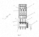
Figur 1 -
Figur 2 eine Schnittansicht eines Gehäuses eines erfindungsgemäßen Stromwandlersystems.
-
FIG. 1 a schematic representation of a NH fuse load disconnector with the current transformer system according to the invention, -
FIG. 2 a sectional view of a housing of a current transformer system according to the invention.
- 11
- N H-SicherungslasttrennerN H fuse switch disconnector
- 22
- Gehäusecasing
- 3, 3', 3"3, 3 ', 3 "
- Sicherungseinsätzefuse links
- 44
- Abgangsanschlussoutput connection
- 55
- Abgangsanschlussoutput connection
- 66
- Abgangsanschlussoutput connection
- 77
- Anzeigevorrichtungdisplay device
- 88th
- Anschlussconnection
- 99
- Gehäusecasing
- 1010
- DurchgangsöffnungThrough opening
- 1111
- Abgangsklemmeoutgoing terminal
- 1212
- Abgangsklemmeoutgoing terminal
- 1313
- Schraubescrew
- 1414
- Kammerchamber
Claims (10)
I = den Stromwandler durchfließender elektrischer Strom;
In = angegebene Referenzstromstärke, für die der Stromwandler ausgelegt wurde;
Ist = niedrigster angegebener Wert von I, bei dem der Stromwandler bei Leistungsfaktor Eins eine elektrische Wirkenergie misst;
Imin = Wert von I, oberhalb dessen die Abweichung innerhalb der Fehlergrenzen liegt;
Itr = Wert von I, oberhalb dessen die Abweichung innerhalb der niedrigsten Fehlergrenzen
liegt, die der für das Stromwandlersystem angegebenen Genauigkeitsklasse entsprechen;
Imax = Höchstwert von I, bei dem die Abweichung innerhalb der Fehlergrenzen liegt;
U = an dem Stromwandler anliegende elektrische Spannung;
Un = angegebene Bezugsspannung;
f = Frequenz der an den Stromwandler anliegenden Spannung;
fn = angegebene Bezugsfrequenz;
PF = Leistungsfaktor = cosϕ = Kosinus der Phasenverschiebung ϕ zwischen I und U.Current transformer system with a current transformer that detects a current flowing through the current transformer and converts it into a measuring voltage, and an evaluation, which based on the measuring voltage at least one of the parameters of the group G, which consists of I, I n , I st , I min , I TR , I MAX , U, U n , f, f n , PF, where
I = the electric current flowing through the current transformer;
I n = specified reference current intensity for which the current transformer was designed;
I st = lowest declared value of I at which the current transformer measures an active electrical energy at power factor one;
I min = value of I above which the deviation is within the error limits;
I tr = value of I above which the deviation is within the lowest error limits
which corresponds to the accuracy class specified for the current transformer system;
I max = maximum value of I where the deviation is within the error limits;
U = voltage applied to the current transformer;
U n = specified reference voltage;
f = frequency of the voltage applied to the current transformer;
f n = specified reference frequency;
PF = power factor = cosφ = cosine of the phase shift φ between I and U.
Priority Applications (1)
| Application Number | Priority Date | Filing Date | Title |
|---|---|---|---|
| PL12177691T PL2555003T3 (en) | 2011-08-05 | 2012-07-24 | Current transducer and load separator with same |
Applications Claiming Priority (1)
| Application Number | Priority Date | Filing Date | Title |
|---|---|---|---|
| DE102011052449A DE102011052449A1 (en) | 2011-08-05 | 2011-08-05 | Current transformer and load disconnector with such |
Publications (3)
| Publication Number | Publication Date |
|---|---|
| EP2555003A2 true EP2555003A2 (en) | 2013-02-06 |
| EP2555003A3 EP2555003A3 (en) | 2013-10-16 |
| EP2555003B1 EP2555003B1 (en) | 2017-01-04 |
Family
ID=46682666
Family Applications (1)
| Application Number | Title | Priority Date | Filing Date |
|---|---|---|---|
| EP12177691.8A Active EP2555003B1 (en) | 2011-08-05 | 2012-07-24 | Current transducer and load separator with same |
Country Status (4)
| Country | Link |
|---|---|
| EP (1) | EP2555003B1 (en) |
| DE (1) | DE102011052449A1 (en) |
| ES (1) | ES2631253T3 (en) |
| PL (1) | PL2555003T3 (en) |
Cited By (2)
| Publication number | Priority date | Publication date | Assignee | Title |
|---|---|---|---|---|
| WO2014090319A1 (en) * | 2012-12-13 | 2014-06-19 | Efen Gmbh | Current transformer and load interrupter having such a current transformer |
| EP2975707A1 (en) * | 2014-07-18 | 2016-01-20 | SAG GmbH | Built-in device, system and method for controlling voltage networks |
Families Citing this family (2)
| Publication number | Priority date | Publication date | Assignee | Title |
|---|---|---|---|---|
| DE102015105441A1 (en) | 2015-04-09 | 2016-10-13 | Efen Gmbh | Current transformer system and load disconnector with such |
| DE102017011373A1 (en) | 2017-12-11 | 2019-06-13 | Fachhochschule Südwestfalen | Measuring and control electronics for low-voltage switchgear |
Citations (7)
| Publication number | Priority date | Publication date | Assignee | Title |
|---|---|---|---|---|
| EP0696829A1 (en) | 1994-08-08 | 1996-02-14 | Jean Müller GmbH Elektrotechnische Fabrik | Electronic monitoring system for low voltage switchgear and/or installations |
| DE29705224U1 (en) | 1997-03-22 | 1997-06-26 | Jean Müller GmbH Elektrotechnische Fabrik, 65343 Eltville | Installation with an NH fuse or NH load-switching strip and a converter |
| DE19913017A1 (en) | 1999-03-23 | 2000-09-28 | Efen Elektrotech Fab | Monitoring device for measured value in electrical AC circuit in low voltage distribution unit has second voltage tapping located on live core of neighbor phase or neutral conductor for connection to measuring instrument |
| US6313727B1 (en) | 1997-07-21 | 2001-11-06 | Moeller Gmbh | Current transformer for three-phase systems |
| EP1128241B1 (en) | 2000-02-23 | 2006-10-11 | PHOENIX CONTACT GmbH & Co. Kg | Method and device for safety monitoring of a control device |
| DE102007051419A1 (en) | 2007-10-25 | 2009-04-30 | Efen Gmbh | NH fuse switch disconnector with current transformer |
| DE202010017635U1 (en) | 2009-06-04 | 2012-03-27 | Efen Gmbh | Current transformer unit |
Family Cites Families (5)
| Publication number | Priority date | Publication date | Assignee | Title |
|---|---|---|---|---|
| DE19811566A1 (en) * | 1998-03-17 | 1999-09-23 | Robert Seuffer Gmbh & Co | Potential-free electrical current measuring device e.g. for current measurement in electrical installation network |
| DE19832707C2 (en) * | 1998-07-14 | 2001-05-10 | Siemens Ag | Combined current and voltage converter for outdoor switchgear |
| DE10031964C1 (en) * | 2000-06-30 | 2002-02-21 | Moeller Gmbh | Electric power switch with integrated microprocessor control has wired interface coupled to field bus system and data input/output device coupled to current supply lines |
| DE20304461U1 (en) * | 2002-04-09 | 2003-06-12 | MBS Sulzbach Messwandler GmbH, 74429 Sulzbach-Laufen | Electronic current sensor uses microprocessor and secondary coil |
| DE102008055651A1 (en) * | 2008-10-29 | 2010-05-06 | Siemens Aktiengesellschaft | Point Diagnostic System |
-
2011
- 2011-08-05 DE DE102011052449A patent/DE102011052449A1/en not_active Withdrawn
-
2012
- 2012-07-24 EP EP12177691.8A patent/EP2555003B1/en active Active
- 2012-07-24 PL PL12177691T patent/PL2555003T3/en unknown
- 2012-07-24 ES ES12177691.8T patent/ES2631253T3/en active Active
Patent Citations (8)
| Publication number | Priority date | Publication date | Assignee | Title |
|---|---|---|---|---|
| EP0696829A1 (en) | 1994-08-08 | 1996-02-14 | Jean Müller GmbH Elektrotechnische Fabrik | Electronic monitoring system for low voltage switchgear and/or installations |
| DE29705224U1 (en) | 1997-03-22 | 1997-06-26 | Jean Müller GmbH Elektrotechnische Fabrik, 65343 Eltville | Installation with an NH fuse or NH load-switching strip and a converter |
| US6313727B1 (en) | 1997-07-21 | 2001-11-06 | Moeller Gmbh | Current transformer for three-phase systems |
| DE19913017A1 (en) | 1999-03-23 | 2000-09-28 | Efen Elektrotech Fab | Monitoring device for measured value in electrical AC circuit in low voltage distribution unit has second voltage tapping located on live core of neighbor phase or neutral conductor for connection to measuring instrument |
| EP1128241B1 (en) | 2000-02-23 | 2006-10-11 | PHOENIX CONTACT GmbH & Co. Kg | Method and device for safety monitoring of a control device |
| DE102007051419A1 (en) | 2007-10-25 | 2009-04-30 | Efen Gmbh | NH fuse switch disconnector with current transformer |
| DE202010017635U1 (en) | 2009-06-04 | 2012-03-27 | Efen Gmbh | Current transformer unit |
| EP2259284B1 (en) | 2009-06-04 | 2012-05-09 | EFEN GmbH | Electricity converter unit |
Cited By (6)
| Publication number | Priority date | Publication date | Assignee | Title |
|---|---|---|---|---|
| WO2014090319A1 (en) * | 2012-12-13 | 2014-06-19 | Efen Gmbh | Current transformer and load interrupter having such a current transformer |
| EP2975707A1 (en) * | 2014-07-18 | 2016-01-20 | SAG GmbH | Built-in device, system and method for controlling voltage networks |
| WO2016008691A1 (en) * | 2014-07-18 | 2016-01-21 | Sag Gmbh | Installation device, system and method for controlling voltage networks |
| EP2975707B1 (en) | 2014-07-18 | 2016-11-16 | SAG GmbH | Built-in device, system and method for controlling voltage networks |
| CN106537158A (en) * | 2014-07-18 | 2017-03-22 | Sag有限公司 | Installation device, system and method for controlling voltage networks |
| AU2015291317B2 (en) * | 2014-07-18 | 2018-11-22 | Sag Gmbh | Installation device, system and method for controlling voltage networks |
Also Published As
| Publication number | Publication date |
|---|---|
| ES2631253T3 (en) | 2017-08-29 |
| PL2555003T3 (en) | 2017-08-31 |
| EP2555003A3 (en) | 2013-10-16 |
| DE102011052449A1 (en) | 2013-02-07 |
| EP2555003B1 (en) | 2017-01-04 |
Similar Documents
| Publication | Publication Date | Title |
|---|---|---|
| EP2619595B1 (en) | Measurement system for monitoring at least one phase of a system | |
| EP2259284B1 (en) | Electricity converter unit | |
| EP2276137B1 (en) | Photovoltaic device | |
| EP2053627B1 (en) | NH safety circuit breaker with converter | |
| EP2546856B1 (en) | Bar for NH fuses | |
| EP2863553B1 (en) | Coupling device for coupling a powerline device and a measurement device to a power supply network, and a measurement node | |
| EP2296244A1 (en) | Method and device for connecting at least one string of a photovoltaic assembly with an inverter | |
| DE102017011374A1 (en) | Protective device for low-voltage systems with integrated measuring electronics | |
| EP2555003B1 (en) | Current transducer and load separator with same | |
| DE102013106216B4 (en) | Measuring device for current measurement | |
| EP3772796A1 (en) | Busbar holder and installation distributor | |
| DE102011075353A1 (en) | Fault monitoring system for feed point powered distribution station of electrical power supply network, has control device to determine whether error before input side, between input and output sides or behind output side is present | |
| DE102017011373A1 (en) | Measuring and control electronics for low-voltage switchgear | |
| EP3187886B1 (en) | Measuring module for a busbar system | |
| DE102010037995B4 (en) | Power supply unit and power supply system with the same | |
| WO2014090319A1 (en) | Current transformer and load interrupter having such a current transformer | |
| EP3001204A1 (en) | Bushing for at least one electrical conductor through an opening | |
| AT515818B1 (en) | Method and system for testing a substation for power transmission systems | |
| EP3385731B1 (en) | Measuring device for ground fault currents | |
| DE3623424C2 (en) | Method for switching off a single or multi-phase electrical switchgear and device for switching off | |
| DE102006002245B4 (en) | Method for monitoring a disconnectable cable in an electrical network, monitoring device and monitoring system suitable therefor | |
| DE3813403C2 (en) | Movable residual current switch | |
| DE102005022060A1 (en) | Monitoring system for e.g. generator of electrical power supply, has evaluation and monitoring electronics providing signal indicating interruption during occurrence of temperature difference at temperature sensors and change of difference | |
| DE102021111396B4 (en) | Adapter for a busbar support | |
| DE102022113758A1 (en) | Electrical protection device with measuring module |
Legal Events
| Date | Code | Title | Description |
|---|---|---|---|
| PUAI | Public reference made under article 153(3) epc to a published international application that has entered the european phase |
Free format text: ORIGINAL CODE: 0009012 |
|
| AK | Designated contracting states |
Kind code of ref document: A2 Designated state(s): AL AT BE BG CH CY CZ DE DK EE ES FI FR GB GR HR HU IE IS IT LI LT LU LV MC MK MT NL NO PL PT RO RS SE SI SK SM TR |
|
| AX | Request for extension of the european patent |
Extension state: BA ME |
|
| PUAL | Search report despatched |
Free format text: ORIGINAL CODE: 0009013 |
|
| AK | Designated contracting states |
Kind code of ref document: A3 Designated state(s): AL AT BE BG CH CY CZ DE DK EE ES FI FR GB GR HR HU IE IS IT LI LT LU LV MC MK MT NL NO PL PT RO RS SE SI SK SM TR |
|
| AX | Request for extension of the european patent |
Extension state: BA ME |
|
| RIC1 | Information provided on ipc code assigned before grant |
Ipc: H01F 38/32 20060101ALI20130911BHEP Ipc: G01R 15/18 20060101ALI20130911BHEP Ipc: H01H 85/30 20060101ALI20130911BHEP Ipc: G01R 15/14 20060101AFI20130911BHEP |
|
| 17P | Request for examination filed |
Effective date: 20140416 |
|
| RBV | Designated contracting states (corrected) |
Designated state(s): AL AT BE BG CH CY CZ DE DK EE ES FI FR GB GR HR HU IE IS IT LI LT LU LV MC MK MT NL NO PL PT RO RS SE SI SK SM TR |
|
| 17Q | First examination report despatched |
Effective date: 20141218 |
|
| TPAC | Observations filed by third parties |
Free format text: ORIGINAL CODE: EPIDOSNTIPA |
|
| GRAP | Despatch of communication of intention to grant a patent |
Free format text: ORIGINAL CODE: EPIDOSNIGR1 |
|
| INTG | Intention to grant announced |
Effective date: 20160926 |
|
| GRAS | Grant fee paid |
Free format text: ORIGINAL CODE: EPIDOSNIGR3 |
|
| GRAA | (expected) grant |
Free format text: ORIGINAL CODE: 0009210 |
|
| AK | Designated contracting states |
Kind code of ref document: B1 Designated state(s): AL AT BE BG CH CY CZ DE DK EE ES FI FR GB GR HR HU IE IS IT LI LT LU LV MC MK MT NL NO PL PT RO RS SE SI SK SM TR |
|
| REG | Reference to a national code |
Ref country code: GB Ref legal event code: FG4D Free format text: NOT ENGLISH |
|
| REG | Reference to a national code |
Ref country code: CH Ref legal event code: EP |
|
| REG | Reference to a national code |
Ref country code: AT Ref legal event code: REF Ref document number: 859759 Country of ref document: AT Kind code of ref document: T Effective date: 20170115 |
|
| REG | Reference to a national code |
Ref country code: IE Ref legal event code: FG4D Free format text: LANGUAGE OF EP DOCUMENT: GERMAN |
|
| REG | Reference to a national code |
Ref country code: DE Ref legal event code: R096 Ref document number: 502012009193 Country of ref document: DE |
|
| REG | Reference to a national code |
Ref country code: NL Ref legal event code: FP |
|
| REG | Reference to a national code |
Ref country code: SE Ref legal event code: TRGR |
|
| REG | Reference to a national code |
Ref country code: LT Ref legal event code: MG4D |
|
| REG | Reference to a national code |
Ref country code: CH Ref legal event code: NV Representative=s name: DR. GRAF AND PARTNER AG INTELLECTUAL PROPERTY, CH |
|
| PG25 | Lapsed in a contracting state [announced via postgrant information from national office to epo] |
Ref country code: IS Free format text: LAPSE BECAUSE OF FAILURE TO SUBMIT A TRANSLATION OF THE DESCRIPTION OR TO PAY THE FEE WITHIN THE PRESCRIBED TIME-LIMIT Effective date: 20170504 Ref country code: NO Free format text: LAPSE BECAUSE OF FAILURE TO SUBMIT A TRANSLATION OF THE DESCRIPTION OR TO PAY THE FEE WITHIN THE PRESCRIBED TIME-LIMIT Effective date: 20170404 Ref country code: FI Free format text: LAPSE BECAUSE OF FAILURE TO SUBMIT A TRANSLATION OF THE DESCRIPTION OR TO PAY THE FEE WITHIN THE PRESCRIBED TIME-LIMIT Effective date: 20170104 Ref country code: LT Free format text: LAPSE BECAUSE OF FAILURE TO SUBMIT A TRANSLATION OF THE DESCRIPTION OR TO PAY THE FEE WITHIN THE PRESCRIBED TIME-LIMIT Effective date: 20170104 Ref country code: HR Free format text: LAPSE BECAUSE OF FAILURE TO SUBMIT A TRANSLATION OF THE DESCRIPTION OR TO PAY THE FEE WITHIN THE PRESCRIBED TIME-LIMIT Effective date: 20170104 Ref country code: GR Free format text: LAPSE BECAUSE OF FAILURE TO SUBMIT A TRANSLATION OF THE DESCRIPTION OR TO PAY THE FEE WITHIN THE PRESCRIBED TIME-LIMIT Effective date: 20170405 |
|
| REG | Reference to a national code |
Ref country code: ES Ref legal event code: FG2A Ref document number: 2631253 Country of ref document: ES Kind code of ref document: T3 Effective date: 20170829 |
|
| PG25 | Lapsed in a contracting state [announced via postgrant information from national office to epo] |
Ref country code: BG Free format text: LAPSE BECAUSE OF FAILURE TO SUBMIT A TRANSLATION OF THE DESCRIPTION OR TO PAY THE FEE WITHIN THE PRESCRIBED TIME-LIMIT Effective date: 20170404 Ref country code: LV Free format text: LAPSE BECAUSE OF FAILURE TO SUBMIT A TRANSLATION OF THE DESCRIPTION OR TO PAY THE FEE WITHIN THE PRESCRIBED TIME-LIMIT Effective date: 20170104 Ref country code: RS Free format text: LAPSE BECAUSE OF FAILURE TO SUBMIT A TRANSLATION OF THE DESCRIPTION OR TO PAY THE FEE WITHIN THE PRESCRIBED TIME-LIMIT Effective date: 20170104 Ref country code: PT Free format text: LAPSE BECAUSE OF FAILURE TO SUBMIT A TRANSLATION OF THE DESCRIPTION OR TO PAY THE FEE WITHIN THE PRESCRIBED TIME-LIMIT Effective date: 20170504 |
|
| REG | Reference to a national code |
Ref country code: DE Ref legal event code: R097 Ref document number: 502012009193 Country of ref document: DE |
|
| PG25 | Lapsed in a contracting state [announced via postgrant information from national office to epo] |
Ref country code: CZ Free format text: LAPSE BECAUSE OF FAILURE TO SUBMIT A TRANSLATION OF THE DESCRIPTION OR TO PAY THE FEE WITHIN THE PRESCRIBED TIME-LIMIT Effective date: 20170104 Ref country code: RO Free format text: LAPSE BECAUSE OF FAILURE TO SUBMIT A TRANSLATION OF THE DESCRIPTION OR TO PAY THE FEE WITHIN THE PRESCRIBED TIME-LIMIT Effective date: 20170104 Ref country code: EE Free format text: LAPSE BECAUSE OF FAILURE TO SUBMIT A TRANSLATION OF THE DESCRIPTION OR TO PAY THE FEE WITHIN THE PRESCRIBED TIME-LIMIT Effective date: 20170104 Ref country code: IT Free format text: LAPSE BECAUSE OF FAILURE TO SUBMIT A TRANSLATION OF THE DESCRIPTION OR TO PAY THE FEE WITHIN THE PRESCRIBED TIME-LIMIT Effective date: 20170104 Ref country code: SK Free format text: LAPSE BECAUSE OF FAILURE TO SUBMIT A TRANSLATION OF THE DESCRIPTION OR TO PAY THE FEE WITHIN THE PRESCRIBED TIME-LIMIT Effective date: 20170104 |
|
| PLBE | No opposition filed within time limit |
Free format text: ORIGINAL CODE: 0009261 |
|
| STAA | Information on the status of an ep patent application or granted ep patent |
Free format text: STATUS: NO OPPOSITION FILED WITHIN TIME LIMIT |
|
| PG25 | Lapsed in a contracting state [announced via postgrant information from national office to epo] |
Ref country code: DK Free format text: LAPSE BECAUSE OF FAILURE TO SUBMIT A TRANSLATION OF THE DESCRIPTION OR TO PAY THE FEE WITHIN THE PRESCRIBED TIME-LIMIT Effective date: 20170104 Ref country code: SM Free format text: LAPSE BECAUSE OF FAILURE TO SUBMIT A TRANSLATION OF THE DESCRIPTION OR TO PAY THE FEE WITHIN THE PRESCRIBED TIME-LIMIT Effective date: 20170104 |
|
| 26N | No opposition filed |
Effective date: 20171005 |
|
| PG25 | Lapsed in a contracting state [announced via postgrant information from national office to epo] |
Ref country code: SI Free format text: LAPSE BECAUSE OF FAILURE TO SUBMIT A TRANSLATION OF THE DESCRIPTION OR TO PAY THE FEE WITHIN THE PRESCRIBED TIME-LIMIT Effective date: 20170104 |
|
| GBPC | Gb: european patent ceased through non-payment of renewal fee |
Effective date: 20170724 |
|
| REG | Reference to a national code |
Ref country code: IE Ref legal event code: MM4A |
|
| REG | Reference to a national code |
Ref country code: FR Ref legal event code: ST Effective date: 20180330 |
|
| PG25 | Lapsed in a contracting state [announced via postgrant information from national office to epo] |
Ref country code: GB Free format text: LAPSE BECAUSE OF NON-PAYMENT OF DUE FEES Effective date: 20170724 Ref country code: IE Free format text: LAPSE BECAUSE OF NON-PAYMENT OF DUE FEES Effective date: 20170724 |
|
| PG25 | Lapsed in a contracting state [announced via postgrant information from national office to epo] |
Ref country code: FR Free format text: LAPSE BECAUSE OF NON-PAYMENT OF DUE FEES Effective date: 20170731 |
|
| REG | Reference to a national code |
Ref country code: BE Ref legal event code: MM Effective date: 20170731 |
|
| PG25 | Lapsed in a contracting state [announced via postgrant information from national office to epo] |
Ref country code: LU Free format text: LAPSE BECAUSE OF NON-PAYMENT OF DUE FEES Effective date: 20170724 |
|
| PG25 | Lapsed in a contracting state [announced via postgrant information from national office to epo] |
Ref country code: BE Free format text: LAPSE BECAUSE OF NON-PAYMENT OF DUE FEES Effective date: 20170731 |
|
| PG25 | Lapsed in a contracting state [announced via postgrant information from national office to epo] |
Ref country code: MT Free format text: LAPSE BECAUSE OF FAILURE TO SUBMIT A TRANSLATION OF THE DESCRIPTION OR TO PAY THE FEE WITHIN THE PRESCRIBED TIME-LIMIT Effective date: 20170104 |
|
| PG25 | Lapsed in a contracting state [announced via postgrant information from national office to epo] |
Ref country code: HU Free format text: LAPSE BECAUSE OF FAILURE TO SUBMIT A TRANSLATION OF THE DESCRIPTION OR TO PAY THE FEE WITHIN THE PRESCRIBED TIME-LIMIT; INVALID AB INITIO Effective date: 20120724 Ref country code: MC Free format text: LAPSE BECAUSE OF FAILURE TO SUBMIT A TRANSLATION OF THE DESCRIPTION OR TO PAY THE FEE WITHIN THE PRESCRIBED TIME-LIMIT Effective date: 20170104 |
|
| PG25 | Lapsed in a contracting state [announced via postgrant information from national office to epo] |
Ref country code: CY Free format text: LAPSE BECAUSE OF NON-PAYMENT OF DUE FEES Effective date: 20170104 |
|
| PG25 | Lapsed in a contracting state [announced via postgrant information from national office to epo] |
Ref country code: MK Free format text: LAPSE BECAUSE OF FAILURE TO SUBMIT A TRANSLATION OF THE DESCRIPTION OR TO PAY THE FEE WITHIN THE PRESCRIBED TIME-LIMIT Effective date: 20170104 |
|
| PG25 | Lapsed in a contracting state [announced via postgrant information from national office to epo] |
Ref country code: TR Free format text: LAPSE BECAUSE OF FAILURE TO SUBMIT A TRANSLATION OF THE DESCRIPTION OR TO PAY THE FEE WITHIN THE PRESCRIBED TIME-LIMIT Effective date: 20170104 |
|
| PG25 | Lapsed in a contracting state [announced via postgrant information from national office to epo] |
Ref country code: AL Free format text: LAPSE BECAUSE OF FAILURE TO SUBMIT A TRANSLATION OF THE DESCRIPTION OR TO PAY THE FEE WITHIN THE PRESCRIBED TIME-LIMIT Effective date: 20170104 |
|
| PGFP | Annual fee paid to national office [announced via postgrant information from national office to epo] |
Ref country code: ES Payment date: 20230804 Year of fee payment: 12 Ref country code: CH Payment date: 20230802 Year of fee payment: 12 Ref country code: AT Payment date: 20230705 Year of fee payment: 12 |
|
| PGFP | Annual fee paid to national office [announced via postgrant information from national office to epo] |
Ref country code: SE Payment date: 20230727 Year of fee payment: 12 Ref country code: PL Payment date: 20230706 Year of fee payment: 12 Ref country code: DE Payment date: 20230727 Year of fee payment: 12 |
|
| PGFP | Annual fee paid to national office [announced via postgrant information from national office to epo] |
Ref country code: NL Payment date: 20240726 Year of fee payment: 13 |