EP2553552B1 - Touch screen interface for laser processing - Google Patents
Touch screen interface for laser processing Download PDFInfo
- Publication number
- EP2553552B1 EP2553552B1 EP11763449.3A EP11763449A EP2553552B1 EP 2553552 B1 EP2553552 B1 EP 2553552B1 EP 11763449 A EP11763449 A EP 11763449A EP 2553552 B1 EP2553552 B1 EP 2553552B1
- Authority
- EP
- European Patent Office
- Prior art keywords
- specimen
- controller
- view
- commands
- touch screen
- Prior art date
- Legal status (The legal status is an assumption and is not a legal conclusion. Google has not performed a legal analysis and makes no representation as to the accuracy of the status listed.)
- Active
Links
- 230000033001 locomotion Effects 0.000 claims description 68
- 230000003287 optical effect Effects 0.000 claims description 25
- 230000008859 change Effects 0.000 claims description 6
- 238000000034 method Methods 0.000 claims description 6
- 230000004044 response Effects 0.000 claims description 6
- 238000003384 imaging method Methods 0.000 claims description 5
- 238000000095 laser ablation inductively coupled plasma mass spectrometry Methods 0.000 claims description 5
- 238000004611 spectroscopical analysis Methods 0.000 claims description 5
- 238000004993 emission spectroscopy Methods 0.000 claims description 4
- 238000009616 inductively coupled plasma Methods 0.000 claims description 4
- 238000000608 laser ablation Methods 0.000 claims description 4
- 238000001840 matrix-assisted laser desorption--ionisation time-of-flight mass spectrometry Methods 0.000 claims description 4
- 230000001131 transforming effect Effects 0.000 claims 2
- 239000000463 material Substances 0.000 description 7
- 238000010586 diagram Methods 0.000 description 6
- 238000000386 microscopy Methods 0.000 description 3
- XKRFYHLGVUSROY-UHFFFAOYSA-N Argon Chemical compound [Ar] XKRFYHLGVUSROY-UHFFFAOYSA-N 0.000 description 2
- IJGRMHOSHXDMSA-UHFFFAOYSA-N Atomic nitrogen Chemical compound N#N IJGRMHOSHXDMSA-UHFFFAOYSA-N 0.000 description 2
- 230000008901 benefit Effects 0.000 description 2
- 230000000694 effects Effects 0.000 description 2
- 230000006872 improvement Effects 0.000 description 2
- 238000002354 inductively-coupled plasma atomic emission spectroscopy Methods 0.000 description 2
- 238000000399 optical microscopy Methods 0.000 description 2
- 229920000742 Cotton Polymers 0.000 description 1
- 229910052786 argon Inorganic materials 0.000 description 1
- 230000005540 biological transmission Effects 0.000 description 1
- 238000004891 communication Methods 0.000 description 1
- 230000003247 decreasing effect Effects 0.000 description 1
- 238000005516 engineering process Methods 0.000 description 1
- 239000011261 inert gas Substances 0.000 description 1
- 230000004048 modification Effects 0.000 description 1
- 238000012986 modification Methods 0.000 description 1
- 229910052757 nitrogen Inorganic materials 0.000 description 1
- 230000008569 process Effects 0.000 description 1
- 102000004169 proteins and genes Human genes 0.000 description 1
- 108090000623 proteins and genes Proteins 0.000 description 1
- 238000006467 substitution reaction Methods 0.000 description 1
- 230000007704 transition Effects 0.000 description 1
Images


Classifications
-
- B—PERFORMING OPERATIONS; TRANSPORTING
- B23—MACHINE TOOLS; METAL-WORKING NOT OTHERWISE PROVIDED FOR
- B23K—SOLDERING OR UNSOLDERING; WELDING; CLADDING OR PLATING BY SOLDERING OR WELDING; CUTTING BY APPLYING HEAT LOCALLY, e.g. FLAME CUTTING; WORKING BY LASER BEAM
- B23K26/00—Working by laser beam, e.g. welding, cutting or boring
- B23K26/02—Positioning or observing the workpiece, e.g. with respect to the point of impact; Aligning, aiming or focusing the laser beam
- B23K26/03—Observing, e.g. monitoring, the workpiece
- B23K26/032—Observing, e.g. monitoring, the workpiece using optical means
-
- B—PERFORMING OPERATIONS; TRANSPORTING
- B23—MACHINE TOOLS; METAL-WORKING NOT OTHERWISE PROVIDED FOR
- B23K—SOLDERING OR UNSOLDERING; WELDING; CLADDING OR PLATING BY SOLDERING OR WELDING; CUTTING BY APPLYING HEAT LOCALLY, e.g. FLAME CUTTING; WORKING BY LASER BEAM
- B23K26/00—Working by laser beam, e.g. welding, cutting or boring
- B23K26/08—Devices involving relative movement between laser beam and workpiece
- B23K26/083—Devices involving movement of the workpiece in at least one axial direction
- B23K26/0853—Devices involving movement of the workpiece in at least in two axial directions, e.g. in a plane
-
- G—PHYSICS
- G02—OPTICS
- G02B—OPTICAL ELEMENTS, SYSTEMS OR APPARATUS
- G02B21/00—Microscopes
- G02B21/24—Base structure
- G02B21/26—Stages; Adjusting means therefor
Definitions
- This invention is a touch screen user interface for imaging devices.
- a touch screen interface for microscopy systems wherein the microscope has motion stages for holding the specimen to be examined and where the touch screen user interface is connected to a controller which receives commands from the touch screen user interface and converts them into commands which drive the motion stages.
- a touch screen user interface for optical microscopy wherein the user can enter commands to the system via touch screen user interface and have the motion stages respond to those commands as if the user had moved the specimen directly rather than touching an image of the specimen on a touch screen.
- optical microscopy is broad, encompassing many types of optical and other devices which rely upon magnification to image or examine or extract information regarding specimens that are smaller than are normally visible with the un-aided human eye.
- computer-assisted microscopes wherein a computer is attached to the microscope to provide a display of the image data being produced by the microscope and a user interface to control the various capabilities of the microscope.
- such devices as electron microscopes or confocal microscopes also have computers for image acquisition, display, management and user interface functions.
- optical microscopes used in laser processing systems where the microscope is used to align and plan the laser beam path with respect to the specimen and optionally inspect the results of laser processing.
- Exemplary laser processing systems that use optical microscopes in this fashion include laser ablation inductively coupled plasma mass spectroscopy (LA ICP-MS), )laser ablation inductively coupled plasma emission spectroscopy (ICP-OES/ICP-AES) and matrix assisted laser desorption ionization time of flight (MALDI-TOF) spectroscopy.
- LA ICP-MS laser ablation inductively coupled plasma mass spectroscopy
- ICP-OES/ICP-AES laser ablation inductively coupled plasma emission spectroscopy
- MALDI-TOF matrix assisted laser desorption ionization time of flight
- a problem that computer assisted microscopy systems have in common is that the user needs to select the point on the specimen at which the laser impinges. This is to control the composition and quality of the sample of the specimen created by the laser. Often the specimen is sealed in a sample chamber with limited access. This means that the field of view must often be moved around relative to the specimen under examination using remote controls. Added to this is the 3-dimensional nature of some specimens and the limited depth of field of typical microscope systems at high magnifications which combine to require that the field of view be moved in three dimensions including possibly three degrees of rotation in order to image a specimen as desired.
- a problem is that the controls to change the field of view in this fashion may be divided between two or more motion elements and coordinating these motions to provide a desired transition of the relationship between field of view and specimen can be a difficult task.
- altering the relation between the laser beam and the specimen is a common task in these types of systems. Any improvement in user interface that decreased setup time and made positioning specimens easier and faster would be of positive benefit.
- Touch screen technology is well-known and widely commercially available. It involves adding equipment to a display to allow the user to input commands to the system by touching a display screen.
- Touch screen displays typically work either by detecting changes in capacitance caused by the user's touch or by detecting changes in infrared transmission across the screen.
- the screen transmits the coordinates of the point on the screen touched to a controller.
- the controller typically interprets the coordinates of the screen touch as being from a pointing device such as a mouse or trackball and takes appropriate actions depending upon how it has been programmed.
- a touch screen user interface for computer-assisted microscopy systems that is operatively connected to motion stages to permit the user to input commands to the motion stages to alter the field of view of the system and improve system setup, increase throughput and overcome the problems associated with achieving desired changes in the relationship between the specimen and the laser beam.
- This invention is a touch screen interface integrated with an optical microscope in a laser processing system.
- aspects of this invention include an optical system having a controller, a field of view and a specimen to be viewed, and includes a touch screen user interface operatively connected to the controller.
- Other aspects of this invention include motion stages operatively connected to the controller which hold the specimen and change the relationship between said specimen and said field of view.
- the controller is operative to input user commands from a touch screen user interface, transform the user commands into output commands and output the output commands to the motion stages.
- the motion stages in response to said output commands, alter the relationship between said field of view and the specimen according to input user commands from a touch screen.
- the controller is operative to detect the motion of the user's touch input commands on the touch screen user interface and then to direct the motion stages to move the specimen with respect to the field of view of the camera, thereby changing the image being displayed on the touch screen user interface as if the user were directly manipulating the specimen
- Exemplary laser processing systems that could benefit from this invention include laser ablation inductively coupled plasma mass spectroscopy, laser ablation inductively coupled plasma emission spectroscopy and matrix assisted laser desorption ionization time of flight spectroscopy.
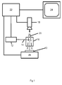
- a schematic diagram of an embodiment of this invention is shown in Fig 1 .
- These systems can all employ optical microscopes to view the specimen to be processed. In operation a specimen is placed in the system and the optical microscope is used to select a start position for the laser beam to impinge upon the specimen and begin processing. This is accomplished by acquiring images of a field of view of the specimen and displaying it on a touch screen monitor. This display is "live" and continuous, meaning that any changes in the field of view of the camera will be displayed on the touch screen monitor.
- a graphic overlay indicates the position at which the laser beam will initially impinge upon the specimen.
- the monitor may also display a graphic overlay showing the tool path along which the laser beam will be subsequently directed to impinge the specimen.
- the user touches the screen and drags a finger across the screen.
- the controller detects the motion of the user's finger on the screen and then directs the motion stages to move the specimen with respect to the field of view of the camera in order to make the image of the specimen on the touch screen appear as if the user had moved the image itself, rather than repositioning the sample in the field of view.
- Figs 2a and 2b illustrate how the invention is used to select a new start point for laser processing.
- the user desires to change the start point for laser processing in Fig 2a
- the user begins by touching the screen anywhere on the image of the specimen.
- the touch screen interface detects the movement of the user's finger on the screen and directs the motion stages to physically move the specimen under the field of view of the optical microscope, thereby changing the image being viewed on the monitor.
- touching the screen and dragging a finger across the screen will make the image data on the screen appear as if it were being dragged by the finger.
- the controller is directing the motion stages to move the specimen in the field of view of the camera to simulate the motion that would occur if the user had moved the specimen by hand rather than dragging a finger across a touch screen.
- Fig 2b shows the touch screen following user input showing the movement of the image data in relation to the onscreen graphic overlay showing the laser beam impact point.
- the controller can be programmed to offer many different options for responding to user touch screen input.
- the controller can move the motion stages to cause the image data to move either more or less than the motion input from the screen. This would have the effect of either accelerating specimen motion or making it more sensitive to small motion for fine adjustments.
- the controller can also interpret some motions relating to Z-axis motion, where moving a finger up and down on the screen, for example, would move the specimen up and down in the field of view, potentially moving the specimen in and out of focus. Other motions can be programmed to move the specimen in 3D, if desired.
- the controller can be programmed to move the cursor or other screen graphics in response to user touch screen input.
- the user could move the point where the laser beam will impinge upon the specimen by touching the screen and moving the graphic device which indicates the location of the laser beam.
- the controller then directs the motion stages to move the specimen in relation to the laser beam in order to have it impinge at the selected position.
- Adding a touch screen interface, controller and motion stages to an optical microscope equipped laser processing system allows the user to interact with a touch screen and have it appear as if they were directly manipulating a specimen. This is significant for two reasons. The first is that the specimen may be sealed in a specific environment for processing. Laser processing systems sometimes require the specimen to be sealed in an inert gas atmosphere, such as nitrogen or argon, to allow processing, making the specimen difficult to manipulate directly. In addition, in cases where complex motion stages are used to move the part, motion of two or more actuator/stage/encoder units may have to be coordinated to effect a desired change in position. Adding an appropriately programmed touch screen interface reduces all of these motions to a simple screen touch. Providing a laser processing system with the improvements described herein will make the system easier to operate and increase system throughput.
- This invention is a touch screen interface integrated with an optical microscope in a laser processing system.
- An embodiment of this invention is shown in Fig 1 .
- This embodiment includes a specimen 10, and a laser 12 having a laser beam 14.
- the laser beam 14 is directed to the specimen 10 by an optical microscope 16.
- This optical microscope 16 is an exemplary optical device which combines the optical axes of the laser 10 and the camera field of view 20 to permit the camera 18 to image the portion of specimen 10 that falls within the field of view 20.
- Other optical devices can also be used to combine the laser beam 14 and camera field of view 20, for example a half-silvered mirror (not shown).
- the system can be constructed so that the camera field of view 20 and the laser beam 14 are not on the same optical axis and therefore require separate optical devices (not shown) to direct the laser beam 14 and camera field of view 20.
- the controller 22 calculates the actual offset between the camera field of view 20 and the laser beam 14 and applies this offset to subsequent calculations.
- the camera 18 is connected to a controller 22 which directs the camera to acquire image data and transmit it to the controller 22.
- the controller 22 displays the image data from the camera 18 on the touch screen monitor 24.
- the camera 18 is typically a video type camera which is capable of acquiring image data continuously or at frame rates high enough to appear continuous.
- the controller 22 is also connected to motion stages 26 which move the specimen 10 in relation to the laser beam 14 and the camera field of view 20. Although this embodiment shows the specimen 10 being carried by the motion stages 26, the system could also move the laser beam 14 and the field of view 20 in relation to the specimen 10, or split the motion between these elements by attaching motion stages to each (not shown).
- Embodiments of this invention can alter the position of the specimen 10 with relation to the laser beam 14 and field of view 20 in up to three dimensions (X, Y and Z) and three rotations (rho, phi and theta) about three axes to permit the system to apply the laser beam 14 to any desired portion of the specimen 10.
- the laser beam 14 is used to ablate material from the specimen 10 to permit examination of the ablated material. It is typically the case that the user desires to select a particular portion or portions of the specimen 10 to ablate for examination.
- the specimen 10 may be composed of more than one type of material and the user desires to study only one of the materials. The user would use the image of the specimen 10 falling within the field of view 20 displayed on the touch screen 24 to position the laser beam 14 on the specimen 10 by touching the touch screen 24 and thereby directing the controller 22 to command the motion stages 26 to move the specimen 10 with respect to the laser beam 14 and field of view 20. This process is illustrated in Figs 2a and 2b.
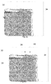
- Fig 2a shows an embodiment of this invention with a touch screen display 30 displaying an image of a specimen 32.
- On the touch screen display 30 overlaid on the image of the specimen 32 are overlay graphics indicating the point 34 at which the laser beam 14 will impinge upon the specimen when the laser is directed to emit a laser beam.
- Fig 2b shows how the user can alter the point 34 at which the laser beam will impinge upon the specimen 10.
- the user touches the screen at 38 and drags the finger across the screen to 40 along the path indicated by the arrow. This causes the controller 22 to direct the motion stages 26 to move the specimen 10 within the field of view 20, causing the image of the specimen 32 to change on the touch screen display 30, thereby moving the point 34 at which the laser will impinge the specimen 10.
- this motion can be programmed to either translate the motion of the user's finger on the screen 38, 40 into exactly matching the motion of the relation between the specimen 10 and the camera field of view 20, thereby allowing the user to alter the relationship between the specimen 10 and the camera field of view 20 and hence the location of the displayed image of the specimen 32 on the touch screen display 30 in a one-to-one correspondence to the motion of the user's finger on the screen 38, 40.
- the system is programmed to either magnify or minify the user's input finger motion on the screen 38, 40.
- the relationship between the specimen 10 and the field of view 20 can be programmed to make the image of the specimen 32 on the touch screen display 30 move more or less than the user's input finger motion 38, 40, thereby either exaggerating the input motion to speed movement over a larger specimen area or reducing the input motion to improve precision.
- Directing the motion stages 26 in response to user input from the touch screen 30 in this fashion requires that the controller 22 transform the input user commands such as generated by dragging a finger from point 38 to point 40 from screen coordinates to output commands for the motion stages. This may involve splitting the motion between multiple axes of the motion stages. For example, if the specimen 10 is held on a pair of X, Y stages, a diagonal movement input on the screen 30 would have to be transformed by the controller 22 into output commands to both the X and Y axes of the motion stages 26 to cause a diagonal movement of the specimen 10 that corresponds to the diagonal user command input on the touch screen 30. Another example would be if the specimen had three dimensional surface detail.
- Fig 3 shows further embodiment of the instant invention, wherein a touch screen display 41, displays an image of a specimen 42.
- exemplary tool paths 44, 46, 48 are shown which indicate multiple locations where the laser will be directed to ablate material from the specimen. Shown are a raster pattern 44, a collection of points 46 and an arbitrary path 48.
- These exemplary tool paths 44, 46, 48 are designed by the user and associated with the image of the specimen using graphics input software (not shown).
- FIG 4 Another embodiment of this invention is shown in Fig 4 .
- This embodiment has a second camera 50 with a large field of view 52 which is displayed on a second monitor having a touch screen 54.
- This touch screen monitor 54 is in communication with the controller 22 to input commands that are transformed and result in movement of the motion stage 26.
- the high resolution camera 18 continues to view a high resolution view of the specimen 10 through the microscope 16.
- the large field of view camera 50 and touch screen monitor 54 can be used to move the specimen with relation to the laser processing system while the small field of view (high resolution) camera 18 and monitor 24 is used to view the specimen.
- the system may have one or two touch screen interfaces or combine the displays on one monitor.
Landscapes
- Engineering & Computer Science (AREA)
- Physics & Mathematics (AREA)
- Optics & Photonics (AREA)
- Plasma & Fusion (AREA)
- Mechanical Engineering (AREA)
- Microscoopes, Condenser (AREA)
- General Physics & Mathematics (AREA)
- General Engineering & Computer Science (AREA)
- Theoretical Computer Science (AREA)
- Chemical & Material Sciences (AREA)
- Human Computer Interaction (AREA)
- Analytical Chemistry (AREA)
- Position Input By Displaying (AREA)
- User Interface Of Digital Computer (AREA)
Applications Claiming Priority (2)
| Application Number | Priority Date | Filing Date | Title |
|---|---|---|---|
| US12/752,800 US9492887B2 (en) | 2010-04-01 | 2010-04-01 | Touch screen interface for laser processing |
| PCT/US2011/030761 WO2011123667A2 (en) | 2010-04-01 | 2011-03-31 | Touch screen interface for laser processing |
Publications (3)
| Publication Number | Publication Date |
|---|---|
| EP2553552A2 EP2553552A2 (en) | 2013-02-06 |
| EP2553552A4 EP2553552A4 (en) | 2013-11-20 |
| EP2553552B1 true EP2553552B1 (en) | 2016-11-16 |
Family
ID=44709218
Family Applications (1)
| Application Number | Title | Priority Date | Filing Date |
|---|---|---|---|
| EP11763449.3A Active EP2553552B1 (en) | 2010-04-01 | 2011-03-31 | Touch screen interface for laser processing |
Country Status (7)
| Country | Link |
|---|---|
| US (1) | US9492887B2 (ja) |
| EP (1) | EP2553552B1 (ja) |
| JP (1) | JP5815018B2 (ja) |
| KR (1) | KR101887887B1 (ja) |
| CN (1) | CN102844728A (ja) |
| TW (1) | TW201215922A (ja) |
| WO (1) | WO2011123667A2 (ja) |
Families Citing this family (6)
| Publication number | Priority date | Publication date | Assignee | Title |
|---|---|---|---|---|
| DE102010003339B4 (de) * | 2010-03-26 | 2012-02-02 | Leica Microsystems (Schweiz) Ag | Sterile Bedieneinheit mit Sensorbildschirm |
| US8664589B2 (en) | 2011-12-29 | 2014-03-04 | Electro Scientific Industries, Inc | Spectroscopy data display systems and methods |
| EP2648004A1 (en) | 2012-04-02 | 2013-10-09 | Cytosurge AG | Touch-screen based scanning probe microscopy (SPM) |
| US20130271575A1 (en) * | 2012-04-11 | 2013-10-17 | Zspace, Inc. | Dynamically Controlling an Imaging Microscopy System |
| JP6788015B2 (ja) * | 2016-01-11 | 2020-11-18 | エレメンタル サイエンティフィック レーザーズ エルエルシー | サンプル処理中における同時パターンスキャン配置 |
| CN112139574B (zh) * | 2020-09-23 | 2023-04-11 | 长春理工大学 | 一种电感耦合激光辅助铣削加工装置及方法 |
Citations (3)
| Publication number | Priority date | Publication date | Assignee | Title |
|---|---|---|---|---|
| JPH09197287A (ja) * | 1996-01-23 | 1997-07-31 | Nikon Corp | 電動顕微鏡 |
| US6111251A (en) * | 1996-09-19 | 2000-08-29 | Sequenom, Inc. | Method and apparatus for MALDI analysis |
| US20020025511A1 (en) * | 1995-09-19 | 2002-02-28 | Bova G. Steven | Laser cell purification system |
Family Cites Families (27)
| Publication number | Priority date | Publication date | Assignee | Title |
|---|---|---|---|---|
| US9027A (en) * | 1852-06-15 | Improvement in preparations of archil | ||
| US6339217B1 (en) * | 1995-07-28 | 2002-01-15 | General Nanotechnology Llc | Scanning probe microscope assembly and method for making spectrophotometric, near-field, and scanning probe measurements |
| JPH08223563A (ja) | 1995-02-15 | 1996-08-30 | Meitec Corp | 観察装置の試料台制御方式 |
| US5859700A (en) | 1995-11-22 | 1999-01-12 | Kairos Scientific, Inc. | High resolution imaging microscope (HIRIM) and uses thereof |
| US7054674B2 (en) | 1996-11-19 | 2006-05-30 | Astron Clinica Limited | Method of and apparatus for investigating tissue histology |
| JP2001059940A (ja) | 1999-08-24 | 2001-03-06 | Nikon Corp | 顕微鏡及び記録媒体 |
| PT1146480E (pt) | 2000-04-06 | 2004-01-30 | European Molecular Biology Lab Embl | Microscopio controlado por computador |
| AU2002213699A1 (en) | 2000-10-23 | 2002-05-06 | Simon Fraser University | Method and apparatus for producing a discrete particle |
| US6965356B2 (en) * | 2001-03-29 | 2005-11-15 | Leica Microsystems Inc. | Microscopy laboratory system |
| GB2383487B (en) * | 2001-12-18 | 2006-09-27 | Fairfield Imaging Ltd | Method and apparatus for acquiring digital microscope images |
| KR100492158B1 (ko) * | 2002-11-19 | 2005-06-02 | 삼성전자주식회사 | 웨이퍼 검사 장치 |
| US7283228B2 (en) * | 2003-04-11 | 2007-10-16 | Purdue Research Foundation | Process and apparatus for segregation and testing by spectral analysis of solid deposits derived from liquid mixtures |
| DE10332468B4 (de) | 2003-07-16 | 2005-05-25 | Leica Microsystems Wetzlar Gmbh | Mikroskop und Verfahren zur Bedienung eines Mikroskops |
| DE10361150A1 (de) | 2003-12-22 | 2005-07-21 | Leica Microsystems Imaging Solutions Ltd. | Mikroskopsystem und Verfahren zum Betreiben eines Mikroskopsystems |
| JP4673000B2 (ja) * | 2004-05-21 | 2011-04-20 | 株式会社キーエンス | 蛍光顕微鏡、蛍光顕微鏡装置を使用した表示方法、蛍光顕微鏡画像表示プログラム及びコンピュータで読み取り可能な記録媒体並びに記憶した機器 |
| JP2006153762A (ja) | 2004-11-30 | 2006-06-15 | Tdk Corp | 試料分析方法及び試料分析装置 |
| JP2007196275A (ja) | 2006-01-27 | 2007-08-09 | V Technology Co Ltd | レーザ加工装置 |
| CN101461026B (zh) | 2006-06-07 | 2012-01-18 | Fei公司 | 与包含真空室的装置一起使用的滑动轴承 |
| JP2008114059A (ja) | 2006-10-13 | 2008-05-22 | Japan Science & Technology Agency | レーザ加工装置及びレーザ加工方法 |
| JP4267030B2 (ja) * | 2006-12-26 | 2009-05-27 | オリンパス株式会社 | 顕微鏡装置、コントローラ、及びプログラム |
| JP2008191134A (ja) | 2007-02-01 | 2008-08-21 | Naohisa Miyazaki | レーザーアブレーション質量分析装置 |
| JP5036423B2 (ja) * | 2007-06-28 | 2012-09-26 | 株式会社キーエンス | 画像撮像装置 |
| AU2009231687B2 (en) * | 2008-04-01 | 2014-10-30 | Amo Development, Llc | Ophthalmic laser apparatus, system, and method with high resolution imaging |
| WO2009137494A1 (en) * | 2008-05-05 | 2009-11-12 | Applied Spectra, Inc. | Laser ablation apparatus and method |
| CN102149509B (zh) | 2008-07-09 | 2014-08-20 | Fei公司 | 用于激光加工的方法和设备 |
| US8248476B2 (en) * | 2008-09-03 | 2012-08-21 | University Of South Carolina | Robust stereo calibration system and method for accurate digital image correlation measurements |
| US9081028B2 (en) * | 2012-03-19 | 2015-07-14 | Bruker Nano, Inc. | Scanning probe microscope with improved feature location capabilities |
-
2010
- 2010-04-01 US US12/752,800 patent/US9492887B2/en active Active
-
2011
- 2011-03-31 KR KR1020127024472A patent/KR101887887B1/ko active IP Right Grant
- 2011-03-31 TW TW100111222A patent/TW201215922A/zh unknown
- 2011-03-31 JP JP2013502854A patent/JP5815018B2/ja active Active
- 2011-03-31 CN CN2011800165259A patent/CN102844728A/zh active Pending
- 2011-03-31 EP EP11763449.3A patent/EP2553552B1/en active Active
- 2011-03-31 WO PCT/US2011/030761 patent/WO2011123667A2/en active Application Filing
Patent Citations (3)
| Publication number | Priority date | Publication date | Assignee | Title |
|---|---|---|---|---|
| US20020025511A1 (en) * | 1995-09-19 | 2002-02-28 | Bova G. Steven | Laser cell purification system |
| JPH09197287A (ja) * | 1996-01-23 | 1997-07-31 | Nikon Corp | 電動顕微鏡 |
| US6111251A (en) * | 1996-09-19 | 2000-08-29 | Sequenom, Inc. | Method and apparatus for MALDI analysis |
Also Published As
| Publication number | Publication date |
|---|---|
| CN102844728A (zh) | 2012-12-26 |
| JP2013528820A (ja) | 2013-07-11 |
| US20110242307A1 (en) | 2011-10-06 |
| EP2553552A4 (en) | 2013-11-20 |
| WO2011123667A2 (en) | 2011-10-06 |
| WO2011123667A3 (en) | 2012-01-19 |
| EP2553552A2 (en) | 2013-02-06 |
| KR101887887B1 (ko) | 2018-08-14 |
| JP5815018B2 (ja) | 2015-11-17 |
| US9492887B2 (en) | 2016-11-15 |
| TW201215922A (en) | 2012-04-16 |
| KR20130065633A (ko) | 2013-06-19 |
Similar Documents
| Publication | Publication Date | Title |
|---|---|---|
| EP2553552B1 (en) | Touch screen interface for laser processing | |
| US9329375B2 (en) | Microscope having a touch screen | |
| JP4639135B2 (ja) | プローブ観察装置、表面性状測定装置 | |
| EP1921434A2 (en) | Apparatus and method for preparing cross-sectional specimen using ion beam | |
| CN105988710B (zh) | 用于利用触摸显示来协助用户输入的方法、设备和装置 | |
| JP6766882B2 (ja) | 画像処理装置、顕微鏡システム、画像処理方法、およびコンピュータプログラム | |
| US8867126B2 (en) | Microscope controller and microscope system having microscope controller | |
| CN116113368A (zh) | 用于控制辐射扫描仪定位的系统和方法 | |
| US20150160260A1 (en) | Touch-screen based scanning probe microscopy (spm) | |
| JP2000052289A5 (ja) | ||
| EP3547674A1 (en) | Image processing device, microscope system, image processing method, and program | |
| JP5711531B2 (ja) | 試料ステージ装置、及び電子線装置 | |
| JP2004298996A (ja) | 微小物操作装置 | |
| CN112955806B (zh) | 用于对样本区域成像的显微镜系统和相应的方法 | |
| JP2001091857A (ja) | 微細作業用マイクロマニピュレーション装置 | |
| EP4310447A1 (en) | Digital projector, machine tool, and projected image display method | |
| WO2023047927A1 (ja) | 総合倍率を利用した制御が可能な顕微鏡補助装置、顕微鏡補助装置の制御方法およびプログラム | |
| EP2648004A1 (en) | Touch-screen based scanning probe microscopy (SPM) | |
| JPH08262327A (ja) | X−yテーブルの移動制御装置 | |
| JPH04370639A (ja) | 分析装置 | |
| JP2000340155A (ja) | 透過型電子顕微鏡 | |
| JPH10312768A (ja) | 集束イオンビーム装置 | |
| JP2001150395A (ja) | マイクロマニピュレータ | |
| JP2001183364A (ja) | 微細物体の操作方法 |
Legal Events
| Date | Code | Title | Description |
|---|---|---|---|
| PUAI | Public reference made under article 153(3) epc to a published international application that has entered the european phase |
Free format text: ORIGINAL CODE: 0009012 |
|
| 17P | Request for examination filed |
Effective date: 20121030 |
|
| AK | Designated contracting states |
Kind code of ref document: A2 Designated state(s): AL AT BE BG CH CY CZ DE DK EE ES FI FR GB GR HR HU IE IS IT LI LT LU LV MC MK MT NL NO PL PT RO RS SE SI SK SM TR |
|
| DAX | Request for extension of the european patent (deleted) | ||
| A4 | Supplementary search report drawn up and despatched |
Effective date: 20131018 |
|
| RIC1 | Information provided on ipc code assigned before grant |
Ipc: H01J 49/16 20060101ALI20131014BHEP Ipc: B23K 26/08 20060101ALI20131014BHEP Ipc: G01N 21/71 20060101ALI20131014BHEP Ipc: G01N 27/62 20060101ALI20131014BHEP Ipc: G06F 3/041 20060101AFI20131014BHEP Ipc: G02B 21/00 20060101ALI20131014BHEP Ipc: B23K 26/03 20060101ALI20131014BHEP Ipc: H01J 49/26 20060101ALI20131014BHEP Ipc: G06F 3/038 20130101ALI20131014BHEP |
|
| 17Q | First examination report despatched |
Effective date: 20151013 |
|
| GRAP | Despatch of communication of intention to grant a patent |
Free format text: ORIGINAL CODE: EPIDOSNIGR1 |
|
| INTG | Intention to grant announced |
Effective date: 20160801 |
|
| GRAS | Grant fee paid |
Free format text: ORIGINAL CODE: EPIDOSNIGR3 |
|
| GRAA | (expected) grant |
Free format text: ORIGINAL CODE: 0009210 |
|
| AK | Designated contracting states |
Kind code of ref document: B1 Designated state(s): AL AT BE BG CH CY CZ DE DK EE ES FI FR GB GR HR HU IE IS IT LI LT LU LV MC MK MT NL NO PL PT RO RS SE SI SK SM TR |
|
| REG | Reference to a national code |
Ref country code: GB Ref legal event code: FG4D |
|
| REG | Reference to a national code |
Ref country code: CH Ref legal event code: EP |
|
| REG | Reference to a national code |
Ref country code: IE Ref legal event code: FG4D |
|
| REG | Reference to a national code |
Ref country code: AT Ref legal event code: REF Ref document number: 846492 Country of ref document: AT Kind code of ref document: T Effective date: 20161215 |
|
| REG | Reference to a national code |
Ref country code: DE Ref legal event code: R096 Ref document number: 602011032499 Country of ref document: DE |
|
| PG25 | Lapsed in a contracting state [announced via postgrant information from national office to epo] |
Ref country code: LV Free format text: LAPSE BECAUSE OF FAILURE TO SUBMIT A TRANSLATION OF THE DESCRIPTION OR TO PAY THE FEE WITHIN THE PRESCRIBED TIME-LIMIT Effective date: 20161116 |
|
| REG | Reference to a national code |
Ref country code: NL Ref legal event code: MP Effective date: 20161116 |
|
| REG | Reference to a national code |
Ref country code: LT Ref legal event code: MG4D Ref country code: FR Ref legal event code: PLFP Year of fee payment: 7 |
|
| REG | Reference to a national code |
Ref country code: AT Ref legal event code: MK05 Ref document number: 846492 Country of ref document: AT Kind code of ref document: T Effective date: 20161116 |
|
| PG25 | Lapsed in a contracting state [announced via postgrant information from national office to epo] |
Ref country code: SE Free format text: LAPSE BECAUSE OF FAILURE TO SUBMIT A TRANSLATION OF THE DESCRIPTION OR TO PAY THE FEE WITHIN THE PRESCRIBED TIME-LIMIT Effective date: 20161116 Ref country code: GR Free format text: LAPSE BECAUSE OF FAILURE TO SUBMIT A TRANSLATION OF THE DESCRIPTION OR TO PAY THE FEE WITHIN THE PRESCRIBED TIME-LIMIT Effective date: 20170217 Ref country code: NO Free format text: LAPSE BECAUSE OF FAILURE TO SUBMIT A TRANSLATION OF THE DESCRIPTION OR TO PAY THE FEE WITHIN THE PRESCRIBED TIME-LIMIT Effective date: 20170216 Ref country code: LT Free format text: LAPSE BECAUSE OF FAILURE TO SUBMIT A TRANSLATION OF THE DESCRIPTION OR TO PAY THE FEE WITHIN THE PRESCRIBED TIME-LIMIT Effective date: 20161116 Ref country code: NL Free format text: LAPSE BECAUSE OF FAILURE TO SUBMIT A TRANSLATION OF THE DESCRIPTION OR TO PAY THE FEE WITHIN THE PRESCRIBED TIME-LIMIT Effective date: 20161116 |
|
| PG25 | Lapsed in a contracting state [announced via postgrant information from national office to epo] |
Ref country code: AT Free format text: LAPSE BECAUSE OF FAILURE TO SUBMIT A TRANSLATION OF THE DESCRIPTION OR TO PAY THE FEE WITHIN THE PRESCRIBED TIME-LIMIT Effective date: 20161116 Ref country code: ES Free format text: LAPSE BECAUSE OF FAILURE TO SUBMIT A TRANSLATION OF THE DESCRIPTION OR TO PAY THE FEE WITHIN THE PRESCRIBED TIME-LIMIT Effective date: 20161116 Ref country code: PT Free format text: LAPSE BECAUSE OF FAILURE TO SUBMIT A TRANSLATION OF THE DESCRIPTION OR TO PAY THE FEE WITHIN THE PRESCRIBED TIME-LIMIT Effective date: 20170316 Ref country code: PL Free format text: LAPSE BECAUSE OF FAILURE TO SUBMIT A TRANSLATION OF THE DESCRIPTION OR TO PAY THE FEE WITHIN THE PRESCRIBED TIME-LIMIT Effective date: 20161116 Ref country code: RS Free format text: LAPSE BECAUSE OF FAILURE TO SUBMIT A TRANSLATION OF THE DESCRIPTION OR TO PAY THE FEE WITHIN THE PRESCRIBED TIME-LIMIT Effective date: 20161116 Ref country code: FI Free format text: LAPSE BECAUSE OF FAILURE TO SUBMIT A TRANSLATION OF THE DESCRIPTION OR TO PAY THE FEE WITHIN THE PRESCRIBED TIME-LIMIT Effective date: 20161116 Ref country code: HR Free format text: LAPSE BECAUSE OF FAILURE TO SUBMIT A TRANSLATION OF THE DESCRIPTION OR TO PAY THE FEE WITHIN THE PRESCRIBED TIME-LIMIT Effective date: 20161116 |
|
| PG25 | Lapsed in a contracting state [announced via postgrant information from national office to epo] |
Ref country code: CZ Free format text: LAPSE BECAUSE OF FAILURE TO SUBMIT A TRANSLATION OF THE DESCRIPTION OR TO PAY THE FEE WITHIN THE PRESCRIBED TIME-LIMIT Effective date: 20161116 Ref country code: EE Free format text: LAPSE BECAUSE OF FAILURE TO SUBMIT A TRANSLATION OF THE DESCRIPTION OR TO PAY THE FEE WITHIN THE PRESCRIBED TIME-LIMIT Effective date: 20161116 Ref country code: SK Free format text: LAPSE BECAUSE OF FAILURE TO SUBMIT A TRANSLATION OF THE DESCRIPTION OR TO PAY THE FEE WITHIN THE PRESCRIBED TIME-LIMIT Effective date: 20161116 Ref country code: DK Free format text: LAPSE BECAUSE OF FAILURE TO SUBMIT A TRANSLATION OF THE DESCRIPTION OR TO PAY THE FEE WITHIN THE PRESCRIBED TIME-LIMIT Effective date: 20161116 Ref country code: RO Free format text: LAPSE BECAUSE OF FAILURE TO SUBMIT A TRANSLATION OF THE DESCRIPTION OR TO PAY THE FEE WITHIN THE PRESCRIBED TIME-LIMIT Effective date: 20161116 |
|
| REG | Reference to a national code |
Ref country code: DE Ref legal event code: R097 Ref document number: 602011032499 Country of ref document: DE |
|
| PG25 | Lapsed in a contracting state [announced via postgrant information from national office to epo] |
Ref country code: BE Free format text: LAPSE BECAUSE OF FAILURE TO SUBMIT A TRANSLATION OF THE DESCRIPTION OR TO PAY THE FEE WITHIN THE PRESCRIBED TIME-LIMIT Effective date: 20161116 Ref country code: IT Free format text: LAPSE BECAUSE OF FAILURE TO SUBMIT A TRANSLATION OF THE DESCRIPTION OR TO PAY THE FEE WITHIN THE PRESCRIBED TIME-LIMIT Effective date: 20161116 Ref country code: BG Free format text: LAPSE BECAUSE OF FAILURE TO SUBMIT A TRANSLATION OF THE DESCRIPTION OR TO PAY THE FEE WITHIN THE PRESCRIBED TIME-LIMIT Effective date: 20170216 Ref country code: SM Free format text: LAPSE BECAUSE OF FAILURE TO SUBMIT A TRANSLATION OF THE DESCRIPTION OR TO PAY THE FEE WITHIN THE PRESCRIBED TIME-LIMIT Effective date: 20161116 |
|
| PLBE | No opposition filed within time limit |
Free format text: ORIGINAL CODE: 0009261 |
|
| STAA | Information on the status of an ep patent application or granted ep patent |
Free format text: STATUS: NO OPPOSITION FILED WITHIN TIME LIMIT |
|
| 26N | No opposition filed |
Effective date: 20170817 |
|
| REG | Reference to a national code |
Ref country code: CH Ref legal event code: PL |
|
| PG25 | Lapsed in a contracting state [announced via postgrant information from national office to epo] |
Ref country code: MC Free format text: LAPSE BECAUSE OF FAILURE TO SUBMIT A TRANSLATION OF THE DESCRIPTION OR TO PAY THE FEE WITHIN THE PRESCRIBED TIME-LIMIT Effective date: 20161116 Ref country code: SI Free format text: LAPSE BECAUSE OF FAILURE TO SUBMIT A TRANSLATION OF THE DESCRIPTION OR TO PAY THE FEE WITHIN THE PRESCRIBED TIME-LIMIT Effective date: 20161116 |
|
| REG | Reference to a national code |
Ref country code: IE Ref legal event code: MM4A |
|
| PG25 | Lapsed in a contracting state [announced via postgrant information from national office to epo] |
Ref country code: LU Free format text: LAPSE BECAUSE OF NON-PAYMENT OF DUE FEES Effective date: 20170331 |
|
| PG25 | Lapsed in a contracting state [announced via postgrant information from national office to epo] |
Ref country code: LI Free format text: LAPSE BECAUSE OF NON-PAYMENT OF DUE FEES Effective date: 20170331 Ref country code: CH Free format text: LAPSE BECAUSE OF NON-PAYMENT OF DUE FEES Effective date: 20170331 Ref country code: IE Free format text: LAPSE BECAUSE OF NON-PAYMENT OF DUE FEES Effective date: 20170331 |
|
| REG | Reference to a national code |
Ref country code: FR Ref legal event code: PLFP Year of fee payment: 8 |
|
| REG | Reference to a national code |
Ref country code: DE Ref legal event code: R082 Ref document number: 602011032499 Country of ref document: DE Representative=s name: HERNANDEZ, YORCK, DIPL.-ING., DE Ref country code: DE Ref legal event code: R081 Ref document number: 602011032499 Country of ref document: DE Owner name: ELEMENTAL SCIENTIFIC LASERS, LLC, US Free format text: FORMER OWNER: ELECTRO SCIENTIFIC INDUSTRIES, INC., PORTLAND, OREG., US |
|
| REG | Reference to a national code |
Ref country code: FR Ref legal event code: TP Owner name: ELEMENTAL SCIENTIFIC LASERS, LLC, US Effective date: 20180511 |
|
| PG25 | Lapsed in a contracting state [announced via postgrant information from national office to epo] |
Ref country code: MT Free format text: LAPSE BECAUSE OF NON-PAYMENT OF DUE FEES Effective date: 20170331 |
|
| REG | Reference to a national code |
Ref country code: GB Ref legal event code: 732E Free format text: REGISTERED BETWEEN 20180913 AND 20180919 |
|
| PG25 | Lapsed in a contracting state [announced via postgrant information from national office to epo] |
Ref country code: HU Free format text: LAPSE BECAUSE OF FAILURE TO SUBMIT A TRANSLATION OF THE DESCRIPTION OR TO PAY THE FEE WITHIN THE PRESCRIBED TIME-LIMIT; INVALID AB INITIO Effective date: 20110331 |
|
| PG25 | Lapsed in a contracting state [announced via postgrant information from national office to epo] |
Ref country code: CY Free format text: LAPSE BECAUSE OF NON-PAYMENT OF DUE FEES Effective date: 20161116 |
|
| PG25 | Lapsed in a contracting state [announced via postgrant information from national office to epo] |
Ref country code: MK Free format text: LAPSE BECAUSE OF FAILURE TO SUBMIT A TRANSLATION OF THE DESCRIPTION OR TO PAY THE FEE WITHIN THE PRESCRIBED TIME-LIMIT Effective date: 20161116 |
|
| PG25 | Lapsed in a contracting state [announced via postgrant information from national office to epo] |
Ref country code: TR Free format text: LAPSE BECAUSE OF FAILURE TO SUBMIT A TRANSLATION OF THE DESCRIPTION OR TO PAY THE FEE WITHIN THE PRESCRIBED TIME-LIMIT Effective date: 20161116 |
|
| PG25 | Lapsed in a contracting state [announced via postgrant information from national office to epo] |
Ref country code: AL Free format text: LAPSE BECAUSE OF FAILURE TO SUBMIT A TRANSLATION OF THE DESCRIPTION OR TO PAY THE FEE WITHIN THE PRESCRIBED TIME-LIMIT Effective date: 20161116 Ref country code: IS Free format text: LAPSE BECAUSE OF FAILURE TO SUBMIT A TRANSLATION OF THE DESCRIPTION OR TO PAY THE FEE WITHIN THE PRESCRIBED TIME-LIMIT Effective date: 20170316 |
|
| PGFP | Annual fee paid to national office [announced via postgrant information from national office to epo] |
Ref country code: FR Payment date: 20230327 Year of fee payment: 13 |
|
| PGFP | Annual fee paid to national office [announced via postgrant information from national office to epo] |
Ref country code: DE Payment date: 20240327 Year of fee payment: 14 Ref country code: GB Payment date: 20240327 Year of fee payment: 14 |