EP2553523B1 - Vorrichtung für strahlengangwechsel und strahlengangwechselverfahren für ein lichtsignal - Google Patents
Vorrichtung für strahlengangwechsel und strahlengangwechselverfahren für ein lichtsignal Download PDFInfo
- Publication number
- EP2553523B1 EP2553523B1 EP11717351.8A EP11717351A EP2553523B1 EP 2553523 B1 EP2553523 B1 EP 2553523B1 EP 11717351 A EP11717351 A EP 11717351A EP 2553523 B1 EP2553523 B1 EP 2553523B1
- Authority
- EP
- European Patent Office
- Prior art keywords
- light
- optical
- signal light
- lens
- path
- Prior art date
- Legal status (The legal status is an assumption and is not a legal conclusion. Google has not performed a legal analysis and makes no representation as to the accuracy of the status listed.)
- Ceased
Links
Images





Classifications
-
- G—PHYSICS
- G02—OPTICS
- G02F—OPTICAL DEVICES OR ARRANGEMENTS FOR THE CONTROL OF LIGHT BY MODIFICATION OF THE OPTICAL PROPERTIES OF THE MEDIA OF THE ELEMENTS INVOLVED THEREIN; NON-LINEAR OPTICS; FREQUENCY-CHANGING OF LIGHT; OPTICAL LOGIC ELEMENTS; OPTICAL ANALOGUE/DIGITAL CONVERTERS
- G02F1/00—Devices or arrangements for the control of the intensity, colour, phase, polarisation or direction of light arriving from an independent light source, e.g. switching, gating or modulating; Non-linear optics
- G02F1/29—Devices or arrangements for the control of the intensity, colour, phase, polarisation or direction of light arriving from an independent light source, e.g. switching, gating or modulating; Non-linear optics for the control of the position or the direction of light beams, i.e. deflection
-
- G—PHYSICS
- G02—OPTICS
- G02F—OPTICAL DEVICES OR ARRANGEMENTS FOR THE CONTROL OF LIGHT BY MODIFICATION OF THE OPTICAL PROPERTIES OF THE MEDIA OF THE ELEMENTS INVOLVED THEREIN; NON-LINEAR OPTICS; FREQUENCY-CHANGING OF LIGHT; OPTICAL LOGIC ELEMENTS; OPTICAL ANALOGUE/DIGITAL CONVERTERS
- G02F1/00—Devices or arrangements for the control of the intensity, colour, phase, polarisation or direction of light arriving from an independent light source, e.g. switching, gating or modulating; Non-linear optics
- G02F1/29—Devices or arrangements for the control of the intensity, colour, phase, polarisation or direction of light arriving from an independent light source, e.g. switching, gating or modulating; Non-linear optics for the control of the position or the direction of light beams, i.e. deflection
- G02F1/293—Devices or arrangements for the control of the intensity, colour, phase, polarisation or direction of light arriving from an independent light source, e.g. switching, gating or modulating; Non-linear optics for the control of the position or the direction of light beams, i.e. deflection by another light beam, i.e. opto-optical deflection
-
- G—PHYSICS
- G02—OPTICS
- G02F—OPTICAL DEVICES OR ARRANGEMENTS FOR THE CONTROL OF LIGHT BY MODIFICATION OF THE OPTICAL PROPERTIES OF THE MEDIA OF THE ELEMENTS INVOLVED THEREIN; NON-LINEAR OPTICS; FREQUENCY-CHANGING OF LIGHT; OPTICAL LOGIC ELEMENTS; OPTICAL ANALOGUE/DIGITAL CONVERTERS
- G02F2201/00—Constructional arrangements not provided for in groups G02F1/00 - G02F7/00
- G02F2201/08—Constructional arrangements not provided for in groups G02F1/00 - G02F7/00 light absorbing layer
Definitions
- the present invention relates to an optical-path-switching apparatus and a relevant light signal optical-path-switching method that can perform switching of the optical path using a thermal-lens-type optically-controlled optical-path-switching switch, which can be used in the field of optical electronics as well as in the field of photonics, such as optical communications and optical information processing.
- the inventors of the present application have invented an optical-path-switching apparatus and a relevant method based on a new principle (see Patent Literature 1).
- the invented optical-path-switching apparatus is configured to irradiate a control-light-absorbing area of a thermal-lens-forming optical element with control light in a wavelength band that can be absorbed by the control-light-absorbing area and signal light in a wavelength band that cannot be absorbed by the control-light-absorbing area in such a manner that an optical axis of the control light coincides with an optical axis of the signal light when the control light and the signal light converge.
- irradiation with the control light is selectively performed while the control-light-absorbing area of the thermal-lens-forming optical element is irradiated with the signal light. More specifically, in a case where irradiation with the control light and irradiation with the signal light are not performed simultaneously, the signal light passes through a hole of a mirror and travels straight.
- the signal light is reflected by the hole-formed mirror that is inclined relative to the traveling direction of the signal light. In other words, the optical path of the signal light is changed by the mirror.
- Patent Literature 1 discloses an optically-controlled optical-path-switching apparatus that can switch the traveling direction of the signal light between two directions using the control light, which has only one type of wavelength.
- the optically-controlled optical-path-switching apparatus discussed in Patent Literature 1 is referred to as a "one-to-two type optically-controlled optical-path-switching apparatus" in the following description.
- the inventors of the present application have invented an optically-controlled optical-path-switching apparatus and a relevant light signal optical-path-switching method, in which a plurality of thermal-lens-forming optical elements are combined with hole-formed mirrors (see Patent Literature 2).
- a wavelength band that can be absorbed by a control-light-absorbing area and a wavelength of control light are in a one-to-one relationship.
- the invented optical-path-switching apparatus uses a combination of a total of seven thermal-lens-forming optical elements, each having three types of control-light-absorbing areas; for example, there are used pigments that differ in absorption wavelength band.
- the invented optical-path-switching apparatus realizes an optically-controlled switching system capable of distributing data of a server to eight destinations by ON-OFF controlling the control light having three types of wavelengths.
- the inventors of the present application have further proposed other optical-path-changing methods and optical-path-switching apparatuses.
- emission of control light in a wavelength band that can be absorbed by the control-light-absorbing area and emission of signal light in a wavelength band that cannot be absorbed by the control-light-absorbing area are performed so as to let both the control light and the signal light enter the control-light-absorbing area of a thermal-lens-forming optical element and converge in the control-light-absorbing area.
- a light convergence point of the control light is differentiated from a light convergence point of the signal light.
- both the control light and the signal light converge on or near an incidence plane of the control-light-absorbing area in the light-traveling direction and then diffuse respectively.
- the temperature increases locally in the area where the control light is absorbed and its peripheral area.
- the structure of the thermal lens changes reversibly.
- the refractive index changes substantially, and the traveling direction of the signal light changes correspondingly.
- the signal light can retain a circular shape in beam cross section even in the case of irradiation with the control light.
- the above-described optical-path-changing mechanisms are referred to as "circular beam type.”
- Patent Literatures 4 and 5 discloses a one-to-two type optically-controlled optical-path-switching apparatus that can switch the traveling direction of light between two directions using the control light having a single wavelength. Further, each of Patent Literatures 5 and 6 discloses an optically-controlled optical-path-switching apparatus that can switch the optical path of signal light emitted, for example, from a central fiber of a seven-core optical fiber bundle between seven directions using the control light emitted from one of peripheral optical fibers provided around the central fiber.
- the optically-controlled optical-path-switching apparatus discussed in Patent Literatures 5 and 6 is referred to as "one-to-seven-type optically-controlled optical-path-switching apparatus" in the following description.
- the thermal-lens-forming optical element is irradiated with the control light and the signal light in such a manner that the control light and the signal light converge at different positions in the control-light-absorbing area.
- employing an end face closely-arranged multi-core optical fiber bundle disclosed in Patent literature 7 is preferable because the positioning of the optical axis of a signal light beam as well as the optical axes of a plurality of control light beams can be simplified and it is feasible to avoid the usage of a dichromatic mirror that may adversely influence the polarization dependence.
- Patent Literature 8 discloses a thermal-lens-forming optical element that is capable of enhancing thermal lens effects, in addition to an explanation with respect to the viscosity of a solvent contained in a pigment solution to be used for the thermal-lens-forming optical element together with temperature characteristics thereof.
- the optically-controlled optical-path-switching apparatus discussed in Patent Literature 6 uses the seven-core optical fiber bundle that can detect the signal light when the signal light is switched between, for example, seven directions.
- the end face closely-arranged multi-core optical fiber bundle is used as an element for emitting the signal light and the control light
- a thermal lens area is formed in the thermal-lens-forming optical element when the control light is absorbed, the formed thermal lens area will be insufficient to change the optical path of a signal light beam. Usage efficiency of the control light power decreases. Further, the response of thermal lens effects is delayed.
- an object of the present invention is to provide an optical-path-switching apparatus and a light signal optical-path-switching method, which can locate a signal light beam at a position adjacent to a thermal lens area formed when the control light is absorbed, and can lower the control light power to be required, improve the response in thermal lens effects, further increase the signal light detection efficiency, and reduce the crosstalk between a plurality of optical-path-switched signal lights as well as between each optical-path-switched signal light and the straight-traveling signal light.
- the present invention provides an optical-path-switching apparatus and a relevant light signal optical-path-switching method.
- An optical-path-switching apparatus is defined in claim 1.
- optical-path-switching apparatus as defined in claim 2, in addition to having the features of the optical-path-switching apparatus defined in claim 1, is further characterized in that the signal light and the control light enter the thermal-lens-forming optical element via the incidence plane positioned on an upper side of the thermal-lens-forming optical element.
- optical-path-switching apparatus as defined in claim 3, in addition to having the features of the optical-path-switching apparatus defined in claim 1 or claim 2, further includes an end face closely-arranged multi-core optical fiber bundle that can receive the straight signal light whose traveling direction has not been changed and the signal light whose optical path has been switched, which are converged or condensed by the first light-receiving unit and the second light-receiving unit.
- optical-path-switching apparatus in addition to having the features of the optical-path-switching apparatus defined in any one of claims 1 to 3, further includes:
- the optical-path-switching apparatus as defined in claim 5, in addition to having the features of the optical-path-switching apparatus defined in any one of claims 1 to 4, is further characterized in that the wedge-shaped prism is a hexagonal truncated pyramid prism capable of causing the straight signal light whose traveling direction has not been changed due to lack of irradiation with the control light to pass through a top flat face of the hexagonal truncated pyramid prism while causing the signal light whose optical path has been switched to pass through any one of six wedge faces of the hexagonal truncated pyramid prism, thereby causing each light to exit from the hexagonal truncated pyramid prism.
- the wedge-shaped prism is a hexagonal truncated pyramid prism capable of causing the straight signal light whose traveling direction has not been changed due to lack of irradiation with the control light to pass through a top flat face of the hexagonal truncated pyramid prism while causing the signal light whose optical path has been switched to pass
- the optical-path-switching apparatus in addition to having the features of the optical-path-switching apparatus defined in any one of claims 1 to 5, is further characterized in that the first light-receiving unit and the second light-receiving unit are spherical or non-spherical convex lenses having a focal length within a range of 1.0 mm to 3.0 mm.
- a light signal optical-path-switching method according to the present invention is defined in claim 7.
- optical-path-switching apparatus and the light signal optical-path-switching method according to the present invention can bring the following effects.
- the present invention can reduce control light power required to perform a signal light optical-path-switching operation to a lower level equal to or less than 40 mW.
- the present invention can realize a signal light optical-path-switching operation at a faster speed equal to or less than 10 milliseconds.
- the present invention can reduce the crosstalk between straight-traveling signal light and neighboring optical-path-switched signal light to a lower level equal to or less than -30 dB.
- the fiber coupling efficiency can be improved because the optical-path-changed signal light can vertically enter an optical fiber.
- the distance between two or more optical fibers each detecting incoming light can be appropriately set because the traveling direction of the optical-path-changed signal light can be changed by the wedge-shaped prism.
- thermal-lens-forming optical element 2: solution cell, 3: pigment solution (light-absorbing layer), 4: thermal lens area, 5: collimator lens, 6: condensing lens, 7: light-receiving lens, 8: coupling lens, 9: hexagonal truncated pyramid prism, 10: straight-traveling signal light, 11 to 16: optical-path-changed signal light, 20: signal light, 21 to 26: control light, 100: emission-side end face closely-arranged seven-core optical fiber bundle, 101: emission-side end face of emission side end face closely-arranged seven-core optical fiber bundle 100, 200: central fiber end face of light-receiving-side seven-core optical fiber bundle, 201 to 206: peripheral fiber end face of light-receiving-side seven-core optical fiber bundle, 210: light-receiving-side seven-core optical fiber bundle, 90: top flat face of hexagonal truncated pyramid prism, 91 to 96: wedge face of hexagonal truncated pyramid prism,
- FIGS. 1 to 3 An optical-path-switching apparatus and a relevant light signal optical-path-switching method according to a first embodiment of the present invention are described below with reference to FIGS. 1 to 3 .
- FIG. 1 illustrates a schematic configuration of the optical-path-switching apparatus according to the first embodiment of the present invention.
- the optical-path-switching apparatus according to the first embodiment of the present invention includes an emission-side end face closely-arranged seven-core optical fiber bundle 100, a collimator lens 5, a condensing lens 6, a thermal-lens-forming optical element 1, a light-receiving lens 7 serving as a first light-receiving unit, a coupling lens 8 serving as a second light-receiving unit, a hexagonal truncated pyramid prism 9 serving as a wedge-type prism, and a light-receiving-side seven-core optical fiber bundle 210.
- the optical-path-switching apparatus includes a substrate and a frame (not illustrated) that securely mount the above-described principal optical components.
- signal light emitted from a signal light source (not illustrated) having an oscillation wavelength of 1490 nm can be coupled with a central optical fiber of the emission-side end face closely-arranged seven-core optical fiber bundle 100 via an intervening space or an optical fiber.
- the signal light travels as signal light 20 from an end face 101 of the emission-side end face closely-arranged seven-core optical fiber bundle 100.
- the signal light 20 reaches the thermal-lens-forming optical element 1.
- the signal light 20 travels as straight-traveling signal light 10 and then reaches a central optical fiber end face 200 of the light-receiving-side seven-core optical fiber bundle 210.
- control light can be generated from each of two to six control light sources (not illustrated) having an oscillation wavelength of 980 nm.
- the generated control light can be coupled with any one of six peripheral optical fibers that constitute the emission-side end face closely-arranged seven-core optical fiber bundle 100 via an intervening space or an optical fiber. Then, the control light is output from the end face 101 of the emission-side end face closely-arranged seven-core optical fiber bundle 100.
- the collimator lens 5 and the condensing lens 6 are two convex lenses sequentially disposed to condense the signal light and the control light emitted from the end face 101 onto the thermal-lens-forming optical element 1.
- the above-described convex lenses can be replaced by a single convex lens if the lens is capable of forming an image with small aberration. If a center-to-center distance L between optical fiber cores of the emission-side end face closely-arranged seven-core optical fiber bundle 100 is 40 ⁇ m, a reducing optical system using two convex lenses (i.e., the collimator lens 5 and the condensing lens 6) is employed. The reason is as follows.
- the distance between the signal light and the control light in the thermal-lens-forming optical element 1 is not set to be equal to or less than 40 ⁇ m, a thermal lens area formed when the control light is absorbed cannot have sufficient influence on the optical path change of a signal light beam.
- the usage efficiency of control light power decreases. (If the control light power is constant, an optical-path-changing angle becomes smaller.
- the hexagonal truncated pyramid prism 9 cannot adequately separate the optical-path-changed signal light from the straight-traveling signal light).
- two convex lenses i.e., the collimator lens 5 and the condensing lens 6
- NA numerical aperture
- Appropriately adjusting the distance between the above-described optical components i.e., the emission-side end face closely-arranged seven-core optical fiber bundle 100, the collimator lens 5, the condensing lens 6, and the thermal-lens-forming optical element 1 is useful to reduce the distance between respective optical axes from 40 ⁇ m to 35 ⁇ m, 30 ⁇ m, and 25 ⁇ m and enables the light to reach pigment solution (i.e., a light-absorbing layer) 3.
- Each of the collimator lens 5 and the condensing lens 6 is not limited to the non-spherical lens having a focal length of 2 mm and can be another lens.
- the light-receiving lens 7 and the coupling lens 8 are non-spherical lenses that are identical to the collimator lens 5 and the condensing lens 6 in focal length (i.e., 2 mm) and numerical aperture (i.e., 0.5).
- the light-receiving lens 7 and the coupling lens 8 are not limited to the above-described non-spherical lenses.
- each of the light-receiving lens 7 and the coupling lens 8 can be a convex lens having a focal length within a range of 2 mm to 8 mm.
- the light-receiving lens 7 and the coupling lens 8 can differ from each other in focal length.
- the lens to be used has a longer focal length and the signal light has two wavelengths 1490 nm and 1310 nm, chromatic aberration has been generated. If the focal length is equal to or less than 2 mm, the influence by the chromatic aberration was not specifically recognized. Therefore, if the light-receiving lens 7 and the coupling lens 8 have a focal length of 8 mm, it is desired to employ achromatic lenses as the light-receiving lens 7 and the coupling lens 8.
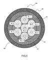
- FIG. 3 is a cross-sectional view illustrating a schematic configuration of an end face closely-arranged multi-core optical fiber 100 that can be used in the present invention.
- the end face closely-arranged multi-core optical fiber 100 includes seven optical fibers.
- each optical fiber can be manufactured by etching a single-mode fiber, which includes a core 31 having a diameter of 10 ⁇ m and a clad 32 having an outer diameter of 125 ⁇ m, with hydrogen fluoride, at a clad portion thereof, to have a clad outer diameter of 40 ⁇ m.
- the seven optical fibers are bundled together with an epoxy adhesive 33 and inserted into a bore of a ceramic-made ferrule 34. After the adhesive is hardened, the end face 101 is ground.
- the seven optical fibers are not bundled at the other end thereof.
- a non-bundled terminal end of the central optical fiber of the end face closely-arranged multi-core optical fiber 100 is connected to the signal light source.
- Non-bundled terminal ends of six peripheral optical fibers are connected to respective control light sources.
- the central optical fiber is referred to as "No. 0" optical fiber.
- the peripheral optical fibers are referred to as "No. 1" to "No. 6" optical fibers.
- FIG. 2 illustrates an example of the shape of the hexagonal truncated pyramid prism 9 to be located between the light-receiving lens 7 and the coupling lens 8.
- FIG. 2 includes a plan view positioned at an upper part thereof and a side view positioned at a lower part thereof.
- the hexagonal truncated pyramid prism 9 has the following dimensions.
- the length d of a top flat face 90 is 0.44 mm and the length D of a bottom flat face 97 is 8.6 mm.
- the thickness t of the hexagonal truncated pyramid prism 9 is 3.0 mm.
- the hexagonal truncated pyramid prism 9 is made of a glass member having a refractive index of approximately 1.5.
- a wedge angle ⁇ is, for example, 7.1 degrees or 14.0 degrees.
- the reason why the length d of the top flat face 90 is set to be 0.44 mm is because the straight-traveling signal light 10 can surely pass through the top flat face 90 when the control light passing through the thermal lens is not irradiated.
- the diameter of a light flux becomes approximately 0.4 mm if the focal length of the light-receiving lens 7 and the coupling lens 8 is 2 mm, the coupling magnification is 1, and the NA of the emission-side end face closely-arranged seven-core optical fiber bundle 100 is 0.1.
- the actual length d is set to be a slightly larger value (0.44 mm) in consideration of a Gaussian distribution of the laser beam.
- the light-receiving lens 7 and the coupling lens 8 cooperatively constitute an enlarging optical system capable of enhancing the signal light coupling efficiency of respective optical fibers that constitute the light-receiving-side seven-core optical fiber bundle 210.
- the straight-traveling signal light and the optical-path-changed signal light are not perfectly parallel when these lights are emitted from the light-receiving lens 7.
- An actual value of the length d may slightly differ from 0.4 mm. However, because of smallness in enlargement rate, these lights can be approximated as parallel light. Further, when the distance between the light-receiving lens 7 and the hexagonal truncated pyramid prism 9 is minimized, the length d is not required to be greatly changed. If the focal length of the light-receiving lens 7 and the coupling lens 8 is changed, the length d of the top flat face 90 must be changed. The length d is proportional to the focal length of lenses to be used.
- the hexagonal truncated pyramid prism 9 can change the traveling direction of the signal light again after the traveling direction has been once changed by the thermal-lens-forming optical element 1.
- the hexagonal truncated pyramid prism 9 can enlarge the distance Dx (which represents the distance between a beam spot center of the straight-traveling signal light and a beam spot center of the optical-path-changed signal light) at the position of the light-receiving-side seven-core optical fiber bundle.
- the inclined angle of the wedge is ⁇ as illustrated in FIG. 2
- the refractive index is approximately 1.5
- light having passed through the wedge travels toward a thicker side of the wedge at an inclined angle of approximately ⁇ /2 relative to the traveling direction of light in a case where no wedge is inserted.
- the distance Dx is approximately 125 ⁇ m (Dx ⁇ 2000*2 ⁇ *7.1/2/360).
- the distance Dx is proportional to the focal length of the lenses to be used. Further, the distance Dx is proportional to the inclined angle ⁇ of the wedge.
- the distance Dx can be increased, for example, to 250 ⁇ m or 300 ⁇ m by appropriately setting a combination of the above-described numerical values.
- the seven-core optical fiber bundle is a mere example of a light-receiving side detector. If the distance between the beam spot center of the straight-traveling signal light and the beam spot center of the optical-path-changed signal light at a detection position is large; e.g., when the distance Dx is equal to or greater than 400 ⁇ m, employment of the seven-core optical fiber bundle may not be desired. In this case, it is useful to use seven single-mode optical fibers respectively positioned and bonded in such a way as to optimize detection of corresponding signal light.
- the distance between the beam spot center of the straight-traveling signal light and the beam spot center of the optical-path-changed signal light at the detection position is 425 ⁇ m
- the distance between the beam spot center of the straight-traveling signal light and the beam spot center of the optical-path-changed signal light at the detection position is greater than the above-described value, it is useful to increase the outer diameter of the nickel tube.
- Component Technique S3 design of a light-receiving optical system capable of receiving the straight-traveling signal light 10 and optical-path-changed signal lights 11 to 16 emitted from the thermal-lens-forming optical element 1:
- the thermal-lens-forming optical element 1 includes a coin-type solution cell 2 that is filled with a pigment solution 3.
- the solution cell 2 is, for example, composed of two quartz discs and a quartz spacer. Each of the quartz discs and the quartz spacer has a thickness of 500 ⁇ m. The diameter of the solution cell 2 is within a range of 8 mm to 10 mm.
- a method for manufacturing the thermal-lens-forming optical element 1 includes dissolving an organic pigment, which has a maximum absorption wavelength within a range of 950 nm to 1050 nm and does not absorb light in the wavelength band of signal light (e.g., a range of 1310 nm to 1600 nm) in an organic solvent having a boiling point within a range of 290 °C to 300 °C.
- the method further includes filling the solution cell 2 with the pigment solution 3, whose concentration has been adjusted beforehand to realize an absorbance equal to or greater than 5.0 in a case where the liquid thickness is 500 ⁇ m and the wavelength of the light is 980 nm, and then hermetically closing an injection hole with the epoxy adhesive.
- the pigment solution 3 serves as a pigment absorption layer.
- a dye obtainable in the market as an infrared ray absorption pigment to be used in an infrared ray device using a YAG laser as a light source is preferably used as the above-described organic pigment.
- Any other organic pigment can be used regardless of its chemical structure if it has the above-described solubility and light absorption characteristics and does not decompose in a solution state (i.e., in a state where it is dissolved in the following solvent) even when it is irradiated with a laser having an absorption wavelength band for a long time and further even when the temperature instantaneously increases up to 300 °C.
- the mixed solvent containing the above-described four structural isomer components is preferably used for the thermal-lens-forming optical element 1, because the viscosity of this solvent and temperature dependence of the viscosity are extremely small compared to other organic solvents having a boiling point of approximately 300°C.
- the above-described mixed solvent is disadvantageous in that it tends to be oxidized by oxygen molecules in the air. As described above, this problem can be solved by performing purification processing beforehand to remove dissolved oxygen molecules, so that the solution cell 2 is filled with the purified pigment solution 3.
- the upper limit of the control light power is variable depending on the boiling point of the pigment solution using the above-described solvent. More specifically, if the control light power increases, transmission of the signal light is prevented by generation of bubbles when the maximum temperature of a thermal-lens-forming area reaches the boiling point of the solvent.
- micro bubbles may generate before the temperature reaches the boiling point and scatter the signal light beam in such a way as to increase the beam diameter.
- the upper limit of the control light power it is desired to set the upper limit of the control light power to be 5% to 10% lower than the boiling initiation level, before the control light enters the thermal-lens-forming optical element 1.
- control light output may oscillate due to a temperature change of the control light source.
- control light output may reach the boiling initiation level due to variation of the output if the control light power is only 5% lower than the boiling initiation level.
- the upper limit of the control light power is set to be 8% to 10% lower than the boiling initiation level, before the control light enters the thermal-lens-forming optical element 1.
- a desired value of the control light power is variable depending on design conditions of a condensing optical system configured to converge the control light and the signal light into the thermal-lens-forming optical element 1, which is, for example, the reducing optical system composed of the lenses 5 and 6 illustrated in FIG. 1 .
- the control light power is set in a range of approximately 20 mW to 50 mW as an absolute value.
- the pigment solution may start boiling. Switching of the signal light between seven directions is feasible while preventing the boiling of the pigment solution, in the best condition described in the present embodiment, when the coupling efficiency relative to the light-receiving-side optical fiber is equal to or greater than 60% and the crosstalk between neighboring channels is equal to or less than -30 dB.
- the power of the control light to be input to the thermal-lens-forming optical element 1 is not influenced by the focal length of the lenses 5 and 6.
- an anti-reflection coating on the surfaces of the optical components to be used (i.e., the lens, the thermal-lens-forming optical element, the hexagonal truncated pyramid prism, etc.) as well as the end faces of the emission-side end face closely-arranged seven-core optical fiber bundle and the light-receiving-side seven-core optical fiber bundle.
- An appropriate conventionally-known element can be used as an anti-reflection coating material.
- the reducing optical system that can reduce the distance (e.g., 40 ⁇ m) between the optical axis of the signal light and the optical axis of the control light on the output side of the emission-side end face closely-arranged seven-core optical fiber bundle to a short distance within a range of 20 ⁇ m to 25 ⁇ m at the incidence position on the light-absorbing layer (pigment solution) of the thermal-lens-forming optical element 1.
- the incidence efficiency of the optical-path-changed signal light into the light-receiving-side optical fiber decreases due to collapse of the beam cross-sectional shape.
- FIG. 6 illustrates examples of the distance between the optical axes (i.e., the distance between the signal light and the control light at the condensing point in the direction perpendicular to the optical axis) in relation to a corresponding optical path change amount (i.e., the optical-path-changing angle) in the light-absorbing layer. If the distance between the optical axes becomes shorter, the optical-path-changing angle becomes larger. If the optical-path-changing angle becomes larger, the straight-traveling signal light and the optical-path-changed signal light can be efficiently separated and the crosstalk of a detected signal (information) can be reduced.
- the distance between the optical axes i.e., the distance between the signal light and the control light at the condensing point in the direction perpendicular to the optical axis
- a corresponding optical path change amount i.e., the optical-path-changing angle
- a low-density portion moves upward (i.e., the direction opposite to gravity) due to heat convection occurring in a fluid.
- the thermal lens area Accordingly, to stabilize the shape of the thermal lens area and maximize the thermal lens effects, it is useful to perform the following setting in determining the setup orientation of the thermal-lens-forming optical element 1 relative to the direction of gravity and also in determining the directions of the signal light and the control light incident on the thermal-lens-forming optical element 1 relative to the direction of gravity.
- the signal light incidence plane of the thermal-lens-forming optical element 1 is set to be perpendicular to the direction of gravity. Further, the traveling directions of the signal light and the control light incident on the thermal-lens-forming optical element are set to be parallel to the direction of gravity.
- the shape of a thermal lens to be formed and the influence given to the signal light can be rendered uniform.
- the signal light incidence plane of the thermal-lens-forming optical element can be set to be parallel to the direction of gravity and the traveling directions of the signal light and the control light incident on the thermal-lens-forming optical element can be set to be perpendicular to the direction of gravity.
- the signal light incidence plane of the thermal-lens-forming optical element 1 can be set to be perpendicular to the direction of gravity and the traveling directions of the signal light and the control light incident on the thermal-lens-forming optical element 1 can be set to be opposite to the direction of gravity.
- the usage efficiency of the thermal lens effects deteriorates as compared with the present embodiment.
- the changing degree of the optical path may vary depending on the irradiation position of the control light, or the beam position of the optical-path-changed signal light may move in response to a temporal variation of the thermal lens effects.
- the distance between the optical axis of the signal light emitted from the central optical fiber of the emission-side end face closely-arranged seven-core optical fiber bundle 100 and the optical axis of the control light emitted from the peripheral optical fiber is set to, for example, 40 ⁇ m.
- the thermal lens effects can be maximized by the reducing projection optical system composed of the collimator lens 5 and the condensing lens 6 in the following manner.
- the reducing projection optical system guides the control light and the signal light to converge into the light-absorbing layer (pigment solution) of the thermal-lens-forming optical element 1 in such a way as to differentiate respective convergence points in a direction perpendicular to the optical axis.
- the distance between the optical axis of the signal light and the optical axis of the control light can be reduced to a short distance within a range of 20 ⁇ m to 30 ⁇ m.
- two convex lenses having the same focal length as the collimator lens 5 and the condensing lens 6 it is desired to appropriately combine two convex lenses having the same focal length as the collimator lens 5 and the condensing lens 6.
- two non-spherical convex lenses each having a focal length of 2 mm and a numerical aperture (NA) of 0.5 can be combined and employed as the collimator lens 5 and the condensing lens 6 that constitute the reducing optical system.
- FIGS. 5A , 5B , and 5C illustrate examples of an optical-path-changed state of the signal light due to irradiation with the control light.
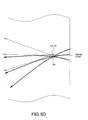
- FIG. 5D is an enlarged view illustrating a portion encircled by a line having alternating long and two short dashes in FIG. 5B .
- the refraction of light is not taken into consideration in FIGS. 5A , 5B , and 5C , although the refraction of light occurs if the refractive index of the light-absorbing layer 3 is different from the refractive index of the solution cell 2 surrounding the light-absorbing layer.
- FIGS. 5A , 5B , and 5C illustrate a light intensity distribution 81 of the control light at or near the convergence (condensing) point and a light intensity distribution 82 of the control light at a position far from the convergence (condensing) point, in the light-absorbing layer 3 of the thermal-lens-forming optical element 1.
- FIGS. 5A , 5B , and 5C illustrate a light intensity distribution 81 of the control light at or near the convergence (condensing) point and a light intensity distribution 82 of the control light at a position far from the convergence (condensing) point, in the light-absorbing layer 3 of the thermal-lens-forming optical element 1.
- FIGS. 5A , 5B , and 5C illustrate a light intensity distribution 81 of the control light at or near the convergence (condensing) point and a light intensity distribution 82 of the control light at a position far from the convergence (condensing) point, in the light-absorbing layer 3 of the thermal-lens
- 5A , 5B , and 5C further illustrate a convergence (condensing) point 83 of the control light, a convergence (condensing) point 85 of the signal light in the absence of irradiation with the control light, a convergence (condensing) point 86 of the signal light in the presence of irradiation with the control light, and an apparent convergence (condensing) point 84 of the signal light.
- FIG. 5A illustrates convergence (condensing) of the control light and the signal light on the incidence plane of the light-absorbing layer 3.
- FIG. 5B illustrates convergence (condensing) of the control light and the signal light at a point positioned inward (several tens of micrometers) relative to the incidence plane of the light-absorbing layer 3.
- FIG. 5C illustrates convergence (condensing) of the control light and the signal light at a further inner position far from the incidence plane of the light-absorbing layer 3.
- the signal light In the absence of irradiation with the control light, the signal light travels straight. In the presence of irradiation with the control light, the signal light changes its optical path.
- the signal light having passed through the light-absorbing layer 3 converges (condenses) on detectors 201 to 206 illustrated in FIG. 1 , as if the signal light is emitted from the apparent convergence (condensing) point 84 of the signal light in the light-absorbing layer 3 illustrated in FIG. 5A to 5D .
- the convergence (condensing) point 85 of the signal light in the absence of irradiation with the control light coincides with the convergence (condensing) point 86 of the signal light in the presence of irradiation with the control light.
- the apparent convergence (condensing) point 84 of the signal light is spaced from the convergence (condensing) point 85 (or 86).
- the signal light is converged (condensed) into the thermal-lens-forming optical element.
- the signal light bends greatly at a portion positioned closely to the control light and is greatly influenced by the control light.
- the signal light does not bend so greatly at a portion spaced far from the control light.
- the beam diameter is smallest on the incidence plane and gradually increases with increasing distance from the incidence plane. Therefore, according to the example illustrated in FIG. 5A , the signal light is constantly and greatly influenced by the control light at the same portion positioned closely to the control light. Accordingly, in this case, the beam cross-sectional shape of the converged (condensed) signal light becomes a crescent, not a circle.
- the positional relationship between the control light and the signal light is not different from that illustrated in FIG. 5A .
- the position of the light-absorbing layer 3 is slightly offset toward the incidence side of the control light and the signal light. Therefore, the control light and the signal light converge (condense) at the point positioned inward relative to the light-absorbing layer 3.
- the convergence (condensing) point 85 of the signal light in the absence of irradiation with the control light can be set to substantially coincide with the apparent convergence (condensing) point 84 of the signal light.
- the convergence (condensing) point 84 coincides with the convergence (condensing) point 85.
- the convergence (condensing) point 86 is slightly spaced from the convergence (condensing) point 84 (or 85).
- influence of the control light can be rendered uniform, because the portion of the signal light positioned closely to the control light is switched at the convergence (condensing) point 86. Therefore, it is believed that the beam cross-sectional shape of the converged (condensed) signal light becomes a circle without causing any distortion.
- control light and the signal light converge (condense) at the further inner far from the incidence plane of the light-absorbing layer 3.
- the apparent convergence (condensing) point 84 of the signal light substantially coincides with the convergence (condensing) point 86 of the signal light in the presence of irradiation with the control light.
- the control light is absorbed by the thermal-lens-forming optical element 1 when the control light travels in the thermal-lens-forming optical element 1. Therefore, the quantity of light gradually decreases and the thermal lens effects cannot be obtained at the inner position spaced (e.g., 200 ⁇ m to 300 ⁇ m) from the incidence plane.
- the signal light condenses at the position where the signal light is not substantially influenced by the control light. Therefore, the signal light does not bend after passing through the convergence (condensing) point 86. However, the signal light bends largely before the signal light reaches the convergence (condensing) point 86, because the signal light is greatly influenced by the control light at a portion opposite the portion illustrated in FIG. 5A . Therefore, it is believed that the beam cross-sectional shape of the signal light does not become a circle.
- a positional adjustment for the thermal-lens-forming optical element 1; i.e., the light-absorbing layer 3, is performed to keep the beam cross section of the optical path changed signal light as a circular beam, as illustrated in FIG. 5B .
- the hexagonal truncated pyramid prism is not provided, the straight signal light whose traveling direction has not been changed due to lack of irradiation with the control light and the signal light whose optical path has been changed due to irradiation with the control light converge (condense) to the same point at a light-receiving position of the detector.
- the optical path switching is performed keeping a circular beam cross-sectional shape of the signal light to improve the coupling efficiency
- the convergence (condensing) point 85 of the signal light in the absence of irradiation with the control light coincides with the apparent convergence (condensing) point 84 of the signal light.
- the positional relationship between two convergence (condensing) points 85 and 84 is "fixed.” Therefore, it is difficult to separately detect the straight-traveling signal light and the optical-path-changed signal light.
- the hexagonal truncated pyramid prism 9 between the light-receiving lens 7 and the coupling lens 8.
- the hexagonal truncated pyramid prism 9 enables the straight-traveling signal light to travel straight without causing any bending.
- the hexagonal truncated pyramid prism 9 causes the optical-path-changed signal light to travel at an inclined angle relative to the straight-traveling signal light.
- the straight-traveling signal light and the optical-path-changed signal light can be received and detected, with higher coupling efficiency, using different optical fibers located at sufficiently spaced positions.
- the crosstalk of the straight-traveling signal light and the optical-path-changed signal light can be greatly reduced.
- the beam positions of the straight-traveling signal light and the optical path switched light can be greatly changed without using the wedge prism.
- the beam cross-sectional shape of the optical-path-changed signal light greatly deviates from a circular beam having the Gaussian distribution. Therefore, the coupling efficiency greatly decreases when the signal light is received and detected by the optical fiber. Further, the signal light itself greatly attenuates and cannot be practically used.
- the first design setting factor includes a setting of the light-receiving lens 7 (first light-receiving unit) that receives the straight-traveling signal light (i.e., signal light in the absence of irradiation with the control light) 10 and the optical-path-changed signal light (i.e., signal light in the presence of irradiation with control lights 21 to 26) 11 to 16 emitted from the thermal-lens-forming optical element 1.
- the first design setting factor further includes a setting of the coupling lens 8 (the second light-receiving unit) that couples the straight-traveling signal light 10 and the optical-path-changed signal lights 11 to 16 to the core of the fiber end face of the light-receiving-side seven-core optical fiber bundle 210.
- the wavelength of the signal light is 1490 nm to be used as a downlink signal and 1310 nm to be used as an uplink signal according to the Fiber To The Home (FTTH), which are influenced by the refractive index wavelength dependency of lenses. If the optical system is optimized for one wavelength in the absence of achromatic lenses, the optical fiber coupling efficiency decreases at the other wavelength.
- FTTH Fiber To The Home
- Table 1 illustrates experimentally obtained optical fiber coupling efficiency measured at three focal lengths of 8 mm, 2.75 mm, and 2.0 mm under the condition that the light-receiving lens 7 and the coupling lens 8 have the same focal length. As apparent from the table 1, when the focal length is equal to or less than 2.75 mm, the wavelength dependence of the optical fiber coupling efficiency becomes extremely smaller.
- the optical fiber coupling efficiency measured with 1310 nm light is smaller than the coupling efficiency measured with 1550 nm light.
- the optical fiber coupling efficiency measured with 1550 nm light is smaller than the coupling efficiency measured with 1310 nm light.
- the minimum focal length of the light-receiving lens 7 and the coupling lens 8 is practically 1.0 mm. If the focal length is set to a smaller value, the lens 7 or 8 may collide against the hexagonal truncated pyramid prism 9 when the lens moves.
- the light-receiving lens 7 (the first light-receiving unit) and the light-receiving lens 8 (the second light-receiving unit) are spherical or non-spherical convex lenses having a focal length of 1.0 mm to 3.0 mm, there is not any influence by the wavelength difference of the signal light even when achromatic lenses are not used.
- the signal light passing through the thermal-lens-forming optical element 1 is condensed to the light-receiving-side seven-core optical fiber bundle by the light-receiving lens 7 and the coupling lens 8.
- the reducing optical system is composed of two convex lenses of the collimator lens 5 and the condensing lens 6, it is desired to enlarge the signal light when condensed by the light-receiving lens 7 and the coupling lens 8 so that the light-receiving-side seven-core optical fiber bundle can efficiently detect the signal light.
- the signal light is reduced by the collimator lens 5 and the condensing lens 6 at a reduction rate of 0.8, it is desired to enlarge the signal light by the light-receiving lens 7 and the coupling lens 8 at an enlargement rate of 1.25.
- the coupling efficiency is relatively small when the focal length of the lens is 8 mm, because it is difficult to optimize the enlargement rate by the light-receiving lens 7 and the coupling lens 8.
- the distance between the coupling lens 8 and the hexagonal truncated pyramid prism 9 is required to enable the signal light, whose optical path has been switched due to irradiation with the control light, having passed through the hexagonal truncated pyramid prism 9 to pass through a point near an incidence-side focal point of the coupling lens 8 so that the signal light can vertically reach the end face of respective single-mode optical fibers serving as detectors 200 to 206.
- the distance between the light-receiving lens 7 and the coupling lens 8 cannot be set to an extremely small value.
- the second design setting factor includes the wedge to be inserted between the light-receiving lens 7 and the coupling lens 8.
- the seven-core optical fiber bundle it is desired to integrate six pieces of wedges to be required as the hexagonal truncated pyramid prism 9 illustrated in FIG. 2 .
- the straight-traveling signal light 10 enters the hexagonal truncated pyramid prism 9 from the top flat face 90 and exits from the bottom surface 97.
- the optical-path-changed signal lights 11 to 16 pass through wedge faces 91 to 96 positioned around the top flat face 90 and are refracted in such a way as to increase the distance between the optical axis of the straight-traveling signal light and the optical axis of the optical-path-changed signal light.
- the second design setting factor further includes a setting for preventing the beam spot of the optical-path-changed signal light from overlapping with the beam spot of the straight-traveling signal light at an image-forming position.
- the above-described setting is effective to reduce the crosstalk between the straight-traveling signal light and the optical-path-changed signal light as well as the crosstalk between the neighboring optical-path-changed signal lights.
- the reducing optical system is composed of two convex lenses of the collimator lens 5 and the condensing lens 6. It is desired to enlarge the signal light when condensed by the light-receiving lens 7 and the coupling lens 8 so that the light-receiving-side seven-core optical fiber bundle can efficiently detect the signal light.
- the signal light is reduced by the collimator lens 5 and the condensing lens 6 at a reduction rate of 0.8, it is desired to enlarge the signal light by the light-receiving lens 7 and the coupling lens 8 at an enlargement rate of 1.25.
- the light-receiving lens 7 and the coupling lens 8 have a focal length of 2 mm and the distance between the light-receiving lens 7 and the coupling lens 8 is set to 20 mm so as to realize 1.25 times enlargement of the signal light, approximately 0.3 degrees of condensing of light occurs when the light has passed through the light-receiving lens 7.
- the signal light deviates from the parallel light due to increase of the enlargement rate, aberration of the signal light occurs when the signal light passes through the wedge portion of the hexagonal truncated pyramid prism 9.
- the focal length of the light-receiving lens 7 and the focal length of the coupling lens 8 are changed so as to realize the enlargement, the signal light can remain as parallel light and can pass through the hexagonal truncated pyramid prism 9 without causing any aberration.
- the signal light travels straight and reaches the top flat face portion. Namely, the signal light travels straight without changing its optical path.
- the hexagonal truncated pyramid prism 9 is set in such a manner that the optical-path-changed signal light having passed through the wedge portion of the hexagonal truncated pyramid prism 9 travels in a direction intersecting with the straight-traveling signal light in the absence of irradiation with the control light.
- the distance between the hexagonal truncated pyramid prism 9 and the coupling lens 8 is set in such a manner that the signal light having passed through the hexagonal truncated pyramid prism 9 can vertically reach the end face of respective single-mode optical fibers (light-receiving-side seven-core optical fibers 200 to 206), after passing through the coupling lens 8.
- the signal light whose optical path has been changed by the wedge can pass through the incidence side focal point of the coupling lens 8.
- the incidence efficiency of the signal light can be maximized at the detector (optical fiber).
- the single-mode optical fibers (the detectors 200 to 206) are set to be substantially parallel to the optical axis.
- the prism may be configured to have a shape different from the above-described hexagonal truncated pyramid shape.
- the prism may be a flat glass member recessed at the center thereof so as to have a reversed hexagonal truncated pyramid shape.
- the top flat face serves as an incidence plane and the bottom flat face serves as an emission plane.
- the hexagonal truncated pyramid prism 9 can be placed upside down so that the top flat face can serve as an emission plane and the bottom flat face can serve as an incidence plane.
- the third design setting factor includes a setting of the wedge (wedge) angle ⁇ of the hexagonal truncated pyramid prism 9 and a determination of the distance between the centers of the peripheral fibers constituting the light-receiving-side seven-core optical fiber bundle.
- the distance Rout between the optical axis of the straight-traveling signal light and the optical axis of the optical-path-changed signal light at the position of the detector can be calculated based on the inclined angle ⁇ of the hexagonal truncated pyramid prism 9 and the focal length f of the coupling lens 8 in the following manner.
- Rout f * tan ⁇ out
- ⁇ out represents an emission angle of the light from the hexagonal truncated pyramid prism 9 (i.e., an angle relative to a line perpendicular to the top flat face of the hexagonal truncated pyramid prism 9, which takes a positive value when it crosses the vertical line).
- the emission angle ⁇ out can be given in the following manner. [Numerical Expression 2] ⁇ out ⁇ 2 * n 1 / n 0 - 1 * ⁇ / 2 + ⁇ in
- n 1 represents a refractive index of the hexagonal truncated pyramid prism 9
- no represents a refractive index of a medium (e.g., the air in the present embodiment) that surrounds the hexagonal truncated pyramid prism 9
- ⁇ represents an inclined angle of the hexagonal truncated pyramid prism 9.
- ⁇ in represents an incident angle of the light entering the hexagonal truncated pyramid prism 9 (i.e., an angle relative to a line perpendicular to the top flat face of the hexagonal truncated pyramid prism 9, which takes a positive value when it crosses the vertical line and takes a negative value when it departs from the vertical line).
- the signal light having passed through the hexagonal truncated pyramid prism 9 enters and passes through the coupling lens 8, and then vertically enters the single-mode optical fiber (i.e., the detector) from the end face thereof.
- the distance X between the coupling lens 8 and the hexagonal truncated pyramid prism 9 can be calculated in the following manner.
- the distance X between the coupling lens 8 and the hexagonal truncated pyramid prism 9, which can maximize the incidence efficiency of the light entering the optical fiber (i.e., detector), can be obtained as a sum of the focal length f of the coupling lens 8 that converges (condenses) the light into the optical fiber (i.e., the detector) and a value obtained by diving the distance r 1 of the incidence light on the hexagonal truncated pyramid prism 9 from the optical axis by a tangential value of the inclined angle of the hexagonal truncated pyramid prism 9.
- the distance X between the coupling lens 8 and the hexagonal truncated pyramid prism 9 is approximately 9 mm.
- the above-described calculation is based on the assumption that the single-mode optical fibers (i.e., the detectors 200 to 206) are set to be substantially parallel to the optical axis. If the single-mode optical fibers (i.e., the detectors 200 to 206) are not parallel to the optical axis, the inclination of the optical axis must be corrected.
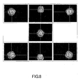
- FIG. 8 illustrates beam cross sections of the straight-traveling signal light and the optical-path-switched signal lights, which can be observed when the following conditions are satisfied.
- the distance between the optical axis of the control light and the optical axis of the signal light is 25 ⁇ m.
- the signal light first enters the light-absorbing layer of the thermal-lens-forming optical element 1. Then, after passing through the thermal-lens-forming optical element 1, a straight-traveling signal light beam and optical-path-switched signal light beams reach and pass through the hexagonal truncated pyramid prism having a wedge angle of 7 degrees. Finally, the signal light reaches a light-receiving surface of a beam profiler.
- Fig. 8 it is understood that the optical path switching between seven directions can be realized without deforming a circular shape of each beam.
- any one of the control lights 21 to 26 (e.g., the control light 21) intermittently turns on and off at a duty ratio 1:1.
- the frequency is changed within a range of 50 Hz to 2000 Hz.
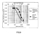
- FIG. 9 is a graph plotting a value (hereinafter, referred to as "amplitude") obtained as a ratio of the intensity of the straight-traveling signal light and the optical-path-changed signal light in the above-described state to the intensity of the signal light in a reference state where the control light is continuously turned on or off.
- the control light 21 intermittently turns on and off at the frequency of 50 Hz (i.e., with a period of 20 milliseconds)
- the intensity of the straight-traveling light and the optical-path-changed light is identical to the intensity of the signal light in the reference state where the control light is continuously turned on or off. Therefore, the amplitude is equal to 1.0.
- the intensity of the straight-traveling light and the optical-path-changed light changes from 0.0 to 1.0, or vice versa, according to the turning on and off of the control light, during a half of the period (i.e., 10 milliseconds).
- a half (1/2) of a reciprocal of the frequency i.e., a half of the period
- response time in the signal light optical-path-switching operation that corresponds to the turning on and off of the control light.
- the optical-path-changed light reaches the amplitude level of 1.0 faster than does the straight-traveling light.
- the response time required to reach the amplitude level of 1.0 is approximately 5 milliseconds in the case of the straight-traveling light and 2.5 milliseconds in the case of the optical-path-changed light.
- the response time of an ordinary electric switch is equal to a time required to reach a signal intensity level of 1/ ⁇ 2; i.e., an amplitude level of 0.707.
- an optical-path-switching time is equal to a response time required to reach an amplitude level of approximately 0.7
- the optical-path-switching time is approximately 2.5 milliseconds in the case of the straight-traveling light and approximately 0.9 milliseconds in the case of the optical-path-switched light.
- adjustment of the optical system is performed in such a way as to optimize the response time in an optical-path-switching operation.
- the crosstalk between channels in a one-to-seven type optical-path-switching operation and the coupling efficiency of the light-receiving-side optical fiber i.e., insertion loss of the optical-path-switching apparatus
- the crosstalk between channels in a one-to-seven type optical-path-switching operation and the coupling efficiency of the light-receiving-side optical fiber are important optical-path-switching characteristics.
- the signal light incidence plane of the thermal-lens-forming optical element 1 is set to be parallel to the direction of gravity and the traveling directions of the signal light and the control light incident on the thermal lens-forming-optical element 1 are set to be perpendicular to the direction of gravity.
- the layout of the peripheral optical fibers No. 1 to No. 6 constituting the emission-side end face closely-arranged seven-core optical fiber bundle 100 corresponds to the layout of the peripheral optical fibers No. 1 to No. 6 constituting the light-receiving-side seven-core optical fiber bundle.
- the peripheral optical fibers No. 1 and No. 2 are positioned on the lower side thereof and the peripheral optical fibers No. 4 and No. 5 are positioned on the upper side thereof.
- Optical components constituting the apparatus are basically similar to those described in the first embodiment.
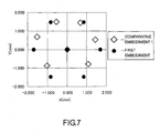
- FIG. 7 illustrates beam positions of the straight-traveling signal light and the optical-path-switched signal lights actually measured at the position of the light-receiving lens 7 of the beam profiler (not illustrated), when the straight-traveling signal light 10 and the optical-path-switched signal lights 11 to 16 are emitted from the thermal-lens-forming optical element 1.
- each black circular mark indicates a beam position actually measured using the system according to the first embodiment and each square mark indicates a beam position actually measured using the system according to comparative embodiment 1.
- the hexagonal shape connecting the beam positions of the optical-path-changed signal lights is a flat hexagonal shape that is compressed in the up-and-down direction (not a regular hexagonal shape), because the thermal-lens-forming optical element 1 is parallel to the direction of gravity and the traveling direction of the control light is perpendicular to the direction of gravity.
- a low-density thermal lens area formed in the light-absorbing layer of the thermal-lens-forming optical element 1 "floats (moves upward)" in the solution cell. Therefore, if the signal light is positioned higher than the control light in the thermal lens, the signal light is subjected to greater thermal lens effects.
- ⁇ in has a negative value and ⁇ out becomes smaller. As a result, the distance Rout becomes smaller as understood from Formula (1).
- the signal light is positioned lower than the control light in the thermal lens, the signal light is subjected to slightly smaller thermal lens effects.
- the influence is not so remarkably large as compared to the case where the signal light is positioned higher than the control light in the thermal lens.
- the influence of heat convection is substantial negligible in the "right-and-left" direction of FIG. 7 .
- the signal light incidence plane of the thermal-lens-forming optical element 1 is set to be perpendicular to the direction of gravity and the traveling directions of the signal light and the control light incident on the thermal-lens-forming optical element 1 are set to be opposite to the direction of gravity.
- the remaining features relating to the optical components are similar to those described in the first embodiment.
- the thermal lens effects obtained by comparative embodiment 2 are very small compared to the thermal lens effects obtained in the first embodiment.
- the distance between an image formed by the straight-traveling signal light and an image formed by the optical-path-changed signal light is smaller than that expressed using the black circular marks in FIG. 7 .
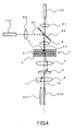
- FIG. 4 illustrates a schematic configuration of the optical-path-switching apparatus according to a second embodiment of the present invention.
- the second embodiment is characterized in that the emission-side end face closely-arranged seven-core optical fiber bundle 100 used in the first embodiment is replaced by a dichromatic mirror 55.
- the distance between the optical axis of the collimated signal light 20 and the optical axis of collimated control light 27 is set to fall within a range of 20 ⁇ m to 25 ⁇ m, so that the converged light can enter the light-absorbing layer of the thermal-lens-forming optical element 1.
- the second embodiment differs from the first embodiment in that the light-receiving-side seven-core optical fiber bundle 210 is replaced by a straight-traveling signal-light-receiving optical fiber 220 and an optical-path-changed signal light-receiving optical fiber 221.
- the remaining elements of the optical-path-switching apparatus according to the second embodiment are similar to those described in the first embodiment.
- the optical-path-switching apparatus is a one-to-two type optical-path-switching apparatus that is configured to emit signal light and control light downward along the direction of gravity.
- the second embodiment can bring effects similar to those described in the first embodiment, although the method for mixing the signal light and the control light (whose optical axes do not coincide with each other) is different.
Landscapes
- Physics & Mathematics (AREA)
- Nonlinear Science (AREA)
- General Physics & Mathematics (AREA)
- Optics & Photonics (AREA)
- Optical Modulation, Optical Deflection, Nonlinear Optics, Optical Demodulation, Optical Logic Elements (AREA)
- Optical Couplings Of Light Guides (AREA)
Claims (7)
- Lichtwegumschaltvorrichtung, umfassend:eine Signallichtquelle, um Signallicht zu generieren, das eine oder mehrere Arten von Wellenlängen aufweist;zwei oder mehrere Steuerlichtquellen, um Steuerlicht zu generieren, das eine spezifische Wellenlänge aufweist, die anders als die des Signallichts ist;ein eine thermische Linse bildendes optisches Element (1), das eine Licht absorbierende Schicht (3) umfasst, um das Signallicht durchzulassen und das Steuerlicht selektiv zu absorbieren; undeine Konzentrationseinheit (5, 6), um das Steuerlicht und das Signallicht zu leiten, damit sie derart in die Licht absorbierende Schicht konvergieren, dass sie jeweilige Konvergenzpunkte in einer Richtung rechtwinklig zur optischen Achse unterscheiden,wobei das eine thermische Linse bildende optische Element (1) geeignet ist, um zu bewirken, dass das Steuerlicht und das Signallicht in die Licht absorbierende Schicht konvergieren und sich dann in der Ausbreitungsrichtung des Lichts derart verbreiten, dass sie auf Grund eines Temperaturanstiegs, der stellenweise in einem Bereich, in dem das Steuerlicht absorbiert wird, und in seinem Umfangsbereich in der Licht absorbierenden Schicht erfolgt, vorübergehend eine thermische Linse bilden, und die thermische Linse geeignet ist, um eine Brechungsindexverteilung in der Licht absorbierenden Schicht (3) zu generieren, um die Ausbreitungsrichtung des Signallichts derart zu ändern, dass eine Lichtwegumschaltung ausgeführt wird,wobei eine erste Licht empfangende Einheit (7) und eine zweite Licht empfangende Einheit (8) bereitgestellt werden, so dass sich geradliniges Signallicht, dessen Ausbreitungsrichtung auf Grund fehlender Bestrahlung mit dem Steuerlicht nicht geändert wurde, geradlinig durch die erste Licht empfangende Einheit und die zweite Licht empfangende Einheit hindurch ausbreitet, und ein Signallicht, dessen Lichtweg auf Grund einer Bestrahlung mit dem Steuerlicht umgeschaltet wurde, von der ersten Licht empfangenden Einheit und der zweiten Licht empfangenden Einheit konvergiert oder konzentriert wird, die aus identischen optischen Elementen bestehen,gekennzeichnet durch:ein Keilprisma (9), das zwischen der ersten Licht empfangenden Einheit und der zweiten Licht empfangenden Einheit bereitgestellt wird, um das geradlinige Signallicht, dessen Ausbreitungsrichtung auf Grund fehlender Bestrahlung mit dem Steuerlicht nicht geändert wurde, und das Signallicht, dessen Lichtweg auf Grund der Bestrahlung mit dem Steuerlicht umgeschaltet wurde, zu brechen und dabei einen Lichttrennungszustand zu bewahren, und fernerwobei mindestens eine der folgenden Bedingungen 1 bis 4, jedoch mindestens Bedingung 2, erfüllt ist:1: die Konzentrationseinheit bewirkt, dass sich das Steuerlicht und das Signallicht auf der Einfallsebene der Licht absorbierenden Schicht derart konzentrieren, dass sie jeweilige Konvergenzpunkte in der Richtung rechtwinklig zur optischen Achse unterscheiden und ein reduzierendes optisches Projektionssystem bilden,2: das Keilprisma weist mindestens eine Keilfläche (91 bis 96) auf, die in einem Abschnitt bereitgestellt wird, der jeder Durchgangsposition des Signallichts mit umgeschaltetem Lichtweg entspricht,3: das Keilprisma weist mindestens eine Keilfläche auf, die an einem Abschnitt bereitgestellt wird, die jeder Durchgangsposition des Signallichts mit umgeschaltetem Lichtweg entspricht, um das Signallicht mit umgeschaltetem Lichtweg derart zu brechen, dass ein Abstand zwischen der optischen Achse des Signallichts mit umgeschaltetem Lichtweg und der optischen Achse des geradlinigen Signallichts, dessen Ausbreitungsrichtung auf Grund fehlender Bestrahlung mit dem Steuerlicht nicht geändert wurde, reduziert wird, und4: das eine thermische Linse bildende optische Element ist derart positioniert, dass wenn kein Keilprisma bereitgestellt wird, das sich geradlinig ausbreitende Signallicht und das Signallicht mit umgeschaltetem Lichtweg von der ersten Licht empfangenden Einheit und der zweiten Licht empfangenden Einheit auf die gleiche Position konvergiert oder konzentriert werden.
- Lichtwegumschaltvorrichtung nach Anspruch 1, wobei das Signallicht und das Steuerlicht in das eine thermische Linse bildende optische Element (1) über die Einfallsebene eintreten, die auf einer oberen Seite des eine thermische Linse bildenden optischen Elements positioniert ist.
- Lichtwegumschaltvorrichtung nach Anspruch 1 oder 2, ferner umfassend:ein endseitig dicht angeordnetes mehradriges Lichtleitfaserbündel (100), um das geradlinige Signallicht, dessen Ausbreitungsrichtung nicht geändert wurde, und das Signallicht, dessen Lichtweg umgeschaltet wurde, zu empfangen, die von der zweiten Licht empfangenden Einheit (8) konvergiert oder konzentriert werden.
- Lichtwegumschaltvorrichtung nach einem der Ansprüche 1 bis 3, ferner umfassend:ein endseitig dicht angeordnetes siebenadriges Lichtleitfaserbündel (100), das eine mittlere Lichtleitfaser umfasst, die ein nicht gebündeltes Kabelende, das an die Signallichtquelle angeschlossen ist, und sechs umlaufende Lichtleitfasern, die nicht gebündelte Kabelenden aufweisen, die jeweils an zwei bis sechs Steuerlichtquellen angeschlossen sind, die jeweils Steuerlicht generieren, das eine andere Wellenlänge als die des Signallichts hat, aufweist.
- Lichtwegumschaltvorrichtung nach einem der Ansprüche 1 bis 4, wobei das Keilprisma (9) ein sechseckiges Pyramidenstumpfprisma ist, das in der Lage ist zu bewirken, dass das geradlinige Signallicht, dessen Ausbreitungsrichtung auf Grund fehlender Bestrahlung mit dem Steuerlicht nicht geändert wurde, senkrecht durch eine obere flache Seite (90) des sechseckigen Pyramidenstumpfprismas (9) geht, und dabei bewirkt, dass das Signallicht, dessen Lichtweg umgeschaltet wurde, durch eine der sechs Keilflächen (91 bis 96) des sechseckigen Pyramidenstumpfprismas geht, wodurch bewirkt wird, dass jedes Licht aus dem sechseckigen Pyramidenstumpfprisma austritt.
- Lichtwegumschaltvorrichtung nach einem der Ansprüche 1 bis 5, wobei die erste Licht empfangende Einheit (7) und die zweite Licht empfangende Einheit (8) sphärische oder nicht sphärische konvexe Linsen sind, die eine Brennweite in einem Bereich von 1,0 mm bis 3,0 mm aufweisen.
- Verfahren zum Umschalten des Lichtwegs eines Lichtsignals, umfassend folgende Schritte:Bewirken, dass eine Signallichtquelle Signallicht generiert, das eine oder mehrere Arten von Wellenlängen aufweist;Bewirken, dass zwei oder mehrere Steuerlichtquellen, Steuerlicht generieren, das eine spezifische Wellenlänge aufweist, die anders als die des Signallichts ist;Leiten des Steuerlichts und des Signallichts, damit sie in eine Licht absorbierende Schicht (3) eines eine thermische Linse bildenden optischen Elements (1) konvergieren, das in der Lage ist, das Signallicht durchzulassen und das Steuerlicht selektiv zu absorbieren, so dass jeweilige Konvergenzpunkte in einer Richtung rechtwinklig zur optischen Achse unterschieden werden,Bewirken, dass das Signallicht an das eine thermische Linse bildende optische Element durchgelassen wird;Bewirken, dass das Steuerlicht in der Licht absorbierenden Schicht des eine thermische Linse bildenden optischen Elements derart absorbiert wird, dass es provisorisch auf Grund eines Temperaturanstiegs, der stellenweise in einem Bereich erfolgt, in dem das Steuerlicht absorbiert wird, und in seinem Umfangsbereich in der Licht absorbierenden Schicht, eine thermische Linse bildet, und Bewirken, dass die thermische Linse eine Brechungsindexverteilung in der Licht absorbierenden Schicht generiert, um die Ausbreitungsrichtung des Signallichts derart zu ändern, dass eine Lichtwegumschaltung erfolgt;Bewirken, dass sich geradliniges Signallicht, dessen Ausbreitungsrichtung auf Grund fehlender Bestrahlung mit dem Steuerlicht nicht geändert wurde, geradlinig durch eine erste Licht empfangende Einheit (7) und eine zweite Licht empfangende Einheit (8) ausbreitet, und Bewirken, dass die erste Licht empfangende Einheit und die zweite Licht empfangende Einheit, die aus identischen optischen Elementen bestehen, Signallicht, dessen Lichtweg auf Grund einer Bestrahlung mit dem Steuerlicht umgeschaltet wurde, zu konvergieren oder zu konzentrieren, und ferner umfassend:Bewirken, das ein Keilprisma (9), das zwischen der ersten Licht empfangenden Einheit und der zweiten Licht empfangenden Einheit bereitgestellt wird, das geradlinige Signallicht, dessen Ausbreitungsrichtung auf Grund fehlender Bestrahlung mit dem Steuerlicht nicht geändert wurde, und das Signallicht, dessen Lichtweg auf Grund der Bestrahlung mit dem Steuerlicht umgeschaltet wurde, bricht und dabei einen Lichttrennungszustand bewahrt,wobei mindestens eine der folgenden Bedingungen 1 bis 5, jedoch mindestens Bedingung 3, erfüllt ist:1: Orientieren einer Signallicht-Einfallsebene des eine thermische Linse bildenden optischen Elements, so dass sie zur Schwerkraftrichtung rechtwinklig steht, und Orientieren der Ausbreitungsrichtungen des Signallichts und des Steuerlichts, die auf das eine thermische Linse bildende optische Element einfallen, so dass sie zur Schwerkraftrichtung parallel sind,2: das Steuerlicht und das Signallicht werden auf die Einfallsebene der Licht absorbierenden Schicht derart konzentriert, dass sie jeweilige Konvergenzpunkte in der Richtung rechtwinklig zur optischen Achse unterscheiden und ein reduzierendes optisches Projektionssystem bilden,3: das Keilprisma weist mindestens eine Keilfläche (91 bis 96) auf, die in einem Abschnitt bereitgestellt wird, der jeder Durchgangsposition des Signallichts mit umgeschaltetem Lichtweg entspricht,4: das Keilprisma weist wenigstens eine Keilfläche auf, die an einem Abschnitt bereitgestellt wird, der jeder Durchgangsposition des Signallichts mit umgeschaltetem Lichtweg entspricht, um das Signallicht mit umgeschaltetem Lichtweg derart zu brechen, dass ein Abstand zwischen der optischen Achse des Signallichts mit umgeschaltetem Lichtweg und der optischen Achse des geradlinigen Signallichts, dessen Ausbreitungsrichtung auf Grund fehlender Bestrahlung mit dem Steuerlicht nicht geändert wurde, reduziert wird, und5: das eine thermische Linse bildende optische Element ist derart positioniert, dass wenn kein Keilprisma bereitgestellt wird, das sich geradlinig ausbreitende Signallicht und das Signallicht mit umgeschaltetem Lichtweg auf die gleiche Position konvergiert oder konzentriert werden.
Applications Claiming Priority (2)
| Application Number | Priority Date | Filing Date | Title |
|---|---|---|---|
| JP2010083747A JP5493126B2 (ja) | 2010-03-31 | 2010-03-31 | 光路切替装置および光信号の光路切替方法 |
| PCT/JP2011/058486 WO2011122698A1 (en) | 2010-03-31 | 2011-03-29 | Optical-path-switching apparatus and light signal optical-path-switching method |
Publications (2)
| Publication Number | Publication Date |
|---|---|
| EP2553523A1 EP2553523A1 (de) | 2013-02-06 |
| EP2553523B1 true EP2553523B1 (de) | 2014-03-19 |
Family
ID=44170090
Family Applications (1)
| Application Number | Title | Priority Date | Filing Date |
|---|---|---|---|
| EP11717351.8A Ceased EP2553523B1 (de) | 2010-03-31 | 2011-03-29 | Vorrichtung für strahlengangwechsel und strahlengangwechselverfahren für ein lichtsignal |
Country Status (7)
| Country | Link |
|---|---|
| US (1) | US8659818B2 (de) |
| EP (1) | EP2553523B1 (de) |
| JP (1) | JP5493126B2 (de) |
| KR (1) | KR101372872B1 (de) |
| CN (1) | CN103124925B (de) |
| TW (1) | TWI444745B (de) |
| WO (1) | WO2011122698A1 (de) |
Families Citing this family (15)
| Publication number | Priority date | Publication date | Assignee | Title |
|---|---|---|---|---|
| US9052497B2 (en) | 2011-03-10 | 2015-06-09 | King Abdulaziz City For Science And Technology | Computing imaging data using intensity correlation interferometry |
| US9099214B2 (en) * | 2011-04-19 | 2015-08-04 | King Abdulaziz City For Science And Technology | Controlling microparticles through a light field having controllable intensity and periodicity of maxima thereof |
| JP5787256B2 (ja) * | 2011-11-17 | 2015-09-30 | 国立研究開発法人産業技術総合研究所 | 光路切替装置および光信号の光路切替方法 |
| EP2857879B1 (de) * | 2012-06-05 | 2017-02-08 | Enplas Corporation | Optischer behälter und optisches modul damit |
| JP5931141B2 (ja) * | 2014-08-26 | 2016-06-08 | ファナック株式会社 | ファイバコアを切り替え可能なレーザ加工装置 |
| WO2016121173A1 (ja) * | 2015-01-30 | 2016-08-04 | 株式会社村田製作所 | コネクタ及びコネクタセット |
| WO2016121177A1 (ja) * | 2015-01-30 | 2016-08-04 | 株式会社村田製作所 | レセプタクル、コネクタセット及びレセプタクルの製造方法 |
| CN105607378A (zh) * | 2016-02-01 | 2016-05-25 | 西安电子科技大学 | 一种基于热效应的光束发散角控制方法 |
| CN105576492A (zh) * | 2016-02-01 | 2016-05-11 | 西安电子科技大学 | 一种利用热效应控制激光光束指向角的方法 |
| CA3026179A1 (en) * | 2016-06-29 | 2018-01-04 | Lumenis Ltd. | Apparatus and method for fractional light treatment |
| CN105974656B (zh) * | 2016-07-26 | 2022-07-29 | 京东方科技集团股份有限公司 | 一种光学器件、显示装置及其驱动方法 |
| DE102016216568B4 (de) * | 2016-09-01 | 2019-06-27 | Schott Ag | Verfahren und Vorrichtung zur Abbildung der Innenkontur eines Rohres |
| TWI619960B (zh) * | 2016-11-30 | 2018-04-01 | Nat Chung Shan Inst Science & Tech | Optical design of modular laser radar sensor |
| WO2020003141A1 (en) * | 2018-06-27 | 2020-01-02 | Csir | Thermo-optic laser beam shaping with doped optical materials |
| CN110919175A (zh) * | 2019-12-30 | 2020-03-27 | 苏州迅镭激光科技有限公司 | 一种基于楔角镜手持式激光焊接头光学系统 |
Family Cites Families (19)
| Publication number | Priority date | Publication date | Assignee | Title |
|---|---|---|---|---|
| JPS56137325A (en) * | 1980-03-29 | 1981-10-27 | Sumitomo Electric Ind Ltd | Prism |
| JP3649899B2 (ja) * | 1998-03-16 | 2005-05-18 | Fdk株式会社 | 光スイッチ |
| US20030058904A1 (en) * | 2001-09-24 | 2003-03-27 | Gigatera Ag | Pulse-generating laser |
| WO2003028177A1 (en) * | 2001-09-24 | 2003-04-03 | Giga Tera Ag | Pulse-generating laser |
| JP3809908B2 (ja) | 2002-09-20 | 2006-08-16 | 独立行政法人産業技術総合研究所 | 光路切替装置および光路切替方法 |
| US20040170109A1 (en) * | 2003-02-28 | 2004-09-02 | Matsushita Electric Industrial Co., Ltd. | Optical pickup |
| JP3906926B2 (ja) * | 2004-02-20 | 2007-04-18 | 大日精化工業株式会社 | 光制御式光路切替型光信号伝送装置および光信号光路切替方法 |
| JP3972066B2 (ja) * | 2004-03-16 | 2007-09-05 | 大日精化工業株式会社 | 光制御式光路切替型データ配信装置および配信方法 |
| JP2006145757A (ja) * | 2004-11-18 | 2006-06-08 | Fujitsu Ltd | 分散補償器 |
| JP2006267720A (ja) * | 2005-03-24 | 2006-10-05 | Matsushita Electric Works Ltd | 光合分波器 |
| US7826696B2 (en) * | 2006-02-22 | 2010-11-02 | Dainichiseika Color & Chemicals Mfg. Co., Ltd. | Optical deflection method and optical deflection apparatus |
| JP4822115B2 (ja) | 2006-02-22 | 2011-11-24 | 独立行政法人産業技術総合研究所 | 光路切替方法および光路切替装置 |
| JP4822113B2 (ja) * | 2006-02-22 | 2011-11-24 | 独立行政法人産業技術総合研究所 | 光偏向方法および光偏向装置 |
| JP4822114B2 (ja) * | 2006-02-22 | 2011-11-24 | 独立行政法人産業技術総合研究所 | 偏向式光路切替方法および光路切替装置 |
| JP2008076685A (ja) * | 2006-09-20 | 2008-04-03 | National Institute Of Advanced Industrial & Technology | 端面近接多芯光ファイバーおよびその製造方法 |
| JP4674336B2 (ja) * | 2006-09-25 | 2011-04-20 | 独立行政法人産業技術総合研究所 | ベクトル制御式光路切替方法および光路切替装置 |
| JP4963073B2 (ja) | 2007-03-13 | 2012-06-27 | 大阪瓦斯株式会社 | 省エネ行動支援システム |
| JP5370711B2 (ja) | 2007-12-25 | 2013-12-18 | 独立行政法人産業技術総合研究所 | 熱レンズ形成素子 |
| TW201015762A (en) | 2008-10-01 | 2010-04-16 | Tatung Co | Improved manufacturing process of piezoelectric ceramic device |
-
2010
- 2010-03-31 JP JP2010083747A patent/JP5493126B2/ja active Active
-
2011
- 2011-03-29 CN CN201180016844.XA patent/CN103124925B/zh not_active Expired - Fee Related
- 2011-03-29 WO PCT/JP2011/058486 patent/WO2011122698A1/en not_active Ceased
- 2011-03-29 EP EP11717351.8A patent/EP2553523B1/de not_active Ceased
- 2011-03-29 US US13/637,582 patent/US8659818B2/en not_active Expired - Fee Related
- 2011-03-29 KR KR1020127027612A patent/KR101372872B1/ko not_active Expired - Fee Related
- 2011-03-29 TW TW100110705A patent/TWI444745B/zh not_active IP Right Cessation
Also Published As
| Publication number | Publication date |
|---|---|
| TWI444745B (zh) | 2014-07-11 |
| US8659818B2 (en) | 2014-02-25 |
| KR101372872B1 (ko) | 2014-03-10 |
| CN103124925B (zh) | 2015-11-25 |
| TW201214003A (en) | 2012-04-01 |
| CN103124925A (zh) | 2013-05-29 |
| US20130057945A1 (en) | 2013-03-07 |
| KR20130003008A (ko) | 2013-01-08 |
| JP2011215381A (ja) | 2011-10-27 |
| JP5493126B2 (ja) | 2014-05-14 |
| EP2553523A1 (de) | 2013-02-06 |
| HK1180773A1 (en) | 2013-10-25 |
| WO2011122698A1 (en) | 2011-10-06 |
Similar Documents
| Publication | Publication Date | Title |
|---|---|---|
| US8659818B2 (en) | Optical-path-switching apparatus and light signal optical-path-switching method | |
| US10114213B2 (en) | Laser systems and optical devices for manipulating laser beams | |
| JP3098200B2 (ja) | レーザビームの補正方法及び装置 | |
| JP5740654B2 (ja) | 遠視野ファイバ結合放射の均質化 | |
| US7826696B2 (en) | Optical deflection method and optical deflection apparatus | |
| US8588267B1 (en) | Rectangular core optical fiber and rectangular core optical fiber arrays | |
| KR101511670B1 (ko) | 유리 절단 장치 | |
| US8004748B2 (en) | Thermal lens forming element | |
| JPH0743643A (ja) | 半導体レーザ集光器 | |
| HK1180773B (en) | Optical-path-switching apparatus and light signal optical-path-switching method | |
| US20150168737A1 (en) | Laser Apparatus | |
| JP2019002964A (ja) | 光路切替装置および光路切替方法 | |
| US10180544B2 (en) | Micro-optical systems and assemblies using glass tubes and methods of forming same | |
| CN212905744U (zh) | 应用于自动化机台的激光耦合至单模光纤角偏差调整模组 | |
| JP2965203B1 (ja) | プリズムを用いたレーザ装置 | |
| JP4724817B2 (ja) | 色収差補正方法および色収差補正可能な光学装置 | |
| JP4674336B2 (ja) | ベクトル制御式光路切替方法および光路切替装置 | |
| JP5787256B2 (ja) | 光路切替装置および光信号の光路切替方法 | |
| JP2008151897A (ja) | 光分波装置 | |
| JP2011017863A (ja) | 熱レンズ形成素子およびその製造方法 | |
| JP2005164665A (ja) | 発光モジュール | |
| Goering et al. | Gradient index microlenses for laser diode applications |
Legal Events
| Date | Code | Title | Description |
|---|---|---|---|
| PUAI | Public reference made under article 153(3) epc to a published international application that has entered the european phase |
Free format text: ORIGINAL CODE: 0009012 |
|
| 17P | Request for examination filed |
Effective date: 20121030 |
|
| AK | Designated contracting states |
Kind code of ref document: A1 Designated state(s): AL AT BE BG CH CY CZ DE DK EE ES FI FR GB GR HR HU IE IS IT LI LT LU LV MC MK MT NL NO PL PT RO RS SE SI SK SM TR |
|
| DAX | Request for extension of the european patent (deleted) | ||
| GRAP | Despatch of communication of intention to grant a patent |
Free format text: ORIGINAL CODE: EPIDOSNIGR1 |
|
| INTG | Intention to grant announced |
Effective date: 20130926 |
|
| REG | Reference to a national code |
Ref country code: HK Ref legal event code: DE Ref document number: 1180773 Country of ref document: HK |
|
| GRAS | Grant fee paid |
Free format text: ORIGINAL CODE: EPIDOSNIGR3 |
|
| GRAA | (expected) grant |
Free format text: ORIGINAL CODE: 0009210 |
|
| RBV | Designated contracting states (corrected) |
Designated state(s): GB IT NL |
|
| REG | Reference to a national code |
Ref country code: DE Ref legal event code: R108 |
|
| AK | Designated contracting states |
Kind code of ref document: B1 Designated state(s): GB IT NL |
|
| REG | Reference to a national code |
Ref country code: GB Ref legal event code: FG4D |
|
| REG | Reference to a national code |
Ref country code: DE Ref legal event code: R108 Effective date: 20140312 |
|
| REG | Reference to a national code |
Ref country code: NL Ref legal event code: T3 |
|
| REG | Reference to a national code |
Ref country code: HK Ref legal event code: GR Ref document number: 1180773 Country of ref document: HK |
|
| PLBE | No opposition filed within time limit |
Free format text: ORIGINAL CODE: 0009261 |
|
| STAA | Information on the status of an ep patent application or granted ep patent |
Free format text: STATUS: NO OPPOSITION FILED WITHIN TIME LIMIT |
|
| 26N | No opposition filed |
Effective date: 20141222 |
|
| PGFP | Annual fee paid to national office [announced via postgrant information from national office to epo] |
Ref country code: NL Payment date: 20160321 Year of fee payment: 6 |
|
| PGFP | Annual fee paid to national office [announced via postgrant information from national office to epo] |
Ref country code: GB Payment date: 20160329 Year of fee payment: 6 |
|
| PGFP | Annual fee paid to national office [announced via postgrant information from national office to epo] |
Ref country code: IT Payment date: 20160317 Year of fee payment: 6 |
|
| REG | Reference to a national code |
Ref country code: NL Ref legal event code: MM Effective date: 20170401 |
|
| GBPC | Gb: european patent ceased through non-payment of renewal fee |
Effective date: 20170329 |
|
| PG25 | Lapsed in a contracting state [announced via postgrant information from national office to epo] |
Ref country code: NL Free format text: LAPSE BECAUSE OF NON-PAYMENT OF DUE FEES Effective date: 20170401 |
|
| PG25 | Lapsed in a contracting state [announced via postgrant information from national office to epo] |
Ref country code: IT Free format text: LAPSE BECAUSE OF NON-PAYMENT OF DUE FEES Effective date: 20170329 Ref country code: GB Free format text: LAPSE BECAUSE OF NON-PAYMENT OF DUE FEES Effective date: 20170329 |