EP2552702B1 - Tintenstrahldrucker - Google Patents
Tintenstrahldrucker Download PDFInfo
- Publication number
- EP2552702B1 EP2552702B1 EP11710643.5A EP11710643A EP2552702B1 EP 2552702 B1 EP2552702 B1 EP 2552702B1 EP 11710643 A EP11710643 A EP 11710643A EP 2552702 B1 EP2552702 B1 EP 2552702B1
- Authority
- EP
- European Patent Office
- Prior art keywords
- ink tank
- ink
- wall
- latching member
- latch
- Prior art date
- Legal status (The legal status is an assumption and is not a legal conclusion. Google has not performed a legal analysis and makes no representation as to the accuracy of the status listed.)
- Not-in-force
Links
- 210000003811 finger Anatomy 0.000 claims description 5
- 210000003813 thumb Anatomy 0.000 claims description 5
- 238000000034 method Methods 0.000 claims description 3
- 238000003825 pressing Methods 0.000 description 16
- 238000005192 partition Methods 0.000 description 12
- 239000012530 fluid Substances 0.000 description 11
- 230000037361 pathway Effects 0.000 description 9
- 238000003491 array Methods 0.000 description 8
- 238000007639 printing Methods 0.000 description 5
- 238000013461 design Methods 0.000 description 4
- 238000003780 insertion Methods 0.000 description 4
- 230000037431 insertion Effects 0.000 description 4
- 238000004891 communication Methods 0.000 description 3
- 238000009434 installation Methods 0.000 description 3
- 238000005304 joining Methods 0.000 description 3
- 230000007246 mechanism Effects 0.000 description 3
- 238000010438 heat treatment Methods 0.000 description 2
- 238000001746 injection moulding Methods 0.000 description 2
- 238000012423 maintenance Methods 0.000 description 2
- 238000012545 processing Methods 0.000 description 2
- 239000000758 substrate Substances 0.000 description 2
- 230000001133 acceleration Effects 0.000 description 1
- 230000009286 beneficial effect Effects 0.000 description 1
- 230000007423 decrease Effects 0.000 description 1
- 230000008021 deposition Effects 0.000 description 1
- 230000000881 depressing effect Effects 0.000 description 1
- 230000000994 depressogenic effect Effects 0.000 description 1
- 238000010304 firing Methods 0.000 description 1
- 238000007641 inkjet printing Methods 0.000 description 1
- 238000012966 insertion method Methods 0.000 description 1
- 238000004519 manufacturing process Methods 0.000 description 1
- 238000012986 modification Methods 0.000 description 1
- 230000004048 modification Effects 0.000 description 1
- 230000008569 process Effects 0.000 description 1
- 238000009877 rendering Methods 0.000 description 1
- 238000003860 storage Methods 0.000 description 1
Images









Classifications
-
- B—PERFORMING OPERATIONS; TRANSPORTING
- B41—PRINTING; LINING MACHINES; TYPEWRITERS; STAMPS
- B41J—TYPEWRITERS; SELECTIVE PRINTING MECHANISMS, i.e. MECHANISMS PRINTING OTHERWISE THAN FROM A FORME; CORRECTION OF TYPOGRAPHICAL ERRORS
- B41J2/00—Typewriters or selective printing mechanisms characterised by the printing or marking process for which they are designed
- B41J2/005—Typewriters or selective printing mechanisms characterised by the printing or marking process for which they are designed characterised by bringing liquid or particles selectively into contact with a printing material
- B41J2/01—Ink jet
- B41J2/17—Ink jet characterised by ink handling
- B41J2/175—Ink supply systems ; Circuit parts therefor
- B41J2/17503—Ink cartridges
- B41J2/1752—Mounting within the printer
Definitions
- the present invention relates generally to a holding receptacle for at least one ink tank in an inkjet printer, and more particularly to a holding receptacle that facilitates horizontal installation of an ink tank in the printer.
- An inkjet printing system typically includes one or more printheads and their corresponding ink supplies.
- Each printhead includes an ink inlet that is connected to its ink supply and an array of drop ejectors, each ejector consisting of an ink pressurization chamber, an ejecting actuator and a nozzle through which droplets of ink are ejected.
- the ejecting actuator may be one of various types, including a heater that vaporizes some of the ink in the pressurization chamber in order to propel a droplet out of the orifice, or a piezoelectric device which changes the wall geometry of the chamber in order to generate a pressure wave that ejects a droplet.
- the droplets are typically directed toward paper or other recording medium in order to produce an image according to image data that is converted into electronic firing pulses for the drop ejectors as the recording medium is moved relative to the printhead.
- a common type of printer architecture is the carriage printer, where the printhead nozzle array is somewhat smaller than the extent of the region of interest for printing on the recording medium and the printhead is mounted on a carriage.
- the recording medium is advanced a given distance along a media advance direction and then stopped. While the recording medium is stopped, the printhead carriage is moved in a direction that is substantially perpendicular to the media advance direction as the drops are ejected from the nozzles.
- the carriage direction of motion is reversed, and the image is formed swath by swath.
- the ink supply on a carriage printer can be mounted on the carriage or off the carriage.
- the ink tank can be permanently integrated with the printhead as a print cartridge so that the printhead needs to be replaced when the ink is depleted, or the ink tank can be detachably mounted to a holding receptacle in the printhead so that only the ink tank itself needs to be replaced when the ink tank is depleted.
- Carriage mounted ink tanks typically contain only enough ink for up to about several hundred prints. This is because the total mass of the carriage needs to be limited so that accelerations of the carriage at each end of the travel do not result in large forces that can shake the printer back and forth.
- users of carriage printers need to replace carriage-mounted ink tanks periodically depending on their printing usage, typically several times per year. Consequently, the task of replacing a detachably mounted ink tank in the holding receptacle should be simple and reliable.
- US5847731 discloses an inkjet printer comprising a nozzle array and an ink tank.
- a user will locate the printer on a shelf rather than on a desktop in order to provide more working space on the desktop. In such cases, it is particularly advantageous to reduce the height and depth of the printer.
- a printer located on an elevated shelf it is also desirable to install ink tanks from the front of the printer in horizontal fashion, rather than opening a clamshell printer lid and installing the ink tanks from the top of the printer.
- Compact printer size is also consistent with lower cost of manufacturing and shipping the printer.
- What is needed is a holding receptacle that facilitates easy installation of one or more ink tanks from the front of a printer (especially a compact-sized printer) and securely latches the ink tank(s) in place.
- the invention resides in a holding receptacle for at least one ink tank in an inkjet printer, the holding receptacle comprising (a) a base surface for supporting the ink supply, the base surface including a first end and a second end that is opposite the first end; (b) a latch proximate the first end of the base surface for retaining the ink tank in the holding receptacle; and (c) a wall that includes an ink inlet port configured to receive ink from the ink tank, wherein the wall is proximate the second end of the base surface.
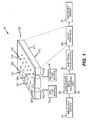
- Inkjet printer system 10 includes an image data source 12, which provides data signals that are interpreted by a controller 14 as being commands to eject drops.
- Controller 14 includes an image processing unit 15 for rendering images for printing, and outputs signals to an electrical pulse source 16 of electrical energy pulses that are inputted to an inkjet printhead 100, which includes at least one inkjet printhead die 110.
- Nozzles 121 in the first nozzle array 120 have a larger opening area than nozzles 131 in the second nozzle array 130.
- each of the two nozzle arrays has two staggered rows of nozzles, each row having a nozzle density of 600 per inch.
- ink delivery pathway 122 is in fluid communication with the first nozzle array 120
- ink delivery pathway 132 is in fluid communication with the second nozzle array 130. Portions of ink delivery pathways 122 and 132 are shown in FIG. 1 as openings through printhead die substrate 111.
- One or more inkjet printhead die 110 will be included in inkjet printhead 100, but for greater clarity only one inkjet printhead die 110 is shown in FIG. 1 .
- first fluid source 18 supplies ink to first nozzle array 120 via ink delivery pathway 122
- second fluid source 19 supplies ink to second nozzle array 130 via ink delivery pathway 132.
- distinct fluid sources 18 and 19 are shown, in some applications it may be beneficial to have a single fluid source supplying ink to both the first nozzle array 120 and the second nozzle array 130 via ink delivery pathways 122 and 132 respectively. Also, in some embodiments, fewer than two or more than two nozzle arrays can be included on printhead die 110. Each nozzle array is supplied by a fluid source. In some embodiments, all nozzles on inkjet printhead die 110 can be the same size, rather than having multiple sized nozzles on inkjet printhead die 110.
- Drop forming mechanisms can be of a variety of types, some of which include a heating element to vaporize a portion of ink and thereby cause ejection of a droplet, or a piezoelectric transducer to constrict the volume of a fluid chamber and thereby cause ejection, or an actuator which is made to move (for example, by heating a bi-layer element) and thereby cause ejection.
- electrical pulses from electrical pulse source 16 are sent to the various drop ejectors according to the desired deposition pattern. In the example of FIG.
- droplets 181 ejected from the first nozzle array 120 are larger than droplets 182 ejected from the second nozzle array 130, due to the larger nozzle opening area.
- droplets 181 ejected from the first nozzle array 120 are larger than droplets 182 ejected from the second nozzle array 130, due to the larger nozzle opening area.
- drop forming mechanisms (not shown) associated respectively with nozzle arrays 120 and 130 are also sized differently in order to optimize the drop ejection process for the different sized drops.
- droplets of ink are deposited on a recording medium 20.
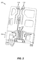
- FIG. 2 shows a bottom perspective view of a printhead frame 250, which is an example of an inkjet printhead 100.
- Printhead frame 250 includes two printhead die 251 (similar to printhead die 110 in FIG. 1 ), each printhead die 251 containing two nozzle arrays 253, so that printhead frame 250 contains four nozzle arrays 253 altogether.
- the four nozzle arrays 253 in this example can each be connected to separate ink sources (not shown in FIG. 2 ); such as cyan, magenta, yellow, and black.
- Each of the four nozzle arrays 253 is disposed along nozzle array direction 254, and the length of each nozzle array along the nozzle array direction 254 is typically on the order of 1 inch or less.
- Typical lengths of recording media are 6 inches for photographic prints (4 inches by 6 inches) or 11 inches for paper (8.5 by 11 inches).
- a number of swaths are successively printed while moving printhead frame 250 across the recording medium 20.
- the recording medium 20 is advanced along a media advance direction that is substantially parallel to nozzle array direction 254.
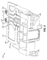
- FIG. 3 shows a front perspective view of a printhead frame 250 including holding receptacle 210 for ink tanks (not shown in FIG. 3 ) according to an embodiment of the invention.
- FIGS. 4-6 show side perspective, rear perspective and top perspective views of the printhead frame 250 of FIG. 3 .
- Holding receptacle 210 includes a first part 211 for holding a multichamber ink tank and a second part 212 for holding a single chamber ink tank.
- Holding receptacle 210 has a base surface 214 for supporting the ink tanks.
- Base surface 214 has a first end 215 and a second end 216 that is opposite first end 215.
- Latch 218 is located near the first end 215 of the base surface 214 of first part 211 of holding receptacle 210, and latch 219 is located near the first end 215 of the base surface 214 of second part 212 of holding receptacle 210 for retaining the respective ink tanks.
- Wall 220 is located near the second end 216 of base surface 214 and adjoins base surface 214.
- Wall 220 includes ink inlet ports 224, 226 and 228 corresponding to first part 211 of holding receptacle 210, and also includes ink inlet port 222 corresponding to second part 212 of holding receptacle 210.
- Ink inlet ports 222, 224, 226 and 228 are connected to ink chambers 202, 204, 206 and 208, which are arranged in two rows, as is described in more detail in commonly assigned US Patent Application Serial No. 12/750,752 .
- the ink inlet ports are configured to receive ink from respective ink tanks (not shown in FIG. 3 ).
- the ink inlet ports 222, 224, 226 and 228 include pipes 229 that extend from wall 220 toward the first end 215 of base surface 214 in order to fluidly connect to corresponding ink outlet ports on the ink tanks.
- Partition 230 adjoins both base surface 214 and wall 220, and is located between a portion of first part 211 and a portion of second part 212 of holding receptacle 210.
- First sidewall 232 of holding receptacle 210 also adjoins both base surface 214 and wall 220.
- Second sidewall 234 of holding receptacle 210 is opposite first sidewall 232 and is substantially parallel to it.
- Partition 230 is located between first sidewall 232 and second sidewall 234. Partition 230 adjoins wall 220 between ink inlet port 222 and ink inlet port 224.
- ink inlet port 224 is located close to partition 230 and ink inlet port 228 is located close to first sidewall 232.
- Ink inlet port 222 is more centrally located within second part 212 of holding receptacle 210. As a result, ink inlet port 224 is located closer to partition 230 than ink inlet port 222 is.
- latches 218 and 219 are preferably cantilevered latches that extend from base surface 214.
- Latches 218 and 219 each contain a free end 235 near the first end 215 of base surface 214.
- Latches 218 and 219, base surface 214, and other elements of printhead frame 250 can be integrally formed together, for example by injection molding.
- Cantilevered latches 218 and 219 include a cantilevered arm 236 and a latching member 238 (see FIG. 3 ) that is located near free end 235.
- Cantilevered arm 236 includes a surface 237 that is coplanar or substantially coplanar with base surface 214.
- Latching member 238 includes a latching surface 239 (se FIGS. 3-5 ) that is substantially perpendicular to the base surface 214. In the embodiment shown in FIGS. 2-6 , latching surface 239 is preferably curved. Latching member 238 also includes a pressing member 240 that extends from the latching surface 239 toward the free end 235 of the cantilevered latches 218 and 219. Pressing member 240 includes a pressing surface 241 that is substantially parallel to base surface 214. As shown in FIG. 3 , pressing surface 241 can be textured. In the normal position shown most clearly in FIGS. 3-5 , the pressing surface 241 is located at a first position, corresponding to a latching position, which is above base surface 214. If pressing member 240 of cantilevered latch 218 or 219 is depressed along pressing direction 242, pressing surface 241 can be relocated to a second position, corresponding to an unlatching position, which is below base surface 214.
- the cantilevered arms 236 of latches 218 and 219 include a first portion 243 located near partition 230, such that the first portion 243 of latch 218 is disposed adjacent a first side of partition 230, and the first portion 243 of latch 219 is disposed adjacent a second side of partition 230, where the second side is opposite the first side.
- Cantilevered arms 236 of latches 218 and 219 extend past partition 230, such that second portion 244 of cantilevered latch 218 is adjacent second portion 244 of cantilevered latch 219.
- Latching member 238 of cantilevered latch 218 is located near latching member 238 of cantilevered latch 219.
- latching member 238 of latch 218 is angled away from latching member 238 of latch 219 near their free ends 235. It is preferable that tip end 245 of the latching member 238 of latch 218 be a distance d (see FIG. 5 ) of at least 3 mm away from tip end 245 of the latching member 238 of latch 219.
- the free ends 235 of cantilevered latches 218 and 219 extend past first end 215 of base surface 214 of holding receptacle 210.
- printhead frame 250 also has at least one bearing surface 248 integrally formed together with holding receptacle 210.
- Bearing surface 248 is intended to ride on a carriage guide in the carriage printer, so that printhead frame 250 also serves as the carriage.
- all of the labeled features in FIG. 3 can be integrally formed, for example, in a single injection molding step. This decreases the cost of forming and assembling the printhead and carriage while retaining the required functionality. It can also make the design more compact.
- FIG. 7 shows a perspective side view of a single chamber ink tank 264 in an orientation for loading into second part 212 of holding receptacle 210 of printhead frame 250.
- Single chamber ink tank 264 is described in more detail below. It consists of an ink chamber (not shown) within the interior of body 270, which includes a bottom wall 271, a first end wall 272 including an ink outlet port (not shown in FIG.
- connecting wall 276 is arcuate-shaped and curves inward toward the interior of body 270 in order to form the recess.
- the first end wall 272, second end wall 273, first sidewall 274 and second sidewall 275 are flat or substantially flat.
- connecting wall 276 can include a plurality of flat or substantially flat walls (not shown) to provide the recess.
- Second sidewall 275 extends from first end wall 272 at an angle that is less than obtuse. More preferably, both first sidewall 274 and second sidewall 275 are perpendicular (or substantially perpendicular) to first end wall 272 in order to facilitate inserting single chamber ink tank 264 along insertion direction 246 into second part 212 of holding receptacle 210.
- first sidewall 274 of the ink tank moves along second sidewall 234 of holding receptacle 210, and indented region 265 of single chamber ink tank 264 moves along partition 230 to guide the insertion so that ink inlet port 222 will engage an ink outlet port (not shown) at the first end wall 272 of the ink tank.
- Connecting wall 276 is curved inward to accommodate a finger or thumb so that the user can grasp single chamber ink tank 264 between connecting wall 276 and first sidewall 274. Because of the recess provided by connecting wall 276, latch 219 begins to extend beyond connecting wall 276 as the ink tank is being inserted.
- Latching surface 239 of latching member 238 of latch 219 (see also FIGS. 3-5 , 8 ) is curved to fit against the recessed surface of connecting wall 276.
- the user can release latch 219 so that pressing surface 241 of pressing member 240 is at its normal latching position above base surface 214.
- Latching surface 239 of latch 219 thus engages connecting wall 276 of single chamber ink tank 264 to hold it in place in holding receptacle 210.
- an exterior surface of at least a portion of connecting wall 276 can be textured with a ribbed surface, for example (not shown).
- tip end 245 of latch 219 does not extend past second end wall 273 of single chamber ink tank 264 when the ink tank is installed and the latching member 238 engages connecting wall 276.
- tip end 245 of latch 219 extends past second end wall 273 when the ink tank is installed, but it extends past by less than 3 mm.
- no multichamber ink tank is present in first part 211 of holding receptacle 210.
- FIG. 9 shows the same view as FIG. 8 , but with both the multi-chamber ink tank 262 and the single chamber ink tank 264 inserted and latched into holding receptacle 210.
- Latching surface 238 of latch 218 holds connecting wall 276 of multichamber ink tank 262
- latching surface 238 of latch 219 holds connecting wall 276 of single chamber ink tank 264.
- the features and insertion method described above relative to single chamber ink tank 264 are similar for multi-chamber ink tank 262 and will not be repeated herein.
- the first end walls 272 of both ink tanks face the same direction.
- the ink outlet ports (not shown) on end walls 272 of the ink tanks face end wall 220 (see FIG. 3 ) and the ink inlet ports 222, 224, 226 and 228.
- the single chamber ink tank 264 is placed next to the multichamber ink tank 262 such that the first end walls 272 of the two ink tanks are aligned with each other (as in FIG.
- the connecting wall 276 of the single chamber ink tank 264 is adjacent the connecting wall 276 of the multichamber ink tank 262. Because the connecting walls 276 are curved toward the interior of the respective ink tanks 262 and 264, thus providing recesses, the adjacent recessed connecting walls 276 provide additional room for the user's finger or thumb to latch or unlatch latches 218 and 219 independently.
- the connecting wall 276 of single chamber ink tank 264 mirror-symmetric relative to connecting wall 276 of multichamber ink tank 262, the two ink tanks 262 and 264 making up the ink supply system have a pleasing appearance in addition to contributing to the ease of replacing ink tanks.
- the first length of the first sidewall 274 of single chamber ink tank 264 is substantially equal to the first length of the first sidewall 274 of multichamber ink tank 262
- the second length of the second sidewall 275 of single chamber ink tank 264 is substantially equal to the second length of the second sidewall 275 of multichamber ink tank 262.
- the ink supply system of the two tanks 262 and 264 are volume efficient, simple and sleek in form.
- the recessed connecting walls 276 do not impact the ink holding volume of ink tanks 262 and 264 very much, as the ink chambers (not shown) on the interior of the ink tank body 270 can extend to the interior side of connecting wall 276 and second end wall 273.
- the "handle" is simply first sidewall 274 and connecting wall 276.
- the ink tanks are less expensive to make, are more compact and have a more streamlined appearance.
- Such an ink tank design also allows for a smaller printing envelope and a smaller printer.
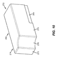
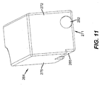
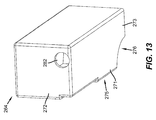
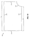
- FIGS. 10-14 The overall appearance of single chamber ink tank 264 is shown in FIGS. 10-14 , and the overall appearance of multichamber ink tank 262 is shown in FIGS. 15-19 .
- FIGS. 10 and 15 are perspective views showing second end wall 273, second sidewall 275 with indented region 265, and connecting wall 276.
- FIGS. 11 and 16 are perspective views showing first end wall 272 with associated ink outlet port(s) and second sidewall 275 with indented region 265.
- Ink outlet port 282 of single chamber ink tank 264 engages with ink inlet port 222 of holding receptacle 210 (see FIGS. 3 and 7 ) when single chamber ink tank 264 is inserted into holding receptacle 210.
- ink outlet ports 284, 286 and 288 engage with ink inlet ports 224, 226 and 228 when multichamber ink tank 262 is inserted into holding receptacle 210.
- Indented region 265 engages with partition 230 of holding receptacle 210 in order to guide the ink tanks into position during insertion.
- Ink outlet ports 282, 284, 286, and 288 are located near the bottom wall 271 of ink tanks 262 and 264 in order to facilitate extracting ink from the ink tanks.
- FIGS. 12 and 17 are perspective views showing first sidewall 274 and first end wall 272 plus associated ink outlet ports. FIGS.
- FIG. 13 and 18 are perspective views showing bottom wall 271 and a portion of the interior of ink tanks 264 and 262 respectively through ink outlet ports 282, 284, 286 and 288.
- ink outlet port 282 of single chamber ink tank 264 it is possible to see the joining of second sidewall 275, connecting wall 276 and a top wall that is opposite bottom wall 271.
- ink outlet port 284 of multichamber ink tank 262 it is possible to see the joining of second sidewall 275, connecting wall 276 and a top wall that is opposite bottom wall 271.
- Ink outlet port 288 of multichamber ink tank 262 it is possible to see the joining of first sidewall 274, connecting wall 276 and a top wall that is opposite bottom wall 271. What is not visible in the view of FIG.
- FIGS. 14 and 19 are top views that clearly show that the length L 1 of first sidewall 274 extending from first end wall 272 to second end wall 273 is longer than length L 2 of second sidewall 275 extending from first end wall 272.
- the curved or arcuate shape of connecting wall 276 forming a recess is also plainly seen in these figures.
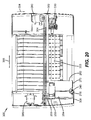
- FIG. 20 shows a top view of a desktop carriage printer 300 according to an embodiment of the present invention. Some of the parts of the printer have been hidden in the view shown in FIG. 20 so that other parts can be more clearly seen.
- Printer 300 has a print region 303 across which carriage 200 is moved back and forth in carriage guide direction 305, while drops are ejected from nozzle array 253 on printhead die 251 (not shown in FIG. 20 ) on printhead frame 250 that is mounted on carriage 200.
- printhead frame 250 is integrally formed with carriage 200 as described above.
- Carriage motor 380 moves belt 384 to move carriage 200 along carriage guide 382.
- Multichamber ink tank 262 and single chamber ink tank 264 are mounted in the holding receptacle of printhead frame 250.
- Latch 218 and its tip end 245 are labeled and shown in proximity to the second end wall 273 of multichamber ink tank 262.
- Printer 300 includes a base 309 on which the printer rests during operation (see FIGS. 21 and 22 ).
- a front wall 308 extends upward from base 309.
- tip end 245 of latch 218 and/or latch 219 is disposed less than 5 mm from an interior surface of the front wall 308 of printer 300.
- second end walls 273 of single chamber ink tank 264 and multichamber ink tank 262 are very near tip ends 245 of their corresponding latches, this means that second end walls 273 are also located close to the interior surface of front wall 308.
- the mounting orientation of printhead frame 250 is rotated relative to the view in FIG. 2 , so that the printhead die 251 are located at the bottom side of printhead frame 250, the droplets of ink being ejected downward onto the paper or other recording medium (not shown) in print region 303.
- Paper advance motor 386 is shown but the various rollers that move the paper along media advance direction 304 are not shown in FIG. 20 .
- Maintenance station 330 is provided for wiping and capping the nozzle face.
- FIGS. 21 and 22 more clearly show front wall 308 of printer 300 and a doorway 310 through which the ink tanks 262 and 264 can be accessed for horizontal installation and removal.
- Printer 300 also includes a top surface (not shown), but the user can reach through doorway 310.
- Doorway 310 can consist of an opening as shown in FIGS. 21 and 22 , or it can also optionally include a door (not shown) that the user can open in order to access the ink tanks 262 and 264.
- the carriage 200 is moved along carriage guide 382 until the ink tanks are located next to doorway 310.
- the user reaches through doorway 310 and releases the latch corresponding to the ink tank and grasps an end of the ink tank at the recessed connecting wall.
- the ink tank is then removed horizontally through the doorway 310.
- a replacement ink tank can then be inserted horizontally through doorway 310.
- the user can slide the replacement ink tank horizontally into the holding receptacle.
- the latching member can be released so that it latches against the connecting wall 276 of the ink tank.
Landscapes
- Ink Jet (AREA)
Claims (15)
- Tintenstrahldrucker, aufweisend:eine Schlittenführung (382) mit einer Schlittenführungsrichtung (305), eine Tintenstrahl-Düsenanordnung (120, 130, 253), die entlang der Schlittenführungsrichtung (305) vor und zurück bewegbar ist;einen Tintentank (262, 264) zum Bereitstellen von Tinte für die Tinten-strahl-Düsenanordnung, wobei der Tintentank austauschbar mit der Tintenstrahl-Düsenanordnung verbindbar ist;eine Aufnahme (210) für mindestens einen Tintentank in einem Tintenstrahldrucker, wobei die Aufnahme folgendes aufweist:eine Grundfläche (214) zum Tragen des Tintentanks, wobei die Grundfläche ein erstes Ende (215) und ein zweites (216) Ende umfasst, welches entgegengesetzt zum ersten Ende liegt;eine Verriegelung (218, 219), die am ersten Ende (215) der Grundfläche angeordnet ist, um den Tintentank in der Aufnahme zu halten; undeine Wand (220), die einen Tinteneinlassanschluss (222, 224, 226, 228) umfasst, der ausgebildet ist, um Tinte vom Tintentank aufzunehmen, wobei die Wand an das zweite Ende (216) der Grundfläche angrenzt.
- Tintenstrahldrucker gemäß Anspruch 1, wobei die Verriegelung (218, 219) eine auslegerartige Verriegelung ist, die sich von der Grundfläche der Aufnahme erstreckt, und ein freies Ende (235) umfasst, welches benachbart zum ersten Ende der Grundfläche ist.
- Tintenstrahldrucker gemäß Anspruch 2, wobei die auslegerartige Verriegelung (218, 219) ferner einen Auslegerarm (236) und ein Verriegelungsglied (238) umfasst, wobei das Verriegelungsglied benachbart zum freien Ende (235) angeordnet ist und eine Verriegelungs-fläche (239) umfasst.
- Tintenstrahldrucker gemäß Anspruch 3, wobei die Verriegelungsfläche (239) des Verriegelungsgliedes (238) im Wesentlichen rechtwinklig zur Grundfläche (214) der Aufnahme verläuft.
- Tintenstrahldrucker gemäß Anspruch 3, wobei ein Abschnitt der Verriegelungsfläche des Verriegelungsgliedes (238) gebogen ist.
- Tintenstrahldrucker gemäß Anspruch 1, wobei der Tintentank ferner folgendes aufweist:(i) eine erste Endwand (272), die einen Tintenauslassanschluss aufweist;(ii) eine zweite Endwand (273) entgegengesetzt zur ersten Stirnwand;(iii) eine erste Seitenwand (274), die sich über eine erste Länge von der ersten Endwand zur zweiten Endwand erstreckt;(iv) eine zweite Seitenwand (275), die sich über eine zweite Länge von der ersten Endwand erstreckt, wobei die zweite Länge kleiner ist als die erste Länge; und(v) eine Verbindungswand (276), die eine Ausnehmung bildet und die zweite Endwand mit der zweiten Seitenwand verbindet.
- Tintenstrahldrucker gemäß Anspruch 6, wobei das Verriegelungsglied der Aufnahme (210) eine Verriegelungsfläche (239) und ein Spitzenende (245) umfasst, wobei das Spitzenende des Verriegelungsgliedes sich nicht über die zweite Endwand des Tintentanks hinaus erstreckt, wenn die Verriegelungsfläche in Eingriff mit der Verbindungswand des Tintentanks steht.
- Tintenstrahldrucker gemäß Anspruch 1, ferner aufweisend:eine Basis (309), auf der der Drucker während des Betriebs ruht; undeine vordere Wand (308), die sich von der Basis erstreckt, wobei die vordere Wand einen Zugang für den Zugriff auf den Tintentank umfasst.
- Tintenstrahldrucker gemäß Anspruch 2, wobei die Tintenstrahl-Düsenanordnung eine erste Tintenstrahl-Düsenanordnung (120) ist, der Tintentank (262, 264) ein erster Tintentank ist, die auslegerartige Verriegelung (218, 219) eine erste auslegerartige Verrieglung ist und der Tinteneinlassanschluss (222, 224, 226, 228) ein erster Tinteneinlassanschluss ist, wobei der Tintenstrahldrucker ferner folgendes aufweist:eine zweite Tintenstrahl-Düsenanordnung (130), die entlang der Schlittenführungsrichtung vor und zurück bewegbar ist;einen zweiten Tintentank zum Bereitstellen von Tinte für die zweite Tintenstrahl-Düsenanordnung;eine zweite auslegerartige Verriegelung, die sich von der Grundfläche der Aufnahme erstreckt und ein Verriegelungsglied umfasst; undeinen zweiten Tinteneinlassanschluss, der an der Wand der Aufnahme vorgesehen ist, wobei der zweite Tinteneinlassanschluss ausgebildet ist, um Tinte vom zweiten Tintentank aufzunehmen.
- Tintenstrahldrucker gemäß Anspruch 9, wobei der erste Tintentank (262, 264) folgendes aufweist:eine erste Endwand, welche einen Tintenauslassanschluss umfasst; eine zweite Endwand entgegengesetzt zur ersten Endwand; undeine Verbindungswand, die ausgebildet ist, um in Eingriff mit dem Verriegelungsglied der ersten auslegerartigen Verriegelung zu kommen;und wobei der zweite Tintentank (262, 264) folgendes aufweist:eine erste Endwand, welche einen Tintenauslassanschluss umfasst; undeine zweite Endwand entgegengesetzt zur ersten Endwand; undeine Verbindungswand, welche ausgebildet ist, um in Eingriff mit dem Verriegelungsglied der zweiten auslegerartigen Verriegelung zu kommen.
- Tintenstrahldrucker gemäß Anspruch 10, wobei die Verbindungswand des ersten Tintentanks (262, 264) benachbart zur Verbindungswand des zweiten Tintentanks (262, 264) liegt, wenn das Verriegelungsglied der ersten auslegerartigen Verriegelung in Eingriff mit der Verbindungswand des ersten Tintentanks und das Verriegelungsglied der zweiten auslegerartigen Verriegelung in Eingriff mit der Verbindungswand des zweiten Tintentanks steht.
- Tintenstrahldrucker gemäß Anspruch 11, wobei die Verbindungswand des ersten Tintentanks (262, 264) bezüglich der zweiten Endwand des ersten Tintentanks zurückgesetzt ist und wobei die Verbindungswand des zweiten Tintentanks bezüglich der zweiten Endwand des zweiten Tintentanks (262, 264) zurückgesetzt ist, wodurch ein zurückgesetzter Bereich entsteht für den Zugriff auf das Verriegelungsglied der ersten und zweiten auslegerartigen Verriegelung mittels eines Fingers oder Daumens.
- Tintenstrahldrucker gemäß Anspruch 12, wobei das Verriegelungsglied der ersten auslegerartigen Verriegelung (218, 219) sich in einem Winkel vom Verriegelungsglied der zweiten auslegerartigen Verriegelung (218, 219) weg erstreckt, sodass ein Spitzenende (245) des Verriegelungsgliedes der ersten auslegerartigen Verriegelung mindestens 3 mm von einem benachbarten Spitzenende (245) des Verriegelungsgliedes der zweiten auslegerartigen Verriegelung entfernt ist.
- Tintenstrahldrucker gemäß Anspruch 13, wobei das Verriegelungsglied der ersten auslegerartigen Verriegelung (218, 219) und das Verriegelungsglied der zweiten auslegerartigen Verriegelung (218, 219) unabhängig voneinander niederdrückbar sind, wenn der erste und der zweite Tintentank installiert sind, so dass der erste und der zweite Tintentank unabhängig voneinander von der Aufnahme entriegelt werden können.
- Verfahren zum Austauschen eines ersten Tintentanks gegen einen Austauschtintentank (262, 264) in einem Tintenstrahldrucker gemäß den Ansprüchen 1 bis 14, wobei der Drucker in einer vorderen Wand (308) einen Zugang (310) hat, wobei das Verfahren die folgenden Schritte aufweist:Versehen einer Verriegelung, die mittels eines Fingers und/oder Daumens gelöst wird;Erfassen eines Endes des ersten Tintentanks an einer Ausnehmung, horizontales Entnehmen des ersten Tintentanks (262, 264) durch den Zugang in der vorderen Wand;horizontales Einsetzen des Austauschtintentanks;Schieben des Austauschtintentanks in die Aufnahme, während das Verriegelungsglied niedergedrückt wird; undFreigeben des Verriegelungsgliedes.
Applications Claiming Priority (2)
| Application Number | Priority Date | Filing Date | Title |
|---|---|---|---|
| US12/750,738 US8317300B2 (en) | 2010-03-31 | 2010-03-31 | Inkjet printer |
| PCT/US2011/028924 WO2011123260A1 (en) | 2010-03-31 | 2011-03-18 | Inkjet printer |
Publications (2)
| Publication Number | Publication Date |
|---|---|
| EP2552702A1 EP2552702A1 (de) | 2013-02-06 |
| EP2552702B1 true EP2552702B1 (de) | 2015-01-14 |
Family
ID=44023069
Family Applications (1)
| Application Number | Title | Priority Date | Filing Date |
|---|---|---|---|
| EP11710643.5A Not-in-force EP2552702B1 (de) | 2010-03-31 | 2011-03-18 | Tintenstrahldrucker |
Country Status (5)
| Country | Link |
|---|---|
| US (1) | US8317300B2 (de) |
| EP (1) | EP2552702B1 (de) |
| CN (1) | CN102821962A (de) |
| BR (1) | BR112012021939A2 (de) |
| WO (1) | WO2011123260A1 (de) |
Families Citing this family (2)
| Publication number | Priority date | Publication date | Assignee | Title |
|---|---|---|---|---|
| JP5875288B2 (ja) * | 2010-08-30 | 2016-03-02 | キヤノン株式会社 | 液体噴射装置 |
| JP6806487B2 (ja) * | 2016-07-29 | 2021-01-06 | キヤノン株式会社 | 液体吐出ヘッド、液体吐出装置および製造方法 |
Family Cites Families (20)
| Publication number | Priority date | Publication date | Assignee | Title |
|---|---|---|---|---|
| ES2058563T3 (es) | 1988-12-29 | 1994-11-01 | Canon Kk | Cabezal de impresion por chorros de tinta y aparato para la impresion por chorros de tinta. |
| EP0546832B1 (de) | 1991-12-11 | 1998-03-25 | Canon Kabushiki Kaisha | Schlitten für Tintenstrahlaufzeichnungsgerät |
| EP0622235B1 (de) | 1993-04-30 | 1997-07-30 | Hewlett-Packard Company | Kontaktunterlageanordnung auf eine Kunststoffdruckkassette |
| JPH0939265A (ja) * | 1995-07-29 | 1997-02-10 | Seiko Epson Corp | プリンタにおけるインクカートリッヂ並びにその識別装置 |
| GB2315045B (en) * | 1996-07-05 | 1998-11-25 | Seiko Epson Corp | Ink cartridge and loading mechanism for the ink cartridge |
| GB2323817B (en) | 1996-07-05 | 1998-11-25 | Seiko Epson Corp | Ink cartridge and loading mechanism for the ink cartridge |
| JP3295339B2 (ja) * | 1996-08-30 | 2002-06-24 | キヤノン株式会社 | インクタンク、ホルダー、インクジェットカートリッジおよびキャップ |
| US6202454B1 (en) | 1997-05-16 | 2001-03-20 | Tomato Land Display Systems, Inc. | Anti-theft security case |
| US6068371A (en) | 1997-09-22 | 2000-05-30 | Owens-Illinois Closure Inc. | Liquid containment and dispensing device with improved position indicating indicia |
| US6655785B1 (en) * | 1999-08-25 | 2003-12-02 | Xerox Corporation | Print element and method for assembling a print head |
| US6499826B1 (en) | 2000-01-05 | 2002-12-31 | Hewlett-Packard Company | Horizontally loadable carriage for an ink-jet printer |
| US6481829B1 (en) * | 2001-09-18 | 2002-11-19 | Lexmark International, Inc. | Manually actuated carrier latch mechanism |
| JP3624950B2 (ja) * | 2002-11-26 | 2005-03-02 | セイコーエプソン株式会社 | インクカートリッジ |
| US7384124B2 (en) * | 2003-01-17 | 2008-06-10 | Samsung Electronics Co., Ltd. | Carriage for ink cartridge of image forming apparatus |
| US7168799B2 (en) | 2004-06-28 | 2007-01-30 | Lexmark International, Inc. | Release mechanism for facilitating supply cartridge installation and removal |
| US7350902B2 (en) | 2004-11-18 | 2008-04-01 | Eastman Kodak Company | Fluid ejection device nozzle array configuration |
| JP4525620B2 (ja) | 2006-03-07 | 2010-08-18 | ブラザー工業株式会社 | 画像記録装置、多機能装置 |
| US7834776B2 (en) | 2008-02-01 | 2010-11-16 | Lexmark International, Inc. | RFID linking device-based switchable sensor, component with switchable sensor, and system for detecting component unseated |
| JP2010083111A (ja) | 2008-10-02 | 2010-04-15 | Riso Kagaku Corp | インクカートリッジの着脱機構及び着脱制御方法 |
| JP2010228379A (ja) | 2009-03-27 | 2010-10-14 | Brother Ind Ltd | インク供給装置 |
-
2010
- 2010-03-31 US US12/750,738 patent/US8317300B2/en not_active Expired - Fee Related
-
2011
- 2011-03-18 WO PCT/US2011/028924 patent/WO2011123260A1/en not_active Ceased
- 2011-03-18 EP EP11710643.5A patent/EP2552702B1/de not_active Not-in-force
- 2011-03-18 BR BR112012021939A patent/BR112012021939A2/pt not_active Application Discontinuation
- 2011-03-18 CN CN2011800166529A patent/CN102821962A/zh active Pending
Also Published As
| Publication number | Publication date |
|---|---|
| US8317300B2 (en) | 2012-11-27 |
| WO2011123260A1 (en) | 2011-10-06 |
| BR112012021939A2 (pt) | 2016-05-31 |
| CN102821962A (zh) | 2012-12-12 |
| EP2552702A1 (de) | 2013-02-06 |
| US20110242231A1 (en) | 2011-10-06 |
Similar Documents
| Publication | Publication Date | Title |
|---|---|---|
| JP3813208B2 (ja) | インクジェット印刷用のマトリクスペン配列 | |
| CN112895724B (zh) | 液体储存装置和液体填充方法 | |
| US20120133713A1 (en) | Ink tank with flexible wall | |
| US8220902B2 (en) | Printhead with improved ink tank mounting reliability | |
| US20110025786A1 (en) | Ink reservoir with a biasing valve | |
| WO2013162595A1 (en) | Removable guide element | |
| US8220903B2 (en) | Ink tank feature for improved mounting reliability | |
| EP2552702B1 (de) | Tintenstrahldrucker | |
| US8313180B2 (en) | Inkjet ink tank | |
| US8240816B2 (en) | Ink fill port for inkjet ink tank | |
| US8277034B2 (en) | Orientation of air-permeable membrane in inkjet printhead | |
| EP2552704B1 (de) | Tintendurchgänge zur verbindung von einlassöffnungen und kammern | |
| US20110242248A1 (en) | Holding receptacle for inkjet ink tank | |
| US8215751B2 (en) | Carriage with improved print cartridge mounting reliability | |
| US20130286112A1 (en) | Inkjet ink tank for snap-on seal | |
| US20110148996A1 (en) | Method for filling an inkjet ink tank | |
| US8590156B2 (en) | Method for assembling an inkjet printhead | |
| JP7013856B2 (ja) | 液体排出装置 | |
| US8322834B2 (en) | Snap-in die mount assembly for inkjet printhead | |
| US8657426B2 (en) | Seal and seal pulling member for ink tank | |
| US20130286110A1 (en) | Snap-on seal for inkjet ink tank |
Legal Events
| Date | Code | Title | Description |
|---|---|---|---|
| PUAI | Public reference made under article 153(3) epc to a published international application that has entered the european phase |
Free format text: ORIGINAL CODE: 0009012 |
|
| 17P | Request for examination filed |
Effective date: 20120906 |
|
| AK | Designated contracting states |
Kind code of ref document: A1 Designated state(s): AL AT BE BG CH CY CZ DE DK EE ES FI FR GB GR HR HU IE IS IT LI LT LU LV MC MK MT NL NO PL PT RO RS SE SI SK SM TR |
|
| DAX | Request for extension of the european patent (deleted) | ||
| GRAP | Despatch of communication of intention to grant a patent |
Free format text: ORIGINAL CODE: EPIDOSNIGR1 |
|
| INTG | Intention to grant announced |
Effective date: 20140723 |
|
| GRAS | Grant fee paid |
Free format text: ORIGINAL CODE: EPIDOSNIGR3 |
|
| GRAA | (expected) grant |
Free format text: ORIGINAL CODE: 0009210 |
|
| AK | Designated contracting states |
Kind code of ref document: B1 Designated state(s): AL AT BE BG CH CY CZ DE DK EE ES FI FR GB GR HR HU IE IS IT LI LT LU LV MC MK MT NL NO PL PT RO RS SE SI SK SM TR |
|
| REG | Reference to a national code |
Ref country code: GB Ref legal event code: FG4D |
|
| REG | Reference to a national code |
Ref country code: CH Ref legal event code: EP |
|
| REG | Reference to a national code |
Ref country code: IE Ref legal event code: FG4D |
|
| REG | Reference to a national code |
Ref country code: AT Ref legal event code: REF Ref document number: 706806 Country of ref document: AT Kind code of ref document: T Effective date: 20150215 |
|
| REG | Reference to a national code |
Ref country code: DE Ref legal event code: R096 Ref document number: 602011013124 Country of ref document: DE Effective date: 20150226 |
|
| REG | Reference to a national code |
Ref country code: NL Ref legal event code: T3 |
|
| REG | Reference to a national code |
Ref country code: AT Ref legal event code: MK05 Ref document number: 706806 Country of ref document: AT Kind code of ref document: T Effective date: 20150114 |
|
| REG | Reference to a national code |
Ref country code: LT Ref legal event code: MG4D |
|
| PG25 | Lapsed in a contracting state [announced via postgrant information from national office to epo] |
Ref country code: FI Free format text: LAPSE BECAUSE OF FAILURE TO SUBMIT A TRANSLATION OF THE DESCRIPTION OR TO PAY THE FEE WITHIN THE PRESCRIBED TIME-LIMIT Effective date: 20150114 Ref country code: SE Free format text: LAPSE BECAUSE OF FAILURE TO SUBMIT A TRANSLATION OF THE DESCRIPTION OR TO PAY THE FEE WITHIN THE PRESCRIBED TIME-LIMIT Effective date: 20150114 Ref country code: LT Free format text: LAPSE BECAUSE OF FAILURE TO SUBMIT A TRANSLATION OF THE DESCRIPTION OR TO PAY THE FEE WITHIN THE PRESCRIBED TIME-LIMIT Effective date: 20150114 Ref country code: BG Free format text: LAPSE BECAUSE OF FAILURE TO SUBMIT A TRANSLATION OF THE DESCRIPTION OR TO PAY THE FEE WITHIN THE PRESCRIBED TIME-LIMIT Effective date: 20150414 Ref country code: NO Free format text: LAPSE BECAUSE OF FAILURE TO SUBMIT A TRANSLATION OF THE DESCRIPTION OR TO PAY THE FEE WITHIN THE PRESCRIBED TIME-LIMIT Effective date: 20150414 Ref country code: ES Free format text: LAPSE BECAUSE OF FAILURE TO SUBMIT A TRANSLATION OF THE DESCRIPTION OR TO PAY THE FEE WITHIN THE PRESCRIBED TIME-LIMIT Effective date: 20150114 Ref country code: HR Free format text: LAPSE BECAUSE OF FAILURE TO SUBMIT A TRANSLATION OF THE DESCRIPTION OR TO PAY THE FEE WITHIN THE PRESCRIBED TIME-LIMIT Effective date: 20150114 |
|
| PG25 | Lapsed in a contracting state [announced via postgrant information from national office to epo] |
Ref country code: LV Free format text: LAPSE BECAUSE OF FAILURE TO SUBMIT A TRANSLATION OF THE DESCRIPTION OR TO PAY THE FEE WITHIN THE PRESCRIBED TIME-LIMIT Effective date: 20150114 Ref country code: GR Free format text: LAPSE BECAUSE OF FAILURE TO SUBMIT A TRANSLATION OF THE DESCRIPTION OR TO PAY THE FEE WITHIN THE PRESCRIBED TIME-LIMIT Effective date: 20150415 Ref country code: AT Free format text: LAPSE BECAUSE OF FAILURE TO SUBMIT A TRANSLATION OF THE DESCRIPTION OR TO PAY THE FEE WITHIN THE PRESCRIBED TIME-LIMIT Effective date: 20150114 Ref country code: RS Free format text: LAPSE BECAUSE OF FAILURE TO SUBMIT A TRANSLATION OF THE DESCRIPTION OR TO PAY THE FEE WITHIN THE PRESCRIBED TIME-LIMIT Effective date: 20150114 Ref country code: IS Free format text: LAPSE BECAUSE OF FAILURE TO SUBMIT A TRANSLATION OF THE DESCRIPTION OR TO PAY THE FEE WITHIN THE PRESCRIBED TIME-LIMIT Effective date: 20150514 Ref country code: PL Free format text: LAPSE BECAUSE OF FAILURE TO SUBMIT A TRANSLATION OF THE DESCRIPTION OR TO PAY THE FEE WITHIN THE PRESCRIBED TIME-LIMIT Effective date: 20150114 |
|
| REG | Reference to a national code |
Ref country code: DE Ref legal event code: R097 Ref document number: 602011013124 Country of ref document: DE |
|
| PG25 | Lapsed in a contracting state [announced via postgrant information from national office to epo] |
Ref country code: LU Free format text: LAPSE BECAUSE OF FAILURE TO SUBMIT A TRANSLATION OF THE DESCRIPTION OR TO PAY THE FEE WITHIN THE PRESCRIBED TIME-LIMIT Effective date: 20150318 Ref country code: SK Free format text: LAPSE BECAUSE OF FAILURE TO SUBMIT A TRANSLATION OF THE DESCRIPTION OR TO PAY THE FEE WITHIN THE PRESCRIBED TIME-LIMIT Effective date: 20150114 Ref country code: RO Free format text: LAPSE BECAUSE OF FAILURE TO SUBMIT A TRANSLATION OF THE DESCRIPTION OR TO PAY THE FEE WITHIN THE PRESCRIBED TIME-LIMIT Effective date: 20150114 Ref country code: EE Free format text: LAPSE BECAUSE OF FAILURE TO SUBMIT A TRANSLATION OF THE DESCRIPTION OR TO PAY THE FEE WITHIN THE PRESCRIBED TIME-LIMIT Effective date: 20150114 Ref country code: CZ Free format text: LAPSE BECAUSE OF FAILURE TO SUBMIT A TRANSLATION OF THE DESCRIPTION OR TO PAY THE FEE WITHIN THE PRESCRIBED TIME-LIMIT Effective date: 20150114 Ref country code: MC Free format text: LAPSE BECAUSE OF FAILURE TO SUBMIT A TRANSLATION OF THE DESCRIPTION OR TO PAY THE FEE WITHIN THE PRESCRIBED TIME-LIMIT Effective date: 20150114 Ref country code: DK Free format text: LAPSE BECAUSE OF FAILURE TO SUBMIT A TRANSLATION OF THE DESCRIPTION OR TO PAY THE FEE WITHIN THE PRESCRIBED TIME-LIMIT Effective date: 20150114 |
|
| REG | Reference to a national code |
Ref country code: CH Ref legal event code: PL |
|
| PLBE | No opposition filed within time limit |
Free format text: ORIGINAL CODE: 0009261 |
|
| STAA | Information on the status of an ep patent application or granted ep patent |
Free format text: STATUS: NO OPPOSITION FILED WITHIN TIME LIMIT |
|
| 26N | No opposition filed |
Effective date: 20151015 |
|
| PG25 | Lapsed in a contracting state [announced via postgrant information from national office to epo] |
Ref country code: IT Free format text: LAPSE BECAUSE OF FAILURE TO SUBMIT A TRANSLATION OF THE DESCRIPTION OR TO PAY THE FEE WITHIN THE PRESCRIBED TIME-LIMIT Effective date: 20150114 |
|
| REG | Reference to a national code |
Ref country code: FR Ref legal event code: ST Effective date: 20151130 |
|
| REG | Reference to a national code |
Ref country code: IE Ref legal event code: MM4A |
|
| PG25 | Lapsed in a contracting state [announced via postgrant information from national office to epo] |
Ref country code: IE Free format text: LAPSE BECAUSE OF NON-PAYMENT OF DUE FEES Effective date: 20150318 Ref country code: CH Free format text: LAPSE BECAUSE OF NON-PAYMENT OF DUE FEES Effective date: 20150331 Ref country code: LI Free format text: LAPSE BECAUSE OF NON-PAYMENT OF DUE FEES Effective date: 20150331 |
|
| PG25 | Lapsed in a contracting state [announced via postgrant information from national office to epo] |
Ref country code: FR Free format text: LAPSE BECAUSE OF NON-PAYMENT OF DUE FEES Effective date: 20150331 Ref country code: SI Free format text: LAPSE BECAUSE OF FAILURE TO SUBMIT A TRANSLATION OF THE DESCRIPTION OR TO PAY THE FEE WITHIN THE PRESCRIBED TIME-LIMIT Effective date: 20150114 |
|
| PG25 | Lapsed in a contracting state [announced via postgrant information from national office to epo] |
Ref country code: BE Free format text: LAPSE BECAUSE OF FAILURE TO SUBMIT A TRANSLATION OF THE DESCRIPTION OR TO PAY THE FEE WITHIN THE PRESCRIBED TIME-LIMIT Effective date: 20150114 |
|
| PG25 | Lapsed in a contracting state [announced via postgrant information from national office to epo] |
Ref country code: MT Free format text: LAPSE BECAUSE OF FAILURE TO SUBMIT A TRANSLATION OF THE DESCRIPTION OR TO PAY THE FEE WITHIN THE PRESCRIBED TIME-LIMIT Effective date: 20150114 |
|
| PG25 | Lapsed in a contracting state [announced via postgrant information from national office to epo] |
Ref country code: SM Free format text: LAPSE BECAUSE OF FAILURE TO SUBMIT A TRANSLATION OF THE DESCRIPTION OR TO PAY THE FEE WITHIN THE PRESCRIBED TIME-LIMIT Effective date: 20150114 Ref country code: HU Free format text: LAPSE BECAUSE OF FAILURE TO SUBMIT A TRANSLATION OF THE DESCRIPTION OR TO PAY THE FEE WITHIN THE PRESCRIBED TIME-LIMIT; INVALID AB INITIO Effective date: 20110318 |
|
| PG25 | Lapsed in a contracting state [announced via postgrant information from national office to epo] |
Ref country code: CY Free format text: LAPSE BECAUSE OF FAILURE TO SUBMIT A TRANSLATION OF THE DESCRIPTION OR TO PAY THE FEE WITHIN THE PRESCRIBED TIME-LIMIT Effective date: 20150114 |
|
| PG25 | Lapsed in a contracting state [announced via postgrant information from national office to epo] |
Ref country code: PT Free format text: LAPSE BECAUSE OF FAILURE TO SUBMIT A TRANSLATION OF THE DESCRIPTION OR TO PAY THE FEE WITHIN THE PRESCRIBED TIME-LIMIT Effective date: 20150514 |
|
| PG25 | Lapsed in a contracting state [announced via postgrant information from national office to epo] |
Ref country code: TR Free format text: LAPSE BECAUSE OF FAILURE TO SUBMIT A TRANSLATION OF THE DESCRIPTION OR TO PAY THE FEE WITHIN THE PRESCRIBED TIME-LIMIT Effective date: 20150114 |
|
| PGFP | Annual fee paid to national office [announced via postgrant information from national office to epo] |
Ref country code: DE Payment date: 20180308 Year of fee payment: 8 Ref country code: GB Payment date: 20180223 Year of fee payment: 8 Ref country code: NL Payment date: 20180312 Year of fee payment: 8 |
|
| PG25 | Lapsed in a contracting state [announced via postgrant information from national office to epo] |
Ref country code: MK Free format text: LAPSE BECAUSE OF FAILURE TO SUBMIT A TRANSLATION OF THE DESCRIPTION OR TO PAY THE FEE WITHIN THE PRESCRIBED TIME-LIMIT Effective date: 20150114 |
|
| PG25 | Lapsed in a contracting state [announced via postgrant information from national office to epo] |
Ref country code: AL Free format text: LAPSE BECAUSE OF FAILURE TO SUBMIT A TRANSLATION OF THE DESCRIPTION OR TO PAY THE FEE WITHIN THE PRESCRIBED TIME-LIMIT Effective date: 20150114 |
|
| REG | Reference to a national code |
Ref country code: DE Ref legal event code: R119 Ref document number: 602011013124 Country of ref document: DE |
|
| REG | Reference to a national code |
Ref country code: NL Ref legal event code: MM Effective date: 20190401 |
|
| GBPC | Gb: european patent ceased through non-payment of renewal fee |
Effective date: 20190318 |
|
| PG25 | Lapsed in a contracting state [announced via postgrant information from national office to epo] |
Ref country code: NL Free format text: LAPSE BECAUSE OF NON-PAYMENT OF DUE FEES Effective date: 20190401 Ref country code: DE Free format text: LAPSE BECAUSE OF NON-PAYMENT OF DUE FEES Effective date: 20191001 Ref country code: GB Free format text: LAPSE BECAUSE OF NON-PAYMENT OF DUE FEES Effective date: 20190318 |