EP2551970A2 - Audio Buchse und dazu gehörigendes Gerät - Google Patents
Audio Buchse und dazu gehörigendes Gerät Download PDFInfo
- Publication number
- EP2551970A2 EP2551970A2 EP20120005460 EP12005460A EP2551970A2 EP 2551970 A2 EP2551970 A2 EP 2551970A2 EP 20120005460 EP20120005460 EP 20120005460 EP 12005460 A EP12005460 A EP 12005460A EP 2551970 A2 EP2551970 A2 EP 2551970A2
- Authority
- EP
- European Patent Office
- Prior art keywords
- elastic terminal
- rotating portion
- audio jack
- extending portion
- pin
- Prior art date
- Legal status (The legal status is an assumption and is not a legal conclusion. Google has not performed a legal analysis and makes no representation as to the accuracy of the status listed.)
- Withdrawn
Links
- 238000003780 insertion Methods 0.000 abstract description 8
- 230000037431 insertion Effects 0.000 abstract description 8
- 238000010586 diagram Methods 0.000 description 21
- 230000004308 accommodation Effects 0.000 description 12
- 238000004891 communication Methods 0.000 description 4
- 238000001514 detection method Methods 0.000 description 4
- 238000004519 manufacturing process Methods 0.000 description 3
- 238000012986 modification Methods 0.000 description 3
- 230000004048 modification Effects 0.000 description 3
- 238000005452 bending Methods 0.000 description 2
- 230000001413 cellular effect Effects 0.000 description 1
- 238000010276 construction Methods 0.000 description 1
- 230000007547 defect Effects 0.000 description 1
- 230000001419 dependent effect Effects 0.000 description 1
- 230000000694 effects Effects 0.000 description 1
- 239000000203 mixture Substances 0.000 description 1
Images



Classifications
-
- H—ELECTRICITY
- H01—ELECTRIC ELEMENTS
- H01R—ELECTRICALLY-CONDUCTIVE CONNECTIONS; STRUCTURAL ASSOCIATIONS OF A PLURALITY OF MUTUALLY-INSULATED ELECTRICAL CONNECTING ELEMENTS; COUPLING DEVICES; CURRENT COLLECTORS
- H01R27/00—Coupling parts adapted for co-operation with two or more dissimilar counterparts
-
- H—ELECTRICITY
- H01—ELECTRIC ELEMENTS
- H01R—ELECTRICALLY-CONDUCTIVE CONNECTIONS; STRUCTURAL ASSOCIATIONS OF A PLURALITY OF MUTUALLY-INSULATED ELECTRICAL CONNECTING ELEMENTS; COUPLING DEVICES; CURRENT COLLECTORS
- H01R29/00—Coupling parts for selective co-operation with a counterpart in different ways to establish different circuits, e.g. for voltage selection, for series-parallel selection, programmable connectors
-
- H—ELECTRICITY
- H01—ELECTRIC ELEMENTS
- H01R—ELECTRICALLY-CONDUCTIVE CONNECTIONS; STRUCTURAL ASSOCIATIONS OF A PLURALITY OF MUTUALLY-INSULATED ELECTRICAL CONNECTING ELEMENTS; COUPLING DEVICES; CURRENT COLLECTORS
- H01R2107/00—Four or more poles
-
- H—ELECTRICITY
- H01—ELECTRIC ELEMENTS
- H01R—ELECTRICALLY-CONDUCTIVE CONNECTIONS; STRUCTURAL ASSOCIATIONS OF A PLURALITY OF MUTUALLY-INSULATED ELECTRICAL CONNECTING ELEMENTS; COUPLING DEVICES; CURRENT COLLECTORS
- H01R24/00—Two-part coupling devices, or either of their cooperating parts, characterised by their overall structure
- H01R24/58—Contacts spaced along longitudinal axis of engagement
Definitions
- the present invention relates to an audio jack of an electronic apparatus, and in particular to an audio jack adapted to pins of different specifications and electronic apparatus containing the same.
- An electronic apparatus with an audio output such as a computer, a walkman, a mobile phone, PDA (Personal Digital Assistant), an MP3 (Moving Picture Experts Group Audio Layer III) and an MP4 (Moving Picture Experts Group Audio Layer IV), etc.
- an audio jack available for connecting an earphone or an external speaker to facilitate a user to select use of an earphone for listening or use of a speaker to enlarge the audio range.
- a 3.5 mm earphone interface is widely used in the design of audio jacks of various electronic apparatuses.
- different industries have different definitions of the pins of the plugs of earphones.
- the audio jacks of electronic apparatuses should be designed differently to be adapted for the earphone plugs of the specifications of different industries and accordingly, the PCBs (Printed Circuit Boards) of these electronic apparatuses should be designed differently.
- Fig. 1a is a schematic diagram of the pin definition of an earphone plug in conformity with CTIA (Cellular Telecommunications & Internet Association) specification.
- CTIA Cellular Telecommunications & Internet Association
- the earphone plug 100 starts from an insertion end, and has an audio left pin 111, an audio right pin 112, a GND pin 113 and an MIC pin 114, respectively. It can be seen that the innermost pin of the earphone plug in conformity with the CTIA specification is the MIC pin.
- Fig. 1b is a schematic diagram of the pin definition of an earphone plug 119 in conformity with OMTP (Open Mobile Terminal Platform) specification. As shown in Fig.
- OMTP Open Mobile Terminal Platform
- the earphone plug 119 starts from an insertion end 120, and has an audio left pin 121, an audio right pin 122, an MIC pin 123 and a GND pin 124, respectively. It can be seen that the innermost pin of the earphone plug in conformity with the OMTP specification is the GND pin. It can be seen from Figs. 1a and 1b , the MIC pin and the GND pin are interchanged for the earphone plugs of different specifications.
- Fig. 2a is a schematic diagram showing a design of an audio jack 210 in conformity with the CTIA specification.
- the audio jack has seven conductive terminals 211-217; wherein the conductive terminal 211 is connected to the MIC pin of the earphone plug, the conductive terminal 212 is connected to the GND pin of the earphone plug, the conductive terminal 216 is connected to the audio right pin of the earphone plug, the conductive terminal 213 is connected to the audio left pin of the earphone plug, and the conductive terminals 214 and 215 are detection terminals.
- each of the conductive terminals is respectively connected to each of the pins of the PCB of the audio jack.
- Fig. 2b is a schematic diagram showing a design of an audio jack 220 in conformity with the OMTP specification.
- the audio jack has seven conductive terminals 221-226 ; wherein the conductive terminal 221 is connected to the GND pin of the earphone plug, the conductive terminal 222 is connected to the MIC pin of the earphone plug, the conductive terminal 226 is connected to the audio right pin of the earphone plug, the conductive terminal 223 is connected to the audio left pin of the earphone plug, and the conductive terminals 224 and 225 are detection terminals.
- each of the conductive terminals is furthermore connected to each of the pins of the PCB 227 of the audio jack, respectively.
- the present invention provides an audio jack as defined in claim 1 and an electronic apparatus as defined in claim 8.
- the dependent claims define preferred embodiments of the invention. It is found by the applicant in the implementation of the present invention that since the definitions of the pins of the earphone plug are different, not only the audio jacks are required to have different designs, but also the corresponding PCBs should have different designs, increasing the cost of manufacture and range of application of the electronic apparatus undoubtedly. The range of application of an electronic apparatus using an audio jack will be wider and the cost will be lower if such an audio jack is provided which is applicable to both the CTIA specification and the OMTP specification.
- the present invention is proposed in view of the above problems of the prior art.
- An aspect of the present invention is to overcome the defect of the existing audio jack that is applicable only to the plug of one specification and to provide an audio jack applicable to plugs of different specifications and an electronic apparatus containing the audio jack.
- the problem to be solved is to increase the range of application of the electronic apparatus on the premise of reducing the cost of the electronic apparatus.
- an audio jack including a hollow insulated housing, wherein the insulated housing includes: a fixed portion and a rotating portion rotating relative to the fixed portion and on which at least two elastic terminals are arranged; and the at least two elastic terminals of the rotating portion being in contact with different pins of a printed circuit board of the audio jack respectively when the rotating portion is in a first position and rotates relative to the fixed portion to a second position.
- an audio jack as stated in the first aspect, wherein, a first elastic terminal and a second elastic terminal are arranged on the rotating portion and have respectively a first extending portion and a second extending portion and a body portion arranged between the first extending portion and the second extending portion; when the rotating portion is at the first position, the first extending portion of the first elastic terminal is in contact with a first pin of the printed circuit board of the audio jack, and the first extending portion of the second elastic terminal is in contact with a second pin of the printed circuit board of the audio jack; and when the rotating portion rotates relative to the fixed portion to the second position, the second extending portion of the second elastic terminal is in contact with the first pin of the printed circuit board of the audio jack, and the second extending portion of the first elastic terminal is in contact with the second pin of the printed circuit board of the audio jack.
- an audio jack as stated in the second aspect, wherein the body portion of the first elastic terminal is arranged at a first side of the rotating portion; the first extending portion of the first elastic terminal is arranged at a second side of the rotating portion perpendicular to the first side, close to the opening and exposed from the rotating portion; the second extending portion of the first elastic terminal is arranged at a third side of the rotating portion perpendicular to the first side, close to the fixed portion and exposed from the rotating portion; wherein the projections of the first extending portion of the first elastic terminal and the second extending portion of the first elastic terminal on the plane of the second side or the third side of the rotating portion are spaced apart at a certain distance.
- an audio jack as stated in the third aspect, wherein the body portion of the second elastic terminal is arranged at a fourth side of the rotating portion in parallel with the first side; the first extending portion of the second elastic terminal is arranged at the second side of the rotating portion perpendicular to the first side, close to the fixed portion and exposed from the rotating portion; the second extending portion of the second elastic terminal is arranged at the third side of the rotating portion perpendicular to the first side, close to the opening and exposed from the rotating portion; wherein the projections of the first extending portion of the second elastic terminal and the second extending portion of the second elastic terminal on the plane of the second side or the third side of the rotating portion are spaced apart at a certain distance.
- an audio jack as stated in the fourth aspect, wherein the projections of the first extending portion of the first elastic terminal and the second extending portion of the second elastic terminal on the plane of the second side or the third side of the rotating portion are overlapped; and the projections of the second extending portion of the first elastic terminal and the first extending portion of the second elastic terminal on the plane of the second side or the third side of the rotating portion are overlapped.
- an audio jack as stated in any of the first to the fifth aspects, wherein the first pin is a GND contact pad, and the second pin is an MIC contact pad; or the first pin is an MIC contact pad, and the second pin is a GND contact pad.
- an audio jack as stated in any of the first to the fifth aspects, wherein the rotating portion and the fixed portion are connected in a nested manner, and a clamp for preventing the rotating portion from sliding relative to the fixed portion is arranged at the position where the rotating portion and the fixed portion are connected.
- an electronic apparatus including an audio jack, and the audio jack including a hollow insulated housing, wherein, the insulated housing includes: a fixed portion and a rotating portion rotating relative to the fixed portion and on which at least two elastic terminals are arranged; and the at least two elastic terminals of the rotating portion being in contact with different pins of a printed circuit board of the audio jack respectively when the rotating portion is in a first position and rotates relative to the fixed portion to a second position.
- a first elastic terminal and a second elastic terminal are arranged on the rotating portion and have respectively a first extending portion and a second extending portion and a body portion arranged between the first extending portion and the second extending portion; when the rotating portion is at the first position, the first extending portion of the first elastic terminal is in contact with a first pin of the printed circuit board of the audio jack, and the first extending portion of the second elastic terminal is in contact with a second pin of the printed circuit board of the audio jack; and when the rotating portion rotates relative to the fixed portion to the second position, the second extending portion of the second elastic terminal is in contact with the first pin of the printed circuit board of the audio jack, and the second extending portion of the first elastic terminal is in contact with the second pin of the printed circuit board of the audio jack.
- an electronic apparatus as stated in the ninth aspect, wherein the body portion of the first elastic terminal is arranged at a first side of the rotating portion; the first extending portion of the first elastic terminal is arranged at a second side of the rotating portion perpendicular to the first side, close to the opening and exposed from the rotating portion; the second extending portion of the first elastic terminal is arranged at a third side of the rotating portion perpendicular to the first side, close to the fixed portion and exposed from the rotating portion; wherein the projections of the first extending portion of the first elastic terminal and the second extending portion of the first elastic terminal on the plane of the second side or the third side of the rotating portion are spaced apart at a certain distance.
- an electronic apparatus as stated in the tenth aspect, wherein the body portion of the second elastic terminal is arranged at a fourth side of the rotating portion in parallel with the first side; the first extending portion of the second elastic terminal is arranged at the second side of the rotating portion perpendicular to the first side, close to the fixed portion and exposed from the rotating portion; the second extending portion of the second elastic terminal is arranged at the third side of the rotating portion perpendicular to the first side, close to the opening and exposed from the rotating portion; wherein the projections of the first extending portion of the second elastic terminal and the second extending portion of the second elastic terminal on the plane of the second side or the third side of the rotating portion are spaced apart at a certain distance.
- an electronic apparatus as stated in the eleventh aspect, wherein the projections of the first extending portion of the first elastic terminal and the second extending portion of the second elastic terminal on the plane of the second side or the third side of the rotating portion are overlapped; and the projections of the second extending portion of the first elastic terminal and the first extending portion of the second elastic terminal on the plane of the second side or the third side of the rotating portion are overlapped.
- an electronic apparatus as stated in any of the eighth to the twelfth aspects, wherein the first pin is a GND contact pad, and the second pin is an MIC contact pad; or the first pin is an MIC contact pad, and the second pin is a GND contact pad.
- an electronic apparatus as stated in any of the eighth to the twelfth aspects, wherein the rotating portion and the fixed portion are connected in a nested manner, and a clamp for preventing the rotating portion from sliding relative to the fixed portion is arranged at the position where the rotating portion and the fixed portion are connected.
- the audio jack and the electronic apparatus containing the audio jack of the present invention are applicable to the insertion of plugs of various specifications, increasing the range of application of the electronic apparatus on the premise of reducing the cost of the electronic apparatus.
- portable radio communication apparatus includes all apparatuses such as mobile telephones, pagers, communicators, electronic organizers, personal digital assistants (PDAs), smartphones, portable communication devices or the like.
- PDAs personal digital assistants
- embodiments of the invention are described primarily in the context of a portable electronic device in the form of a mobile telephone (also referred to as "mobile phone").
- a mobile telephone also referred to as "mobile phone”
- the invention is not limited to the context of a mobile telephone and may relate to any type of appropriate electronic apparatus having the function of photographing and sound recording.
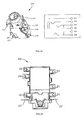
- Fig. 3 illustrates a schematic diagram of the structure of an audio jack 30 according to an embodiment of the present invention.
- the audio jack is for the insertion of a plug, and the plug may be an earphone plug, or may be a speaker plug.
- the audio jack includes a hollow insulated housing 31 having an opening 311, with an accommodation space 311s being formed within the insulated housing 31 for accommodating a plug inserted from the opening 311.
- a plurality of elastic terminals (not shown in this figure) are arranged on the insulated housing 31.
- the insulated housing 31 includes a rotating portion 312 and a fixed portion 313 connected to the rotating portion 312, and the rotating portion 312 may rotate relative to the fixed portion 313.
- the rotating portion 312 and the fixed portion 313 are connected in a nested manner and hence, the rotating portion 312 may rotate free relative to the fixed portion 313.
- the manner of the connection of the rotating portion 312 and the fixed portion 313 is not limited, as long as the rotating portion 312 may rotate free relative to the fixed portion 313, which are covered by the protection scope of the present invention.
- a clamp structure may be arranged at the position where the rotating portion 312 and the fixed portion 313 are connected, so as to prevent the rotating portion 312 from sliding relative to the fixed portion 313.
- the rotating portion 312 may be fixed by the clamp structure, so as to prevent the rotating portion 312 from rotating overmuch, affecting the use of the audio jack.
- the insulated housing includes: a fixed portion 313 and a rotating portion 312 rotating relative to the fixed portion and on which at least two elastic terminals (not shown in this drawing figure) are arranged.
- the at least two elastic terminals of the rotating portion are in contact with different pins of a printed circuit board of the audio jack when the rotating portion is in a first position, and rotate relative to the fixed portion to a second position.
- two of the plurality of elastic terminals are arranged at the rotating portion 312, and other elastic terminals of the plurality of elastic terminals are arranged at the fixed portion 313.
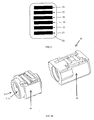
- Fig. 4 illustrates an exploded view of an audio jack 30 according to an embodiment of the present invention.
- Fig. 4 illustrates the top of the audio jack in a default state.
- Fig. 5 illustrates a schematic diagram of a pin arrangement (or terminals arrangement) of a printed circuit board 50 of an audio jack 30 according to an embodiment of the present invention. Reference is made to Figs. 4 and 5 .
- the printed circuit board 50 of the audio jack 30 of this embodiment includes a first pin (or terminal) 51, a second pin 52, a third pin 53, a fourth pin 54, a fifth pin 55 and a sixth pin 56.
- the first pin 51 is a GND contact pad
- the second pin 52 is an MIC contact pad
- the third pin 53 is a speaking right (SPKR) pin contact pad
- the fourth pin 54 and the fifth pin 55 are insertion detection pin contact pads
- the sixth pin 56 is a speaking left (SPKL) pin contact pad.
- the first pin 51 is an MIC contact pad
- the second pin 52 is a GND contact pad
- other pins are unchanged.
- the printed circuit board of the audio jack of this embodiment is arranged at the bottom of the audio jack, and its pins are in contact with the elastic terminals of the audio jack, thereby carrying out the function of the audio jack.
- a first elastic terminal 41 and a second elastic terminal 42 are arranged at the rotating portion 312 and have respectively a first extending portion 411, 421 and a second extending portion 412, 422 and a body portion 413, 423 arranged between the first extending portion 411, 421 and the second extending portion 412, 422.
- the rotating portion 312 is in a first position, and the first extending portion 411 of the first elastic terminal 41 is positioned on the bottom of the audio jack and is close to the opening 311, thereby contacting the first pin 51 of the printed circuit board of the audio jack; and the first extending portion 421 of the second elastic terminal 42 is positioned on the bottom of the audio jack and is close to the fixed portion 313, thereby contacting the second pin 52 of the printed circuit board 50 of the audio jack.
- the rotating portion 312 rotates relative to the fixed portion 313 to a second position, for example, rotates 180 degrees
- the relative position of the two extending portions of the first elastic terminal 41 and the second elastic terminal 42 are changed.
- the first extending portion 411 of the first elastic terminal 41 moves to the top from the bottom of the audio jack and is out of contact with the printed circuit board 50
- the first extending portion 421 of the second elastic terminal 42 moves to the top from the bottom of the audio jack and may be in contact with the printed circuit board.
- the second extending portion 412 of the first elastic terminal 41 is close to the fixed portion, it may be in contact with the second pin 52 of the printed circuit board 50.
- the second extending portion 422 of the second elastic terminal 42 moves to the top from the bottom of the audio jack and may be in contact with the printed circuit board. Since the second extending portion 422 of the second elastic terminal 42 is close to the opening 311, it may be in contact with the first pin 51 of the printed circuit board.
- the rotating portion 312 is in the first position or rotates relative to the fixed portion 313 to the second position
- the first elastic terminal 41 is in contact with the first pin of the plug
- the second elastic terminal 42 is in contact with the second pin of the plug.
- the first pin is the innermost pin of the plug
- the second pin is the pin next to the first pin.
- a first pin contact portion 4131 is arranged on the body portion 413 of the first elastic terminal 41, which extends into the accommodation space 311s of the insulated housing through a hole provided in a first side of the rotating portion 312, and is in contact with the first pin of the plug when the plug is inserted into the accommodation space of the insulated housing through the opening 311.
- a second pin contact portion (not shown) is arranged on the body portion 423 of the second elastic terminal 42, which extends into the accommodation space 311s of the insulated housing through a hole provided in a fourth side of the rotating portion 312, and is in contact with the second pin of the plug when the plug is inserted into the accommodation space of the insulated housing through the opening 311.
- the first pin contact portion 4131 arranged on the body portion 413 of the first elastic terminal 41 is close to the opening 311, and the second pin contact portion arranged on the body portion 423 of the second elastic terminal 42 is close to the fixed portion 313.
- the first side and the fourth side of the rotating portion 312 are opposite sides of the rotating portion 312. In an embodiment, the first side and the fourth side of the rotating portion 312 are arranged in parallel.
- other elastic terminals are arranged on the fixed portion 313, such as the elastic terminal 43 in contact with the speaking left pin of the plug and the speaking left pin contact pad on the printed circuit board, the elastic terminal 44 in contact with the speaking right pin of the plug and the speaking right pin contact pad on the printed circuit board, and the elastic terminals in contact with the insertion detection pin contact pads on the printed circuit board, etc.
- the positions and structures of the elastic terminals arranged on the fixed portion 313 may be the same as those of the elastic terminals on an existing audio jack, which shall not be described any further.
- the audio jack of this embodiment may be applicable to plugs of two different specifications, with no need of changing the printed circuit board.
- first elastic terminal 41 and the second elastic terminal 42 will be described below in detail with reference to Fig. 4 .
- the body portion 413 of the first elastic terminal 41 is arranged at a first side of the rotating portion 312.
- the first extending portion 411 of the first elastic terminal 41 is arranged at a second side of the rotating portion 312 perpendicular to the first side, close to the opening 311, and exposed from the rotating portion 312.
- the second extending portion 412 of the first elastic terminal 41 is arranged at a third side of the rotating portion 312 perpendicular to the first side, close to the fixed portion 313 and exposed from the rotating portion 312.
- the projections of the first extending portion 411 of the first elastic terminal 41 and the second extending portion 412 of the first elastic terminal 41 on the plane of the second side or the third side of the rotating portion 312 are spaced apart at a certain distance.
- the first extending portion 411 and the second extending portion 412 of the first elastic terminal 41 are respectively positioned on an upper face and a lower face, i.e. the second side and the third side, of the rotating portion 312, and the first extending portion 411 and the second extending portion 412 are arranged in a staggered manner, that is, their projections on the upper face and the lower face are spaced apart at a certain distance.
- the first extending portion 411, the second extending portion 412 and the body portion 413 of the first elastic terminal 41 may be formed integrally, or may be otherwise electrically connected.
- the first extending portion 411 and the body portion 413 of the first elastic terminal 41 is formed integrally, while the second extending portion 412 and the body portion 413 of the first elastic terminal 41 is not formed integrally, but are electrically connected when they are inserted into the rotating portion 312.
- the first pin contact portion 4131 arranged on the body portion 413 may be formed by bending an end of the body portion 413 and extending it towards the accommodation space 311s of the insulated housing 31, or may be formed otherwise.
- the body portion 423 of the second elastic terminal 42 is arranged at a fourth side of the rotating portion 312 perpendicular to the first side.
- the first extending portion 421 of the second elastic terminal 42 is arranged at a second side of the rotating portion 312 perpendicular to the first side, close to the fixed portion 313, and exposed from the rotating portion 312.
- the second extending portion 422 of the second elastic terminal 42 is arranged at a third side of the rotating portion 312 perpendicular to the first side, close to the opening 311 and exposed from the rotating portion 312.
- the projections of the first extending portion 421 of the second elastic terminal 42 and the second extending portion 422 of the second elastic terminal 42 on the plane of the second side or the third side of the rotating portion 312 are spaced apart at a certain distance.
- the first extending portion 421 and the second extending portion 422 of the second elastic terminal 42 are respectively positioned on an upper face and a lower face, i.e. the second side and the third side, of the rotating portion 312, and the first extending portion 421 and the second extending portion 422 are arranged in a staggered manner, that is, their projections on the upper face and the lower face are spaced apart at a certain distance.
- the first extending portion 421, the second extending portion 422 and the body portion 423 of the second elastic terminal 42 may be formed integrally, or may be otherwise electrically connected.
- the first extending portion 421 and the body portion 423 of the second elastic terminal 42 are formed integrally, while the second extending portion 422 and the body portion 423 of the second elastic terminal 42 are not formed integrally, but are electrically connected when they are inserted into the rotating portion 312.
- the second pin contact portion arranged on the body portion 423 may be formed by bending an end of the body portion 423 and extending it towards the accommodation space of the insulated housing, or may be formed otherwise.
- the projections of the first extending portion 411 of the first elastic terminal 41 and the second extending portion 422 of the second elastic terminal 42 on the plane of the second side or the third side of the rotating portion 312 are overlapped, and the projections of the second extending portion 412 of the first elastic terminal 41 and the first extending portion 421 of the second elastic terminal 42 on the plane of the second side or the third side of the rotating portion 312 are overlapped.
- the first elastic terminal 41 and the second elastic terminal 42 in a default state, i.e. when the rotating portion 312 is in the first position, as shown in Fig. 4 , the first extending portion 411 of the first elastic terminal 41 is in contact with the first pin 51 of the printed circuit board 50 of the audio jack 30, and the first extending portion 421 of the second elastic terminal 42 is in contact with the second pin 52 of the printed circuit board of the audio jack.
- the rotating portion 312 rotates relative to the fixed portion 313 to the second position, for example, rotates 180 degrees to the second position
- the second extending portion 422 of the second elastic terminal 42 is in contact with the first pin 51 of the printed circuit board 50 of the audio jack 30
- the second extending portion 412 of the first elastic terminal 41 is in contact with the second pin 52 of the printed circuit board of the audio jack. Since the first pin 51 and the second pin 52 of the printed circuit board of the audio jack are fixed, the rotation of the rotating portion 312 is realized, causing the audio jack to support plugs of different specifications. And since the printed circuit board 50 is unchanged, when the audio jack 30 is applied to an electronic apparatus, the range of application of the electronic apparatus is increased on the premise of reducing the cost of the electronic apparatus.
- the audio jack 30 of the embodiments of the present invention will be described below with reference to a schematic diagram of the operational state of the audio jack of the embodiments of the present invention.
- the first pin of the audio jack is a GND pad and the second pin is an MIC pad as an example.
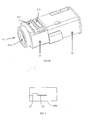
- Figs. 6a and 6b illustrate schematic diagrams of the compositions of the audio jack 30 according to the embodiments of the present invention.
- the insulated housing includes a rotating portion 61 and a fixed portion 62, the rotating portion 61 being rotatable relative to the fixed portion 62.
- the structures of the rotating portion 61 and the fixed portion 62 are identical those shown in Fig. 4 (also described above with reference to reference numerals 312, 313, respectively), which shall not be described any further.
- Fig. 6a illustrates the bottom of the audio jack
- Fig. 6b illustrates the top of the audio jack.
- Fig. 6c illustrates a schematic diagram of the rotating portion 61 and the fixed portion 62 of the audio jack 30 shown in Fig. 6a which are connected.
- a first elastic terminal 611 arranged at the rotating portion 61 is exposed from the rotating portion 61, the exposed portion (the first extending portion of the first elastic terminal 611) being close to the opening and in contact with the GND pad 51 of the printed circuit board 50 of the audio jack 30; and a second elastic terminal 612 arranged at the rotating portion 61 is exposed from the rotating portion 61, the exposed portion (the first extending portion of the second elastic terminal 612) being close to the fixed portion 62 and in contact with the MIC pad 52 of the printed circuit board 50 of the audio jack 30.
- the audio jack is capable of supporting the plug of the OMTP specification.
- Fig. 6d illustrates a schematic diagram of the rotating portion 61 and the fixed portion 62 of the audio jack 30 shown in Fig. 6b which are connected.
- the first elastic terminal 611 arranged at the rotating portion 61 is exposed from the rotating portion 61, the exposed portion (the second extending portion of the first elastic terminal 611) being close to the fixed portion 62; and the second elastic terminal 612 arranged at the rotating portion 61 is exposed from the rotating portion 61, the exposed portion (the second extending portion of the second elastic terminal 612) being close to the opening.
- the first elastic terminal 611 arranged at the rotating portion 61 is exposed from the rotating portion 61, the exposed portion (the second extending portion of the first elastic terminal 611) being close to the fixed portion 62; and the second elastic terminal 612 arranged at the rotating portion 61 is exposed from the rotating portion 61, the exposed portion (the second extending portion of the second elastic terminal 612) being close to the opening.
- the portion of the first elastic terminal 611 exposed from the rotating portion 61 is close to the fixed portion 62, and the portion of the second elastic terminal 612 exposed from the rotating portion 61 is close to the opening. Therefore, when the rotating portion 61 rotates 180 degrees relative to the fixed portion 62 to the position or orientation shown in Fig. 6d , the relative position of the elastic terminal arranged on the fixed portion 62 will not be changed and, similar to what is shown in Fig. 6c , is still in contact with a corresponding pin (terminal) pad of the printed circuit board 50 of the audio jack 30, while the first elastic terminal 611 and the second elastic terminal 612 in contact with the GND pad and the MIC pad of the printed circuit board of the audio jack will be changed.
- the second elastic terminal 612 is in contact with the GND pad of the printed circuit board, and the first elastic terminal 611 is in contact with the MIC pad of the printed circuit board.
- the first elastic terminal 611 of the rotating portion 61 is in contact with the MIC pin of the plug and the MIC pad of the printed circuit board, and the second elastic terminal 612 of the rotating portion 61 is in contact with the GND pin of the plug and the GND pad of the printed circuit board.
- the audio jack is capable of supporting the plug of the CTIA specification.
- the audio jack of the embodiments of the present invention may support plugs of two different specifications, and use one printed circuit board. Hence, not only the cost of manufacture is saved, but also the range of application is increased.
- an electronic apparatus 1000 as is illustrated schematically in Fig. 7 .
- the electronic apparatus includes an audio jack 30 for insertion of a plug.
- the audio jack includes a hollow insulated housing having an opening, an accommodation space being formed within the insulated housing for accommodating the plug inserted from the opening, and a plurality of elastic terminals being arranged on the insulated housing.
- the insulated housing includes a fixed portion and a rotating portion rotating relative to the fixed portion and on which at least two elastic terminals are arranged; the at least two elastic terminals of the rotating portion being in contact with different pins of a printed circuit board 50 of the audio jack 30 respectively when the rotating portion is in a first position and rotates relative to the fixed portion to a second position.
- the rotating portion and the fixed portion are connected in a nested manner.
- a first elastic terminal and second elastic terminal are arranged on the rotating portion and having respectively a first extending portion, a second extending portion and a body portion arranged between the first extending portion and the second extending portion.
- the first extending portion of the first elastic terminal is in contact with a first pin of the printed circuit board of the audio jack, and the first extending portion of the second elastic terminal is in contact with a second pin of the printed circuit board of the audio jack.
- the rotating portion rotates relative to the fixed portion to the second position, the second extending portion of the second elastic terminal is in contact with the first pin of the printed circuit board of the audio jack, and the second extending portion of the first elastic terminal is in contact with the second pin of the printed circuit board of the audio jack.
- the first pin is a GND contact pad
- the second pin is an MIC contact pad
- the first pin is an MIC contact pad
- the second pin is a GND contact pad
- the body portion of the first elastic terminal is arranged at a first side of the rotating portion; the first extending portion of the first elastic terminal is arranged at a second side of the rotating portion perpendicular to the first side, close to the opening and exposed from the rotating portion; the second extending portion of the first elastic terminal is arranged at a third side of the rotating portion perpendicular to the first side, close to the fixed portion and exposed from the rotating portion; wherein the projections of the first extending portion of the first elastic terminal and the second extending portion of the first elastic terminal on the plane of the second side or the third side of the rotating portion are spaced apart at a certain distance.
- the body portion of the second elastic terminal is arranged at a fourth side of the rotating portion in parallel with the first side; the first extending portion of the second elastic terminal is arranged at the second side of the rotating portion perpendicular to the first side, close to the fixed portion and exposed from the rotating portion; the second extending portion of the second elastic terminal is arranged at the third side of the rotating portion perpendicular to the first side, close to the opening and exposed from the rotating portion; wherein the projections of the first extending portion of the second elastic terminal and the second extending portion of the second elastic terminal on the plane of the second side or the third side of the rotating portion are spaced apart at a certain distance.
- the projections of the first extending portion of the first elastic terminal and the second extending portion of the second elastic terminal on the plane of the second side or the third side of the rotating portion are overlapped; and the projections of the second extending portion of the first elastic terminal and the first extending portion of the second elastic terminal on the plane of the second side or the third side of the rotating portion are overlapped.
- the audio jack of the electronic apparatus may be realized by using the audio jack shown in Fig. 4 .
- the contents of the audio jack shown in Fig. 4 are incorporated herein, which shall not be described any further.
- An audio jack capable of supporting plugs of two different specifications is used in the electronic apparatus of the embodiments of the present invention, which realizes the support of plugs of two different specifications, not only saving the cost of manufacture, but also increasing the range of application of the electronic apparatus.
Landscapes
- Coupling Device And Connection With Printed Circuit (AREA)
Applications Claiming Priority (2)
| Application Number | Priority Date | Filing Date | Title |
|---|---|---|---|
| CN2011102141123A CN102904132A (zh) | 2011-07-28 | 2011-07-28 | 一种音频插座及包含该音频插座的电子设备 |
| US13/556,600 US8662937B2 (en) | 2011-07-28 | 2012-07-24 | Audio jack and electronic apparatus containing the same |
Publications (2)
| Publication Number | Publication Date |
|---|---|
| EP2551970A2 true EP2551970A2 (de) | 2013-01-30 |
| EP2551970A3 EP2551970A3 (de) | 2013-02-06 |
Family
ID=46980667
Family Applications (1)
| Application Number | Title | Priority Date | Filing Date |
|---|---|---|---|
| EP20120005460 Withdrawn EP2551970A3 (de) | 2011-07-28 | 2012-07-26 | Audio Buchse und dazu gehörigendes Gerät |
Country Status (1)
| Country | Link |
|---|---|
| EP (1) | EP2551970A3 (de) |
Cited By (1)
| Publication number | Priority date | Publication date | Assignee | Title |
|---|---|---|---|---|
| CN103326168A (zh) * | 2013-05-15 | 2013-09-25 | 惠州Tcl移动通信有限公司 | 一种薄化耳机插座及移动终端 |
Family Cites Families (2)
| Publication number | Priority date | Publication date | Assignee | Title |
|---|---|---|---|---|
| CN101297262A (zh) * | 2005-10-25 | 2008-10-29 | 佩斯微技术有限公司 | 带有适于用户可操作地进行操纵以控制其插口的消费性电子设备 |
| TWM334514U (en) * | 2008-01-04 | 2008-06-11 | Advanced Connectek Inc | Socket connector |
-
2012
- 2012-07-26 EP EP20120005460 patent/EP2551970A3/de not_active Withdrawn
Non-Patent Citations (1)
| Title |
|---|
| None |
Cited By (2)
| Publication number | Priority date | Publication date | Assignee | Title |
|---|---|---|---|---|
| CN103326168A (zh) * | 2013-05-15 | 2013-09-25 | 惠州Tcl移动通信有限公司 | 一种薄化耳机插座及移动终端 |
| CN103326168B (zh) * | 2013-05-15 | 2016-01-27 | 惠州Tcl移动通信有限公司 | 一种薄化耳机插座及移动终端 |
Also Published As
| Publication number | Publication date |
|---|---|
| EP2551970A3 (de) | 2013-02-06 |
Similar Documents
| Publication | Publication Date | Title |
|---|---|---|
| US8662937B2 (en) | Audio jack and electronic apparatus containing the same | |
| CN105898980B (zh) | 用于电子装置的电磁屏蔽结构和电子装置 | |
| KR101394858B1 (ko) | 내장형 안테나들을 갖는 커넥터들 | |
| CN205376880U (zh) | 电连接器 | |
| JP5873798B2 (ja) | 無線端末装置 | |
| JP5565858B2 (ja) | 携帯通信端末 | |
| CN101420076A (zh) | 连接器组件 | |
| EP2961007B1 (de) | Kopfhörerbuchsenanordnung und elektronische ausrüstung | |
| KR20130143339A (ko) | 각도조절 이어잭 모듈 | |
| US8070494B2 (en) | Universal connector and electronic device using the same | |
| CN102474538A (zh) | 便携式无线电装置 | |
| EP2551970A2 (de) | Audio Buchse und dazu gehörigendes Gerät | |
| CN204441445U (zh) | 移动显示终端 | |
| US8251706B2 (en) | Data cable with suction cup and electronic device using the same | |
| KR101092315B1 (ko) | 측면 안테나를 구비한 배터리팩 | |
| KR100678187B1 (ko) | 휴대 단말기의 인쇄회로기판간 연결 케이블 장치 | |
| KR20120069017A (ko) | 전기 커넥터 | |
| CN105824371B (zh) | 一种显示屏组件以及电子终端 | |
| CN205039969U (zh) | 微小电路结构和蓝牙耳机 | |
| CN102740186A (zh) | 音频界面结构与使用该结构的电子装置 | |
| CN204836577U (zh) | Mems麦克风 | |
| KR20090033236A (ko) | 회로 기판의 모서리 상에 노출된 접점을 위한 측면 스위치 | |
| EP2880715B1 (de) | Abdeckung mit einem steckverindergehäuse und mobiles endgerät | |
| CN209517642U (zh) | 一种电路板装置及移动终端 | |
| CN107659680A (zh) | 电路板组件及其屏蔽罩、移动终端 |
Legal Events
| Date | Code | Title | Description |
|---|---|---|---|
| PUAL | Search report despatched |
Free format text: ORIGINAL CODE: 0009013 |
|
| PUAI | Public reference made under article 153(3) epc to a published international application that has entered the european phase |
Free format text: ORIGINAL CODE: 0009012 |
|
| AK | Designated contracting states |
Kind code of ref document: A2 Designated state(s): AL AT BE BG CH CY CZ DE DK EE ES FI FR GB GR HR HU IE IS IT LI LT LU LV MC MK MT NL NO PL PT RO RS SE SI SK SM TR |
|
| AX | Request for extension of the european patent |
Extension state: BA ME |
|
| AK | Designated contracting states |
Kind code of ref document: A3 Designated state(s): AL AT BE BG CH CY CZ DE DK EE ES FI FR GB GR HR HU IE IS IT LI LT LU LV MC MK MT NL NO PL PT RO RS SE SI SK SM TR |
|
| AX | Request for extension of the european patent |
Extension state: BA ME |
|
| RIC1 | Information provided on ipc code assigned before grant |
Ipc: H01R 29/00 20060101ALI20130103BHEP Ipc: H01R 107/00 20060101ALN20130103BHEP Ipc: H01R 27/00 20060101AFI20130103BHEP Ipc: H01R 24/58 20110101ALN20130103BHEP |
|
| RBV | Designated contracting states (corrected) |
Designated state(s): AL AT BE BG CH CY CZ DE DK EE ES FI FR GB GR HR HU IE IS IT LI LT LU LV MC MK MT NL NO PL PT RO RS SE SI SK SM TR |
|
| 17P | Request for examination filed |
Effective date: 20130731 |
|
| 17Q | First examination report despatched |
Effective date: 20150326 |
|
| STAA | Information on the status of an ep patent application or granted ep patent |
Free format text: STATUS: THE APPLICATION IS DEEMED TO BE WITHDRAWN |
|
| 18D | Application deemed to be withdrawn |
Effective date: 20150806 |