EP2551963A1 - Elément de raccordement électrique - Google Patents
Elément de raccordement électrique Download PDFInfo
- Publication number
- EP2551963A1 EP2551963A1 EP11006296A EP11006296A EP2551963A1 EP 2551963 A1 EP2551963 A1 EP 2551963A1 EP 11006296 A EP11006296 A EP 11006296A EP 11006296 A EP11006296 A EP 11006296A EP 2551963 A1 EP2551963 A1 EP 2551963A1
- Authority
- EP
- European Patent Office
- Prior art keywords
- connection element
- fingers
- sheet
- tongue
- electrical connection
- Prior art date
- Legal status (The legal status is an assumption and is not a legal conclusion. Google has not performed a legal analysis and makes no representation as to the accuracy of the status listed.)
- Granted
Links
- 239000004020 conductor Substances 0.000 claims abstract description 5
- 238000003780 insertion Methods 0.000 claims description 32
- 230000037431 insertion Effects 0.000 claims description 32
- 229910052751 metal Inorganic materials 0.000 claims description 16
- 239000002184 metal Substances 0.000 claims description 16
- 238000004519 manufacturing process Methods 0.000 claims description 4
- 230000008878 coupling Effects 0.000 claims description 2
- 238000010168 coupling process Methods 0.000 claims description 2
- 238000005859 coupling reaction Methods 0.000 claims description 2
- 210000002105 tongue Anatomy 0.000 description 65
- 230000013011 mating Effects 0.000 description 9
- 238000005452 bending Methods 0.000 description 3
- 238000002788 crimping Methods 0.000 description 2
- 238000009826 distribution Methods 0.000 description 2
- 238000000034 method Methods 0.000 description 2
- 238000005476 soldering Methods 0.000 description 2
- 238000003466 welding Methods 0.000 description 2
- 229910000838 Al alloy Inorganic materials 0.000 description 1
- RYGMFSIKBFXOCR-UHFFFAOYSA-N Copper Chemical compound [Cu] RYGMFSIKBFXOCR-UHFFFAOYSA-N 0.000 description 1
- 229910000881 Cu alloy Inorganic materials 0.000 description 1
- 230000005540 biological transmission Effects 0.000 description 1
- 239000010949 copper Substances 0.000 description 1
- 230000001419 dependent effect Effects 0.000 description 1
- 238000010438 heat treatment Methods 0.000 description 1
- 230000036316 preload Effects 0.000 description 1
- 238000004080 punching Methods 0.000 description 1
- 230000002459 sustained effect Effects 0.000 description 1
Images


Classifications
-
- H—ELECTRICITY
- H01—ELECTRIC ELEMENTS
- H01R—ELECTRICALLY-CONDUCTIVE CONNECTIONS; STRUCTURAL ASSOCIATIONS OF A PLURALITY OF MUTUALLY-INSULATED ELECTRICAL CONNECTING ELEMENTS; COUPLING DEVICES; CURRENT COLLECTORS
- H01R13/00—Details of coupling devices of the kinds covered by groups H01R12/70 or H01R24/00 - H01R33/00
- H01R13/02—Contact members
- H01R13/28—Contacts for sliding cooperation with identically-shaped contact, e.g. for hermaphroditic coupling devices
-
- H—ELECTRICITY
- H01—ELECTRIC ELEMENTS
- H01R—ELECTRICALLY-CONDUCTIVE CONNECTIONS; STRUCTURAL ASSOCIATIONS OF A PLURALITY OF MUTUALLY-INSULATED ELECTRICAL CONNECTING ELEMENTS; COUPLING DEVICES; CURRENT COLLECTORS
- H01R13/00—Details of coupling devices of the kinds covered by groups H01R12/70 or H01R24/00 - H01R33/00
- H01R13/02—Contact members
- H01R13/193—Means for increasing contact pressure at the end of engagement of coupling part, e.g. zero insertion force or no friction
-
- H—ELECTRICITY
- H01—ELECTRIC ELEMENTS
- H01R—ELECTRICALLY-CONDUCTIVE CONNECTIONS; STRUCTURAL ASSOCIATIONS OF A PLURALITY OF MUTUALLY-INSULATED ELECTRICAL CONNECTING ELEMENTS; COUPLING DEVICES; CURRENT COLLECTORS
- H01R43/00—Apparatus or processes specially adapted for manufacturing, assembling, maintaining, or repairing of line connectors or current collectors or for joining electric conductors
- H01R43/16—Apparatus or processes specially adapted for manufacturing, assembling, maintaining, or repairing of line connectors or current collectors or for joining electric conductors for manufacturing contact members, e.g. by punching and by bending
Definitions
- the present invention relates to an electrical connection element according to the preamble of claim 1, as it is known for example from EP 2 065 982 A1 has become known.
- connection elements In order to be able to produce an electrical connection using such connection elements, two identical connection elements are spaced apart with their front sides facing each other, wherein the two connection elements in each case about 45 ° in a first, against the cantilevered ends of the locking wings pointing direction relative to each other and rotated be brought into contact with each other so that the Deutschengreifungsabête of one electrical connection element with the spokes of the other connection element come into abutment.
- connection elements of a combined plug-and-turn movement must be subjected, wherein the two connection elements are moved toward each other in the axial direction with continued rotational movement and braced against each other.
- connection element Since that in the EP 2 065 982 A1 described connection element must be subjected to a rotational movement to produce an electrical connection, this connection element is not suitable for the production of a pure connector.
- connection element of EP 2 065 982 A1 do not provide multiple side by side on an electrical component, so as to be able to transmit very large currents.
- the invention is therefore based on the object to further develop a generic connection element such that it by a pure Mating process with an identical connection element coupled and is suitable for transmitting large currents.
- connection element with the features of claim 1 and in particular in that the connection element has two freely projecting in the insertion direction of the connection element finger, which extend parallel to the at least one cantilevered tongue in the sheet metal plane, the two freely projecting fingers in the insertion direction form the front end of the connecting element.
- the two freely projecting in the insertion direction of the connecting element fingers thus define between them a gap open at the front end of the connecting element, which is covered by the bent out of the sheet metal plane, cantilevered tongue.
- the fingers of one connection element or the gap formed thereby serve as guides for the tongue of the respective other connection element, whereby a snug fit of two (identical) connection elements to be connected can be ensured.
- the two cantilevered fingers such as the cantilevered tongue extend in the insertion direction of the connecting element while the same form the front end, two 180 ° to each other twisted identical connection elements with the free ends of the cantilevered fingers ahead by a linear insertion movement with each other be brought into engagement, which has the consequence that the metal sheet from which the respective connection element is punched, between the two fingers and the cantilevered tongue of the other connection element is frictionally clamped.
- connection elements can thus be coupled together in the desired manner by a linear plug movement, wherein they are then secured by friction against each other.
- the two freely projecting fingers of each connection element serve as a guide for the other connection element, since during the plugging operation, the cantilevered tongue with its free end protrudes into the slot between the two freely projecting fingers of the other connection element, which passes through the bending out of the tongue of the other connection element from the sheet plane have arisen.
- connection element to have a contacting section for connecting an electrical conductor, which is located on an end of the connection element opposite the free-projecting ends of the tongue and the fingers.
- the contacting section serves to attach an electrical conductor to the connection element, which can be done for example by crimping, welding or soldering.
- the contacting portion is located at the rear end in the insertion direction of the connection element, the mating of two identical connection elements is not affected by the contacting section. Rather, this configuration allows two identical connection elements with the respective front end of the cantilevered Finger can be connected by a pure linear plug movement.
- a fitter needs no view of the connection element, whereby it is preferably also suitable for blind mounting.
- the free ends of the two cantilevered fingers may be interconnected by a web portion located on the second side of the metal sheet opposite the first side of the metal sheet.
- the web portion thereby made of the metal sheet and bent out of the sheet plane, so that the gap formed between the two fingers in the insertion direction is open to the front.
- the web section in question stabilizes and couples the fingers so that both fingers always experience approximately equal contact forces.
- the cantilevered tongue can have a ramp section bent out of the plane of the sheet metal and a rear engagement section extending in a plane parallel to the sheet plane and projecting freely from the ramp section.
- the Schugreifungsabites thus forms in conjunction with the ramp portion a spring arm, which serves to exert a clamping force on a to be coupled with the connecting element according to the invention (identical) connection element.
- the Hintergreifungsabites may also be formed at its free end with an inclined surface which is inclined in the same direction as the bent out of the plane of the sheet ramp portion of the tongue.
- This embodiment proves to be advantageous in that when mating two identical connection elements provided at the free end of the Schugreifungsabitess inclined surface on the bent out of the sheet plane ramp section of the other connection element treads.
- the tongue of the connection element is increasingly deflected with continued insertion movement, so that the respective other connection element between the deflected tongue and the two fingers of a connection element is clamped.
- each finger of the connection element according to the invention can have at least one locally limited contact bulge which extends on the first side of the sheet from which the connection element according to the invention is made. Defined contact points are thus created by the contact bulges in question, at which two electrical connection elements to be connected to one another come into contact. Through targeted arrangement of the contact bulges on the fingers, the distribution of the current flow and the heating via the connection elements can be influenced in the desired manner, whereby the current resistance of the connection elements can be increased.
- the contact bulges In this case, they are distributed over the connection element and in particular via the fingers thereof so that the individual contact convexities in the state connected to an identical connection element experience approximately equally large clamping forces.
- the contact bulges are preferably distributed over the respective fingers so arranged that the contact bulges of the two connecting elements in the interconnected state of two identical connection elements come to rest on each other and are in contact. Since the contact protrusions extend from the first side of the sheet into the height, mutually associated contact protrusions of two connecting elements to be connected together during the mating ride on each other, whereby the fingers are elastically deformed and thus biased. As a result of the pretensioning thus achieved, a targeted frictional engagement is created between two electrical connection elements to be connected to one another.
- each of the contact bulges may have an elongated shape and be aligned so that the respective mutually associated contact bulges of two connection elements come crossed to lie on one another and thus form an overlap area in which they are safe in frictional engagement standing together.
- each finger two spaced apart in the finger longitudinal direction have elongated bulges, which are aligned obliquely, preferably at 45 ° in the longitudinal direction or which are aligned such that a bulge is oriented at 0 ° and the other bulge at 90 ° to the longitudinal direction of the finger.
- each finger has two elongate contact bulges spaced apart from one another in the longitudinal direction of the fingers, wherein the two contact bulges of the two fingers in the insertion direction and / or the two contact protrusions of the two fingers are spaced differently far from the free end of the respective finger.
- the cantilevered tongue has at its free end a bulge which extends on the second side of the sheet.
- a defined contact point is also provided on the cantilevered tongue, via which the contacting and power transmission to the respective other connection element can take place.
- the contacting of two electrical connection elements to be connected to each other is thus exclusively punctual on the provided on the fingers and the tongues Bulges, reducing the quantitative distribution of current flow. Can be selectively influenced via the connection element.
- the connecting element a plurality of side by side and / or successively located arrangements of tongue and fingers as described above. Since in this case all fingers and tongues are oriented the same and run parallel to one another, either several separate connection elements according to the present invention or a connection element can be plugged into the individual arrangements of tongue and fingers, which also has several juxtaposed arrangements of tongue and fingers. For example, it is possible to form a bus bar with a plurality of juxtaposed arrangements of tongue and fingers, wherein each of these arrangements of tongue and finger then a connection element according to the invention can be plugged, which has at least one arrangement of tongue and fingers.
- the connecting element has a plurality of successively arranged arrangements of tongue and fingers
- the tongue of the rear arrangement of tongue and fingers is thus not covered by the tongue of the front arrangement of tongue and fingers in the insertion direction, so that even on the rear arrangement of tongue and fingers an inventive Connection element unhindered by a purely linear Steckbwegung can be plugged.
- connection element according to the invention is surrounded by a housing element which is open in the plug-in direction and which is designed to enable a coupling with an identical housing element in the insertion direction.
- the housing element may have suitable form-locking elements, such as catch hooks or the like, in order to produce a positive connection between two connection elements to be connected to one another in addition to the frictional connection, which is achieved via the connection elements according to the invention.
- connection element according to the invention can be coupled to an identical connecting element by a purely linear plugging operation.
- connection element according to the invention can be configured in the manner previously described with multiple arrangements of tongue and fingers, so that over the connection element according to the invention stronger currents can be transmitted, as would be possible with a connection element with a single arrangement of tongue and fingers ,
- connection element according to the invention can be produced inexpensively, since it can be produced as a stamped part from a single metal sheet and thus has no additional parts such as contact springs or the like.
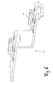
- the Fig. 1 shows two identical, electrical connection elements 10 according to the invention, which with their front end in the insertion direction 12 facing each other and perpendicular to the sheet metal plane of the sheet 16, from which the two connection elements 10 are made offset from each other.
- the two connection elements 10 are made of an electrically conductive metal sheet 16 with resilient properties of, for example, copper or aluminum alloys by punching and each have a cantilevered tongue 14, which is bent out of sheet metal plane on a first side A of the sheet and extending in a plane parallel to the sheet plane.
- connection element 12 By bending the tongue 14 out of the plane of the sheet, two fingers 17, 18 projecting freely in the insertion direction of the connection element 12 are formed, which are spaced apart by an elongated gap 20 which is open at the front end 12 of the connection element 10.
- the two fingers 17, 18 thus extend in the sheet plane parallel to the cantilevered tongue 14 and define in the insertion direction, the front end 12 of the connecting element 10th
- the connecting element 12 has a flat contacting section 22, which serves for the connection of an electrical conductor (not shown), which can be attached thereto, for example by crimping, soldering or welding.
- the front in the insertion direction X ends of the two cantilevered fingers 17, 18 of the two connecting elements 10 are connected in the illustrated embodiment by a web portion 24 which is located on the first side A of the sheet 16 opposite second side B of the sheet 16.
- the web portion 24 is formed by bending the front end of the sheet 16 and thus defines together with the free ends of the fingers 17, 18, the front end 12 of the connecting element 10. Since the web portion 24 extends on the second sheet side B below the plane of the sheet, the gap 20 between the fingers 17, 18 at the front end 12 of the connection element 10 is open and thus effectively serves as a receiving opening for the tongue 14 of the respective other connection element 10th
- the tongue 14 of the connecting element 10 has a bent out of the plane of the sheet ramp portion 26 and extending in a plane parallel to the plane parallel to the rear engaging portion 28 which projects freely from the ramp portion 26.
- the tongue 14 thus forms an elastic spring arm, which serves to clamp the other connecting element 10 between the two fingers 17, 18 and the tongue 14 itself, as will be explained in more detail below.
- the Schugreifungsabêt 28 at its free end on an inclined surface 30 which is inclined in the same direction as the bent out of the plane of the sheet ramp portion 26 of the tongue 14th
- the tongue 14 at its free end on a bulge, which extends on the second side B of the sheet 16, from which the tongue 14 has been bent.
- the fingers 17, 18 have contact bulges 34, which are spaced apart in the finger longitudinal direction.
- the contact bulges 34 of the fingers 17, 18 extend on the first side A of the sheet 16, in which they were embossed starting from the second side B, as shown by the right-hand connection element 10 of the Fig. 1 can be recognized.
- These contact bulges 34 in this case have an elongated, oval shape and are each aligned at 45 ° to the finger longitudinal direction, which can ensure that the respective associated contact bulges 34 of two connection elements 10 come crossed to lie on each other and thus form an overlap area in which the Connection elements 10 are securely in frictional engagement with each other.
- connection elements 10 With their front ends 12 are arranged at a distance from one another, wherein the first sheet-metal side A of one connection element 10 faces the first sheet-metal side A of the other connection element 10.
- the two connection elements 10 are approximately oriented and aligned such that the free end of the tongue 14 of the respective connection element 10 passes into the gap 20 between the fingers 17, 18 of the other connection element 10 when it starts, the two connection elements 10 in Plug direction X to each other to move.
- the two connection elements 10 should be slightly too offset from each other, as in the Fig.
- the elongated, oval contact bulges 34 of the two connection elements 10 are crosswise one above the other, whereby the two connection elements 10 are pressed against the spring force of the two tongues 14 perpendicular to the sheet plane, whereby the frictional engagement between the two connection elements 10 is increased. Due to the defined contact points in the form of the contact bulges 32, 34, however, not only in the desired manner, the frictional engagement between the two electrical connection elements 10 is increased; Rather, a uniformly distributed current flow over the electrical connection elements 10 can be achieved by the targeted arrangement of the contact bulges 32, 34, whereby their current strength can be influenced in a targeted manner.
- This offset of the front contact bulges 34 has the consequence that when mating two identical connection elements 10, the rear contact bulges 34 of the respective connection element 10 in succession with the mutually offset front contact bulges 34 of the other connecting element 10 come into contact, whereby the required insertion force of two connecting elements 10 to be interconnected increases less.
- the connecting element 10 can have a plurality of juxtaposed arrangements of tongue and finger, as shown in FIG Fig. 5 is shown.
- connection element 10 can also have a plurality of arrangements of tongue and fingers located one behind the other, as shown in FIG Fig. 6 is shown.
- the rear in the insertion direction X arrangement of tongue and fingers extends above the front of the arrangement of tongue and fingers, otherwise the free accessibility of the rear arrangement of tongue and fingers in the insertion direction X would be limited by the front tongue 14.
- connection element which has a plurality of juxtaposed and successively located arrangements of tongue and fingers, in which case the respective rear arrangement of tongue and fingers extends above the front of the arrangement of tongue and fingers.
- An electrical connection can be with the in the Fig. 5
- manufacture connecting element shown by being coupled to an identical connection element.
- this can be in the Fig. 5 shown connection element with two connection elements according to Fig. 4 couple, which in the Fig. 5 shown connecting element effectively serves as a busbar.
- connection element can be coupled either with an identical connection element.
- connection element with two individual connection elements according to Fig. 1 be coupled, whereby the connecting element of the Fig. 6 effectively serves as a busbar.
- more than two arrangements of tongue and fingers can be provided side by side and / or one behind the other on a single connection element, whereby its busbar character occurs even more clearly in appearance.
Priority Applications (1)
| Application Number | Priority Date | Filing Date | Title |
|---|---|---|---|
| EP11006296.5A EP2551963B8 (fr) | 2011-07-29 | 2011-07-29 | Elément de raccordement électrique |
Applications Claiming Priority (1)
| Application Number | Priority Date | Filing Date | Title |
|---|---|---|---|
| EP11006296.5A EP2551963B8 (fr) | 2011-07-29 | 2011-07-29 | Elément de raccordement électrique |
Publications (3)
| Publication Number | Publication Date |
|---|---|
| EP2551963A1 true EP2551963A1 (fr) | 2013-01-30 |
| EP2551963B1 EP2551963B1 (fr) | 2018-10-31 |
| EP2551963B8 EP2551963B8 (fr) | 2019-01-23 |
Family
ID=44645434
Family Applications (1)
| Application Number | Title | Priority Date | Filing Date |
|---|---|---|---|
| EP11006296.5A Active EP2551963B8 (fr) | 2011-07-29 | 2011-07-29 | Elément de raccordement électrique |
Country Status (1)
| Country | Link |
|---|---|
| EP (1) | EP2551963B8 (fr) |
Cited By (3)
| Publication number | Priority date | Publication date | Assignee | Title |
|---|---|---|---|---|
| DE202017003723U1 (de) * | 2017-07-14 | 2018-10-16 | WAGO Verwaltungsgesellschaft mit beschränkter Haftung | Steckverbinder |
| EP3451461A4 (fr) * | 2016-04-29 | 2019-05-08 | Avic Jonhon Optronic Technology Co., Ltd. | Contact électriquement conducteur et connecteur électrique utilisant celui-ci |
| EP3657570A1 (fr) | 2018-11-26 | 2020-05-27 | Aptiv Technologies Limited | Module de batterie |
Citations (6)
| Publication number | Priority date | Publication date | Assignee | Title |
|---|---|---|---|---|
| DE1141355B (de) * | 1959-02-10 | 1962-12-20 | Cannon Electric Company | Elektrische Verbinder |
| US3259869A (en) * | 1964-03-12 | 1966-07-05 | Kent J Batcheller | Electric connector member |
| JPS5881870U (ja) * | 1981-11-28 | 1983-06-02 | 不二電機工業株式会社 | 摺動接触子の構造 |
| JPS6119979U (ja) * | 1984-07-12 | 1986-02-05 | 株式会社フジクラ | 電気コネクタ |
| EP2065982A1 (fr) | 2007-11-30 | 2009-06-03 | Delphi Technologies, Inc. | Elément de raccordement électrique |
| US20090209143A1 (en) * | 2008-02-18 | 2009-08-20 | Chin-Pao Wu | Power source terminal structure |
-
2011
- 2011-07-29 EP EP11006296.5A patent/EP2551963B8/fr active Active
Patent Citations (6)
| Publication number | Priority date | Publication date | Assignee | Title |
|---|---|---|---|---|
| DE1141355B (de) * | 1959-02-10 | 1962-12-20 | Cannon Electric Company | Elektrische Verbinder |
| US3259869A (en) * | 1964-03-12 | 1966-07-05 | Kent J Batcheller | Electric connector member |
| JPS5881870U (ja) * | 1981-11-28 | 1983-06-02 | 不二電機工業株式会社 | 摺動接触子の構造 |
| JPS6119979U (ja) * | 1984-07-12 | 1986-02-05 | 株式会社フジクラ | 電気コネクタ |
| EP2065982A1 (fr) | 2007-11-30 | 2009-06-03 | Delphi Technologies, Inc. | Elément de raccordement électrique |
| US20090209143A1 (en) * | 2008-02-18 | 2009-08-20 | Chin-Pao Wu | Power source terminal structure |
Cited By (4)
| Publication number | Priority date | Publication date | Assignee | Title |
|---|---|---|---|---|
| EP3451461A4 (fr) * | 2016-04-29 | 2019-05-08 | Avic Jonhon Optronic Technology Co., Ltd. | Contact électriquement conducteur et connecteur électrique utilisant celui-ci |
| DE202017003723U1 (de) * | 2017-07-14 | 2018-10-16 | WAGO Verwaltungsgesellschaft mit beschränkter Haftung | Steckverbinder |
| EP3657570A1 (fr) | 2018-11-26 | 2020-05-27 | Aptiv Technologies Limited | Module de batterie |
| CN111224031A (zh) * | 2018-11-26 | 2020-06-02 | Aptiv技术有限公司 | 电池模块 |
Also Published As
| Publication number | Publication date |
|---|---|
| EP2551963B8 (fr) | 2019-01-23 |
| EP2551963B1 (fr) | 2018-10-31 |
Similar Documents
| Publication | Publication Date | Title |
|---|---|---|
| EP1999820B1 (fr) | Borne de connexion pour cartes de circuit imprimé | |
| EP2866306B1 (fr) | Prise de contact pour un connecteur à fiches électrique | |
| EP2131449A1 (fr) | Borne unique | |
| EP2852003B1 (fr) | Élément de contact pour un connecteur à fiche | |
| EP1503457B1 (fr) | Connecteur femelle pour fiche plate | |
| EP3196981B1 (fr) | Connecteur transversal pour bornier | |
| EP3378128B1 (fr) | Arrangement avec un élément de contact et un câble électrique et méthode pour la production d'un tel arrangement | |
| DE102012219741A1 (de) | Elektrischer Kontakt und Steckverbinder mit einem solchen elektrischen Kontakt | |
| EP2915218B1 (fr) | Connecteur à fiche à partie isolante | |
| EP3482460B1 (fr) | Contact électrique à grande puissance | |
| EP3843221A1 (fr) | Cadre de support pour un connecteur | |
| EP2243198B1 (fr) | Connecteur enfichable coaxial coudé | |
| EP2297820B1 (fr) | Dispositif métallique de connexion d un conducteur de protection | |
| EP2551963B1 (fr) | Elément de raccordement électrique | |
| EP3118936A1 (fr) | Connecteur a fiches et outil de deformation associe | |
| EP3446367B1 (fr) | Contact enfichable | |
| EP1587172B1 (fr) | Douille pour connection électrique avec une fiche plus particulièrement une fiche plate | |
| DE102011051231B4 (de) | Klemmkörper, elektrische Anschlussklemme und Verfahren zur Herstellung eines Klemmkörpers | |
| DE102015211725B4 (de) | Verbinderanschluss und Verbinder hiermit | |
| EP3069416B1 (fr) | Barrette de raccordement et adaptateurs de borne à ressort | |
| EP3539183B1 (fr) | Élément de contact à raccordement par serrage pour conducteur multibrin | |
| DE102012201124B4 (de) | Kontaktelement | |
| EP2771949B1 (fr) | Connexion enfichable comprenant un ressort de contact de protection | |
| EP1974417A1 (fr) | Dispositif pour raccorder un élément de liaison | |
| EP1939987B1 (fr) | Dispositif de contact |
Legal Events
| Date | Code | Title | Description |
|---|---|---|---|
| PUAI | Public reference made under article 153(3) epc to a published international application that has entered the european phase |
Free format text: ORIGINAL CODE: 0009012 |
|
| AK | Designated contracting states |
Kind code of ref document: A1 Designated state(s): AL AT BE BG CH CY CZ DE DK EE ES FI FR GB GR HR HU IE IS IT LI LT LU LV MC MK MT NL NO PL PT RO RS SE SI SK SM TR |
|
| AX | Request for extension of the european patent |
Extension state: BA ME |
|
| 17P | Request for examination filed |
Effective date: 20130321 |
|
| GRAP | Despatch of communication of intention to grant a patent |
Free format text: ORIGINAL CODE: EPIDOSNIGR1 |
|
| STAA | Information on the status of an ep patent application or granted ep patent |
Free format text: STATUS: GRANT OF PATENT IS INTENDED |
|
| GRAJ | Information related to disapproval of communication of intention to grant by the applicant or resumption of examination proceedings by the epo deleted |
Free format text: ORIGINAL CODE: EPIDOSDIGR1 |
|
| STAA | Information on the status of an ep patent application or granted ep patent |
Free format text: STATUS: REQUEST FOR EXAMINATION WAS MADE |
|
| INTG | Intention to grant announced |
Effective date: 20180403 |
|
| GRAP | Despatch of communication of intention to grant a patent |
Free format text: ORIGINAL CODE: EPIDOSNIGR1 |
|
| STAA | Information on the status of an ep patent application or granted ep patent |
Free format text: STATUS: GRANT OF PATENT IS INTENDED |
|
| INTC | Intention to grant announced (deleted) | ||
| INTG | Intention to grant announced |
Effective date: 20180518 |
|
| GRAS | Grant fee paid |
Free format text: ORIGINAL CODE: EPIDOSNIGR3 |
|
| GRAA | (expected) grant |
Free format text: ORIGINAL CODE: 0009210 |
|
| STAA | Information on the status of an ep patent application or granted ep patent |
Free format text: STATUS: THE PATENT HAS BEEN GRANTED |
|
| AK | Designated contracting states |
Kind code of ref document: B1 Designated state(s): AL AT BE BG CH CY CZ DE DK EE ES FI FR GB GR HR HU IE IS IT LI LT LU LV MC MK MT NL NO PL PT RO RS SE SI SK SM TR |
|
| REG | Reference to a national code |
Ref country code: CH Ref legal event code: EP Ref country code: GB Ref legal event code: FG4D Free format text: NOT ENGLISH |
|
| REG | Reference to a national code |
Ref country code: AT Ref legal event code: REF Ref document number: 1060527 Country of ref document: AT Kind code of ref document: T Effective date: 20181115 |
|
| REG | Reference to a national code |
Ref country code: DE Ref legal event code: R096 Ref document number: 502011014921 Country of ref document: DE |
|
| REG | Reference to a national code |
Ref country code: IE Ref legal event code: FG4D Free format text: LANGUAGE OF EP DOCUMENT: GERMAN |
|
| REG | Reference to a national code |
Ref country code: DE Ref legal event code: R081 Ref document number: 502011014921 Country of ref document: DE Owner name: APTIV TECHNOLOGIES LIMITED, BB Free format text: FORMER OWNER: DELPHI TECHNOLOGIES, INC., TROY, MICH., US |
|
| RAP2 | Party data changed (patent owner data changed or rights of a patent transferred) |
Owner name: APTIV TECHNOLOGIES LIMITED |
|
| REG | Reference to a national code |
Ref country code: CH Ref legal event code: PK Free format text: BERICHTIGUNG B8 |
|
| REG | Reference to a national code |
Ref country code: NL Ref legal event code: MP Effective date: 20181031 |
|
| REG | Reference to a national code |
Ref country code: LT Ref legal event code: MG4D |
|
| PG25 | Lapsed in a contracting state [announced via postgrant information from national office to epo] |
Ref country code: FI Free format text: LAPSE BECAUSE OF FAILURE TO SUBMIT A TRANSLATION OF THE DESCRIPTION OR TO PAY THE FEE WITHIN THE PRESCRIBED TIME-LIMIT Effective date: 20181031 Ref country code: BG Free format text: LAPSE BECAUSE OF FAILURE TO SUBMIT A TRANSLATION OF THE DESCRIPTION OR TO PAY THE FEE WITHIN THE PRESCRIBED TIME-LIMIT Effective date: 20190131 Ref country code: IS Free format text: LAPSE BECAUSE OF FAILURE TO SUBMIT A TRANSLATION OF THE DESCRIPTION OR TO PAY THE FEE WITHIN THE PRESCRIBED TIME-LIMIT Effective date: 20190228 Ref country code: ES Free format text: LAPSE BECAUSE OF FAILURE TO SUBMIT A TRANSLATION OF THE DESCRIPTION OR TO PAY THE FEE WITHIN THE PRESCRIBED TIME-LIMIT Effective date: 20181031 Ref country code: LV Free format text: LAPSE BECAUSE OF FAILURE TO SUBMIT A TRANSLATION OF THE DESCRIPTION OR TO PAY THE FEE WITHIN THE PRESCRIBED TIME-LIMIT Effective date: 20181031 Ref country code: HR Free format text: LAPSE BECAUSE OF FAILURE TO SUBMIT A TRANSLATION OF THE DESCRIPTION OR TO PAY THE FEE WITHIN THE PRESCRIBED TIME-LIMIT Effective date: 20181031 Ref country code: LT Free format text: LAPSE BECAUSE OF FAILURE TO SUBMIT A TRANSLATION OF THE DESCRIPTION OR TO PAY THE FEE WITHIN THE PRESCRIBED TIME-LIMIT Effective date: 20181031 Ref country code: PL Free format text: LAPSE BECAUSE OF FAILURE TO SUBMIT A TRANSLATION OF THE DESCRIPTION OR TO PAY THE FEE WITHIN THE PRESCRIBED TIME-LIMIT Effective date: 20181031 Ref country code: NO Free format text: LAPSE BECAUSE OF FAILURE TO SUBMIT A TRANSLATION OF THE DESCRIPTION OR TO PAY THE FEE WITHIN THE PRESCRIBED TIME-LIMIT Effective date: 20190131 |
|
| PG25 | Lapsed in a contracting state [announced via postgrant information from national office to epo] |
Ref country code: NL Free format text: LAPSE BECAUSE OF FAILURE TO SUBMIT A TRANSLATION OF THE DESCRIPTION OR TO PAY THE FEE WITHIN THE PRESCRIBED TIME-LIMIT Effective date: 20181031 Ref country code: RS Free format text: LAPSE BECAUSE OF FAILURE TO SUBMIT A TRANSLATION OF THE DESCRIPTION OR TO PAY THE FEE WITHIN THE PRESCRIBED TIME-LIMIT Effective date: 20181031 Ref country code: PT Free format text: LAPSE BECAUSE OF FAILURE TO SUBMIT A TRANSLATION OF THE DESCRIPTION OR TO PAY THE FEE WITHIN THE PRESCRIBED TIME-LIMIT Effective date: 20190301 Ref country code: AL Free format text: LAPSE BECAUSE OF FAILURE TO SUBMIT A TRANSLATION OF THE DESCRIPTION OR TO PAY THE FEE WITHIN THE PRESCRIBED TIME-LIMIT Effective date: 20181031 Ref country code: SE Free format text: LAPSE BECAUSE OF FAILURE TO SUBMIT A TRANSLATION OF THE DESCRIPTION OR TO PAY THE FEE WITHIN THE PRESCRIBED TIME-LIMIT Effective date: 20181031 Ref country code: GR Free format text: LAPSE BECAUSE OF FAILURE TO SUBMIT A TRANSLATION OF THE DESCRIPTION OR TO PAY THE FEE WITHIN THE PRESCRIBED TIME-LIMIT Effective date: 20190201 |
|
| PG25 | Lapsed in a contracting state [announced via postgrant information from national office to epo] |
Ref country code: IT Free format text: LAPSE BECAUSE OF FAILURE TO SUBMIT A TRANSLATION OF THE DESCRIPTION OR TO PAY THE FEE WITHIN THE PRESCRIBED TIME-LIMIT Effective date: 20181031 Ref country code: CZ Free format text: LAPSE BECAUSE OF FAILURE TO SUBMIT A TRANSLATION OF THE DESCRIPTION OR TO PAY THE FEE WITHIN THE PRESCRIBED TIME-LIMIT Effective date: 20181031 Ref country code: DK Free format text: LAPSE BECAUSE OF FAILURE TO SUBMIT A TRANSLATION OF THE DESCRIPTION OR TO PAY THE FEE WITHIN THE PRESCRIBED TIME-LIMIT Effective date: 20181031 |
|
| REG | Reference to a national code |
Ref country code: DE Ref legal event code: R097 Ref document number: 502011014921 Country of ref document: DE |
|
| PG25 | Lapsed in a contracting state [announced via postgrant information from national office to epo] |
Ref country code: SM Free format text: LAPSE BECAUSE OF FAILURE TO SUBMIT A TRANSLATION OF THE DESCRIPTION OR TO PAY THE FEE WITHIN THE PRESCRIBED TIME-LIMIT Effective date: 20181031 Ref country code: EE Free format text: LAPSE BECAUSE OF FAILURE TO SUBMIT A TRANSLATION OF THE DESCRIPTION OR TO PAY THE FEE WITHIN THE PRESCRIBED TIME-LIMIT Effective date: 20181031 Ref country code: RO Free format text: LAPSE BECAUSE OF FAILURE TO SUBMIT A TRANSLATION OF THE DESCRIPTION OR TO PAY THE FEE WITHIN THE PRESCRIBED TIME-LIMIT Effective date: 20181031 Ref country code: SK Free format text: LAPSE BECAUSE OF FAILURE TO SUBMIT A TRANSLATION OF THE DESCRIPTION OR TO PAY THE FEE WITHIN THE PRESCRIBED TIME-LIMIT Effective date: 20181031 |
|
| PLBE | No opposition filed within time limit |
Free format text: ORIGINAL CODE: 0009261 |
|
| STAA | Information on the status of an ep patent application or granted ep patent |
Free format text: STATUS: NO OPPOSITION FILED WITHIN TIME LIMIT |
|
| 26N | No opposition filed |
Effective date: 20190801 |
|
| PG25 | Lapsed in a contracting state [announced via postgrant information from national office to epo] |
Ref country code: SI Free format text: LAPSE BECAUSE OF FAILURE TO SUBMIT A TRANSLATION OF THE DESCRIPTION OR TO PAY THE FEE WITHIN THE PRESCRIBED TIME-LIMIT Effective date: 20181031 |
|
| PG25 | Lapsed in a contracting state [announced via postgrant information from national office to epo] |
Ref country code: MC Free format text: LAPSE BECAUSE OF FAILURE TO SUBMIT A TRANSLATION OF THE DESCRIPTION OR TO PAY THE FEE WITHIN THE PRESCRIBED TIME-LIMIT Effective date: 20181031 |
|
| REG | Reference to a national code |
Ref country code: CH Ref legal event code: PL |
|
| PG25 | Lapsed in a contracting state [announced via postgrant information from national office to epo] |
Ref country code: TR Free format text: LAPSE BECAUSE OF FAILURE TO SUBMIT A TRANSLATION OF THE DESCRIPTION OR TO PAY THE FEE WITHIN THE PRESCRIBED TIME-LIMIT Effective date: 20181031 |
|
| REG | Reference to a national code |
Ref country code: BE Ref legal event code: MM Effective date: 20190731 |
|
| PG25 | Lapsed in a contracting state [announced via postgrant information from national office to epo] |
Ref country code: CH Free format text: LAPSE BECAUSE OF NON-PAYMENT OF DUE FEES Effective date: 20190731 Ref country code: LI Free format text: LAPSE BECAUSE OF NON-PAYMENT OF DUE FEES Effective date: 20190731 Ref country code: LU Free format text: LAPSE BECAUSE OF NON-PAYMENT OF DUE FEES Effective date: 20190729 Ref country code: BE Free format text: LAPSE BECAUSE OF NON-PAYMENT OF DUE FEES Effective date: 20190731 |
|
| PG25 | Lapsed in a contracting state [announced via postgrant information from national office to epo] |
Ref country code: IE Free format text: LAPSE BECAUSE OF NON-PAYMENT OF DUE FEES Effective date: 20190729 |
|
| REG | Reference to a national code |
Ref country code: AT Ref legal event code: MM01 Ref document number: 1060527 Country of ref document: AT Kind code of ref document: T Effective date: 20190729 |
|
| PG25 | Lapsed in a contracting state [announced via postgrant information from national office to epo] |
Ref country code: AT Free format text: LAPSE BECAUSE OF NON-PAYMENT OF DUE FEES Effective date: 20190729 |
|
| PG25 | Lapsed in a contracting state [announced via postgrant information from national office to epo] |
Ref country code: CY Free format text: LAPSE BECAUSE OF FAILURE TO SUBMIT A TRANSLATION OF THE DESCRIPTION OR TO PAY THE FEE WITHIN THE PRESCRIBED TIME-LIMIT Effective date: 20181031 |
|
| PG25 | Lapsed in a contracting state [announced via postgrant information from national office to epo] |
Ref country code: MT Free format text: LAPSE BECAUSE OF FAILURE TO SUBMIT A TRANSLATION OF THE DESCRIPTION OR TO PAY THE FEE WITHIN THE PRESCRIBED TIME-LIMIT Effective date: 20181031 Ref country code: HU Free format text: LAPSE BECAUSE OF FAILURE TO SUBMIT A TRANSLATION OF THE DESCRIPTION OR TO PAY THE FEE WITHIN THE PRESCRIBED TIME-LIMIT; INVALID AB INITIO Effective date: 20110729 |
|
| PG25 | Lapsed in a contracting state [announced via postgrant information from national office to epo] |
Ref country code: MK Free format text: LAPSE BECAUSE OF FAILURE TO SUBMIT A TRANSLATION OF THE DESCRIPTION OR TO PAY THE FEE WITHIN THE PRESCRIBED TIME-LIMIT Effective date: 20181031 |
|
| P01 | Opt-out of the competence of the unified patent court (upc) registered |
Effective date: 20230420 |
|
| PGFP | Annual fee paid to national office [announced via postgrant information from national office to epo] |
Ref country code: GB Payment date: 20230718 Year of fee payment: 13 |
|
| PGFP | Annual fee paid to national office [announced via postgrant information from national office to epo] |
Ref country code: FR Payment date: 20230724 Year of fee payment: 13 Ref country code: DE Payment date: 20230725 Year of fee payment: 13 |