EP2551663A1 - Dispositif et procédé d'examen de revêtements à l'aide de pigments à effet - Google Patents
Dispositif et procédé d'examen de revêtements à l'aide de pigments à effet Download PDFInfo
- Publication number
- EP2551663A1 EP2551663A1 EP12153282A EP12153282A EP2551663A1 EP 2551663 A1 EP2551663 A1 EP 2551663A1 EP 12153282 A EP12153282 A EP 12153282A EP 12153282 A EP12153282 A EP 12153282A EP 2551663 A1 EP2551663 A1 EP 2551663A1
- Authority
- EP
- European Patent Office
- Prior art keywords
- radiation
- image
- wavelength range
- light
- onto
- Prior art date
- Legal status (The legal status is an assumption and is not a legal conclusion. Google has not performed a legal analysis and makes no representation as to the accuracy of the status listed.)
- Granted
Links
Images


Classifications
-
- G—PHYSICS
- G01—MEASURING; TESTING
- G01N—INVESTIGATING OR ANALYSING MATERIALS BY DETERMINING THEIR CHEMICAL OR PHYSICAL PROPERTIES
- G01N21/00—Investigating or analysing materials by the use of optical means, i.e. using sub-millimetre waves, infrared, visible or ultraviolet light
- G01N21/17—Systems in which incident light is modified in accordance with the properties of the material investigated
- G01N21/47—Scattering, i.e. diffuse reflection
- G01N21/4738—Diffuse reflection, e.g. also for testing fluids, fibrous materials
- G01N21/474—Details of optical heads therefor, e.g. using optical fibres
-
- G—PHYSICS
- G01—MEASURING; TESTING
- G01N—INVESTIGATING OR ANALYSING MATERIALS BY DETERMINING THEIR CHEMICAL OR PHYSICAL PROPERTIES
- G01N21/00—Investigating or analysing materials by the use of optical means, i.e. using sub-millimetre waves, infrared, visible or ultraviolet light
- G01N21/17—Systems in which incident light is modified in accordance with the properties of the material investigated
- G01N21/55—Specular reflectivity
-
- G—PHYSICS
- G01—MEASURING; TESTING
- G01N—INVESTIGATING OR ANALYSING MATERIALS BY DETERMINING THEIR CHEMICAL OR PHYSICAL PROPERTIES
- G01N21/00—Investigating or analysing materials by the use of optical means, i.e. using sub-millimetre waves, infrared, visible or ultraviolet light
- G01N21/84—Systems specially adapted for particular applications
- G01N21/88—Investigating the presence of flaws or contamination
- G01N21/8806—Specially adapted optical and illumination features
-
- G—PHYSICS
- G01—MEASURING; TESTING
- G01N—INVESTIGATING OR ANALYSING MATERIALS BY DETERMINING THEIR CHEMICAL OR PHYSICAL PROPERTIES
- G01N21/00—Investigating or analysing materials by the use of optical means, i.e. using sub-millimetre waves, infrared, visible or ultraviolet light
- G01N21/17—Systems in which incident light is modified in accordance with the properties of the material investigated
- G01N2021/1765—Method using an image detector and processing of image signal
Definitions
- the present invention relates to an apparatus and method for inspecting surfaces, and more particularly coatings.
- the invention will be described with reference to so-called effect coatings, that is those coatings which have so-called effect pigments.
- effect pigments cause the relevant layer to shine or glitter or assume a certain color under certain conditions, for example with a light incident at a certain angle.
- effect pigments are known from the prior art and also very different optical properties of the same.
- these effect pigments can have a wide variety of color changes.
- the DE 10 2007 014 474 A1 describes a method and an apparatus for the quantitative determination of surface properties. Also in this method, a result value is determined and this result value is displayed against the size of the determined area proportions.
- the subject matter of this disclosure is hereby fully incorporated by reference into the subject of the present application.
- the DE 10 2006 048 688 A1 refers to a method and apparatus for examining surfaces with effect pigments.
- a surface to be examined is likewise examined under different angles of incidence or absorption and closed on the basis of these different angles on a curvature of the effect pigments.
- the disclosure of this document is hereby incorporated by reference in its entirety to the disclosure content of the present application.
- a device for investigating surface properties with indirect illumination is known.
- a radiation scattering device is provided which is at least partially illuminated by the first illumination device and which scattered radiation transmits to the surface to be examined.
- Measuring devices or devices are known from the prior art, which also serve for the color or optical detection of such coatings.
- these devices usually have a plurality of light sources which direct specific light, for example standardized white light, at different angles onto the respective surface provided with the coating.
- the radiation reflected by this surface is recorded by a camera, such as a CCD color camera, and the images are evaluated accordingly.
- Such color image cameras usually have an array with a plurality of photodetectors, in addition to those detectors used to detect red light components, the detectors used to detect green light components and the Detectors, each serving to detect blue light components are arranged in any case still slightly different positions.
- the individual illumination source can be individually supplied with power. This makes it possible to optimize the brightness of this illumination, e.g. Adjust the sample or the sensor characteristic and thus achieves maximum measurement dynamics for each illumination.
- a radiation detector device with a black-and-white image pickup unit arranged at a predetermined detection angle with respect to the surface.
- this radiation detector device allows a spatially resolved detection of the radiation impinging on them.
- a camera can generally also be used, which has only one type of image recording elements in a plane perpendicular to the light irradiation direction, this camera or each individual image recording element of this camera both for output an information about the radiation intensity as well as for the output of information about the irradiated wavelengths in the situation. This can be done by arranging the pixels for the different color components one behind the other in the direction of irradiation.
- the radiation device directs radiation having a first wavelength range onto the surface, and the image acquisition unit picks up a first spatially resolved image of this beam, which is scattered and / or reflected by the surface, that is, generally passed on.
- the radiation device directs radiation having a second wavelength range onto the surface and the image recording unit records a second spatially resolved image of this radiation scattered and / or reflected by the surface.
- the radiation with the first wavelength range and the radiation with the second wavelength range differ at least partially from one another, and these radiations reach the surface at least partially offset in time.
- the radiation with the first wavelength range and the radiation with the second wavelength range at the same angle of incidence are irradiated onto the surface.
- the spatially resolved image does not only mean the actual image, but also a multiplicity of data (for example intensity values) from which this image is composed or derived.
- the radiation scattered and / or reflected by the surface is generally that radiation which, as a consequence of the radiation irradiated by the radiation device, is passed on, in particular being passed on to the image recording device.
- This threshold determination can be applied both locally and in a brightness histogram.
- the threshold value can be used as a fixed value or as a dynamic value, which can be determined, for example, as a function of the overall brightness of the image or of an image contrast value.
- the mathematical thresholding is fixed or dynamic and the thresholding is derived from image information such as image brightness, image contrast.
- the optical properties of the effect pigments can be determined under the respective illumination angle. What applies in particular to the optical characterization of effect flakes is also applicable to the overall surface.
- the irradiation of the surface with radiation takes place with the first wavelength range and the irradiation with radiation with the second wavelength range is completely offset in time from one another.
- the wavelengths of the two radiations which are directed onto the surface are also completely separated from one another. For example, green light is used at a first impact and red light at a second impact.
- the image acquisition unit is an image acquisition unit which has a large number of identical photographic elements, that is to say in particular has only one specific type of photoelements and is therefore only suitable for taking black / white or gray scale images.
- the individual dark value or sensitivity or linearity which is e.g. calculated by a preliminary calibration were considered mathematically. This compensates for component tolerances that can occur between individual pixels or other artifacts. Unlike the use of a color camera, the differences between the individual color pixels need not be taken into account here, or information should not be separated into color pixels.
- the first image taken by the image recording unit and the second image taken by the image recording unit are compared and / or compared with one another. More specifically, advantageously, the (intensity) values characteristic of the respective images are compared with each other. In this way, in particular the color components of the light impinging on the image recording unit can be evaluated.
- this comparison also takes place spatially resolved or pixel-wise. This makes it possible for the individual signals of the individual pixel elements of the image acquisition unit to be compared with each other. If one summarizes several pixel elements which correspond to the image of an effect pigment, one thereby obtains the (preferably averaged) pigment-specific properties. By offsetting the images or the characteristic intensity values, these values can be multiplied together, for example, or subjected to other mathematical operations such as averaging summations and the like together.
- this comparison - especially for the purpose of this comparison - images or sections of these images are mathematically brought to coincidence. It can be either a (in particular pixelwise) comparison of the entire pictures take place or the comparison may refer to individual pixel areas of the image. In this case, those pixel areas or pixel areas are preferably selected for the comparison, which largely correspond to the image of the effect pigments. To determine these districts, the thresholding described above can be used
- the surface is a surface provided with a lacquer layer.
- This may, for example and preferably, be the surfaces of vehicle bodies, but it would also be possible for the surfaces to be surfaces of pieces of furniture, for example tables or the like.
- the lacquer layer has pigments, for example effect pigments.
- these effect pigments may, for example, be small metal particles present in the layer.
- these effect pigments have a flop behavior, that is, for example, a certain color change or intensity change, depending on the angle at which the light impinges on the pigments.
- the radiation device is designed in such a way that the radiations under the two different wavelengths radiate onto the surface at exactly the same angle.
- the radiations with the first wavelength range and the radiations with the second wavelength range are collinear with one another on the surface.
- radiation with a third wavelength range extending from the first wavelength range is additionally included below the first angle of incidence and also different from the second wavelength range, irradiated on the surface, and the image pickup unit receives the radiation reflected and / or scattered by the surface, and thus continues to take a third spatially resolved image.
- this third image With a time offset to the other two images. It is thus possible, for example, for light to be irradiated onto the surface under three different colors, for example red, green and blue. By comparing the images, the colors of the individual pigments can be determined in this way, or the colors under which the pigments reflect light back. If, for example, a particular pixel of the image acquisition unit shows a high intensity value in the red region at a certain point, it can be concluded from this that the corresponding sparkle or effect pigment reflects back the light, in particular with a red wavelength range.
- the color value of the effect pigments contained in the paint can be approximated in the dimensional content for color, e.g. the CIELab system.
- radiation from a plurality of radiation devices is irradiated onto the surface at different angles and subsequently recorded by the image recording device.
- the radiation device it would also be possible for the radiation device to emit only one wavelength range and to separate the wavelengths on the other side on the detector side, for example by pushing different filter elements in front of the radiation detector device.
- several images are taken by the black and white image camera, but also different color aspects are analyzed here, or spatially resolved images are taken under different color aspects.
- the two wavelength ranges of the radiation emitted by the radiation device preferably do not differ here, but instead the wavelength of the radiation impinging on the image recording unit.
- radiation is directed onto the surface with a plurality of radiation devices and different radiation angles. For example, at certain angles such as 45 °, 15 ° or 60 ° light could be radiated onto the surface.
- the radiation is light and more preferably light in the visible wavelength range.
- the present invention is further directed to an apparatus for inspecting optical surface properties.
- This device has a first radiation device, which directs radiation at a predetermined angle of incidence onto a surface to be examined. Furthermore, the device has a radiation detector device, which receives the radiation radiated onto the surface from the first radiation device and reflected or propagated from the surface under a detection angle. In this case, the radiation detector device has a spatially resolved black and white image-capturing image recording unit.
- the radiation device is designed in such a way that it is suitable for outputting radiation in at least two different wavelength ranges under the same angle of incidence at least partially with respect to time, and the image acquisition unit until the acquisition of a first image which corresponds to the radiation with the first wavelength range corresponds to the radiation having the first wavelength range and is suitable for receiving a second image.
- the image recording unit records images of radiations with two different wavelengths and these different wavelengths are irradiated in each case at the same angle of incidence on the surface.
- the image recording unit records images of radiations with two different wavelengths and these different wavelengths are irradiated in each case at the same angle of incidence on the surface.
- the radiation device is also suitable for emitting radiation with a third wavelength range and, advantageously, the image recording unit also for recording a third spatially resolved image (thus the said wavelength range).
- the device has a comparison device which compares at least the first image with the second image.
- a comparison device which compares at least the first image with the second image.
- color characteristics of the surface or of the effect pigments can be concluded with this comparison.
- the device has a plurality of radiation devices which illuminate the surface at different angles.
- a plurality of radiation devices and particularly preferably all of the radiation devices are suitable for emitting light in different wavelength ranges.
- these radiation devices irradiate the light at different angles to the surface.
- the radiation device has a first light source, which emits radiation in the first wavelength range and a second light wave, which emits radiation in the second wavelength range and a Strahlungsleitan Aunt, which causes the radiation in the first wavelength range and the radiation in the second wavelength range are irradiated to the surface under the same angle of incidence.
- the first light source and preferably also the second light wave are each advantageously light emitting diodes. These light-emitting diodes can direct light in different wavelength ranges to the surface.
- the radiation guide arrangement causes the radiation of the first light source and the second light source to strike the surface substantially collinearly.
- Strahlungsleitan angel it would also be possible that only one light source is provided and for several filter elements which can be pushed in front of this light source. Also in this way it would be possible to collinear light with different wavelengths on the To throw surface, in which case, however, the intensity of the incident on the surface radiation is attenuated respectively by the filter elements.
- the radiation guide arrangement has at least one mirror element.
- this mirror element can be a dichroic mirror which allows light of a certain wavelength to pass through and more or less completely reflects (or absorbs) light of a further wavelength.
- other elements such as lenses, lenses and the like may find application.
- the device has at least one processor device which, from a comparison of the recorded images, determines information which is characteristic of a color of at least one section of the surface.
- a property is determined which is characteristic of the sparkles or an optical behavior of at least one effect pigment and preferably a multiplicity of effect pigments.
- the processor device thus evaluates the respective images spatially resolved and therefore also carries out a comparison in each case in a spatially resolved or individual manner for the respective pixels of the image recording unit.
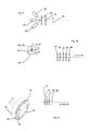
- the Figures 1a-1c show three examples of pigments.
- the surface or the coating has absorbent pigments 15a. These absorbing pigments 15a have a specific color and the paint color is formed by selective absorption and scattering of the light in all directions.
- metallic effect pigments 15b are arranged in the surface or in the coating. These effect pigments create a metallic sheen by specular reflection of the light.
- Pigments 15c shown are pearlescent pigments, which also have a specific color and a pearlescent, but in addition a color change or color flop can occur due to interference of the reflected light.
- color flops can be both a light / dark flop and a color flop.
- the color impression is also dependent on the lighting and observation geometry.
- Color-colored substrates such as glass flakes or SIO 2- based flakes, which reflect the light in a specific direction, are also used.
- FIG. 2 shows an example of an image pickup unit 4a in the form of a color image camera or a color image CCD chip.
- this image recording unit 4a has a multiplicity of image recording elements 14, which in turn are subdivided into individual subelements 14a, 14b, 14c, which are suitable for recording different colors.
- the subelements 14a marked with R serve to receive light in the red color region
- the subelements 14b marked with G to receive light in the green color region
- the subelements 14c denoted by B to receive light in the blue spectral region. If, however, the light reflected by the effect pigments, for example 15c, has a predominantly red component, but reaches the elements 14b or 14c, these will output an incorrect value for the intensity.
- image pickup element 4a instead of the in FIG. 2 shown image pickup element 4a to use an image pickup element having a plurality of uniform detectors and which therefore can only record or output black and white images.
- FIG. 3 shows correspondingly an embodiment according to the invention of a device 1 for examining optical surface properties.
- a radiation device 2 which has an image recording unit 4a.
- This image recording unit 4a may be suitable for recording spatially resolved images B1, B2, which are each black and white images, or data sets that are characteristic of such images.
- the radiation device 2 directs radiation with a first wavelength range W1 and with a second wavelength range W2 on the surface. This irradiation takes place as mentioned above temporally offset.
- radiation with the wavelength range W3 can also be irradiated onto the surface.
- the reference symbol a1 denotes the angle of incidence under which the radiation from the radiation device 2 is irradiated onto the surface 10. This angle is indicated here in relation to a direction perpendicular to the surface.
- the angle b 2 at which the radiation is received by the radiation detector device 4 is is, 0 °, ie the radiation is preferably recorded under a direction perpendicular to the surface direction.
- the reference numeral 50 denotes a processor device which serves to evaluate the images taken by the image pickup unit 4a.
- the processor device 50 in this case has a comparison device 52 which compares the recorded images with one another. In this way, for example, the intensities recorded in the different color areas (from the black and white image camera) can be recorded. From this comparison of intensities, it is also possible to deduce the color impression of corresponding effect pigments.
- the reference numeral 54 denotes a memory device in which the individual images taken by the image recording device 4 or the individual values from which these images can be derived are stored. In this memory device position data can be stored, which are characteristic of a position of the device 1 relative to the surface.
- the device 1 may further comprise an output device for displaying the data, such as a display or the like.
- the various images or flakes are brought to coincide with the aid of suitable algorithms. This determines the pixels belonging to a flake from all images.
- the device according to the invention also has a position or distance detection device in order to be able to compare two recordings, which were recorded at different locations of the surface 10, also with regard to their spacing. In this way it is possible to measure a complete surface, for example the part of a body of a vehicle, by means of a large number of recordings. It is possible that both the radiation device 2 and the radiation detector device 4 are arranged in a housing 60 and this housing advantageously has essentially an opening 62 in a region in which the radiation is to emerge onto the surface.
- a wheel 64 which serves to move the device 1 relative to the surface 10, can be arranged on the housing 60.
- This bike can also be beneficial serve to determine distances.
- the device 1 it would also be possible for the device 1 to be held on a moving element such as, for example, a robot arm and thus moved relative to the surface 10 to be examined.
- the images taken by the image recording device are also assigned positions of the device relative to the surface 10, or data which are characteristic of these positions. This assignment is advantageously carried out by means of a processor device.
- FIG. 4 shows a further embodiment of the device according to the invention.
- a plurality of radiation devices 2 are provided, which irradiate the light at different angles (in each case shown with respect to the vertical with respect to the surface 10).
- the surface is illuminated under the said different angles and the light is in each case received in a direction perpendicular to the surface 10 direction.
- Each of these radiation devices can be designed in the manner described above, that is, be suitable for the time-shifted output of radiations of different wavelengths.
- the device has at least two such radiation devices, which radiate the radiation at different angles onto the surface, and particularly preferably at least three radiation devices which radiate the radiation onto the surface 10 at different angles.
- the irradiation directions of a plurality of radiation devices and the beam direction of the radiation transmitted from the surface 10 to the image recording device 4 are in one plane. But it is also conceivable that radiation receiver and radiation device are not in one plane.
- FIG. 5 shows a representation of a radiation device 2.
- This radiation device here has a first radiation or light source 22 and a second radiation or light source 24.
- the first radiation source 22 emits a light beam S1 having a wavelength range W1, which strikes a mirror element 46, which may be a dichroic mirror here.
- the light beam S1 passes through this mirror element 46 due to its wavelength.
- the light source 24 also directs a second beam component S2 having a wavelength range W2 onto the mirror element 46.
- This mirror element 46 is designed such that it reflects the radiation S2 due to the other wavelength so that both the radiation S1 and the radiation S2 are collinear with one another Radiation device 2 escape.
- the two radiations S1 and S2 were shown offset to each other to illustrate the operation, but in fact the two radiations S1 and S2 would lie directly above each other.
- the reference numeral 32 refers to an optical element, such as a diffuser, on which the light coming from the light source 22 or 24 impinges.
- Reference numeral 34 denotes another optical element such as a lens device which serves to bundle the radiation S1 and S2, respectively.
- the reference numeral 36 may represent another optical element, such as a filter element, which will leak only a certain wavelength portion.
- Reference numeral 38 refers to an aperture device which also serves to form a clean light beam S1 and S2, respectively.
- the order of the elements 32, 34, 36, 38 in the direction of the light beams can also be designed differently depending on the application.
- a further light source 26 could also be provided which, for example, in FIG FIG. 5 to the right of the light source 24 and which also directs a beam S3 (not shown) vertically downwards onto another mirror element (not shown).
- a beam S3 (not shown) vertically downwards onto another mirror element (not shown).
- Optical elements 32, 34, 36, 38 could also be arranged after the mirror elements 46.
- FIG. 6 shows a further embodiment of a radiation device 2.
- three radiation sources 22, 24, 26 are provided, each of which direct their light onto a lens 32.
- the diffusing screen can be a holographic optical element.
- the light sources 22, 24, 26 are arranged such that they direct their light to a same area or the same point of the lens 32.
- reflective elements such as, for example, lenses, cylindrical lenses, apertured diaphragms and the like, may be arranged between the light sources and the diffusing screen 32.
- other optical elements such as lenses 34 or pinhole apertures 38 or the like may be provided.
- the reference numeral 30 both in FIG. 5 as well as in FIG. 6 refers to a control device which controls the radiation output by the radiation device 2.
- the radiation device can be controlled such that the individual light sources 22, 24, 26 emit their light with a time offset to one another. It may also be desired, depending on the measurement principle, that the light sources 22, 24, 26 at least temporarily emit light at the same time, so that a total of a mixture of light, for example a specific type of white light, can arise.
- the Fig. 7a, 7b show a further embodiment of a radiation device 2.
- the light sources 22, 24, 26, for example, as LED semiconductor chips on a support 40 and a substrate, such as ceramic are applied. These are then contacted (gebonded) to create the ability to individually control them. Since the semiconductor chips are sometimes significantly smaller than 0.5 mm 2 in dimension, they can be placed very close to each other. Thus, the deviation of the individual chips, which have a different spectral radiation characteristic, from the optical axis of the illumination system only very small and one can speak of a colinear illumination (S1, S2, S3). In the beam path also scattering discs 32, aperture 38, lenses 34, filters 36, holographic optical elements (not shown) can be introduced.
- Fig. 8 shows another possibility for the realization of the lighting.
- a plurality of light sources 22, 24, 26 for example LED's
- a plurality of light sources 22, 24, 26 for example LED's
- the processor unit 50 can output information which is characteristic of the surface and in particular of its effect pigments. In particular, it is also possible to output information about the color properties of the effect pigments.
- the image data for each individual wavelength range can also be evaluated separately, for example with regard to a maximum intensity of the radiation impinging on the image recording unit. This evaluation also makes it possible to obtain color information as to whether a black-and-white image camera is used as the image recording device or a radiation detector device which itself outputs no color information.
- a filter element is provided with variable filters, such as a filter wheel, or a tunable filter which in the beam path different filter elements place each of which can get different color components of the light on the surface. Also by this device, the surface can be illuminated successively with changing colors.
- the device according to the invention and the method according to the invention can be used for quality assurance in connection with paints and in particular in the motor vehicle repair sector, in particular when using effect pigment paints.
- a suitable repair lacquer can be determined with the device according to the invention.
- the device according to the invention it would also be possible for the device according to the invention to output data which is used by a matching software in order to determine the data of a replacement paint.
- the recorded images can be evaluated in a variety of ways. It is pointed out in this context that the image analysis does not presuppose the black-and-white images recorded here, but is also applicable to color images.
- the radiation detector device can also be a color camera, a CCD chip or the like. So it would be possible, for example, the recorded images by diagrams, such as a histogram of the overall picture. In the context of the histogram, the rows or columns (of the recorded images) can be viewed individually and, for example, intensity values can be output per column or per row. It would also be possible for several rows or columns to be combined into groups in each case and corresponding mean values to be formed.
- the image may be binarized using, for example, a threshold method.
- the threshold value can in turn be characterized by different methods, such as a fixed value or a variable size (this variable size can be based on statistical parameters, for example).
- algorithms can also be used, such as an edge detection algorithm, which is used for the separation of pigments or flakes.
- a metrological or imagewise preparation separation of flakes on the one hand and defects, such as scratches, surface defects or dust on the other hand can be performed.
- defects such as scratches, surface defects or dust on the other hand
- a distinguishing feature it is possible, for example, for a distinguishing feature to be introduced, for example a distinguishing feature for a local extension.
- this distinguishing feature it is possible, for example, to distinguish (elongated) scratches from flakes on the one hand, but also to distinguish surface defects or the effects of dust among one another or flakes.
- a size and / or size distribution of the flake is determined by an evaluation of the image.
- a flake brightness distribution can also be determined, for example as a function of an illumination angle and / or the said threshold value.
- integral information of the individual black-and-white detectors or when using a color image of color detectors in the determination of effect characteristics.
- a correlating color value for example a color value correlating to ClELab, can be determined for the flakes to be detected.
- a color camera and / or a suitable illumination such as in particular, but not exclusively RGB lighting, can be used.
- two dimensional arithmetic operations such as mathematical filters in only one dimension
- the calculation of the effect parameters can also be carried out by means of external (stand alone) computers, for example, or also, for example, via the Internet to a central computer.
- the individual effect parameters can be described by different criteria, such as the flake brightness, a flake size, a flake density, a local flake distribution and / or the like. Values determined in this way can also be compared with values stored in a database.
- HDR high-dynamic-range
- the individual surface parameters are performed by using various operators or calculations. These operators are advantageously selected from a group of operators or calculations which include Laplacian filters, Gabor filters, Momentum analyzes, Co-occurrence matrix, Haralick features (Energy, Entropy), LBP (Local Binary Pattern) and / or Autocorrelation function included.
- operators are advantageously selected from a group of operators or calculations which include Laplacian filters, Gabor filters, Momentum analyzes, Co-occurrence matrix, Haralick features (Energy, Entropy), LBP (Local Binary Pattern) and / or Autocorrelation function included.
- pattern recognition algorithms can also be carried out on the basis of several feature parameters.
- Fourier analyzes can also be carried out.
- Agreement between multiple instruments can be made by referencing samples, images and, for example, comparing them with stored images of a reference standard.
- HB-LEDs High Brithtness LEDs
- HB-LEDs High Brithtness LEDs
- dichroic filters can take place.
- C-MOS camera which has significantly less noise and a lower offset.
- improvements in the primary or secondary optics can be made, for example by the use of small iris diaphragms. In this way, for example, the depth of focus can be increased or a variable exposure time setting can be avoided.
- colored "flakes” can be resolved or differentiated, for example, by the use of a plurality, in particular of at least two, and in particular of three LEDs.
- red, green and blue LEDs are used.
- these three LEDs can be brought by means of dichroic filters or by the use of deflecting mirrors on a common optical axis and particularly preferably be switched sequentially.
- the detection of such images using a black and white camera.
- the measurement dynamics can also be increased by adapting and / or cascading an operating current of the illuminating LEDs, as has already been described by the applicant in the past.
- these mentioned measuring methods can be used in particular in the field of formulation, quality assurance and lookup, wherein particularly preferably an identification of a paint and / or a color by a Mehrwinkelfarbunk and a color image analysis is performed.
- at least two angles are measured, particularly preferably at least three angles.
- the surfaces and in particular of flakes which are selected in particular from a group of parameters which include the color, the planicity, the topographic structure, the integral reflectance, the angularly resolved Reflectance, sizes of flakes, distributions of flakes, scattering characteristics, combinations thereof or the like. It is also possible to characterize different varieties or groups of flakes, whereby both a characterization of a single type of flake and of a group of flak types is conceivable.
Landscapes
- General Health & Medical Sciences (AREA)
- Life Sciences & Earth Sciences (AREA)
- Chemical & Material Sciences (AREA)
- Analytical Chemistry (AREA)
- Biochemistry (AREA)
- Immunology (AREA)
- Physics & Mathematics (AREA)
- Health & Medical Sciences (AREA)
- Pathology (AREA)
- General Physics & Mathematics (AREA)
- Investigating Or Analysing Materials By Optical Means (AREA)
- Investigating Materials By The Use Of Optical Means Adapted For Particular Applications (AREA)
- Investigating Or Analyzing Non-Biological Materials By The Use Of Chemical Means (AREA)
- Length Measuring Devices By Optical Means (AREA)
Priority Applications (1)
| Application Number | Priority Date | Filing Date | Title |
|---|---|---|---|
| EP19179901.4A EP3564654B1 (fr) | 2011-07-27 | 2012-01-31 | Dispositif et procédé d'examen de revêtements à l'aide de pigments à effet |
Applications Claiming Priority (1)
| Application Number | Priority Date | Filing Date | Title |
|---|---|---|---|
| DE102011108599A DE102011108599A1 (de) | 2011-07-27 | 2011-07-27 | Vorrichtung und Verfahren zur Untersuchung von Beschichtungen mit Effektpigmenten |
Related Child Applications (1)
| Application Number | Title | Priority Date | Filing Date |
|---|---|---|---|
| EP19179901.4A Division EP3564654B1 (fr) | 2011-07-27 | 2012-01-31 | Dispositif et procédé d'examen de revêtements à l'aide de pigments à effet |
Publications (2)
| Publication Number | Publication Date |
|---|---|
| EP2551663A1 true EP2551663A1 (fr) | 2013-01-30 |
| EP2551663B1 EP2551663B1 (fr) | 2019-06-26 |
Family
ID=45529018
Family Applications (2)
| Application Number | Title | Priority Date | Filing Date |
|---|---|---|---|
| EP12153282.4A Active EP2551663B1 (fr) | 2011-07-27 | 2012-01-31 | Dispositif et procédé d'examen de revêtements à l'aide de pigments à effet |
| EP19179901.4A Active EP3564654B1 (fr) | 2011-07-27 | 2012-01-31 | Dispositif et procédé d'examen de revêtements à l'aide de pigments à effet |
Family Applications After (1)
| Application Number | Title | Priority Date | Filing Date |
|---|---|---|---|
| EP19179901.4A Active EP3564654B1 (fr) | 2011-07-27 | 2012-01-31 | Dispositif et procédé d'examen de revêtements à l'aide de pigments à effet |
Country Status (6)
| Country | Link |
|---|---|
| US (1) | US9581546B2 (fr) |
| EP (2) | EP2551663B1 (fr) |
| JP (1) | JP6483940B2 (fr) |
| CN (1) | CN102901706B (fr) |
| DE (1) | DE102011108599A1 (fr) |
| ES (1) | ES2920426T3 (fr) |
Cited By (1)
| Publication number | Priority date | Publication date | Assignee | Title |
|---|---|---|---|---|
| EP3184990A1 (fr) * | 2015-12-22 | 2017-06-28 | X-Rite Switzerland GmbH | Mesure d'etincelles |
Families Citing this family (11)
| Publication number | Priority date | Publication date | Assignee | Title |
|---|---|---|---|---|
| DE102011108599A1 (de) * | 2011-07-27 | 2013-01-31 | Byk-Gardner Gmbh | Vorrichtung und Verfahren zur Untersuchung von Beschichtungen mit Effektpigmenten |
| DE102014216882B4 (de) * | 2014-08-26 | 2023-08-10 | Aktiebolaget Skf | Herkunftsidentifizierbares Lager |
| US10372760B2 (en) * | 2014-09-26 | 2019-08-06 | Oracle International Corporation | Building queries directed to objects hosted on clouds |
| TWI584786B (zh) * | 2015-10-01 | 2017-06-01 | 緯創資通股份有限公司 | 生理特徵的感測方法 |
| JP2017198612A (ja) * | 2016-04-28 | 2017-11-02 | キヤノン株式会社 | 検査装置、検査システム、および物品製造方法 |
| JP6895749B2 (ja) * | 2016-12-27 | 2021-06-30 | 株式会社 資生堂 | 化粧料の質感を測定する方法 |
| EP3460999B1 (fr) * | 2017-09-25 | 2019-08-21 | Fraunhofer-Gesellschaft zur Förderung der angewandten Forschung e.V. | Procédé et agencement d'essai à grande surface de propriétés optiques d'une couche |
| JP7252363B2 (ja) * | 2019-02-22 | 2023-04-04 | ビーエーエスエフ コーティングス ゲゼルシャフト ミット ベシュレンクテル ハフツング | コーティング中の干渉顔料を識別する方法及び装置 |
| DE102021109287A1 (de) * | 2021-04-14 | 2022-10-20 | Krones Aktiengesellschaft | Vorrichtung und Verfahren zum Inspizieren von Dosen |
| DE102021113233A1 (de) * | 2021-05-21 | 2022-11-24 | Byk-Gardner Gmbh | Verfahren und Vorrichtung zum Inspizieren von Oberflächen |
| DE102021122713A1 (de) * | 2021-09-02 | 2023-03-02 | Byk-Gardner Gmbh | Vorrichtung und Verfahren zum Inspizieren von Oberflächen mit Wellenlängen-Analyse |
Citations (5)
| Publication number | Priority date | Publication date | Assignee | Title |
|---|---|---|---|---|
| EP0773426A1 (fr) * | 1995-05-31 | 1997-05-14 | Omron Corporation | Procede et appareil d'observation d'objet |
| JP2000205846A (ja) * | 1999-01-13 | 2000-07-28 | Nissan Motor Co Ltd | 塗装ムラ検査装置および方法 |
| DE10122917A1 (de) * | 2001-05-11 | 2002-11-14 | Byk Gardner Gmbh | Vorrichtung und Verfahren zur Bestimmung der Eigenschaften von reflektierenden Körpern |
| US20040252308A1 (en) * | 2003-06-12 | 2004-12-16 | Arun Prakash | Method of characterization of surface coating containing metallic flakes and device used therein |
| DE102004034160A1 (de) * | 2004-07-15 | 2006-02-09 | Byk Gardner Gmbh | Vorrichtung zur Untersuchung optischer Oberflächeneigenschaften |
Family Cites Families (24)
| Publication number | Priority date | Publication date | Assignee | Title |
|---|---|---|---|---|
| JPH0949803A (ja) | 1995-05-31 | 1997-02-18 | Omron Corp | 物体観測装置および方法 |
| US6122042A (en) * | 1997-02-07 | 2000-09-19 | Wunderman; Irwin | Devices and methods for optically identifying characteristics of material objects |
| JP3930334B2 (ja) | 2001-03-21 | 2007-06-13 | 株式会社資生堂 | 分光反射率測定装置 |
| JP2004354157A (ja) | 2003-05-28 | 2004-12-16 | Fuji Photo Film Co Ltd | 光計測装置及び光計測方法 |
| DE102004034167A1 (de) | 2004-07-15 | 2006-02-09 | Byk Gardner Gmbh | Vorrichtung zur goniometrischen Untersuchung optischer Oberflächeneigenschaften |
| DE202004011811U1 (de) | 2004-07-28 | 2005-12-08 | Byk-Gardner Gmbh | Vorrichtung zur goniometrischen Untersuchung optischer Oberflächeneigenschaften |
| US7944561B2 (en) * | 2005-04-25 | 2011-05-17 | X-Rite, Inc. | Measuring an appearance property of a surface using a bidirectional reflectance distribution function |
| DE102005046006A1 (de) * | 2005-09-26 | 2007-04-12 | Leica Microsystems Semiconductor Gmbh | Vorrichtung und Verfahren zur Inspektion eines Wafers |
| EP1969355B1 (fr) * | 2005-12-16 | 2012-04-11 | Automation W+R GmbH | Procede et systeme de detection de defauts de materiau dans des pieces |
| DE102006045285B4 (de) | 2006-09-22 | 2021-03-04 | Byk-Gardner Gmbh | Vorrichtung zur Untersuchung von Oberflächeneigenschaften mit indirekter Beleuchtung |
| DE102006048688B4 (de) * | 2006-10-14 | 2022-02-03 | Byk Gardner Gmbh | Verfahren und Vorrichtung zur Untersuchung von Oberflächen mit Effektpigmenten |
| US7714997B2 (en) * | 2006-11-07 | 2010-05-11 | Hitachi High-Technologies Corporation | Apparatus for inspecting defects |
| JP5430871B2 (ja) | 2007-03-22 | 2014-03-05 | ベーユプスィロンカー−ガードネル ゲーエムベーハー | 表面特性の定量測定のための方法および装置 |
| DE102007014475B4 (de) | 2007-03-22 | 2023-04-13 | Byk-Gardner Gmbh | Bestimmung von Oberflächeneigenschaften |
| DE102007014474B4 (de) | 2007-03-22 | 2022-12-29 | Byk-Gardner Gmbh | Verfahren und Vorrichtung zur quantitativen Bestimmung von Oberflächeneigenschaften |
| US7773224B2 (en) * | 2007-09-28 | 2010-08-10 | Motorola, Inc. | Spectrum verification imaging system and method |
| DE102007053574B4 (de) | 2007-11-09 | 2019-05-02 | Byk Gardner Gmbh | Farbmessgerät |
| DE102008033214A1 (de) * | 2008-07-15 | 2010-01-21 | Endress + Hauser Conducta Gesellschaft für Mess- und Regeltechnik mbH + Co. KG | Verfahren zur optischen Bestimmung einer Messgröße eines Messmediums |
| DE102008051513A1 (de) | 2008-10-14 | 2010-04-15 | Byk Gardner Gmbh | Oberflächenmessgerät mit zwei Messeinheiten |
| GB0904080D0 (en) | 2009-03-09 | 2009-04-22 | Mologic Ltd | Imaging method |
| DE102009033110A1 (de) | 2009-07-15 | 2011-02-03 | Byk Gardner Gmbh | Vorrichtung zum Untersuchen strukturierter Oberflächen |
| DE102009033098B4 (de) * | 2009-07-15 | 2023-07-13 | Byk Gardner Gmbh | Verfahren und Vorrichtung zum Ermitteln von Eigenschaften von strukturierten Oberflächen |
| CN201819882U (zh) * | 2010-10-08 | 2011-05-04 | 上海汉谱光电科技有限公司 | 角度可调式光泽度仪 |
| DE102011108599A1 (de) * | 2011-07-27 | 2013-01-31 | Byk-Gardner Gmbh | Vorrichtung und Verfahren zur Untersuchung von Beschichtungen mit Effektpigmenten |
-
2011
- 2011-07-27 DE DE102011108599A patent/DE102011108599A1/de active Pending
-
2012
- 2012-01-31 EP EP12153282.4A patent/EP2551663B1/fr active Active
- 2012-01-31 EP EP19179901.4A patent/EP3564654B1/fr active Active
- 2012-01-31 ES ES19179901T patent/ES2920426T3/es active Active
- 2012-06-29 US US13/538,284 patent/US9581546B2/en active Active
- 2012-07-06 CN CN201210234723.9A patent/CN102901706B/zh active Active
- 2012-07-23 JP JP2012162890A patent/JP6483940B2/ja active Active
Patent Citations (5)
| Publication number | Priority date | Publication date | Assignee | Title |
|---|---|---|---|---|
| EP0773426A1 (fr) * | 1995-05-31 | 1997-05-14 | Omron Corporation | Procede et appareil d'observation d'objet |
| JP2000205846A (ja) * | 1999-01-13 | 2000-07-28 | Nissan Motor Co Ltd | 塗装ムラ検査装置および方法 |
| DE10122917A1 (de) * | 2001-05-11 | 2002-11-14 | Byk Gardner Gmbh | Vorrichtung und Verfahren zur Bestimmung der Eigenschaften von reflektierenden Körpern |
| US20040252308A1 (en) * | 2003-06-12 | 2004-12-16 | Arun Prakash | Method of characterization of surface coating containing metallic flakes and device used therein |
| DE102004034160A1 (de) * | 2004-07-15 | 2006-02-09 | Byk Gardner Gmbh | Vorrichtung zur Untersuchung optischer Oberflächeneigenschaften |
Cited By (2)
| Publication number | Priority date | Publication date | Assignee | Title |
|---|---|---|---|---|
| EP3184990A1 (fr) * | 2015-12-22 | 2017-06-28 | X-Rite Switzerland GmbH | Mesure d'etincelles |
| US10001411B2 (en) | 2015-12-22 | 2018-06-19 | X-Rite Switzerland GmbH | Sparkle measurement |
Also Published As
| Publication number | Publication date |
|---|---|
| CN102901706A (zh) | 2013-01-30 |
| EP3564654A1 (fr) | 2019-11-06 |
| JP6483940B2 (ja) | 2019-03-13 |
| DE102011108599A1 (de) | 2013-01-31 |
| EP2551663B1 (fr) | 2019-06-26 |
| US20130027545A1 (en) | 2013-01-31 |
| JP2013029506A (ja) | 2013-02-07 |
| US9581546B2 (en) | 2017-02-28 |
| EP3564654B1 (fr) | 2022-04-13 |
| ES2920426T3 (es) | 2022-08-03 |
| CN102901706B (zh) | 2017-11-21 |
Similar Documents
| Publication | Publication Date | Title |
|---|---|---|
| EP2551663B1 (fr) | Dispositif et procédé d'examen de revêtements à l'aide de pigments à effet | |
| DE202004011811U1 (de) | Vorrichtung zur goniometrischen Untersuchung optischer Oberflächeneigenschaften | |
| EP2270451B1 (fr) | Appareil de mesure de couleur | |
| EP2930494B1 (fr) | Appareil de mesure portatif destiné à saisir l'aspect visuel d'un objet de mesure | |
| DE10122917A1 (de) | Vorrichtung und Verfahren zur Bestimmung der Eigenschaften von reflektierenden Körpern | |
| DE102004034167A1 (de) | Vorrichtung zur goniometrischen Untersuchung optischer Oberflächeneigenschaften | |
| DE102009033110A1 (de) | Vorrichtung zum Untersuchen strukturierter Oberflächen | |
| DE102014108789B4 (de) | Mehrstufiges Verfahren zur Untersuchung von Oberflächen sowie entsprechende Vorrichtung | |
| DE102004034160A1 (de) | Vorrichtung zur Untersuchung optischer Oberflächeneigenschaften | |
| EP3104117B1 (fr) | Procede d'analyse d'erreurs de liaisons filaires | |
| EP0927348B1 (fr) | Procede et dispositif pour controler automatiquement par voie optique la qualite de produits plats et lisses | |
| EP2710806A1 (fr) | Dispositif de contrôle d'une caméra et procédé de contrôle d'une caméra | |
| DE102015201093A1 (de) | Verfahren und Gonioradiometer zur richtungsabhängigen Messung mindestens einer lichttechnischen oder radiometrischen Kenngröße einer optischen Strahlungsquelle | |
| DE102007053574A1 (de) | Farbmessgerät | |
| DE102011053140B4 (de) | Vorrichtung und Verfahren zum Messen optischer Eigenschaften von transparenten Materialien | |
| DE102018210019B4 (de) | Vorrichtung und Verfahren zur Erkennung und/oder Bewertung von Erzeugnissen oder Produkten | |
| DE102006045285B4 (de) | Vorrichtung zur Untersuchung von Oberflächeneigenschaften mit indirekter Beleuchtung | |
| AT406528B (de) | Verfahren und einrichtung zur feststellung, insbesondere zur visualisierung, von fehlern auf der oberfläche von gegenständen | |
| DE102021131492A1 (de) | Vorrichtung zur Prüfung von Innenflächen sowie Beleuchtungseinrichtung dafür | |
| DE102015105128B4 (de) | Verfahren und Vorrichtung zur Messung des Glanzgrads und/oder der Mattheit von Gegenständen | |
| DE102020107457B4 (de) | Messvorrichtung zur Vermessung von optischen Strahlungsquellen und Verfahren zur Durchführung einer Vermessung | |
| DE102006048688B4 (de) | Verfahren und Vorrichtung zur Untersuchung von Oberflächen mit Effektpigmenten | |
| DE102006032404B4 (de) | Vorrichtung und Verfahren zur Bestimmung von Oberflächeneigenschaften | |
| DE102016220290A1 (de) | Verfahren und Vorrichtung zum Erkennen eines direkten Lichtreflexionsstrahls von einem Objekt auf einen Lichtsensor | |
| DE10356729B4 (de) | Farbsensor |
Legal Events
| Date | Code | Title | Description |
|---|---|---|---|
| PUAI | Public reference made under article 153(3) epc to a published international application that has entered the european phase |
Free format text: ORIGINAL CODE: 0009012 |
|
| AK | Designated contracting states |
Kind code of ref document: A1 Designated state(s): AL AT BE BG CH CY CZ DE DK EE ES FI FR GB GR HR HU IE IS IT LI LT LU LV MC MK MT NL NO PL PT RO RS SE SI SK SM TR |
|
| AX | Request for extension of the european patent |
Extension state: BA ME |
|
| 17P | Request for examination filed |
Effective date: 20130730 |
|
| RBV | Designated contracting states (corrected) |
Designated state(s): AL AT BE BG CH CY CZ DE DK EE ES FI FR GB GR HR HU IE IS IT LI LT LU LV MC MK MT NL NO PL PT RO RS SE SI SK SM TR |
|
| 17Q | First examination report despatched |
Effective date: 20150202 |
|
| STAA | Information on the status of an ep patent application or granted ep patent |
Free format text: STATUS: EXAMINATION IS IN PROGRESS |
|
| GRAP | Despatch of communication of intention to grant a patent |
Free format text: ORIGINAL CODE: EPIDOSNIGR1 |
|
| STAA | Information on the status of an ep patent application or granted ep patent |
Free format text: STATUS: GRANT OF PATENT IS INTENDED |
|
| RIC1 | Information provided on ipc code assigned before grant |
Ipc: G01N 21/47 20060101AFI20181005BHEP Ipc: G01N 21/55 20060101ALI20181005BHEP Ipc: G01N 21/17 20060101ALN20181005BHEP Ipc: G01N 21/88 20060101ALI20181005BHEP |
|
| INTG | Intention to grant announced |
Effective date: 20181026 |
|
| GRAJ | Information related to disapproval of communication of intention to grant by the applicant or resumption of examination proceedings by the epo deleted |
Free format text: ORIGINAL CODE: EPIDOSDIGR1 |
|
| STAA | Information on the status of an ep patent application or granted ep patent |
Free format text: STATUS: EXAMINATION IS IN PROGRESS |
|
| GRAP | Despatch of communication of intention to grant a patent |
Free format text: ORIGINAL CODE: EPIDOSNIGR1 |
|
| STAA | Information on the status of an ep patent application or granted ep patent |
Free format text: STATUS: GRANT OF PATENT IS INTENDED |
|
| INTC | Intention to grant announced (deleted) | ||
| RIC1 | Information provided on ipc code assigned before grant |
Ipc: G01N 21/55 20140101ALI20190226BHEP Ipc: G01N 21/47 20060101AFI20190226BHEP Ipc: G01N 21/17 20060101ALN20190226BHEP Ipc: G01N 21/88 20060101ALI20190226BHEP |
|
| INTG | Intention to grant announced |
Effective date: 20190314 |
|
| GRAS | Grant fee paid |
Free format text: ORIGINAL CODE: EPIDOSNIGR3 |
|
| GRAA | (expected) grant |
Free format text: ORIGINAL CODE: 0009210 |
|
| STAA | Information on the status of an ep patent application or granted ep patent |
Free format text: STATUS: THE PATENT HAS BEEN GRANTED |
|
| AK | Designated contracting states |
Kind code of ref document: B1 Designated state(s): AL AT BE BG CH CY CZ DE DK EE ES FI FR GB GR HR HU IE IS IT LI LT LU LV MC MK MT NL NO PL PT RO RS SE SI SK SM TR |
|
| REG | Reference to a national code |
Ref country code: GB Ref legal event code: FG4D Free format text: NOT ENGLISH |
|
| REG | Reference to a national code |
Ref country code: CH Ref legal event code: EP |
|
| REG | Reference to a national code |
Ref country code: AT Ref legal event code: REF Ref document number: 1148868 Country of ref document: AT Kind code of ref document: T Effective date: 20190715 |
|
| REG | Reference to a national code |
Ref country code: DE Ref legal event code: R096 Ref document number: 502012014962 Country of ref document: DE |
|
| REG | Reference to a national code |
Ref country code: IE Ref legal event code: FG4D Free format text: LANGUAGE OF EP DOCUMENT: GERMAN |
|
| REG | Reference to a national code |
Ref country code: NL Ref legal event code: MP Effective date: 20190626 |
|
| PG25 | Lapsed in a contracting state [announced via postgrant information from national office to epo] |
Ref country code: LT Free format text: LAPSE BECAUSE OF FAILURE TO SUBMIT A TRANSLATION OF THE DESCRIPTION OR TO PAY THE FEE WITHIN THE PRESCRIBED TIME-LIMIT Effective date: 20190626 Ref country code: HR Free format text: LAPSE BECAUSE OF FAILURE TO SUBMIT A TRANSLATION OF THE DESCRIPTION OR TO PAY THE FEE WITHIN THE PRESCRIBED TIME-LIMIT Effective date: 20190626 Ref country code: SE Free format text: LAPSE BECAUSE OF FAILURE TO SUBMIT A TRANSLATION OF THE DESCRIPTION OR TO PAY THE FEE WITHIN THE PRESCRIBED TIME-LIMIT Effective date: 20190626 Ref country code: NO Free format text: LAPSE BECAUSE OF FAILURE TO SUBMIT A TRANSLATION OF THE DESCRIPTION OR TO PAY THE FEE WITHIN THE PRESCRIBED TIME-LIMIT Effective date: 20190926 Ref country code: AL Free format text: LAPSE BECAUSE OF FAILURE TO SUBMIT A TRANSLATION OF THE DESCRIPTION OR TO PAY THE FEE WITHIN THE PRESCRIBED TIME-LIMIT Effective date: 20190626 Ref country code: FI Free format text: LAPSE BECAUSE OF FAILURE TO SUBMIT A TRANSLATION OF THE DESCRIPTION OR TO PAY THE FEE WITHIN THE PRESCRIBED TIME-LIMIT Effective date: 20190626 |
|
| REG | Reference to a national code |
Ref country code: LT Ref legal event code: MG4D |
|
| PG25 | Lapsed in a contracting state [announced via postgrant information from national office to epo] |
Ref country code: LV Free format text: LAPSE BECAUSE OF FAILURE TO SUBMIT A TRANSLATION OF THE DESCRIPTION OR TO PAY THE FEE WITHIN THE PRESCRIBED TIME-LIMIT Effective date: 20190626 Ref country code: RS Free format text: LAPSE BECAUSE OF FAILURE TO SUBMIT A TRANSLATION OF THE DESCRIPTION OR TO PAY THE FEE WITHIN THE PRESCRIBED TIME-LIMIT Effective date: 20190626 Ref country code: GR Free format text: LAPSE BECAUSE OF FAILURE TO SUBMIT A TRANSLATION OF THE DESCRIPTION OR TO PAY THE FEE WITHIN THE PRESCRIBED TIME-LIMIT Effective date: 20190927 Ref country code: BG Free format text: LAPSE BECAUSE OF FAILURE TO SUBMIT A TRANSLATION OF THE DESCRIPTION OR TO PAY THE FEE WITHIN THE PRESCRIBED TIME-LIMIT Effective date: 20190926 |
|
| PG25 | Lapsed in a contracting state [announced via postgrant information from national office to epo] |
Ref country code: PT Free format text: LAPSE BECAUSE OF FAILURE TO SUBMIT A TRANSLATION OF THE DESCRIPTION OR TO PAY THE FEE WITHIN THE PRESCRIBED TIME-LIMIT Effective date: 20191028 Ref country code: CZ Free format text: LAPSE BECAUSE OF FAILURE TO SUBMIT A TRANSLATION OF THE DESCRIPTION OR TO PAY THE FEE WITHIN THE PRESCRIBED TIME-LIMIT Effective date: 20190626 Ref country code: NL Free format text: LAPSE BECAUSE OF FAILURE TO SUBMIT A TRANSLATION OF THE DESCRIPTION OR TO PAY THE FEE WITHIN THE PRESCRIBED TIME-LIMIT Effective date: 20190626 Ref country code: SK Free format text: LAPSE BECAUSE OF FAILURE TO SUBMIT A TRANSLATION OF THE DESCRIPTION OR TO PAY THE FEE WITHIN THE PRESCRIBED TIME-LIMIT Effective date: 20190626 Ref country code: RO Free format text: LAPSE BECAUSE OF FAILURE TO SUBMIT A TRANSLATION OF THE DESCRIPTION OR TO PAY THE FEE WITHIN THE PRESCRIBED TIME-LIMIT Effective date: 20190626 Ref country code: EE Free format text: LAPSE BECAUSE OF FAILURE TO SUBMIT A TRANSLATION OF THE DESCRIPTION OR TO PAY THE FEE WITHIN THE PRESCRIBED TIME-LIMIT Effective date: 20190626 |
|
| PG25 | Lapsed in a contracting state [announced via postgrant information from national office to epo] |
Ref country code: ES Free format text: LAPSE BECAUSE OF FAILURE TO SUBMIT A TRANSLATION OF THE DESCRIPTION OR TO PAY THE FEE WITHIN THE PRESCRIBED TIME-LIMIT Effective date: 20190626 Ref country code: SM Free format text: LAPSE BECAUSE OF FAILURE TO SUBMIT A TRANSLATION OF THE DESCRIPTION OR TO PAY THE FEE WITHIN THE PRESCRIBED TIME-LIMIT Effective date: 20190626 Ref country code: IS Free format text: LAPSE BECAUSE OF FAILURE TO SUBMIT A TRANSLATION OF THE DESCRIPTION OR TO PAY THE FEE WITHIN THE PRESCRIBED TIME-LIMIT Effective date: 20191026 Ref country code: IT Free format text: LAPSE BECAUSE OF FAILURE TO SUBMIT A TRANSLATION OF THE DESCRIPTION OR TO PAY THE FEE WITHIN THE PRESCRIBED TIME-LIMIT Effective date: 20190626 |
|
| PG25 | Lapsed in a contracting state [announced via postgrant information from national office to epo] |
Ref country code: TR Free format text: LAPSE BECAUSE OF FAILURE TO SUBMIT A TRANSLATION OF THE DESCRIPTION OR TO PAY THE FEE WITHIN THE PRESCRIBED TIME-LIMIT Effective date: 20190626 |
|
| PG25 | Lapsed in a contracting state [announced via postgrant information from national office to epo] |
Ref country code: PL Free format text: LAPSE BECAUSE OF FAILURE TO SUBMIT A TRANSLATION OF THE DESCRIPTION OR TO PAY THE FEE WITHIN THE PRESCRIBED TIME-LIMIT Effective date: 20190626 Ref country code: DK Free format text: LAPSE BECAUSE OF FAILURE TO SUBMIT A TRANSLATION OF THE DESCRIPTION OR TO PAY THE FEE WITHIN THE PRESCRIBED TIME-LIMIT Effective date: 20190626 |
|
| PG25 | Lapsed in a contracting state [announced via postgrant information from national office to epo] |
Ref country code: IS Free format text: LAPSE BECAUSE OF FAILURE TO SUBMIT A TRANSLATION OF THE DESCRIPTION OR TO PAY THE FEE WITHIN THE PRESCRIBED TIME-LIMIT Effective date: 20200224 |
|
| REG | Reference to a national code |
Ref country code: DE Ref legal event code: R097 Ref document number: 502012014962 Country of ref document: DE |
|
| PLBE | No opposition filed within time limit |
Free format text: ORIGINAL CODE: 0009261 |
|
| STAA | Information on the status of an ep patent application or granted ep patent |
Free format text: STATUS: NO OPPOSITION FILED WITHIN TIME LIMIT |
|
| PG2D | Information on lapse in contracting state deleted |
Ref country code: IS |
|
| 26N | No opposition filed |
Effective date: 20200603 |
|
| PG25 | Lapsed in a contracting state [announced via postgrant information from national office to epo] |
Ref country code: MC Free format text: LAPSE BECAUSE OF FAILURE TO SUBMIT A TRANSLATION OF THE DESCRIPTION OR TO PAY THE FEE WITHIN THE PRESCRIBED TIME-LIMIT Effective date: 20190626 Ref country code: SI Free format text: LAPSE BECAUSE OF FAILURE TO SUBMIT A TRANSLATION OF THE DESCRIPTION OR TO PAY THE FEE WITHIN THE PRESCRIBED TIME-LIMIT Effective date: 20190626 |
|
| REG | Reference to a national code |
Ref country code: CH Ref legal event code: PL |
|
| GBPC | Gb: european patent ceased through non-payment of renewal fee |
Effective date: 20200131 |
|
| REG | Reference to a national code |
Ref country code: BE Ref legal event code: MM Effective date: 20200131 |
|
| PG25 | Lapsed in a contracting state [announced via postgrant information from national office to epo] |
Ref country code: GB Free format text: LAPSE BECAUSE OF NON-PAYMENT OF DUE FEES Effective date: 20200131 Ref country code: LU Free format text: LAPSE BECAUSE OF NON-PAYMENT OF DUE FEES Effective date: 20200131 Ref country code: FR Free format text: LAPSE BECAUSE OF NON-PAYMENT OF DUE FEES Effective date: 20200131 |
|
| PG25 | Lapsed in a contracting state [announced via postgrant information from national office to epo] |
Ref country code: LI Free format text: LAPSE BECAUSE OF NON-PAYMENT OF DUE FEES Effective date: 20200131 Ref country code: CH Free format text: LAPSE BECAUSE OF NON-PAYMENT OF DUE FEES Effective date: 20200131 Ref country code: BE Free format text: LAPSE BECAUSE OF NON-PAYMENT OF DUE FEES Effective date: 20200131 |
|
| PG25 | Lapsed in a contracting state [announced via postgrant information from national office to epo] |
Ref country code: IE Free format text: LAPSE BECAUSE OF NON-PAYMENT OF DUE FEES Effective date: 20200131 |
|
| REG | Reference to a national code |
Ref country code: AT Ref legal event code: MM01 Ref document number: 1148868 Country of ref document: AT Kind code of ref document: T Effective date: 20200131 |
|
| PG25 | Lapsed in a contracting state [announced via postgrant information from national office to epo] |
Ref country code: AT Free format text: LAPSE BECAUSE OF NON-PAYMENT OF DUE FEES Effective date: 20200131 |
|
| PG25 | Lapsed in a contracting state [announced via postgrant information from national office to epo] |
Ref country code: MT Free format text: LAPSE BECAUSE OF FAILURE TO SUBMIT A TRANSLATION OF THE DESCRIPTION OR TO PAY THE FEE WITHIN THE PRESCRIBED TIME-LIMIT Effective date: 20190626 Ref country code: CY Free format text: LAPSE BECAUSE OF FAILURE TO SUBMIT A TRANSLATION OF THE DESCRIPTION OR TO PAY THE FEE WITHIN THE PRESCRIBED TIME-LIMIT Effective date: 20190626 |
|
| PG25 | Lapsed in a contracting state [announced via postgrant information from national office to epo] |
Ref country code: MK Free format text: LAPSE BECAUSE OF FAILURE TO SUBMIT A TRANSLATION OF THE DESCRIPTION OR TO PAY THE FEE WITHIN THE PRESCRIBED TIME-LIMIT Effective date: 20190626 |
|
| P01 | Opt-out of the competence of the unified patent court (upc) registered |
Effective date: 20230514 |
|
| PGFP | Annual fee paid to national office [announced via postgrant information from national office to epo] |
Ref country code: DE Payment date: 20260121 Year of fee payment: 15 |