EP2551090A2 - Automatische Kantenumwicklung einer Platte - Google Patents
Automatische Kantenumwicklung einer Platte Download PDFInfo
- Publication number
- EP2551090A2 EP2551090A2 EP12177423A EP12177423A EP2551090A2 EP 2551090 A2 EP2551090 A2 EP 2551090A2 EP 12177423 A EP12177423 A EP 12177423A EP 12177423 A EP12177423 A EP 12177423A EP 2551090 A2 EP2551090 A2 EP 2551090A2
- Authority
- EP
- European Patent Office
- Prior art keywords
- panel
- edge
- adhesive
- flap
- roller
- Prior art date
- Legal status (The legal status is an assumption and is not a legal conclusion. Google has not performed a legal analysis and makes no representation as to the accuracy of the status listed.)
- Granted
Links
Images


Classifications
-
- B—PERFORMING OPERATIONS; TRANSPORTING
- B29—WORKING OF PLASTICS; WORKING OF SUBSTANCES IN A PLASTIC STATE IN GENERAL
- B29C—SHAPING OR JOINING OF PLASTICS; SHAPING OF MATERIAL IN A PLASTIC STATE, NOT OTHERWISE PROVIDED FOR; AFTER-TREATMENT OF THE SHAPED PRODUCTS, e.g. REPAIRING
- B29C63/00—Lining or sheathing, i.e. applying preformed layers or sheathings of plastics; Apparatus therefor
- B29C63/02—Lining or sheathing, i.e. applying preformed layers or sheathings of plastics; Apparatus therefor using sheet or web-like material
- B29C63/04—Lining or sheathing, i.e. applying preformed layers or sheathings of plastics; Apparatus therefor using sheet or web-like material by folding, winding, bending or the like
- B29C63/044—Lining or sheathing, i.e. applying preformed layers or sheathings of plastics; Apparatus therefor using sheet or web-like material by folding, winding, bending or the like continuously
-
- B—PERFORMING OPERATIONS; TRANSPORTING
- B29—WORKING OF PLASTICS; WORKING OF SUBSTANCES IN A PLASTIC STATE IN GENERAL
- B29C—SHAPING OR JOINING OF PLASTICS; SHAPING OF MATERIAL IN A PLASTIC STATE, NOT OTHERWISE PROVIDED FOR; AFTER-TREATMENT OF THE SHAPED PRODUCTS, e.g. REPAIRING
- B29C63/00—Lining or sheathing, i.e. applying preformed layers or sheathings of plastics; Apparatus therefor
- B29C63/02—Lining or sheathing, i.e. applying preformed layers or sheathings of plastics; Apparatus therefor using sheet or web-like material
- B29C63/04—Lining or sheathing, i.e. applying preformed layers or sheathings of plastics; Apparatus therefor using sheet or web-like material by folding, winding, bending or the like
- B29C63/046—Lining or sheathing, i.e. applying preformed layers or sheathings of plastics; Apparatus therefor using sheet or web-like material by folding, winding, bending or the like using a folding shoulder
-
- Y—GENERAL TAGGING OF NEW TECHNOLOGICAL DEVELOPMENTS; GENERAL TAGGING OF CROSS-SECTIONAL TECHNOLOGIES SPANNING OVER SEVERAL SECTIONS OF THE IPC; TECHNICAL SUBJECTS COVERED BY FORMER USPC CROSS-REFERENCE ART COLLECTIONS [XRACs] AND DIGESTS
- Y10—TECHNICAL SUBJECTS COVERED BY FORMER USPC
- Y10T—TECHNICAL SUBJECTS COVERED BY FORMER US CLASSIFICATION
- Y10T156/00—Adhesive bonding and miscellaneous chemical manufacture
- Y10T156/10—Methods of surface bonding and/or assembly therefor
- Y10T156/1002—Methods of surface bonding and/or assembly therefor with permanent bending or reshaping or surface deformation of self sustaining lamina
- Y10T156/1007—Running or continuous length work
- Y10T156/1008—Longitudinal bending
- Y10T156/1011—Overedge bending or overedge folding
-
- Y—GENERAL TAGGING OF NEW TECHNOLOGICAL DEVELOPMENTS; GENERAL TAGGING OF CROSS-SECTIONAL TECHNOLOGIES SPANNING OVER SEVERAL SECTIONS OF THE IPC; TECHNICAL SUBJECTS COVERED BY FORMER USPC CROSS-REFERENCE ART COLLECTIONS [XRACs] AND DIGESTS
- Y10—TECHNICAL SUBJECTS COVERED BY FORMER USPC
- Y10T—TECHNICAL SUBJECTS COVERED BY FORMER US CLASSIFICATION
- Y10T156/00—Adhesive bonding and miscellaneous chemical manufacture
- Y10T156/10—Methods of surface bonding and/or assembly therefor
- Y10T156/1002—Methods of surface bonding and/or assembly therefor with permanent bending or reshaping or surface deformation of self sustaining lamina
- Y10T156/1034—Overedge bending of lamina about edges of sheetlike base
-
- Y—GENERAL TAGGING OF NEW TECHNOLOGICAL DEVELOPMENTS; GENERAL TAGGING OF CROSS-SECTIONAL TECHNOLOGIES SPANNING OVER SEVERAL SECTIONS OF THE IPC; TECHNICAL SUBJECTS COVERED BY FORMER USPC CROSS-REFERENCE ART COLLECTIONS [XRACs] AND DIGESTS
- Y10—TECHNICAL SUBJECTS COVERED BY FORMER USPC
- Y10T—TECHNICAL SUBJECTS COVERED BY FORMER US CLASSIFICATION
- Y10T156/00—Adhesive bonding and miscellaneous chemical manufacture
- Y10T156/10—Methods of surface bonding and/or assembly therefor
- Y10T156/1002—Methods of surface bonding and/or assembly therefor with permanent bending or reshaping or surface deformation of self sustaining lamina
- Y10T156/1051—Methods of surface bonding and/or assembly therefor with permanent bending or reshaping or surface deformation of self sustaining lamina by folding
Definitions
- the embodiments disclosed hereinafter generally relate to a self-contained, portable and automated apparatus and method for wrapping edges of a panel with a protective and/or decorative laminate material.
- overhead stowage bins are generally composed of fiberglass panels that are provided with an appropriate shape and covered with a protective and/or decorative laminate, such covered panels then being assembled to form the bins.
- Each panel that makes up a particular structure may be separately fabricated with a laminate covering secured to the panel such that the laminate defines the exterior surface of the fabricated panel.
- Covered panels are typically fabricated by applying a laminate material across a front surface of the panel, such that the laminate material has flaps extending beyond the side edges of the panel, manually wrapping the flaps around the side edges of the panel, and adhesively securing the flaps to a back surface of the panel.
- the laminate material may be adhered directly to the front surface of the panel and then stretched and wrapped around the side edges of the panel for adhesive securement to the back surface of the panel.
- contact cement may be used to adhere the laminate material to the front surface of the panel, which requires time for the contact cement to dry.
- the flaps are then heated and stretched by hand to wrap the flaps around the side edges, and hot-melt glue is manually applied to adhere the flap to the back surface of the panel.
- the apparatus comprises conveying means for moving the panel from an entry end of the apparatus to an exit end of the apparatus, lifting means for transversely deflecting the flap upward to a position substantially perpendicular to the front surface of the panel as the panel is conveyed, adhesive application means for applying an adhesive to a back surface of the panel proximate the edge substantially throughout the length of the panel as the panel is moved past the adhesive application means, a folding bar positioned downstream from the adhesive application means at an angle of about 135 to 170 degrees relative to a trailing part of the edge to transversely deflect the flap downward toward the adhesive on the back surface of the panel, and a roller positioned downstream from the folding bar and arranged to spin inwardly over the flap at an angle of about 130 to 150 degrees relative to the trailing part of the edge to cause the flap to stretch inwardly and be secured to the back surface of the panel.
- the panel is positioned at an entry end of an edge wrapping apparatus having a conveying system for effecting generally linear movement of the panel lengthwise through the edge wrapping apparatus.
- the flap is transversely deflected upward to a position substantially perpendicular to the front surface of the panel as the panel is moved through the edge wrapping apparatus.
- An adhesive is applied to a back surface of the panel proximate the edge substantially throughout the length of the panel as the panel is moved through the edge wrapping apparatus.
- the panel is moved past a folding bar positioned at an angle of about 135 to 170 degrees relative to the trailing part of the edge to transversely deflect the flap downward toward the adhesive on the back surface of the panel, and then through a roller positioned to spin inwardly over the flap at an angle of about 130 to 150 degrees relative to the trailing part of the edge to cause the flap to stretch inwardly and be secured to the back surface of the panel.
- an apparatus for wrapping an edge of a panel with a laminate cover positioned on a front surface of the panel such that the laminate cover has a flap extending past the edge of the panel comprising:
- the folding bar is positioned at an angle of about 135 to 170 degrees relative to the trailing part of the edge.
- the roller comprises a bottom roller arranged to spin in a direction parallel to the direction of movement of the panel and a top roller positioned to spin at an angle of about 130 to 150 degrees relative to the trailing part of the edge.
- the adhesive is a hot-melt adhesive having a melt temperature of greater than 450°F.
- the adhesive application means applies the adhesive in the form selected from the group consisting of an adhesive bead, a flat bead and an adhesive spray.
- the folding bar comprises a radiused back end to gradually deflect the flap downward.
- the apparatus further comprises a platform for supporting the panel in the apparatus.
- the apparatus further comprises a frame supporting the conveying means, the lifting means, the adhesive application means, the folding bar and the roller, the frame being supported on casters to provide flexibility and portability.
- the apparatus further comprises a series of guide rollers extending a length of the apparatus to guide the panel while the panel is being conveyed, each roller in the series of guide rollers supported for rotation about an axis which is substantially perpendicular to the direction of movement of the panel.
- an apparatus for wrapping an edge of a panel with a laminate cover positioned on a front surface of the panel such that the laminate cover has a flap extending past the edge of the panel comprising:
- the apparatus further comprises a frame supporting the conveying means, the lifting means, the adhesive application means, the folding bar and the roller, the frame being supported on casters to provide flexibility and portability.
- the folding bar comprises a radiused back end to gradually deflect the flap downward.
- the apparatus further comprises a series of guide rollers extending a length of the apparatus to guide the panel while the panel is being conveyed, each roller in the series of guide rollers supported for rotation about an axis which is substantially perpendicular to the direction of movement of the panel.
- a method for wrapping an edge of a panel with a laminate cover positioned on a front surface of the panel such that the laminate cover has a flap extending past the edge of the panel comprising the steps of:
- the folding bar is positioned at an angle of about 135 to 170 degrees relative to the trailing part of the edge.
- the roller is arranged with a bottom roller arranged to spin in a direction parallel to the direction of movement of the panel and a top roller positioned to spin at an angle of about 130 to 150 degrees relative to trailing part of the edge.
- the adhesive is a hot-melt adhesive having a melt temperature of greater than 450°F.
- the adhesive is applied in the form selected from the group consisting of an adhesive bead, a flat bead and an adhesive spray.
- the method further comprises guiding the panel through the edge wrapping apparatus with a series of guide rollers extending a length of the apparatus, each roller in the series of guide rollers being supported for rotation about an axis which is substantially perpendicular to the direction of movement of the panel.
- the folding bar is positioned at an angle of about 135 to 170 degrees relative to the trailing part of the edge, and the roller is arranged to spin at an angle of about 130 to 150 degrees relative to trailing part of the edge.
- edge-wrapped panels for use in the aerospace industry, as well as other industries, is briefly described for background purposes, but it will be appreciated that variations in the shape, size, composition and construction of such panels can be adapted depending on their intended use while still permitting their edge wrapping in accordance with the teachings of this disclosure.
- the panel 10 is composed of a lightweight material that is generally stiff or rigid, such as fiberglass, aluminum or plastic, but any other generally stiff or rigid material may be wrapped in accordance with the apparatus and method disclosed herein.
- the panel has a flat, sheet-like configuration defined by large front 14 and back 22 surfaces, and a thickness that is small in comparison to its length and width dimensions.
- the size and shape of the panel is dependent on the desired end use. Wrapped panels useful in aerospace applications typically have at least one straight edge and a length of 48, 60 or 90 inches. However, there is no limit as to the size of panels that may be wrapped in accordance with the disclosure herein.
- the panel 10 has a flexible laminate cover 12 completely covering one surface of the panel, referred to herein as the front surface 14 of the panel, and extending past at least one side edge 16 of the panel to form a flap 18 that protrudes outwardly from the side edge 16.
- the laminate cover is large enough to form two flaps 18, 20. Additional embodiments may include a cover that forms flaps extending outwardly from each of the panel's side edges. The flaps typically extend about 1 ⁇ 2 inch past the panel's side edges.
- the laminate cover may be any lightweight, thin and flexible material that provides the desired aesthetic, acoustic or other properties to the front surface 14 of the panel.
- the laminate cover may be made from vinyl, plastic, textile or nonwoven materials.
- the laminate cover is preferably thin like paper, approximately 10 to 20 thousandths of an inch, but can be thicker as long as the laminate cover remains soft and pliable without the application of heat.
- Each of the flaps 18, 20 of the laminate cover is intended to be wrapped around the side edges 16 of the panel such that the laminate cover completely covers the front surface 14, forms a wrapped edge around the side edges 16 and is adhesively engaged with the back surface 22 of the panel, as illustrated in FIG. 2 . When so wrapped, the panel may be used to form a variety of parts and assemblies for use in aerospace and other applications.
- a self-contained and portable edge wrapping apparatus 24 that automatically wraps a flap 18 around the side edge 16 of a panel 10, stretches the flap 18, and adhesively secures the flap 18 to the back surface 22 of the panel 10 as the panel is moved lengthwise through the apparatus.
- the edge wrapping apparatus 24 comprises a conveying means for moving the panel 10 from an entry end 26 ( FIG. 4 ) of the apparatus to an exit end 28 ( FIG.
- lifting means for transversely deflecting the flap upward to a position substantially perpendicular to the front surface 14 of the panel 10 as the panel is conveyed through the apparatus
- adhesive application means for applying an adhesive to a back surface 22 of the panel proximate the edge 16 substantially throughout the length of the panel 10 as the panel is moved past the adhesive application means
- a folding bar 30 positioned downstream from the adhesive application means to transversely deflect the flap 18 downward toward the adhesive on the back surface 22 of the panel 10
- a sealing roller 32 positioned downstream from the folding bar 30 and arranged to spin inwardly over the flap to cause the flap to stretch inwardly and be secured to the back surface of the panel.
- the edge wrapping apparatus 24 is flexible in its set up for versatile uses. All of the foregoing components are mounted on a frame 34 having casters 36 to provide portability, such that the apparatus may be freely moved anywhere in a factory or otherwise. For example, the edge wrapping apparatus 24 may be placed next to any available table to provide a means for automatically stacking wrapped panels at the exit end 28 after discharge from the apparatus or stacking unwrapped panels at the entry end 26 to facilitate placement of unwrapped panels into the apparatus.
- the frame may be constructed from bars of any material capable of carrying the weight of the components. The bars may be arranged in positions that permit the preferred arrangement of the folding, sealing and adhesive application components of the apparatus.
- the frame may also include shelving for housing various components such as the adhesive application means, to permit all components to be housed on the frame, and provide a self-contained, portable edge wrapping apparatus.
- the edge wrapping apparatus 24 comprises a platform 38 that extends lengthwise of the apparatus and supports the panel as it is moved through the apparatus from the entry end 26 to the exit end 28.
- the platform 34 comprises a material or has a coating that prevents scratching or binding of the panel 10 or laminate cover 12, such as TEFLON®.
- the platform is set at a height to be useful in combination with automatic or other systems at the entry and exit of the apparatus. However, the platform height may be set higher or lower to accommodate manual operation of the apparatus by a variety of users. In other embodiments, the platform and other components of the edge wrapping apparatus could be made to be adjustable to change the height after the apparatus is assembled.
- a laminate cover 12 In preparation for entry into the edge wrapping apparatus 24, a laminate cover 12 should be adhesively secured to a panel 10 with at least one flap 18 extending past a side edge 16 of the panel. Any type of adhesive suitable for the intended purpose and materials may be used. Preferred adhesives include contact cement, pressure sensitive adhesives or hot-melt adhesives. The flaps 18 should be trimmed to approximately 1 ⁇ 2 inch past the side edge 16 of the panel. The covered panels may then be manually inserted into the edge wrapping apparatus 24 or may be inserted via an automatic feeding system for sequentially supplying covered panels to the edge wrapping apparatus.
- the covered panels are inserted into the entry end 26 of the edge wrapping apparatus 24 by placing a leading edge of the unwrapped panel with the laminate cover or front surface 14 facing down onto the platform 34.
- the side edge 16 with the flap 18 is placed adjacent a series of guide rollers 40 that extend the entire length of the apparatus to provide a guide for the panel as it moves through the apparatus.
- Each roller in the series of guide rollers 40 is arranged to rotate about an axis positioned perpendicular to the platform, such that rolling surface of each roller is positioned to contact the side edge 16 of the panel 10.
- Conveying means are provided to move the panel through the apparatus from the entry end 26 to the exit end 28, as it is guided by the platform 38 and the series of guide rollers 40.
- a first drive wheel 42 is provided proximate the entry end 26 and a second drive wheel 44 is provided proximate the exit end 28.
- the first and second drive wheels are positioned to rotate about an axis that is parallel to the platform 38, and provide sufficient rotational force to engage and move the panel across the platform.
- the first and second drive wheels may be singular wheels arranged on top of the platform such that the panel 10 travels between the drive wheel and the platform.
- each of the drive wheels may comprise top and bottom wheels arranged to form a nip that provides rotational force to both the front surface 14 and the back surface 22 of the panel. If such wheel pairs are used, then the platform should have openings 46 large enough to permit the bottom wheel in each pair 48, 50 to extend through the opening and contact the upper wheel in each pair 42, 44.
- Drive wheels sufficient for this purpose are preferably non-marking rubber tread wheels of the type available from Albion Inc., Albion, Michigan. Stepper or other type of motors (not shown) may be used to power the drive wheels and provide variable rotational speeds of the drive wheels.
- a first sensor 52 is provided at the entry end to sense when a panel is placed in the apparatus and is ready to be wrapped.
- an infrared sensor may be used to detect an interruption when the panel enters the apparatus. When such interruption is detected, the stepper motors are activated, causing the drive wheels (or other conveying means) to rotate and the panel to move through the apparatus.
- a switch can be provided to turn the stepper motors on and off.
- Lifting means is provided at the entry end 26 for transversely deflecting the flap 18 upward to a position substantially perpendicular to the front surface 14 of the panel as the panel 10 is conveyed through the apparatus.
- the lifting means may be in the form of a finger, bar or other type of ramped structure to effectuate lifting of the flap.
- a bar 54 is provided with a downward angle from the entry end 26, such that when the flap contacts the lower end of the bar 54, the bar effects upward deflection of the flap.
- the flap is then supported between the bar 54 and the series of guide rollers 40 in a position substantially perpendicular to the front surface 14 of the panel to ready the flap for wrapping and adhesive securement to back surface of the panel.
- the bar is made from a material or coated with a surface coating to facilitate sliding of the flap between the bar and the series of guide rollers 40 without binding, such as TEFLON®.
- Adhesive application means is provided downstream of the lifting means to apply an adhesive to a back surface 22 of the panel 10 proximate the side edge 16 substantially throughout the length of the panel as the panel is moved past the adhesive application means.
- Preferred adhesives are epoxy, hot-melt adhesives having a melt temperature greater than 450°F.
- a preferred type of adhesive is LOCTITE® HYSOL 7802R available from Henkel Corp., Westlake, Ohio, having a melting temperate of about 450°F.
- the adhesive may be applied in liquid or spray form, with liquid applicators forming either round or flat beads. Adhesive application systems available from Hot Melt Technologies, Inc., Rochester Hills, Michigan have been found to be useful for these purposes.
- Such systems typically include a hot melt adhesive tank and pump system 56, a nozzle 58 and a hose 60 connecting the nozzle to the tank system.
- the nozzle 58 may be arranged on the edge wrapping apparatus such that the tip 59 of the nozzle is pointing down toward the back surface 22 of the panel 10 to apply a continuous adhesive bead 62 to the back surface 22, as shown in FIG. 6 .
- the first sensor 52 or the main power switch for the edge wrapping apparatus may activate the adhesive application system.
- a second sensor 57 may be provided downstream from the front drive wheel 42 to sense the panel 10 and activate the adhesive application system as the panel 10 is conveyed past the nozzle 58. Both the first and second sensors may be placed in the platform 38 or on the side of the platform.
- a folding bar 64 is positioned downstream from the adhesive applicator 58 to extend from beyond the side edge 16 in toward the center of the panel to transversely deflect the flap 18 down toward the adhesive 62 on the back surface 22 of the panel 10 as the panel is conveyed from the entry end 26 to the exit end 28 of the apparatus.
- the panel 10 is moved from left to right and the folding bar 64 deflects the flap 18 down.
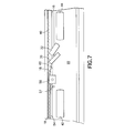
- the folding bar is positioned at an obtuse angle, preferably 135 to 170 degrees, relative to the side edge 16 with the flap 18 prior to folding as shown in FIG. 7 .
- the length of the folding bar should be selected to extend at least past the flap 18 when in a folded position (for example, as shown on the right side of the folding bar 64 in FIG.
- the folding bar 64 comprises a radiused rear side 66, preferably with a 1 ⁇ 2 to 3 ⁇ 4 inch radius, to facilitate folding of the flap 18 toward the back surface 22 of the panel 10, and can be made from any rigid material such as aluminum or other metals.
- a tension roller 32 is positioned downstream from the folding bar 64 and arranged to spin while in contact with the folded flap 19.
- the roller spins inwardly (counterclockwise as shown in FIG. 6 ) over the folded flap 19 at an obtuse angle, preferably 130 to 150 degrees, and most preferably about 135 degrees, relative to the side edge 16 with the flap 18 prior to folding as shown in FIG. 7 .
- the tension roller 32 similar to the drive wheels 42, 44, may be a single roller above the platform 38, or may be arranged as a top and bottom pair of rollers.
- the bottom tension roller is arranged to spin about an axis substantially perpendicular to the side edge 16 and the top tension roller is arranged to spin inwardly at the obtuse angle described above.
- a spring is provided to cause the rollers to bias toward each other and provide pressure of about 10 pounds to the folded flap 19 as it passes through the nip of the tension rollers. This arrangement pulls, stretches and squeezes the folded flap 19 to prevent wrinkles or voids in the sealed flap and the laminate cover 12 on the front surface 14 of the panel 10.
- Use of a pair of tension rollers with a straight roller on bottom and an angled roller on top as described above facilitates the pulling and stretching effect.
- Tension rollers sufficient for these purposes are non-marking rubber tread wheels of the type available, for example, from Albion Inc., Albion, Michigan or Bosch Rexroth AG, Germany.
- the tension roller 32 is tensioned by gravity, and no power is needed to cause the tension roller 32 to spin. Movement of the panel 10 through the apparatus 24 causes the tension roller 32 to spin.
- a stepper motor may be provided for powering the tension roller 32, which may be activated when the main power switch is turned on, or when either the first or second sensors 52, 57 sense a panel 10 in the edge wrapping apparatus 24.
- the second drive wheel 44 provides sufficient force to discharge the panel from the exit end 28 (shown in FIG. 5 ) of the edge wrapping apparatus.
- the edge wrapping apparatus can be situated next to an appropriate bin or table that collects the panels as they are discharged for subsequent processing or handling if desired.
- a second edge wrapping apparatus may be positioned adjacent a first edge wrapping apparatus to receive panel with one wrapped edge from the first edge wrapping apparatus, and having the components arranged such that a flap on a second edge of the panel may be folded, wrapped and sealed to the back surface of the panel.
- edge wrapping apparatus may be modified to permit wrapping of edges that are not straight by providing the series of guide rollers 40 with a curve, and could be modified to provide a complimentary and additional set of components on the opposite side of the apparatus to permit simultaneous wrapping, folding and sealing of a second flap.
- many modifications may be made to adapt a particular situation to the teachings of the invention without departing from the essential scope thereof. Therefore it is intended that the invention not be limited to the particular embodiment disclosed as the best mode contemplated for carrying out this invention.
Landscapes
- Engineering & Computer Science (AREA)
- Manufacturing & Machinery (AREA)
- Folding Of Thin Sheet-Like Materials, Special Discharging Devices, And Others (AREA)
- Basic Packing Technique (AREA)
Applications Claiming Priority (1)
| Application Number | Priority Date | Filing Date | Title |
|---|---|---|---|
| US13/189,890 US8453696B2 (en) | 2011-07-25 | 2011-07-25 | Automated edge wrapping of a panel |
Publications (3)
| Publication Number | Publication Date |
|---|---|
| EP2551090A2 true EP2551090A2 (de) | 2013-01-30 |
| EP2551090A3 EP2551090A3 (de) | 2013-10-23 |
| EP2551090B1 EP2551090B1 (de) | 2017-11-22 |
Family
ID=46578894
Family Applications (1)
| Application Number | Title | Priority Date | Filing Date |
|---|---|---|---|
| EP12177423.6A Not-in-force EP2551090B1 (de) | 2011-07-25 | 2012-07-23 | Automatische kantenumwicklung einer platte |
Country Status (3)
| Country | Link |
|---|---|
| US (1) | US8453696B2 (de) |
| EP (1) | EP2551090B1 (de) |
| CA (1) | CA2777847C (de) |
Families Citing this family (4)
| Publication number | Priority date | Publication date | Assignee | Title |
|---|---|---|---|---|
| US9162403B2 (en) | 2013-03-15 | 2015-10-20 | Davis-Standard, Llc | Apparatus for manufacturing and processing pre-stretch films having strips of increased thickness |
| US10766187B2 (en) * | 2015-05-15 | 2020-09-08 | Northwest Aerospace Technologies, Inc. | Laminate applicator |
| US11298870B2 (en) * | 2020-02-19 | 2022-04-12 | The Boeing Company | Methods for forming composite panels |
| JP7108767B1 (ja) | 2021-08-26 | 2022-07-28 | アイカ工業株式会社 | 連続式ポストフォーム加工装置 |
Family Cites Families (12)
| Publication number | Priority date | Publication date | Assignee | Title |
|---|---|---|---|---|
| US2970634A (en) * | 1955-07-13 | 1961-02-07 | Hantscho Co George | Method and apparatus for applying cover material to book cores and cases |
| US3389645A (en) | 1965-04-19 | 1968-06-25 | Fibreboard Corp | Apparatus and method for folding and sealing cartons |
| US3616077A (en) | 1969-06-20 | 1971-10-26 | Owens Illinois Inc | Corrugated paperboard edge sealing and slitting apparatus |
| US4248657A (en) | 1979-08-23 | 1981-02-03 | National Service Industries, Inc. | Apparatus for covering panels with sheet material |
| US4571916A (en) | 1983-12-05 | 1986-02-25 | Southern Tool Company | Secondary packaging machine |
| FR2646453B1 (fr) * | 1989-04-27 | 1993-05-07 | Saint Gobain Isover | Procede d'obtention en continu de panneaux revetus sur au moins deux faces adjacentes |
| US5520872A (en) * | 1993-08-09 | 1996-05-28 | Scherer; Philip G. | Method for hemming edges of stretch film |
| US6277463B1 (en) | 1998-08-28 | 2001-08-21 | Mcdonnell Douglas Corporation | Composite member having increased resistance to delamination and method of making same |
| WO2001056780A1 (en) * | 2000-02-01 | 2001-08-09 | Peter Danko | Method and apparatus for closing an open end of a product, & product formed thereby |
| US7303641B2 (en) | 2002-12-03 | 2007-12-04 | Hunter Douglas Inc. | Method for fabricating cellular structural panels |
| US7789986B2 (en) | 2006-03-06 | 2010-09-07 | Haworth, Inc. | Process and apparatus for edge wrapping upholstered articles |
| GB0611804D0 (en) | 2006-06-14 | 2006-07-26 | Airbus Uk Ltd | Improved aircraft component |
-
2011
- 2011-07-25 US US13/189,890 patent/US8453696B2/en not_active Expired - Fee Related
-
2012
- 2012-05-22 CA CA2777847A patent/CA2777847C/en active Active
- 2012-07-23 EP EP12177423.6A patent/EP2551090B1/de not_active Not-in-force
Non-Patent Citations (1)
| Title |
|---|
| None |
Also Published As
| Publication number | Publication date |
|---|---|
| US8453696B2 (en) | 2013-06-04 |
| CA2777847A1 (en) | 2013-01-25 |
| EP2551090A3 (de) | 2013-10-23 |
| US20130025773A1 (en) | 2013-01-31 |
| CA2777847C (en) | 2014-01-28 |
| EP2551090B1 (de) | 2017-11-22 |
Similar Documents
| Publication | Publication Date | Title |
|---|---|---|
| EP2551090B1 (de) | Automatische kantenumwicklung einer platte | |
| US7789986B2 (en) | Process and apparatus for edge wrapping upholstered articles | |
| US20070163207A1 (en) | Adhesive tape applying machine for use with a stretch wrapper | |
| JP4342829B2 (ja) | 光学フィルム貼付装置、方法及び基板 | |
| JPWO2012020610A1 (ja) | シート剥離装置および剥離方法ならびにシート貼付装置および貼付方法 | |
| KR101277326B1 (ko) | 유리기판 양면상 보호필름 부착장치 | |
| US20130081360A1 (en) | Corner protector placement system and method and related pallet wrapping system and method | |
| CN110053808B (zh) | 一种组合烟花顶招底招的自动包覆装置 | |
| KR20180018216A (ko) | 접착테이프자동부착장치 및 그를 포함하는 조립시스템 | |
| JPH03241100A (ja) | シート状の紙または厚紙を溶剤を用いない接着剤によって透明なフィルムと接合するためのプラスチック・コーティング機械 | |
| FI97460B (fi) | Menetelmä ja laite kappaleiden käärimiseksi | |
| CN214353108U (zh) | 一种板材封边机 | |
| US6662535B2 (en) | Apparatus for bagging material | |
| US8733416B2 (en) | Label applicator | |
| CN215512446U (zh) | 一种全自动紧固包装生产系统 | |
| JP3168708U (ja) | 接着剤の塗布装置 | |
| US7818949B2 (en) | Apparatus for bagging material | |
| JPH07329944A (ja) | シート貼付け装置及びシート貼付け方法 | |
| CN116714315B (zh) | 一种有底灭菌袋自动加工装置 | |
| JPH0740434A (ja) | シート貼付け方法及びシート貼付け装置 | |
| JP6507692B2 (ja) | ラベル貼付装置、およびラベル貼付装置を備えた包装装置 | |
| CN109648923A (zh) | 滤芯自动贴边装置贴边机构 | |
| CN112092461A (zh) | 一种折纸裁切装置 | |
| WO2026089903A1 (en) | Methods and apparatus for mitigating glass surface defects during lamination process | |
| CN121757430A (zh) | 一种无纺布产品覆膜包装设备 |
Legal Events
| Date | Code | Title | Description |
|---|---|---|---|
| PUAI | Public reference made under article 153(3) epc to a published international application that has entered the european phase |
Free format text: ORIGINAL CODE: 0009012 |
|
| AK | Designated contracting states |
Kind code of ref document: A2 Designated state(s): AL AT BE BG CH CY CZ DE DK EE ES FI FR GB GR HR HU IE IS IT LI LT LU LV MC MK MT NL NO PL PT RO RS SE SI SK SM TR |
|
| AX | Request for extension of the european patent |
Extension state: BA ME |
|
| PUAL | Search report despatched |
Free format text: ORIGINAL CODE: 0009013 |
|
| AK | Designated contracting states |
Kind code of ref document: A3 Designated state(s): AL AT BE BG CH CY CZ DE DK EE ES FI FR GB GR HR HU IE IS IT LI LT LU LV MC MK MT NL NO PL PT RO RS SE SI SK SM TR |
|
| AX | Request for extension of the european patent |
Extension state: BA ME |
|
| RIC1 | Information provided on ipc code assigned before grant |
Ipc: B44C 5/04 20060101ALI20130918BHEP Ipc: B29C 63/04 20060101AFI20130918BHEP |
|
| 17P | Request for examination filed |
Effective date: 20140423 |
|
| RBV | Designated contracting states (corrected) |
Designated state(s): AL AT BE BG CH CY CZ DE DK EE ES FI FR GB GR HR HU IE IS IT LI LT LU LV MC MK MT NL NO PL PT RO RS SE SI SK SM TR |
|
| 17Q | First examination report despatched |
Effective date: 20150720 |
|
| GRAP | Despatch of communication of intention to grant a patent |
Free format text: ORIGINAL CODE: EPIDOSNIGR1 |
|
| INTG | Intention to grant announced |
Effective date: 20151029 |
|
| INTC | Intention to grant announced (deleted) | ||
| GRAP | Despatch of communication of intention to grant a patent |
Free format text: ORIGINAL CODE: EPIDOSNIGR1 |
|
| INTG | Intention to grant announced |
Effective date: 20170602 |
|
| RIN1 | Information on inventor provided before grant (corrected) |
Inventor name: BOGGS, MICHAEL J. |
|
| GRAS | Grant fee paid |
Free format text: ORIGINAL CODE: EPIDOSNIGR3 |
|
| GRAA | (expected) grant |
Free format text: ORIGINAL CODE: 0009210 |
|
| AK | Designated contracting states |
Kind code of ref document: B1 Designated state(s): AL AT BE BG CH CY CZ DE DK EE ES FI FR GB GR HR HU IE IS IT LI LT LU LV MC MK MT NL NO PL PT RO RS SE SI SK SM TR |
|
| REG | Reference to a national code |
Ref country code: GB Ref legal event code: FG4D |
|
| REG | Reference to a national code |
Ref country code: CH Ref legal event code: EP |
|
| REG | Reference to a national code |
Ref country code: IE Ref legal event code: FG4D |
|
| REG | Reference to a national code |
Ref country code: AT Ref legal event code: REF Ref document number: 948001 Country of ref document: AT Kind code of ref document: T Effective date: 20171215 |
|
| REG | Reference to a national code |
Ref country code: DE Ref legal event code: R096 Ref document number: 602012040013 Country of ref document: DE |
|
| REG | Reference to a national code |
Ref country code: NL Ref legal event code: MP Effective date: 20171122 |
|
| REG | Reference to a national code |
Ref country code: LT Ref legal event code: MG4D |
|
| REG | Reference to a national code |
Ref country code: AT Ref legal event code: MK05 Ref document number: 948001 Country of ref document: AT Kind code of ref document: T Effective date: 20171122 |
|
| PG25 | Lapsed in a contracting state [announced via postgrant information from national office to epo] |
Ref country code: FI Free format text: LAPSE BECAUSE OF FAILURE TO SUBMIT A TRANSLATION OF THE DESCRIPTION OR TO PAY THE FEE WITHIN THE PRESCRIBED TIME-LIMIT Effective date: 20171122 Ref country code: NL Free format text: LAPSE BECAUSE OF FAILURE TO SUBMIT A TRANSLATION OF THE DESCRIPTION OR TO PAY THE FEE WITHIN THE PRESCRIBED TIME-LIMIT Effective date: 20171122 Ref country code: NO Free format text: LAPSE BECAUSE OF FAILURE TO SUBMIT A TRANSLATION OF THE DESCRIPTION OR TO PAY THE FEE WITHIN THE PRESCRIBED TIME-LIMIT Effective date: 20180222 Ref country code: SE Free format text: LAPSE BECAUSE OF FAILURE TO SUBMIT A TRANSLATION OF THE DESCRIPTION OR TO PAY THE FEE WITHIN THE PRESCRIBED TIME-LIMIT Effective date: 20171122 Ref country code: LT Free format text: LAPSE BECAUSE OF FAILURE TO SUBMIT A TRANSLATION OF THE DESCRIPTION OR TO PAY THE FEE WITHIN THE PRESCRIBED TIME-LIMIT Effective date: 20171122 Ref country code: ES Free format text: LAPSE BECAUSE OF FAILURE TO SUBMIT A TRANSLATION OF THE DESCRIPTION OR TO PAY THE FEE WITHIN THE PRESCRIBED TIME-LIMIT Effective date: 20171122 |
|
| PG25 | Lapsed in a contracting state [announced via postgrant information from national office to epo] |
Ref country code: BG Free format text: LAPSE BECAUSE OF FAILURE TO SUBMIT A TRANSLATION OF THE DESCRIPTION OR TO PAY THE FEE WITHIN THE PRESCRIBED TIME-LIMIT Effective date: 20180222 Ref country code: HR Free format text: LAPSE BECAUSE OF FAILURE TO SUBMIT A TRANSLATION OF THE DESCRIPTION OR TO PAY THE FEE WITHIN THE PRESCRIBED TIME-LIMIT Effective date: 20171122 Ref country code: LV Free format text: LAPSE BECAUSE OF FAILURE TO SUBMIT A TRANSLATION OF THE DESCRIPTION OR TO PAY THE FEE WITHIN THE PRESCRIBED TIME-LIMIT Effective date: 20171122 Ref country code: GR Free format text: LAPSE BECAUSE OF FAILURE TO SUBMIT A TRANSLATION OF THE DESCRIPTION OR TO PAY THE FEE WITHIN THE PRESCRIBED TIME-LIMIT Effective date: 20180223 Ref country code: RS Free format text: LAPSE BECAUSE OF FAILURE TO SUBMIT A TRANSLATION OF THE DESCRIPTION OR TO PAY THE FEE WITHIN THE PRESCRIBED TIME-LIMIT Effective date: 20171122 Ref country code: AT Free format text: LAPSE BECAUSE OF FAILURE TO SUBMIT A TRANSLATION OF THE DESCRIPTION OR TO PAY THE FEE WITHIN THE PRESCRIBED TIME-LIMIT Effective date: 20171122 |
|
| REG | Reference to a national code |
Ref country code: FR Ref legal event code: PLFP Year of fee payment: 7 |
|
| PG25 | Lapsed in a contracting state [announced via postgrant information from national office to epo] |
Ref country code: DK Free format text: LAPSE BECAUSE OF FAILURE TO SUBMIT A TRANSLATION OF THE DESCRIPTION OR TO PAY THE FEE WITHIN THE PRESCRIBED TIME-LIMIT Effective date: 20171122 Ref country code: SK Free format text: LAPSE BECAUSE OF FAILURE TO SUBMIT A TRANSLATION OF THE DESCRIPTION OR TO PAY THE FEE WITHIN THE PRESCRIBED TIME-LIMIT Effective date: 20171122 Ref country code: CY Free format text: LAPSE BECAUSE OF FAILURE TO SUBMIT A TRANSLATION OF THE DESCRIPTION OR TO PAY THE FEE WITHIN THE PRESCRIBED TIME-LIMIT Effective date: 20171122 Ref country code: CZ Free format text: LAPSE BECAUSE OF FAILURE TO SUBMIT A TRANSLATION OF THE DESCRIPTION OR TO PAY THE FEE WITHIN THE PRESCRIBED TIME-LIMIT Effective date: 20171122 Ref country code: EE Free format text: LAPSE BECAUSE OF FAILURE TO SUBMIT A TRANSLATION OF THE DESCRIPTION OR TO PAY THE FEE WITHIN THE PRESCRIBED TIME-LIMIT Effective date: 20171122 |
|
| REG | Reference to a national code |
Ref country code: DE Ref legal event code: R097 Ref document number: 602012040013 Country of ref document: DE |
|
| PG25 | Lapsed in a contracting state [announced via postgrant information from national office to epo] |
Ref country code: SM Free format text: LAPSE BECAUSE OF FAILURE TO SUBMIT A TRANSLATION OF THE DESCRIPTION OR TO PAY THE FEE WITHIN THE PRESCRIBED TIME-LIMIT Effective date: 20171122 Ref country code: PL Free format text: LAPSE BECAUSE OF FAILURE TO SUBMIT A TRANSLATION OF THE DESCRIPTION OR TO PAY THE FEE WITHIN THE PRESCRIBED TIME-LIMIT Effective date: 20171122 Ref country code: RO Free format text: LAPSE BECAUSE OF FAILURE TO SUBMIT A TRANSLATION OF THE DESCRIPTION OR TO PAY THE FEE WITHIN THE PRESCRIBED TIME-LIMIT Effective date: 20171122 Ref country code: IT Free format text: LAPSE BECAUSE OF FAILURE TO SUBMIT A TRANSLATION OF THE DESCRIPTION OR TO PAY THE FEE WITHIN THE PRESCRIBED TIME-LIMIT Effective date: 20171122 |
|
| PLBE | No opposition filed within time limit |
Free format text: ORIGINAL CODE: 0009261 |
|
| STAA | Information on the status of an ep patent application or granted ep patent |
Free format text: STATUS: NO OPPOSITION FILED WITHIN TIME LIMIT |
|
| 26N | No opposition filed |
Effective date: 20180823 |
|
| PG25 | Lapsed in a contracting state [announced via postgrant information from national office to epo] |
Ref country code: SI Free format text: LAPSE BECAUSE OF FAILURE TO SUBMIT A TRANSLATION OF THE DESCRIPTION OR TO PAY THE FEE WITHIN THE PRESCRIBED TIME-LIMIT Effective date: 20171122 |
|
| REG | Reference to a national code |
Ref country code: CH Ref legal event code: PL |
|
| PG25 | Lapsed in a contracting state [announced via postgrant information from national office to epo] |
Ref country code: MC Free format text: LAPSE BECAUSE OF FAILURE TO SUBMIT A TRANSLATION OF THE DESCRIPTION OR TO PAY THE FEE WITHIN THE PRESCRIBED TIME-LIMIT Effective date: 20171122 Ref country code: LU Free format text: LAPSE BECAUSE OF NON-PAYMENT OF DUE FEES Effective date: 20180723 |
|
| REG | Reference to a national code |
Ref country code: BE Ref legal event code: MM Effective date: 20180731 |
|
| REG | Reference to a national code |
Ref country code: IE Ref legal event code: MM4A |
|
| PG25 | Lapsed in a contracting state [announced via postgrant information from national office to epo] |
Ref country code: IE Free format text: LAPSE BECAUSE OF NON-PAYMENT OF DUE FEES Effective date: 20180723 Ref country code: CH Free format text: LAPSE BECAUSE OF NON-PAYMENT OF DUE FEES Effective date: 20180731 Ref country code: LI Free format text: LAPSE BECAUSE OF NON-PAYMENT OF DUE FEES Effective date: 20180731 |
|
| PG25 | Lapsed in a contracting state [announced via postgrant information from national office to epo] |
Ref country code: BE Free format text: LAPSE BECAUSE OF NON-PAYMENT OF DUE FEES Effective date: 20180731 |
|
| PG25 | Lapsed in a contracting state [announced via postgrant information from national office to epo] |
Ref country code: MT Free format text: LAPSE BECAUSE OF NON-PAYMENT OF DUE FEES Effective date: 20180723 |
|
| PG25 | Lapsed in a contracting state [announced via postgrant information from national office to epo] |
Ref country code: TR Free format text: LAPSE BECAUSE OF FAILURE TO SUBMIT A TRANSLATION OF THE DESCRIPTION OR TO PAY THE FEE WITHIN THE PRESCRIBED TIME-LIMIT Effective date: 20171122 |
|
| PG25 | Lapsed in a contracting state [announced via postgrant information from national office to epo] |
Ref country code: PT Free format text: LAPSE BECAUSE OF FAILURE TO SUBMIT A TRANSLATION OF THE DESCRIPTION OR TO PAY THE FEE WITHIN THE PRESCRIBED TIME-LIMIT Effective date: 20171122 Ref country code: HU Free format text: LAPSE BECAUSE OF FAILURE TO SUBMIT A TRANSLATION OF THE DESCRIPTION OR TO PAY THE FEE WITHIN THE PRESCRIBED TIME-LIMIT; INVALID AB INITIO Effective date: 20120723 |
|
| PG25 | Lapsed in a contracting state [announced via postgrant information from national office to epo] |
Ref country code: MK Free format text: LAPSE BECAUSE OF NON-PAYMENT OF DUE FEES Effective date: 20171122 |
|
| PG25 | Lapsed in a contracting state [announced via postgrant information from national office to epo] |
Ref country code: AL Free format text: LAPSE BECAUSE OF FAILURE TO SUBMIT A TRANSLATION OF THE DESCRIPTION OR TO PAY THE FEE WITHIN THE PRESCRIBED TIME-LIMIT Effective date: 20171122 Ref country code: IS Free format text: LAPSE BECAUSE OF FAILURE TO SUBMIT A TRANSLATION OF THE DESCRIPTION OR TO PAY THE FEE WITHIN THE PRESCRIBED TIME-LIMIT Effective date: 20180322 |
|
| P01 | Opt-out of the competence of the unified patent court (upc) registered |
Effective date: 20230516 |
|
| PGFP | Annual fee paid to national office [announced via postgrant information from national office to epo] |
Ref country code: DE Payment date: 20240729 Year of fee payment: 13 |
|
| PGFP | Annual fee paid to national office [announced via postgrant information from national office to epo] |
Ref country code: GB Payment date: 20240729 Year of fee payment: 13 |
|
| PGFP | Annual fee paid to national office [announced via postgrant information from national office to epo] |
Ref country code: FR Payment date: 20240725 Year of fee payment: 13 |
|
| REG | Reference to a national code |
Ref country code: DE Ref legal event code: R119 Ref document number: 602012040013 Country of ref document: DE |
|
| GBPC | Gb: european patent ceased through non-payment of renewal fee |
Effective date: 20250723 |
|
| PG25 | Lapsed in a contracting state [announced via postgrant information from national office to epo] |
Ref country code: GB Free format text: LAPSE BECAUSE OF NON-PAYMENT OF DUE FEES Effective date: 20250723 |
|
| PG25 | Lapsed in a contracting state [announced via postgrant information from national office to epo] |
Ref country code: DE Free format text: LAPSE BECAUSE OF NON-PAYMENT OF DUE FEES Effective date: 20260203 |
|
| PG25 | Lapsed in a contracting state [announced via postgrant information from national office to epo] |
Ref country code: FR Free format text: LAPSE BECAUSE OF NON-PAYMENT OF DUE FEES Effective date: 20250731 |