EP2551069A2 - Roboter und Herstellungsverfahren dafür - Google Patents
Roboter und Herstellungsverfahren dafür Download PDFInfo
- Publication number
- EP2551069A2 EP2551069A2 EP12156110A EP12156110A EP2551069A2 EP 2551069 A2 EP2551069 A2 EP 2551069A2 EP 12156110 A EP12156110 A EP 12156110A EP 12156110 A EP12156110 A EP 12156110A EP 2551069 A2 EP2551069 A2 EP 2551069A2
- Authority
- EP
- European Patent Office
- Prior art keywords
- speed reducer
- motor
- joint
- articulated arm
- robot
- Prior art date
- Legal status (The legal status is an assumption and is not a legal conclusion. Google has not performed a legal analysis and makes no representation as to the accuracy of the status listed.)
- Withdrawn
Links
Images
Classifications
-
- B—PERFORMING OPERATIONS; TRANSPORTING
- B25—HAND TOOLS; PORTABLE POWER-DRIVEN TOOLS; MANIPULATORS
- B25J—MANIPULATORS; CHAMBERS PROVIDED WITH MANIPULATION DEVICES
- B25J9/00—Program-controlled manipulators
- B25J9/16—Program controls
- B25J9/1628—Program controls characterised by the control loop
- B25J9/1638—Program controls characterised by the control loop compensation for arm bending/inertia, pay load weight/inertia
-
- B—PERFORMING OPERATIONS; TRANSPORTING
- B25—HAND TOOLS; PORTABLE POWER-DRIVEN TOOLS; MANIPULATORS
- B25J—MANIPULATORS; CHAMBERS PROVIDED WITH MANIPULATION DEVICES
- B25J19/00—Accessories fitted to manipulators, e.g. for monitoring, for viewing; Safety devices combined with or specially adapted for use in connection with manipulators
- B25J19/007—Means or methods for designing or fabricating manipulators
-
- G—PHYSICS
- G05—CONTROLLING; REGULATING
- G05B—CONTROL OR REGULATING SYSTEMS IN GENERAL; FUNCTIONAL ELEMENTS OF SUCH SYSTEMS; MONITORING OR TESTING ARRANGEMENTS FOR SUCH SYSTEMS OR ELEMENTS
- G05B2219/00—Program-control systems
- G05B2219/30—Nc systems
- G05B2219/39—Robotics, robotics to robotics hand
- G05B2219/39176—Compensation deflection arm
-
- Y—GENERAL TAGGING OF NEW TECHNOLOGICAL DEVELOPMENTS; GENERAL TAGGING OF CROSS-SECTIONAL TECHNOLOGIES SPANNING OVER SEVERAL SECTIONS OF THE IPC; TECHNICAL SUBJECTS COVERED BY FORMER USPC CROSS-REFERENCE ART COLLECTIONS [XRACs] AND DIGESTS
- Y10—TECHNICAL SUBJECTS COVERED BY FORMER USPC
- Y10T—TECHNICAL SUBJECTS COVERED BY FORMER US CLASSIFICATION
- Y10T74/00—Machine element or mechanism
- Y10T74/20—Control lever and linkage systems
- Y10T74/20207—Multiple controlling elements for single controlled element
- Y10T74/20305—Robotic arm
- Y10T74/20329—Joint between elements
Definitions
- the embodiment discussed herein is directed to a robot and a method for manufacturing the same.
- a conventional robot which includes an articulated arm and performs various operations by using an end effector of a terminal moving part of the articulated arm.
- an end effector for example, when a laser head or the like is used as an end effector, the robot can perform operations such as for example laser cutting and laser welding on a target object.
- the operation using the laser head or the like is generally performed by controlling the articulated arm to raise a precision of a "trajectory" such as for example a straight line and a circular arc drawn by the laser.
- a "trajectory" such as for example a straight line and a circular arc drawn by the laser.
- control gain a control target value from an error between the detected actual position and posture of a articulated arm and the targeted position and posture and correcting the position and posture of the articulated arm by using the control gain.
- the conventional technique has a problem in that increasing a control gain, for example, to obtain a high-accuracy trajectory at a high moving speed causes a vibration of the arm and thus the precision of the trajectory may be degraded.
- the conventional art does not satisfy both of the high precision of a trajectory and the speed-up of a moving speed.
- An aspect of an embodiment has been achieved in view of the above problems, and an object of the embodiment is to provide a robot and a method for manufacturing the same that can satisfy both of the high precision of a trajectory and the speed-up of a moving speed.
- a robot includes: an articulated arm; and a speed reducer that is provided in a joint of the articulated arm.
- the articulated arm performs a multi-axis operation.
- the speed reducer has rigidity for which an acquisition value obtained by acquiring a deflection amount of a predetermined representative position at the articulated arm for each dimension of a three-dimensional coordinate system is not more than a threshold corresponding to a target precision of the articulated arm.
- both of the high precision of a trajectory and the speed-up of a moving speed can be satisfied.
- FIG. 1 is a side view illustrating the configuration of a robot according to an embodiment
- FIG. 2 is a pattern diagram illustrating a movement of an articulated arm
- FIG. 3A is a diagram illustrating an example of a threshold for each direction component of an amount of deflection at a point P;
- FIG. 3B is a diagram illustrating rigidity of each speed reducer for each direction component
- FIG. 3C is a diagram illustrating an example of a selection condition of each motor
- FIG. 4A is the first diagram illustrating a selection sequence of each speed reducer and motor
- FIG. 4B is the second diagram illustrating a selection sequence of each speed reducer and motor
- FIG. 4C is the third diagram illustrating a selection sequence of each speed reducer and motor
- FIG. 5 is a diagram illustrating a correspondence relationship between an angle of deflection and a target precision of the articulated arm
- FIG. 6A is a diagram illustrating a first offset of a third arm part
- FIG. 6B is a diagram illustrating a second offset of the third arm part.
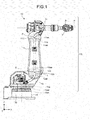
- FIG. 1 is a side view illustrating the configuration of a robot 10 according to the embodiment.
- a three-dimensional rectangular coordinate system that has Z-axis of which the positive direction is a vertically upward direction is illustrated in FIG. 1 .
- the rectangular coordinate system can be also illustrated in other drawings that are used for the following explanations.
- the robot 10 includes a first arm part 11, a second arm part 12, a third arm part 13, and a base 14.
- the bottom end of the first arm part 11 is supported by the second arm part 12 and its leading end supports an end effector (not illustrated).
- the bottom end of the second arm part 12 is supported by the third arm part 13 and its leading end supports the first arm part 11.
- the bottom end of the third arm part 13 is supported by the base 14 and its leading end supports the second arm part 12.
- the base 14 is fixed on an installation surface such as a floor.
- first arm part 11 and the second arm part 12 are connected via a first joint 11a.
- the first joint 11a is provided with a first speed reducer 11aa and a first motor 11ab.
- the first arm part 11 rotates around the U-axis parallel to Y-axis in accordance with the drive of the first speed reducer 11aa and the first motor 11ab.
- the second arm part 12 and the third arm part 13 are connected via a second joint 12a.
- the second joint 12a is provided with a second speed reducer 12aa and a second motor 12ab.
- the second arm part 12 rotates around the L-axis parallel to Y-axis in accordance with the drive of the second speed reducer 12aa and the second motor 12ab.
- the third arm part 13 and the base 14 are connected via a third joint 13a.
- the third joint 13a is provided with a third speed reducer 13aa and a third motor 13ab.
- the third arm part 13 rotates around the S-axis parallel to Z-axis in accordance with the drive of the third speed reducer 13aa and the third motor 13ab.
- first speed reducer 11aa, the second speed reducer 12aa, the third speed reducer 13aa, the first motor 11ab, the second motor 12ab, and the third motor 13ab are simply illustrated in FIG. 1 . These can be omitted in other drawings that are used for the following explanations.
- first speed reducer 11aa, the second speed reducer 12aa, and the third speed reducer 13aa may be collectively referred to as "each speed reducer", and the first motor 11ab, the second motor 12ab, and the third motor 13ab may be collectively referred to as "each motor”.
- the robot 10 includes a so-called articulated arm 15, of which arm parts are connected via joints to perform multi-axis operations.
- the articulated arm 15 further has joints such as a joint that rotates around the R-axis parallel to X-axis and a joint that rotates around the B-axis parallel to Y-axis.
- the present embodiment is mainly explained by using the first joint 11a, the second joint 12a, and the third joint 13a.
- a point P is particularly defined as an intersection point of the R-axis and the B-axis. It is assumed that this point P indicates a predetermined representative position of the articulated arm 15 of the robot 10.
- the robot 10 selects and includes the first speed reducer 11aa, the second speed reducer 12aa, and the third speed reducer 13aa that have rigidity for which an amount of deflection of each dimension of a three-dimensional coordinate system for the point P is not more than a threshold corresponding to a target precision of the articulated arm 15.
- the robot 10 selects and includes the first motor 11ab, the second motor 12ab, and the third motor 13ab, which respectively correspond to the first speed reducer 11aa, the second speed reducer 12aa, and the third speed reducer 13aa that are selected.
- the joints of the articulated arm 15 may respectively include a mounting part 110, a mounting part 120, and a mounting part 130 of which each can allow only the corresponding speed reducer and motor to be replaced.
- the amount of deflection can be easily adjusted only by selecting each speed reducer and motor without replacing each arm part. In other words, a time-consuming dedicated design can be omitted.
- FIG. 1 only simply illustrates the mounting part 110, the mounting part 120, and the mounting part 130 and thus does not limit their configurations.
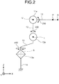
- FIG. 2 is a pattern diagram illustrating a movement of the articulated arm 15.
- a posture of the articulated arm 15 is referred to as a "reference posture" when the first arm part 11 is maintained parallel to X-axis and the second arm part 12 and both ends of the third arm part 13 are maintained parallel to Z-axis as illustrated in FIG. 2 .
- the first joint 11a rotates the first arm part 11, of which the leading end supports an end effector E, around the U-axis (see an arrow 200 of FIG. 2 ).
- the second joint 12a rotates the second arm part 12 around the L-axis (see an arrow 300 of FIG. 2 ).
- the third joint 13a rotates the third arm part 13 around the S-axis (see an arrow 400 of FIG. 2 ).
- the first speed reducer 11aa provided in the first joint 11a, the second speed reducer 12aa provided in the second joint 12a, and the third speed reducer 13aa provided in the third joint 13a are conventionally selected in many cases in serious consideration of rigidity against gravitational moment.
- an amount of deflection at the point P is mainly analyzed for a Z-direction component of FIG. 2 .
- the selection of each speed reducer is performed in serious consideration of rigidity against the Z direction.
- each speed reducer is selected in consideration of rigidity against a shake of the rotating axis when a moment is added from a direction indicated by the rotating axis in addition to the Z direction.
- the selection method of each speed reducer and motor of the robot 10 acquires and analyzes deflection amounts at the point P with respect to three directional components of three dimensions in addition to the Z direction component.
- Each speed reducer is selected to have rigidity for which each of the acquired three directional-component deflection amounts is not more than a threshold corresponding to the target precision of the articulated arm 15.
- the rigidity particularly includes “moment rigidity” that is rigidity against a shake of each rotating axis of the first joint 11a, the second joint 12a, and the third joint 13a and “torsional rigidity” that is rigidity against a torsion of a rotation direction centering on each rotating axis.
- load inertia When a load-side inertia moment is defined as “load inertia” and a motor-side inertia moment is defined as “motor inertia”, it is assumed that each motor is selected, which has substantially the same motor inertia as load inertia when each selected speed reducer is included as a load.
- the second joint 12a rotates the second arm part 12 toward X-axis when being viewed from the reference posture, it may be said that the L-axis that is a rotating axis for the rotation is largely concerned with deflection for the X direction of the articulated arm 15.
- the third joint 13a rotates the third arm part 13 toward Y-axis when being viewed from the reference posture, it may be said that the S-axis that is a rotating axis for the rotation is largely concerned with deflection for the Y direction of the articulated arm 15.
- a relation between the rotating axes and XYZ directions influences a target precision of an angle of deflection to be described below. This point is described below with reference to FIG. 5 .
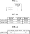
- FIG. 3A is a diagram illustrating an example of an upper-limit threshold for each direction component of a deflection amount at the point P.
- the robot 10 according to the embodiment has the S-axis that indicates the Z direction and the axes U and L that are a rotating axis indicating the Y direction. For this reason, the selection method of each speed reducer of the robot 10 according to the embodiment employs the Y direction and the Z direction as a reference direction.
- the Y direction and the Z direction will be centrally explained.
- the selection method of each speed reducer and motor of the robot 10 sets an upper-limit threshold of a deflection amount at the point P for each direction component.
- a deflection amount is indicated by an angle of deflection (see “deg” of FIG. 3A ) that is a displacement angle from a predetermined reference position.
- an upper-limit threshold in the Y direction of the angle of deflection is "a”
- an upper-limit threshold in the Z direction is "b”.
- each speed reducer is selected on the basis of whether a speed reducer has rigidity by which a deflection angle at the point P is kept in a tolerance of a deflection angle determined by the upper-limit threshold "a" and the upper-limit threshold "b".
- the tolerance may be referred to as a "target precision”.
- a deflection angle of the point P is kept in a tolerance (that is to say, a deflection angle is not more than the upper-limit thresholds "a" and "b") may be described as "a target precision is satisfied”.
- FIG. 3B is a diagram illustrating rigidity of each speed reducer for each direction component.
- the first speed reducer 11aa provided in the first joint 11a uses the U-axis indicating the Y direction as a rotating axis, moment rigidity is considered for the Y direction and torsional rigidity (specifically, spring constant) is considered for the Z direction to select a speed reducer that can satisfy a target precision.
- this point is similarly applied to the second speed reducer 12aa of the second joint 12a (see FIG. 1 ) of which the rotating axis is the L-axis indicating the Y direction.
- the third speed reducer 13aa provided in the third joint 13a uses the S-axis indicating the Z direction as a rotating axis, torsional rigidity is considered for the Y direction and moment rigidity is considered for the Z direction to select a speed reducer that can satisfy a target precision.
- the determination of whether a target precision can be satisfied may not depend on a specific method. Therefore, the determination may use a simulation method or may use an actual measurement value determination method.
- FIG. 3C is a diagram illustrating an example of a selection condition of each motor.
- each motor can employ an inertia ratio that is a ratio between motor inertia and load inertia as one of selection conditions.
- FIG. 3C illustrates that the inertia ratios of the first motor 11ab provided in the first joint 11a (see FIG. 1 ), the second motor 12ab provided in the second joint 12a (see FIG. 1 ), and the third motor 13ab provided in the third joint 13a (see FIG. 1 ) are "1:1".
- each motor is selected of which the inertia ratio is close to "1:1" as much as possible, that is to say, the motor inertia is substantially the same as load inertia.
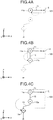
- FIG. 4A is the first diagram illustrating a selection sequence of each speed reducer and motor.
- FIG. 4B is the second diagram illustrating a selection sequence of each speed reducer and motor.
- FIG. 4C is the third diagram illustrating a selection sequence of each speed reducer and motor.
- the first speed reducer 11aa and the first motor 11ab of the first joint 11a become a target for selection.
- the first speed reducer 11aa is selected prior to the first motor 11ab.
- the selection of the first speed reducer 11aa is performed by selecting a speed reducer that has the moment rigidity for the Y direction and the torsional rigidity for the Z direction, which satisfy a target precision.
- the first motor 11ab is selected in accordance with the selected first speed reducer 11aa. As already described with reference to FIG. 3C , the selection of the first motor 11ab is performed by selecting a motor that has substantially the same motor inertia as load inertia.
- loads of the first motor 11ab are the end effector E and the first arm part 11, which are surrounded by a dotted rectangle 101 of FIG. 4A , and the first speed reducer 11aa that is previously selected.
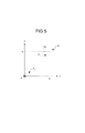
- FIG. 5 is a diagram illustrating a correspondence relationship between a deflection angle and a target precision of the articulated arm 15.
- FIG. 5 illustrates a three-dimensional coordinate system of XYZ axes when being viewed from the positive direction of X-axis.
- two-dimensional components of YZ axes are mainly explained herein.
- the first set is referred to as the first candidate
- the second set is referred to as the second candidate
- the third set is referred to as the third candidate.
- a deflection angle at the point P acquired by using the first candidate is P 1 .
- a deflection angle using the second candidate is P 2 and a deflection angle using the third candidate is P 3 .
- the deflection angles are already acquired by a simulation, an actual measurement, or the like.
- a predetermined reference position of the deflection angle is the intersection point of XYZ axes.
- the target precision of the deflection angle can be indicated by a range that is surrounded by a dotted line 104 and YZ axes.
- the first candidate is excluded from the final selection. If the combination of the selected the first speed reducer 11aa and the first motor 11ab is only the first candidate, the explanation is returned to the procedure explained by using FIG. 4A .
- any of the second and third candidates can be the final selection target.
- the deflection angle P 2 of the second candidate is relatively far away from the predetermined reference position and the deflection angle P 3 of the third candidate is relatively close to the predetermined reference position.
- a method to be explained next may be used, for example.
- the U-axis (see Fig. 2 ) that is a rotating axis of the first joint 11a is largely concerned with the deflection for the Z direction of the articulated arm 15.
- any of the second and third candidates can be selected in accordance with the related degree.
- the second candidate can be selected even if the deflection angle P 2 is far away from the predetermined reference position.
- the third candidate indicating the deflection angle P 3 closer to the predetermined reference position is selected as illustrated in FIG. 5 .
- the high precision of a trajectory of the articulated arm 15 can be achieved by verifying the effectiveness of the selected the first speed reducer 11aa and the first motor 11ab.
- the verification method can be applied to the case where "the second speed reducer 12aa and the second motor 12ab" or "the third speed reducer 13aa and the third motor 13ab" are selected in addition to the case where the first speed reducer 11aa and the first motor 11ab are selected. Furthermore, the verification method can be applied to comprehensive verification when all speed reducers and motors are together selected.
- the next selection target is the second speed reducer 12aa and the second motor 12ab of the second joint 12a illustrated in FIG. 4B .
- the second speed reducer 12aa is selected prior to the second motor 12ab.
- the selection of the second speed reducer 12aa is performed by selecting a speed reducer that has the moment rigidity for the Y direction and the torsional rigidity for the Z direction, which satisfy the target precision.
- the second motor 12ab is selected in accordance with the selected the second speed reducer 12aa.
- the selection of the second motor 12ab is performed by selecting a motor that has substantially the same motor inertia as load inertia.
- loads of the second motor 12ab are the end effector E, the first arm part 11, the first joint 11a, and the second arm part 12, which are surrounded by a dotted rectangle 102 of FIG. 4B , and the second speed reducer 12aa that is previously selected.
- the verification of the effectiveness is performed on the selected the second speed reducer 12aa and the second motor 12ab similarly to the case of the first speed reducer 11aa and the first motor 11ab (see FIG. 5 ).
- the verification of the effectiveness is also performed on the third speed reducer 13aa and the third motor 13ab of the third joint 13a. As illustrated in FIG. 4C , the third speed reducer 13aa and the third motor 13ab of the third joint 13a become the next selection target. Among them, the third speed reducer 13aa is selected prior to the third motor 13ab.
- the selection of the third speed reducer 13aa is performed by selecting a speed reducer that has the torsional rigidity for the Y direction and the moment rigidity for the Z direction that satisfy the target precision (see FIG. 3B ).
- the third motor 13ab is selected in accordance with the selected third speed reducer 13aa.
- the selection of the third motor 13ab is also performed by selecting a motor that has substantially the same motor inertia as load inertia (see FIG. 3C ).
- loads of the third motor 13ab are the end effector E, the first arm part 11, the first joint 11a, the second arm part 12, the second joint 12a, and the third arm part 13, which are surrounded by a dotted rectangle 103 of FIG. 4C , and the third speed reducer 13aa that is previously selected.
- speed reducer and motor are selected for each joint and effectiveness is verified in each case.
- the embodiment is not limited to this method.
- speed reducers and motors may be all selected in sequence from the leading end of the articulated arm 15, and then the comprehensive verification of effectiveness may be finally performed.
- each arm part can also result in the lightweighting of each speed reducer and motor and can easily result in the reduction of load inertia.
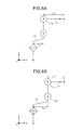
- FIG. 6A is a diagram illustrating a first offset of the third arm part 13.
- FIG. 6B is a diagram illustrating a second offset of the third arm part 13.
- the arm length of the first arm part 11 is "L1" and the offset of the third arm part 13 is "L2".
- L1 the arm length of the first arm part 11
- L2 the offset of the third arm part 13
- the arm length of the first arm part 11 becomes an arm length L1' shorter than the arm length L1 in accordance with the lightweighting.
- the movable range of the articulated arm 15 is narrowed by shortening of the first arm part 11.
- the movable range of the articulated arm 15 can be maintained within a predetermined movable range by elongating the offset of the third arm part 13 to an offset L2' longer than an offset L2, for example.
- the robot according to the embodiment includes an articulated arm and a speed reducer provided in each joint of the articulated arm.
- the speed reducer has rigidity for which an acquisition value obtained by acquiring a deflection amount of a predetermined representative position at the articulated arm for each dimension of a three-dimensional coordinate system is not more than a threshold corresponding to a target precision of the articulated arm.
- the robot according to the embodiment further includes a motor provided in each joint. When the speed reducer is included as a load, the motor has substantially the same motor inertia as load inertia.
- the robot according to the embodiment can satisfy both of the high precision of a trajectory and the speed-up of a moving speed.
- each motor has substantially the same motor inertia as load inertia when each selected speed reducer is selected as a load.
- the present embodiment is not limited to this.
- each motor may be selected in such a manner that the motor has substantially the same motor inertia as load inertia in which a speed reducer is not included as a load.
- a deflection amount of a predetermined representative position at the articulated arm is analyzed for each dimension of a three-dimensional coordinate system.
- the present embodiment is not limited to this.
- a deflection amount may be analyzed for many dimensions more than three dimensions.
- a deflection amount is expressed by a deflection angle that is a displacement angle away from a predetermined reference position.
- a deflection amount may be based on a distance or the like away from a predetermined reference position.
Landscapes
- Engineering & Computer Science (AREA)
- Robotics (AREA)
- Mechanical Engineering (AREA)
- Manipulator (AREA)
Applications Claiming Priority (1)
| Application Number | Priority Date | Filing Date | Title |
|---|---|---|---|
| JP2011163664A JP5482742B2 (ja) | 2011-07-26 | 2011-07-26 | ロボットの製造方法 |
Publications (2)
| Publication Number | Publication Date |
|---|---|
| EP2551069A2 true EP2551069A2 (de) | 2013-01-30 |
| EP2551069A3 EP2551069A3 (de) | 2013-06-19 |
Family
ID=45656137
Family Applications (1)
| Application Number | Title | Priority Date | Filing Date |
|---|---|---|---|
| EP12156110.4A Withdrawn EP2551069A3 (de) | 2011-07-26 | 2012-02-20 | Roboter und Herstellungsverfahren dafür |
Country Status (4)
| Country | Link |
|---|---|
| US (1) | US20130025399A1 (de) |
| EP (1) | EP2551069A3 (de) |
| JP (1) | JP5482742B2 (de) |
| CN (1) | CN102896629A (de) |
Cited By (2)
| Publication number | Priority date | Publication date | Assignee | Title |
|---|---|---|---|---|
| CN110666840A (zh) * | 2019-10-16 | 2020-01-10 | 金陵科技学院 | 一种工业机器人综合性能指标设计评价方法 |
| US10953540B2 (en) | 2017-01-17 | 2021-03-23 | Fanuc Corporation | Robot control device |
Families Citing this family (6)
| Publication number | Priority date | Publication date | Assignee | Title |
|---|---|---|---|---|
| JP5975129B1 (ja) | 2015-03-02 | 2016-08-23 | 株式会社安川電機 | ロボット |
| US9744665B1 (en) * | 2016-01-27 | 2017-08-29 | X Development Llc | Optimization of observer robot locations |
| CN107479474A (zh) * | 2017-09-22 | 2017-12-15 | 重庆鲁班机器人技术研究院有限公司 | 工业机器人质量评价方法及装置 |
| JP6934640B2 (ja) * | 2018-04-20 | 2021-09-15 | パナソニックIpマネジメント株式会社 | ロボットの制御方法 |
| CN110181505B (zh) * | 2019-04-22 | 2021-09-07 | 珠海格力智能装备有限公司 | 机器人的减速机确定的方法及机器人 |
| CN113905853B (zh) * | 2019-06-04 | 2024-03-08 | 松下知识产权经营株式会社 | 机器人的控制方法 |
Citations (1)
| Publication number | Priority date | Publication date | Assignee | Title |
|---|---|---|---|---|
| JP2003071760A (ja) | 2001-08-31 | 2003-03-12 | Ricoh Co Ltd | 組立ロボット |
Family Cites Families (13)
| Publication number | Priority date | Publication date | Assignee | Title |
|---|---|---|---|---|
| US4973215A (en) * | 1986-02-18 | 1990-11-27 | Robotics Research Corporation | Industrial robot with servo |
| JPH05253882A (ja) * | 1992-03-10 | 1993-10-05 | Hitachi Metals Ltd | 3自由度の手首を持つロボット |
| DE69317574T2 (de) * | 1993-09-01 | 1998-07-09 | Yaskawa Denki Kitakyushu Kk | Gelenkroboter |
| IT1272083B (it) * | 1993-12-17 | 1997-06-11 | Comau Spa | Robot industriale con gruppi riduttori integrati. |
| JPH0871963A (ja) * | 1994-08-31 | 1996-03-19 | Toshiba Corp | 産業用ロボット |
| CN1361456A (zh) * | 2000-12-27 | 2002-07-31 | 中国科学院沈阳自动化研究所 | 一种基于传感器的谐波驱动单元控制方法及专用实现装置 |
| CN2465893Y (zh) * | 2001-01-20 | 2001-12-19 | 中国科学院沈阳自动化研究所 | 垂直关节型机器人操作机 |
| JP3808321B2 (ja) * | 2001-04-16 | 2006-08-09 | ファナック株式会社 | ロボット制御装置 |
| TWI273009B (en) * | 2003-01-21 | 2007-02-11 | Yaskawa Electric Corp | Speed reducer for industrial robot |
| JPWO2009069389A1 (ja) * | 2007-11-26 | 2011-04-07 | 株式会社安川電機 | 垂直多関節形ロボット |
| JP5157498B2 (ja) * | 2008-02-05 | 2013-03-06 | 株式会社安川電機 | 産業用ロボットおよび産業用ロボットの手首機構 |
| JP5413036B2 (ja) * | 2009-08-04 | 2014-02-12 | 株式会社安川電機 | モータ制御装置及びモータ制御システム |
| JP5919142B2 (ja) * | 2012-08-31 | 2016-05-18 | 本田技研工業株式会社 | 駆動装置 |
-
2011
- 2011-07-26 JP JP2011163664A patent/JP5482742B2/ja not_active Expired - Fee Related
-
2012
- 2012-02-08 US US13/368,338 patent/US20130025399A1/en not_active Abandoned
- 2012-02-16 CN CN2012100356591A patent/CN102896629A/zh active Pending
- 2012-02-20 EP EP12156110.4A patent/EP2551069A3/de not_active Withdrawn
Patent Citations (1)
| Publication number | Priority date | Publication date | Assignee | Title |
|---|---|---|---|---|
| JP2003071760A (ja) | 2001-08-31 | 2003-03-12 | Ricoh Co Ltd | 組立ロボット |
Cited By (2)
| Publication number | Priority date | Publication date | Assignee | Title |
|---|---|---|---|---|
| US10953540B2 (en) | 2017-01-17 | 2021-03-23 | Fanuc Corporation | Robot control device |
| CN110666840A (zh) * | 2019-10-16 | 2020-01-10 | 金陵科技学院 | 一种工业机器人综合性能指标设计评价方法 |
Also Published As
| Publication number | Publication date |
|---|---|
| JP2013027939A (ja) | 2013-02-07 |
| EP2551069A3 (de) | 2013-06-19 |
| JP5482742B2 (ja) | 2014-05-07 |
| CN102896629A (zh) | 2013-01-30 |
| US20130025399A1 (en) | 2013-01-31 |
Similar Documents
| Publication | Publication Date | Title |
|---|---|---|
| EP2551069A2 (de) | Roboter und Herstellungsverfahren dafür | |
| JP6351293B2 (ja) | ロボットシステム、および物品の製造方法 | |
| CN108422420B (zh) | 具有学习控制功能的机器人系统以及学习控制方法 | |
| US8406921B2 (en) | Method and device for controlling a manipulator | |
| JP5531996B2 (ja) | 6軸ロボットの軸間オフセット検出方法 | |
| EP2404712A1 (de) | Roboter mit zwei Armen und Verfahren zum Steuern eines Roboters mit zwei Armen | |
| JP5786550B2 (ja) | 6軸ロボットの軸間オフセット検出方法 | |
| EP3351355B1 (de) | Vorrichtung und verfahren zur positionierung eines bearbeitungswerkzeugs | |
| JP2010253676A (ja) | マニピュレータの制御方法および制御装置 | |
| CN107635730A (zh) | 机器人系统 | |
| JP7547940B2 (ja) | ロボットの制御方法 | |
| JP2013000833A (ja) | ロボットの故障検出方法、ロボット | |
| US9676100B2 (en) | Control apparatus of robot, robot, and program thereof | |
| JP2019055440A (ja) | ロボットシステムおよびワークの製造方法 | |
| JP7165951B2 (ja) | ロボットの制御方法 | |
| CN112601640A (zh) | 机器人调节 | |
| JP6697544B2 (ja) | 最適化装置及びそれを備えた垂直型多関節ロボット | |
| WO2020255312A1 (ja) | ロボットの動作調整装置、動作制御システムおよびロボットシステム | |
| JP6057284B2 (ja) | 多関節ロボット及び半導体ウェハ搬送装置 | |
| US12005583B2 (en) | Robotic system for moving a payload with minimal payload sway and increased positioning accuracy | |
| CN116887953B (zh) | 弹簧常数校正装置及弹簧常数校正方法以及记录介质 | |
| JP2020157459A (ja) | 制御方法およびロボットシステム | |
| EP4067012B1 (de) | Verfahren zur steuerung eines roboters, robotersystem und programm zur robotersteuerung | |
| JP6057283B2 (ja) | 多関節ロボット及び半導体ウェハ搬送装置 | |
| JP7423943B2 (ja) | 制御方法およびロボットシステム |
Legal Events
| Date | Code | Title | Description |
|---|---|---|---|
| PUAI | Public reference made under article 153(3) epc to a published international application that has entered the european phase |
Free format text: ORIGINAL CODE: 0009012 |
|
| AK | Designated contracting states |
Kind code of ref document: A2 Designated state(s): AL AT BE BG CH CY CZ DE DK EE ES FI FR GB GR HR HU IE IS IT LI LT LU LV MC MK MT NL NO PL PT RO RS SE SI SK SM TR |
|
| AX | Request for extension of the european patent |
Extension state: BA ME |
|
| PUAL | Search report despatched |
Free format text: ORIGINAL CODE: 0009013 |
|
| AK | Designated contracting states |
Kind code of ref document: A3 Designated state(s): AL AT BE BG CH CY CZ DE DK EE ES FI FR GB GR HR HU IE IS IT LI LT LU LV MC MK MT NL NO PL PT RO RS SE SI SK SM TR |
|
| AX | Request for extension of the european patent |
Extension state: BA ME |
|
| RIC1 | Information provided on ipc code assigned before grant |
Ipc: B25J 9/16 20060101AFI20130515BHEP Ipc: B25J 19/00 20060101ALI20130515BHEP |
|
| 17P | Request for examination filed |
Effective date: 20131209 |
|
| RBV | Designated contracting states (corrected) |
Designated state(s): AL AT BE BG CH CY CZ DE DK EE ES FI FR GB GR HR HU IE IS IT LI LT LU LV MC MK MT NL NO PL PT RO RS SE SI SK SM TR |
|
| 17Q | First examination report despatched |
Effective date: 20140210 |
|
| STAA | Information on the status of an ep patent application or granted ep patent |
Free format text: STATUS: THE APPLICATION IS DEEMED TO BE WITHDRAWN |
|
| 18D | Application deemed to be withdrawn |
Effective date: 20150901 |