EP2549043B1 - Tragsystem für eine Schiebetür - Google Patents
Tragsystem für eine Schiebetür Download PDFInfo
- Publication number
- EP2549043B1 EP2549043B1 EP12176411.2A EP12176411A EP2549043B1 EP 2549043 B1 EP2549043 B1 EP 2549043B1 EP 12176411 A EP12176411 A EP 12176411A EP 2549043 B1 EP2549043 B1 EP 2549043B1
- Authority
- EP
- European Patent Office
- Prior art keywords
- coupler
- damper unit
- running gear
- adjusting system
- slide rail
- Prior art date
- Legal status (The legal status is an assumption and is not a legal conclusion. Google has not performed a legal analysis and makes no representation as to the accuracy of the status listed.)
- Active
Links
Images
Classifications
-
- E—FIXED CONSTRUCTIONS
- E05—LOCKS; KEYS; WINDOW OR DOOR FITTINGS; SAFES
- E05F—DEVICES FOR MOVING WINGS INTO OPEN OR CLOSED POSITION; CHECKS FOR WINGS; WING FITTINGS NOT OTHERWISE PROVIDED FOR, CONCERNED WITH THE FUNCTIONING OF THE WING
- E05F5/00—Braking devices, e.g. checks; Stops; Buffers
- E05F5/003—Braking devices, e.g. checks; Stops; Buffers for sliding wings
-
- E—FIXED CONSTRUCTIONS
- E05—LOCKS; KEYS; WINDOW OR DOOR FITTINGS; SAFES
- E05D—HINGES OR SUSPENSION DEVICES FOR DOORS, WINDOWS OR WINGS
- E05D15/00—Suspension arrangements for wings
- E05D15/06—Suspension arrangements for wings for wings sliding horizontally more or less in their own plane
- E05D15/0621—Details, e.g. suspension or supporting guides
- E05D15/0626—Details, e.g. suspension or supporting guides for wings suspended at the top
-
- E—FIXED CONSTRUCTIONS
- E05—LOCKS; KEYS; WINDOW OR DOOR FITTINGS; SAFES
- E05D—HINGES OR SUSPENSION DEVICES FOR DOORS, WINDOWS OR WINGS
- E05D15/00—Suspension arrangements for wings
- E05D15/06—Suspension arrangements for wings for wings sliding horizontally more or less in their own plane
- E05D15/0621—Details, e.g. suspension or supporting guides
- E05D15/0626—Details, e.g. suspension or supporting guides for wings suspended at the top
- E05D15/063—Details, e.g. suspension or supporting guides for wings suspended at the top on wheels with fixed axis
-
- E—FIXED CONSTRUCTIONS
- E05—LOCKS; KEYS; WINDOW OR DOOR FITTINGS; SAFES
- E05F—DEVICES FOR MOVING WINGS INTO OPEN OR CLOSED POSITION; CHECKS FOR WINGS; WING FITTINGS NOT OTHERWISE PROVIDED FOR, CONCERNED WITH THE FUNCTIONING OF THE WING
- E05F5/00—Braking devices, e.g. checks; Stops; Buffers
- E05F5/06—Buffers or stops limiting opening of swinging wings, e.g. floor or wall stops
-
- E—FIXED CONSTRUCTIONS
- E05—LOCKS; KEYS; WINDOW OR DOOR FITTINGS; SAFES
- E05F—DEVICES FOR MOVING WINGS INTO OPEN OR CLOSED POSITION; CHECKS FOR WINGS; WING FITTINGS NOT OTHERWISE PROVIDED FOR, CONCERNED WITH THE FUNCTIONING OF THE WING
- E05F1/00—Closers or openers for wings, not otherwise provided for in this subclass
- E05F1/08—Closers or openers for wings, not otherwise provided for in this subclass spring-actuated, e.g. for horizontally sliding wings
- E05F1/16—Closers or openers for wings, not otherwise provided for in this subclass spring-actuated, e.g. for horizontally sliding wings for sliding wings
-
- E—FIXED CONSTRUCTIONS
- E05—LOCKS; KEYS; WINDOW OR DOOR FITTINGS; SAFES
- E05Y—INDEXING SCHEME ASSOCIATED WITH SUBCLASSES E05D AND E05F, RELATING TO CONSTRUCTION ELEMENTS, ELECTRIC CONTROL, POWER SUPPLY, POWER SIGNAL OR TRANSMISSION, USER INTERFACES, MOUNTING OR COUPLING, DETAILS, ACCESSORIES, AUXILIARY OPERATIONS NOT OTHERWISE PROVIDED FOR, APPLICATION THEREOF
- E05Y2600/00—Mounting or coupling arrangements for elements provided for in this subclass
- E05Y2600/10—Adjustable
- E05Y2600/12—Adjustable by manual operation
-
- E—FIXED CONSTRUCTIONS
- E05—LOCKS; KEYS; WINDOW OR DOOR FITTINGS; SAFES
- E05Y—INDEXING SCHEME ASSOCIATED WITH SUBCLASSES E05D AND E05F, RELATING TO CONSTRUCTION ELEMENTS, ELECTRIC CONTROL, POWER SUPPLY, POWER SIGNAL OR TRANSMISSION, USER INTERFACES, MOUNTING OR COUPLING, DETAILS, ACCESSORIES, AUXILIARY OPERATIONS NOT OTHERWISE PROVIDED FOR, APPLICATION THEREOF
- E05Y2600/00—Mounting or coupling arrangements for elements provided for in this subclass
- E05Y2600/10—Adjustable
- E05Y2600/30—Adjustment motion
- E05Y2600/31—Linear motion
-
- E—FIXED CONSTRUCTIONS
- E05—LOCKS; KEYS; WINDOW OR DOOR FITTINGS; SAFES
- E05Y—INDEXING SCHEME ASSOCIATED WITH SUBCLASSES E05D AND E05F, RELATING TO CONSTRUCTION ELEMENTS, ELECTRIC CONTROL, POWER SUPPLY, POWER SIGNAL OR TRANSMISSION, USER INTERFACES, MOUNTING OR COUPLING, DETAILS, ACCESSORIES, AUXILIARY OPERATIONS NOT OTHERWISE PROVIDED FOR, APPLICATION THEREOF
- E05Y2600/00—Mounting or coupling arrangements for elements provided for in this subclass
- E05Y2600/60—Mounting or coupling members; Accessories therefor
- E05Y2600/634—Spacers
-
- E—FIXED CONSTRUCTIONS
- E05—LOCKS; KEYS; WINDOW OR DOOR FITTINGS; SAFES
- E05Y—INDEXING SCHEME ASSOCIATED WITH SUBCLASSES E05D AND E05F, RELATING TO CONSTRUCTION ELEMENTS, ELECTRIC CONTROL, POWER SUPPLY, POWER SIGNAL OR TRANSMISSION, USER INTERFACES, MOUNTING OR COUPLING, DETAILS, ACCESSORIES, AUXILIARY OPERATIONS NOT OTHERWISE PROVIDED FOR, APPLICATION THEREOF
- E05Y2900/00—Application of doors, windows, wings or fittings thereof
- E05Y2900/10—Application of doors, windows, wings or fittings thereof for buildings or parts thereof
- E05Y2900/13—Type of wing
- E05Y2900/132—Doors
Definitions
- the present invention relates to a support system for a sliding door according to the preamble of claim 1, and a method for installing a sliding door. It is known to provide sliding doors with a damper, which slows down the closing movement before reaching an end stop, so that a hard hitting the door leaf against the end stop is avoided. The damper absorbs the kinetic energy of the door leaf during the closing movement of the sliding door. However, such a damper does not ensure that the door exactly reaches its closed position and remains there. It could happen that the door bounces off the impact of an end stop and falls back. There are known dampers, which are additionally equipped with a spring that draws the force part of the damper in the direction of the damper end position.
- the engaging part is pivoted out, so that the coupler engages in the engaging part and the engaging part engages around the coupler with a front part and a rear part.
- the damping forces can be transmitted through the front part of the engaging part and the spring forces of the damper unit through the rear part of the engaging part on the coupler.
- Anreifmaschine but the problem is that they are set narrow limits in terms of their construction, since not only the space in the track is limited, but also a too large Anreifteil would limit the functionality, since the rear part in the starting position of the Damper unit must be completely swung away, so that the coupler can first slide past this.
- WO 2008/028945 A2 discloses a drive on the drive frame a plurality of spaced-apart stop elements are arranged, which cooperate with a stop mounted in a running rail stop.
- the stop members may optionally be extended to determine a different stop position of the drive.
- DE 90 11 081 U1 discloses a sliding door in which a stop member, which is arranged on the drive, can be approached against a stop and is latched in this.
- US 2007/186481 A1 discloses a sliding door which is guided with its upper edge in a groove.
- an adjusting means is further arranged, which runs in a second, narrower groove as a guide means of the door to center the door with the upper edge in the first groove.
- the sliding door also has a damper unit, in which a coupler engages in a latching part of the damper unit latching.
- the walls are not exactly vertical or the ceilings do not run exactly horizontal.
- the track also has an inclined position when mounted on the wall or ceiling.
- the sliding door is forced into a vertical position, so that the drive assumes a tilted position relative to the running rail. This can cause the function of dampening or retraction of the drive by means of the damper unit is impaired, for example, because the coupler does not engage sufficiently in the engaging part. As a result, the installation of the sliding door is difficult.
- the invention is therefore based on the object to further develop the known from the prior art support system for a sliding door, so that the installation of a sliding door is simplified especially at inaccurate installation conditions resulting from external events.
- the invention is further based on the object of providing a method for installing a sliding door, which simplifies the installation of the sliding door with inaccurate installation conditions resulting from external occurrences.
- the sliding door support system of the present invention is defined by claim 1.
- the invention provides a support system for a sliding door with a track, with at least one drive with a drive frame, with a damper unit with retraction function with an engaging part and with a coupler, which engages with the engaging part of the damper unit latching before.
- the damper unit and / or the coupler have an adjustment system, wherein the adjustment of the position of the coupler and the excteils each other in at least horizontal direction is adjustable.
- the position of the coupler and the damper unit is affected. This may result in the coupler not fully engaging the damper portion of the damper unit or dragging it on the damper unit during the process of the drive.
- the damper unit or the coupler can be adjusted such that due to the inaccurate installation arising incorrect position of the coupler and the Anreifteils can be compensated for each other.
- the position of the coupler and the engaging part is adjustable in a direction orthogonal to the longitudinal direction of the running rail via the adjusting system, so that the coupler and the engaging part can be moved toward or away from each other in this direction.
- the installation of a sliding door is significantly simplified by the support system according to the invention, since a vote of the position of the engaging part and the coupler can be done with the adjustment even after installation.
- An adaptation of, for example, the running rail during installation to the tilting angle between the door leaf and the running rail caused by the inaccurate installation is not necessary by the support system according to the invention.
- the damper unit can be arranged on the running rail and the coupler on the drive.
- the adjustment system makes an adjustment of the coupler and / or the damper unit.
- the coupler is adjusted in relation to the damper unit, that the damper unit is adjusted with respect to the coupler, or that both components are adjusted.
- the invention provides that when adjusting the position of the coupler and the Anreifteils each other via the adjustment system, the positional shift of the coupler and / or thetownteils has at least a share, which takes place in the horizontal direction.
- the adjustment can for example be linear in the horizontal direction.
- the adjustment system causes a pivoting movement of the coupler or the Anreifteils during the adjustment or a Adjustment linear in a direction that runs at an acute angle to the horizontal causes.
- the damper unit is fastened via the adjusting system to a running rail and / or the coupler is fastened to the drive frame via the adjusting system.
- the adjustment system consists of two subsystems, wherein a subsystem of the damper unit is assigned and the other subsystem to the coupler.
- the coupler may be located at the rear end of the drive.
- the rear end is the case in the process of the drive in an end position rear end, wherein in the process in the end position, the damper unit brakes the drive.
- the adjustment system has a screw connection between the coupler and the drive frame.
- the adjustment system may include one or more spacer plates locatable between the coupler and the drive frame. In this way, an adjustment of the position of the coupler can be made in a particularly simple manner by the position adjustment of the coupler is made by the addition or removal of spacer plates.
- the adjustment system is arranged on the damper unit, it can be provided that the adjustment system has one or more spacer plates, which can be arranged between the damper unit and the running rail.
- the adjustment system can be designed as a linear adjustment system or a two-dimensional adjustment system. The two-dimensional adjustment system allows, for example, an adjustment of the coupler or of the engaging part along a pivoting path.
- the drive for guiding a door leaf to a sliding door has a drive frame and a coupler arranged on the drive frame for latching engagement with an engaging part of a damper unit of the sliding door.
- the coupler has an adjustment system, via which the coupler is fastened to the drive frame, wherein the position of the coupler can be adjusted to the engagement part in at least horizontal direction via the adjustment system. It can be provided that the coupler is arranged at the rear end of the drive. The rear end of the drive is defined in more detail in connection with the support system according to the invention. According to a preferred Embodiment of the invention, it is provided that the adjustment system has a screw connection between the coupler and the drive frame.
- the adjustment system has one or more spacer plates, which can be arranged between the coupler and the drive frame.
- the inventive method for mounting a sliding door is defined by the claim 7. It comprises the following steps: mounting a track rail on a wall or ceiling, attaching a coupler having a carriage on an edge of a door leaf of the sliding door, attaching an engaging part having damper unit in the track rail, hanging the carriage in the track rail, adjusting the position of the Coupler and / or the damper unit to each other in at least horizontal direction.
- the individual steps can also take place in a different order.
- the damper unit comprising the engaging member may be fixed to the wall or ceiling in the track prior to mounting the track rail.
- the inventive method facilitates the installation of a sliding door by adjusting the position of the coupler and the Anreifteils each other in the horizontal direction is made possible.
- an inaccurate position of the track can be compensated for after fixing to a wall or ceiling, so that a reliable interaction between carriage and damper unit is ensured by ensuring that the coupler engages the engaging part of the damper unit.
- the position of the coupler and the consideredteils each other can be adjusted by the coupler and / or the damper unit are adjusted. The adjustment can be done via a linear displacement or pivoting of the coupler or the damper unit.
- a coupler 11 is attached to a drive frame 9.
- a damper unit 13 is fixed in the running rail 3.
- the damper unit 13 has an engagement part 15, wherein the coupler 11 can engage with the engagement part 15 in a latching manner.
- the damper unit 13 serves to decelerate the movement of the door leaf 101 during a movement into an end position.
- the damper unit 13 is provided with a retraction function, so that the movement is damped and, for example, pulled over a spring of the door leaf 101 in the end position.
- the engagement member 15 is designed so that the coupler 11 during the process of the door leaf 101 both a compressive force to dampen the movement can be counteracted, as well as a compressive force can be exerted on the coupler 11 to ensure the collection function.
- the engaging part 15 engages around the coupler 11.
- the engaging part 15 can be designed so that the coupler 11 is initially taken by the coupler 11 during the movement of the door leaf 101 out of the end position, the engaging part 15 and the engaging part 15 then reaches it upon reaching a starting position of the damper unit 13 releases.
- the coupler 11 is initially freely movable until reaching the starting position of the damper unit 13 and is then captured by the engaging part 15.
- the coupler 11 is attached to the drive frame 9 of the drive 7 via an adjustment system 17.
- the adjustment system 17 has a screw connection 19 and one or more spacer plates 21.
- a spacer plate 21 is used, whereas in FIG. 2 two spacer plates 21 are used.
- the position of the coupler 11 and the engaging member 15 can be adjusted to each other at least in the horizontal direction.
- the horizontal direction is in the Figures 1-3 indicated by a double arrow. How out FIG. 2 results from the inaccurate installation of the support system 1, which is caused by the inclined position of the wall 110, a tilting of the running rail 3. Due to gravity or by a bottom guide, however, the door leaf 101 of the sliding door 100 is forced to a vertical position. As a result, the position of the coupler 11 is changed to the engaging member 15, which can lead to the fact that without the adjustment of an effective engagement between the coupler 11 and engaging member 15 is not possible.
- the adjustment system 17 can, as in particular from the Figures 2 and 3 shows that the horizontal position of the coupler 11 are changed by the adjustment system 17 is adjusted.
- the screw 19 is released and the spacer plates 21 are added or removed before the screw 19 is tightened again.
- the coupler 11 are moved in the direction of the damper unit 13.
- FIG. 3 can be moved away by the removal of the spacer plates, the coupler 11 in the horizontal direction of the damper unit 13 to avoid abutment of the Koppiers 11 against the damper unit 13 or a grinding of the coupler 11 on a damper unit 13. How out FIG.
- the adjustment system 17 may also be arranged on the damper unit 13, wherein the adjustment system 17 connects the damper unit 13 with the running rail 3.
- the arranged on the damper unit 13 part of the adjustment system 17 may be additionally or alternatively provided to the part of the adjustment system 17 on the coupler 11.
- the adjustment system 17 on the damper unit 13 enables an adjustment of the damper unit 13 and thus of the engaging part 15, so that an adjustment of the position of the coupler 11 and the engaging part 15 to each other is possible.
- the adjustment of the damper unit 13 takes place at an acute angle to the horizontal, so that an adjustment with a proportion in the horizontal direction he follows. This ensures that the engaging member 15 is adjusted to the coupler 11 out.
- the resulting offset in the vertical direction is irrelevant, since the coupler 11 is designed to be sufficiently long, so that only the point at which the engaging member 15 acts on the coupler 11 is displaced in the vertical direction by the offset.
- the adjusting system 17, which is arranged on the damper unit 13, has a plurality of sliding blocks 23, which are inserted into a groove 25 of the running rail 3. The position of the damper unit 13 can be adjusted by arranging spacer plates 21 between the slide rail 3 and the damper unit 13.
- the adjustment system 17 can cause a linear adjustment of the coupler or the Anreifteils, as shown in the Figures 1-3 is shown, or an adjustment along a Verschwenkbahn, so that a two-dimensional adjustment takes place.
- FIG. 4 a drive 7 of the support system 1 according to the invention is shown in a schematic side view.
- the drive 7 consists of a drive frame 9, via which the drive can be attached to an upper edge of a door leaf of a sliding door.
- a roller 8 is attached, via which the drive can be hung in a running rail.
- a coupler 11 is fastened to the drive frame 9.
- the running direction to the end position is in FIG. 4 represented by a corresponding arrow.
- the coupler 11 is connected via an adjustment system 17 with the drive frame 9.
- the adjustment system 17 is in the in FIG. 4 illustrated embodiment from a screw 19 and in FIG.
- the spacer plates 21 can be arranged between the drive frame 9 and the coupler 11, so that the coupler 11 can be moved in the horizontal direction. Thereby, the position of the coupler 11 with respect to an engaging part of a damper, with which the coupler 11 cooperates, can be adjusted.
- a similar function is also in relation to the Figures 1-3 described.
- the adjusting device 17 may also be formed without spacer plates.
- the screw 19 may consist of a mounted in the drive frame 9 bolts, which engages in an internal thread in the coupler 11. By a rotation of the bolt then a horizontal displacement of the coupler 11 can be made.
- the adjustment system 17 can still have a guide device for the coupler 11 to ensure a reliable function of the adjustment of the coupler.
- the support system according to the invention has the advantage that an adaptation can be made possible with inaccurate installation of a running rail or the support system 1 according to the invention.
- the adaptation of the position of the coupler 11 to the engaging part 15 can also take place after mounting the drive 7 with the door leaf 101 in the running rail 3, so that a particularly simple installation of a sliding door is made possible.
- the position of the coupler and the engaging member is adapted to one another at a later time, for example, if the reliable operation of the drive 7 with the damper unit 13 is no longer guaranteed for example by signs of wear.
Landscapes
- Engineering & Computer Science (AREA)
- Mechanical Engineering (AREA)
- Support Devices For Sliding Doors (AREA)
- Power-Operated Mechanisms For Wings (AREA)
- Closing And Opening Devices For Wings, And Checks For Wings (AREA)
Description
- Die vorliegende Erfindung betrifft ein Tragsystem für eine Schiebetür nach dem Oberbegriff des Anspruchs 1, sowie ein Verfahren zum Einbau einer Schiebetür.
Es ist bekannt, Schiebetüren mit einem Dämpfer zu versehen, der die Schließbewegung vor Erreichen eines Endanschlages abbremst, so dass ein hartes Anschlagen des Türflügels gegen den Endanschlag vermieden wird. Der Dämpfer nimmt dabei die kinetische Energie des Türflügels bei der Schließbewegung der Schiebetür auf. Ein derartiger Dämpfer stellt jedoch nicht sicher, dass der Türflügel exakt in seine Schließstellung gelangt und dort auch verbleibt. Es könnte vorkommen, dass der Türflügel beim Anprallen gegen einen Endanschlag von diesem abprallt und wieder zurückfällt. Es sind Dämpfer bekannt, die zusätzlich mit einer Feder ausgestattet sind, die das Kraftteil des Dämpfers in der Richtung der Dämpferendstellung hinzieht. In einem solchen Dämpfer, der am Türflügel oder auch an der Laufschiene befestigt sein kann, wird erreicht, dass durch den Angriff eines Koppelteils an dem Angreifteil des Dämpfers der Dämpfer ausgelöst wird. Hat der Türflügel eine hohe Geschwindigkeit, so wird er durch die Dämpfungsfunktion des Dämpfers abgebremst. Danach überwiegt die Spannkraft der im Dämpfer angeordneten Feder, so dass diese bewirkt, dass der Türflügel gegen die Dämpfungskraft sanft in seine Endstellung getrieben wird.
Bei Schiebetüren stellt sich grundsätzlich das Problem der gegenseitigen Abstimmung zwischen dem ortsfest mit der Laufschiene verbundenen Elementen und den mit dem Türflügel verbundenen Elementen. Beim Einbau muss große Sorgfalt aufgewandt werden, um zu erreichen, dass mit einem Dämpfer die Schließposition des Türflügels exakt eingenommen wird. - Aus
DE 10 2009 005 441 A1 der Anmelderin ist eine Schiebetür bekannt, bei der der Koppler als parallel zu der Laufschiene verlaufender Arm ausgebildet ist, der von dem Laufwerk absteht. Ein Dämpferelement ist oberhalb der Laufbahn des Laufwerkes angeordnet, so dass das Laufwerk mit dem Dämpferelement durch ein Eingreifen von unten des Kopplers in das Angreifteil zusammenwirkt. Ferner sind Ausführungen bekannt, bei denen eine Dämpfereinheit mit Einzugsfunktion seitlich zu der Laufbahn des Kopplers angeordnet ist. Dabei ist zumeist das Angreifteil seitlich verschwenkt in der Dämpfereinheit angeordnet. Der Koppler greift an einem vorderen hervorstehenden Teil des Angreifteils an. Dadurch wird das Angreifteil herausgeschwenkt, so dass der Koppler in dem Angreifteil eingreift und das Angreifteil mit einem vorderen und einem hinteren Teil den Koppler umgreift. Auf diese Weise können die Dämpfungskräfte durch den vorderen Teil des Angreifteils und die Federkräfte der Dämpfereinheit durch den hinteren Teil des Angreifteils auf den Koppler übertragen werden. Bei derartigen Angreifteilen besteht jedoch das Problem, dass diese in Bezug auf ihre Konstruktion enge Grenzen gesetzt sind, da nicht nur der Bauraum in der Laufschiene begrenzt ist, sondern auch ein zu großes Angreifteil die Funktionalität einschränken würde, da der hintere Teil in der Ausgangsposition der Dämpfereinheit vollkommen weggeschwenkt sein muss, damit der Koppler zunächst an diesem vorbeigleiten kann. -
WO 2008/028945 A2 offenbart ein Laufwerk, an dessen Laufwerkrahmen mehrere voneinander beabstandete Anschlagelemente angeordnet sind, die mit einem in einer Laufschiene befestigten Anschlag zusammenwirken. Die Anschlagselemente können wahlweise ausgefahren werden, um eine unterschiedliche Anschlagposition des Laufwerks zu bestimmen. -
DE 90 11 081 U1 offenbart eine Schiebetür, bei der ein Anschlagteil, das an dem Laufwerk angeordnet ist, gegen einen Anschlag angefahren werden kann und in diesem einrastbar ist. -
US 2007/186481 A1 offenbart eine Schiebetür, die mit ihrer oberen Kante in einer Nut geführt ist. In der oberen Kante ist ferner ein Einstellmittel angeordnet, das in einer zweiten, schmaleren Nut als Führungsmittel der Tür entlang läuft, um die Tür mit der oberen Kante in der ersten Nut mittig zu führen. Die Schiebetür weist ferner eine Dämpfereinheit auf, bei der ein Koppler in ein Angreifteil der Dämpfereinheit rastend eingreift. -
DE 20 2010 003 932 U1 offenbart ein Tragsystem für eine Schiebetür gemäß dem Oberbegriff des Anspruchs 1. - Insbesondere bei Altbauten kann es vorkommen, dass die Wände nicht exakt senkrecht verlaufen oder die Decken nicht exakt horizontal verlaufen. Dadurch kann es vorkommen, dass die Laufschiene bei der Montage an der Wand oder Decke ebenfalls eine Schräglage aufweist. Durch das Gewicht der Schiebetür oder durch eine Bodenführung wird die Schiebetür jedoch in eine senkrechte Position forciert, so dass das Laufwerk gegenüber der Laufschiene eine verkippte Position einnimmt. Dies kann dazu führen, dass die Funktion des Abdämpfens bzw. Einziehens des Laufwerks mit Hilfe der Dämpfereinheit beeinträchtigt wird, da beispielsweise der Koppler nicht ausreichend in das Angreifteil eingreift. Dadurch wird der Einbau der Schiebetür erschwert.
Der Erfindung liegt daher die Aufgabe zugrunde, das aus dem Stand der Technik bekannte Tragsystem für eine Schiebetür weiterzubilden, so dass der Einbau einer Schiebetür insbesondere bei aus äußeren Begebenheiten resultierenden ungenauen Einbaubedingungen vereinfacht wird. Der Erfindung liegt ferner die Aufgabe zugrunde, ein Verfahren zum Einbau einer Schiebetür bereitzustellen, das den Einbau der Schiebetür bei aus äußeren Begebenheiten resultierenden ungenauen Einbaubedingungen vereinfacht.
Zur Lösung der Aufgabe dienen die Merkmale des Anspruchs 1 und 7.
Das Tragsystem für eine Schiebetür nach der vorliegenden Erfindung ist durch den Anspruch 1 definiert. Die Erfindung sieht ein Tragsystem für eine Schiebetür mit einer Laufschiene, mit mindestens einem Laufwerk mit einem Laufwerksrahmen, mit einer Dämpfereinheit mit Einzugsfunktion mit einem Angreifteil und mit einem Koppler, der mit dem Angreifteil der Dämpfereinheit rastend zusammengreift, vor. Die Dämpfereinheit und/oder die Koppler weisen ein Verstellsystem auf, wobei über das Verstellsystem die Position des Kopplers und des Angreifteils zueinander in zumindest horizontaler Richtung einstellbar ist.
Bei Einbausituationen des Tragsystems, bei denen beispielsweise aufgrund von schräg verlaufenden Wänden die Laufschiene gegenüber den im eingehängten Zustand senkrechten Türen leicht gekippt ist, wird auch die Position des Kopplers und der Dämpfereinheit beeinflusst. Dies kann dazu führen, dass der Koppler nicht vollständig in das Angreifteil der Dämpfereinheit eingreift oder während des Verfahrens des Laufwerkes an der Dämpfereinheit schleift. Durch das Vorsehen des Verstellsystems kann die Dämpfereinheit oder der Koppler derart verstellt werden, dass die aufgrund des ungenauen Einbaus entstehende Fehlposition des Kopplers und des Angreifteils zueinander ausgeglichen werden kann. Die Position des Kopplers und des Angreifteils ist dafür in einer Richtung orthogonal zu der Längsrichtung der Laufschiene über das Verstellsystem einstellbar, so dass Koppler und Angreifteil in diese Richtung aufeinander zu oder voneinander weg bewegt werden können. Dadurch wird der Einbau einer Schiebetür durch das erfindungsgemäße Tragsystem deutlich vereinfacht, da eine Abstimmung der Position des Angreifteils und des Kopplers mit dem Verstellsystem auch nach dem Einbau erfolgen kann. Eine Anpassung beispielsweise der Laufschiene während des Einbaus an den durch den ungenauen Einbau entstehenden Verkippwinkel zwischen dem Türflügel und der Laufschiene ist durch das erfindungsgemäße Tragsystem nicht notwendig.
Bei dem erfindungsgemäßen Tragsystem kann die Dämpfereinheit an der Laufschiene und der Koppler an dem Laufwerk angeordnet sein. - Das Verstellsystem nimmt eine Verstellung des Kopplers und/oder der Dämpfereinheit vor. Mit anderen Worten: Es kann vorgesehen sein, dass der Koppler in Bezug auf die Dämpfereinheit verstellt wird, dass die Dämpfereinheit in Bezug auf den Koppler verstellt wird, oder dass beide Komponenten verstellt werden.
Die Erfindung sieht dabei vor, dass bei der Einstellung der Position des Kopplers und des Angreifteils zueinander über das Verstellsystem die Positionsverschiebung des Kopplers und/oder des Angreifteils zumindest einen Anteil hat, der in horizontaler Richtung erfolgt. Die Verstellung kann beispielsweise linear in horizontaler Richtung erfolgen. Selbstverständlich ist es auch möglich, dass das Verstellsystem eine Verschwenkbewegung des Kopplers oder des Angreifteils während der Verstellung hervorruft oder eine Verstellung linear in eine Richtung, die in einem spitzen Winkel zu der Horizontalen verläuft, bewirkt. - Erfindungsgemäß ist die Dämpfereinheit über das Verstellsystem an einer Laufschiene und/oder der Koppler über das Verstellsystem an dem Laufwerksrahmen befestigt.
- Dabei kann vorgesehen sein, dass das Verstellsystem aus zwei Teilsystemen besteht, wobei ein Teilsystem der Dämpfereinheit zugeordnet ist und das andere Teilsystem dem Koppler.
- Bei einem Ausführungsbeispiel, bei dem der Koppler an dem Laufwerk angeordnet ist, kann der Koppler an dem hinteren Ende des Laufwerks angeordnet sein. Das hintere Ende ist dabei das beim Verfahren des Laufwerks in eine Endstellung hintere Ende, wobei beim Verfahren in die Endstellung die Dämpfereinheit das Laufwerk abbremst. Auf diese Weise lässt sich ein besonders kompaktes Tragsystem für eine Schiebetür verwirklichen, da bei dem Zusammenwirken des Laufwerkes mit der Dämpfereinheit sich das Laufwerk nahezu vollständig im Bereich der Dämpfereinheit befindet.
- Es kann vorgesehen sein, dass das Verstellsystem eine Schraubverbindung zwischen dem Koppler und dem Laufwerksrahmen aufweist. Das Verstellsystem kann eine oder mehrere Abstandsplatten aufweisen, die zwischen dem Koppler und dem Laufwerksrahmen anordenbar sind. Auf diese Weise lässt sich eine Verstellung der Position des Kopplers auf eine besonders einfache Art und Weise vornehmen, indem durch das Hinzufügen oder Entfernen von Abstandsplatten die Positionsverstellung des Kopplers vorgenommen wird.
- Über eine Schraubverbindung ist es beispielsweise auch möglich, dass die Position des Kopplers über ein selbsthemmendes Gewinde der Schraubverbindung verschoben wird, das in ein Innengewinde des Kopplers eingreift. Dabei ist es notwendig, dass die Schraubverbindung eine entsprechende Lagerung an dem Laufwerksrahmen aufweist.
Bei dem Ausführungsbeispiel, bei dem das Verstellsystem an der Dämpfereinheit angeordnet ist, kann vorgesehen sein, dass das Verstellsystem ein oder mehrere Abstandsplatten aufweist, die zwischen der Dämpfereinheit und der Laufschiene anordenbar sind.
Das Verstellsystem kann als ein lineares Verstellsystem oder ein zweidimensionales Verstellsystem ausgebildet sein. Das zweidimensionale Verstellsystem ermöglicht beispielsweise eine Verstellung des Kopplers oder des Angreifteils entlang einer Verschwenkbahn. - Das Laufwerk zum Führen eines Türflügels an einer Schiebetür weist ein Laufwerksrahmen und einen an dem Laufwerksrahmen angeordneten Koppler zum rastenden Zusammengreifen mit einem Angreifteil einer Dämpfereinheit der Schiebetür auf. Der Koppler weist ein Verstellsystem auf, über das der Koppler an dem Laufwerksrahmen befestigt ist, wobei über das Verstellsystem die Position des Kopplers zu dem Angreifteil in zumindest horizontaler Richtung einstellbar ist.
Es kann vorgesehen sein, dass der Koppler an dem hinteren Ende des Laufwerks angeordnet ist. Das hintere Ende des Laufwerks ist im Zusammenhang mit dem erfindungsgemäßen Tragsystem näher definiert. Gemäß einer bevorzugten Ausgestaltung der Erfindung ist vorgesehen, dass das Verstellsystem eine Schraubverbindung zwischen Koppler und Laufwerksrahmen aufweist. Es kann ferner vorgesehen sein, dass das Verstellsystem eine oder mehrere Abstandsplatten aufweist, die zwischen dem Koppler und dem Laufwerksrahmen anordenbar sind.
Das erfindungsgemäße Verfahren zur Montage einer Schiebetür ist durch den Anspruch 7 definiert. Es weist folgende Schritte auf: Befestigen einer Laufschiene an einer Wand oder Decke, Befestigen eines einen Koppler aufweisenden Laufwagens an einer Kante eines Türflügels der Schiebetür, Befestigen einer ein Angreifteil aufweisenden Dämpfereinheit in der Laufschiene, Einhängen des Laufwagens in die Laufschiene, Verstellen der Position des Kopplers und/oder der Dämpfereinheit zueinander in zumindest horizontaler Richtung. Dabei können die einzelnen Schritte auch in einer anderen Reihenfolge erfolgen. Beispielsweise kann die das Angreifteil aufweisende Dämpfereinheit vor dem Befestigen der Laufschiene an der Wand oder Decke in der Laufschiene befestigt werden.
Das erfindungsgemäße Verfahren erleichtert den Einbau einer Schiebetür, indem ein Verstellen der Position des Kopplers und des Angreifteils zueinander in horizontaler Richtung ermöglicht wird. Dadurch kann eine ungenaue Lage der Laufschiene nach dem Befestigen an einer Wand oder Decke ausgeglichen werden, so dass ein zuverlässiges Zusammenwirken zwischen Laufwagen und Dämpfereinheit gewährleistet wird, indem sichergestellt ist, dass der Koppler in das Angreifteil der Dämpfereinheit eingreift.
Die Position des Kopplers und des Angreifteils zueinander kann dabei verstellt werden, indem der Koppler und/oder die Dämpfereinheit verstellt werden. Die Verstellung kann dabei über eine lineare Verschiebung oder eine Verschwenkung des Kopplers oder der Dämpfereinheit erfolgen. - Im Folgenden wird unter Bezugnahme auf die nachfolgenden Figuren die Erfindung näher erläutert.
Es zeigen: - Figur 1
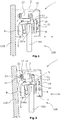
- eine schematische Schnittdarstellung einer erfindungsgemäßen Tragstruktur in einer Stellung, in der die Laufschiene an einer Wand befestigt ist,
- Figuren 2 und 3
- eine schematische Schnittansicht der in
Figur 1 dargestellten erfindungsgemäßen Tragstruktur in einem gegenüber der Vertikalen verkippt befestigten Zustand der Laufschiene, und - Figur 4
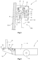
- eine schematische seitliche Ansicht eines Laufwerks.
- In dem in den
Figuren 1-3 dargestellten Ausführungsbeispiel der Erfindung ist ein Koppler 11 an einem Laufwerksrahmen 9 befestigt. - Eine Dämpfereinheit 13 ist in der Laufschiene 3 befestigt. Die Dämpfereinheit 13 weist ein Angreifteil 15 auf, wobei der Koppler 11 rastend mit dem Angreifteil 15 zusammengreifen kann. Die Dämpfereinheit 13 dient zum Abbremsen der Bewegung des Türflügels 101 während einer Bewegung in eine Endstellung. Die Dämpfereinheit 13 ist mit einer Einzugsfunktion versehen, so dass die Bewegung abgedämpft wird und beispielsweise über eine Feder der Türflügel 101 in die Endstellung gezogen wird. Das Angreifteil 15 ist dabei so ausgestaltet, dass der Koppler 11 während des Verfahrens des Türflügels 101 sowohl einer Druckkraft zum Abdämpfen der Bewegung entgegengewirkt werden kann, als auch eine Druckkraft auf den Koppler 11 ausgeübt werden kann, um die Einzugsfunktion zu gewährleisten. Dazu greift das Angreifteil 15 um den Koppler 11. Das Angreifteil 15 kann dabei so ausgestaltet sein, dass der Koppler 11 beim Verfahren des Türflügels 101 aus der Endstellung heraus das Angreifteil 15 zunächst von dem Koppler 11 mitgenommen wird und das Angreifteil 15 diesen dann beim Erreichen einer Ausgangsstellung der Dämpfereinheit 13 freigibt. Beim Verfahren des Türflügels 101 in die Endstellung ist der Koppler 11 zunächst bis zum Erreichen der Ausgangsstellung der Dämpfereinheit 13 frei verfahrbar und wird dann von dem Angreifteil 15 eingefangen.
- Der Koppler 11 ist über ein Verstellsystem 17 an dem Laufwerksrahmen 9 des Laufwerks 7 befestigt. Dazu weist das Verstellsystem 17 eine Schraubenverbindung 19 und eine oder mehrere Abstandsplatten 21 auf. In dem in
Figur 1 dargestellten Ausführungsbeispiel ist eine Abstandsplatte 21 eingesetzt, wohingegen inFigur 2 zwei Abstandsplatten 21 eingesetzt sind. Über das Verstellsystem 17 lässt sich die Position des Kopplers 11 und des Angreifteils 15 zueinander zumindest in horizontaler Richtung einstellen. Die horizontale Richtung ist in denFiguren 1-3 durch einen Doppelpfeil gekennzeichnet. Wie ausFigur 2 hervorgeht, entsteht aufgrund des ungenauen Einbaus des Tragsystems 1, der durch die Schräglage der Wand 110 hervorgerufen wird, ein Verkippen der Laufschiene 3. Aufgrund der Schwerkraft oder durch eine Bodenführung wird jedoch der Türflügel 101 der Schiebetür 100 in eine vertikale Position forciert. Dadurch wird auch die Position des Kopplers 11 zu dem Angreifteil 15 verändert, was dazu führen kann, dass ohne das Verstellsystem ein wirksames Zusammengreifen zwischen Koppler 11 und Angreifteil 15 nicht möglich ist. - Durch das Verstellsystem 17 kann, wie insbesondere aus den
Figuren 2 und3 hervorgeht, die horizontale Position des Kopplers 11 verändert werden, indem das Verstellsystem 17 verstellt wird. Dazu wird die Schraubverbindung 19 gelöst und die Abstandsplatten 21 werden hinzugefügt oder entnommen, bevor die Schraubverbindung 19 wieder festgezogen wird. Durch das Hinzufügen einer Abstandsplatte 21 kann, wie ausFigur 2 hervorgeht, der Koppler 11 in Richtung der Dämpfereinheit 13 verschoben werden. Wie ausFigur 3 hervorgeht, kann durch das Entfernen der Abstandsplatten der Koppler 11 in horizontaler Richtung von der Dämpfereinheit 13 wegbewegt werden, um ein Anstoßen des Koppiers 11 gegen die Dämpfereinheit 13 oder ein Schleifen des Kopplers 11 an einer Dämpfereinheit 13 zu vermeiden.
Wie ausFigur 2 hervorgeht, kann das Verstellsystem 17 auch an der Dämpfereinheit 13 angeordnet sein, wobei das Verstellsystem 17 die Dämpfereinheit 13 mit der Laufschiene 3 verbindet. Der an der Dämpfereinheit 13 angeordnete Teil des Verstellsystems 17 kann zusätzlich oder alternativ zu dem Teil des Verstellsystems 17 an dem Koppler 11 vorgesehen sein.
Das Verstellsystem 17 an der Dämpfereinheit 13 ermöglicht eine Verstellung der Dämpfereinheit 13 und somit des Angreifteils 15, so dass eine Einstellung der Position des Kopplers 11 und des Angreifteils 15 zueinander möglich ist. Die Verstellung der Dämpfereinheit 13 erfolgt in einem spitzen Winkel zu der Horizontalen, so dass eine Verstellung mit einem Anteil in horizontaler Richtung erfolgt. Dadurch ist gewährleistet, dass das Angreifteil 15 zu dem Koppler 11 hin verstellt wird. Der bei der Verstellung entstehende Versatz in vertikaler Richtung ist dabei unerheblich, da der Koppler 11 ausreichend lang ausgestaltet ist, so dass durch den Versatz lediglich die Stelle, an der das Angreifteil 15 an dem Koppler 11 angreift, in vertikaler Richtung verschoben wird.
Das Verstellsystem 17, das an der Dämpfereinheit 13 angeordnet ist, weist mehrere Nutensteine 23 auf, die in eine Nut 25 der Laufschiene 3 eingeführt sind. Die Position der Dämpfereinheit 13 kann verstellt werden, indem Abstandsplatten 21 zwischen der Laufschiene 3 und der Dämpfereinheit 13 angeordnet werden. - Das Verstellsystem 17 kann eine lineare Verstellung des Kopplers oder des Angreifteils bewirken, wie es in den
Figuren 1-3 dargestellt ist, oder eine Verstellung entlang einer Verschwenkbahn, so dass eine zweidimensionale Verstellung erfolgt. - In
Figur 4 ist ein Laufwerk 7 des erfindungsgemäßen Tragsystems 1 in schematischer Seitenansicht gezeigt.
Das Laufwerk 7 besteht aus einem Laufwerkrahmen 9, über den das Laufwerk an einer Oberkante eines Türflügels einer Schiebetür befestigt werden kann. An dem Laufwerkrahmen 9 ist eine Laufrolle 8 befestigt, über die das Laufwerk in eine Laufschiene eingehängt werden kann.
An dem in Laufrichtung in eine Endstellung hinteren Ende 7a ist an dem Laufwerksrahmen 9 ein Koppler 11 befestigt. Die Laufrichtung in die Endstellung ist inFigur 4 durch einen entsprechenden Pfeil dargestellt. Der Koppler 11 ist über ein Verstellsystem 17 mit dem Laufwerksrahmen 9 verbunden. Das Verstellsystem 17 besteht in dem inFigur 4 dargestellten Ausführungsbeispiel aus einer Schraubverbindung 19 und inFigur 4 verdeckt dargestellten Abstandsplatten 21. Durch ein Lösen der Schraubverbindung 19 können die Abstandsplatten 21 zwischen dem Laufwerksrahmen 9 und dem Koppler 11 angeordnet werden, so dass der Koppler 11 in horizontaler Richtung verschoben werden kann. Dadurch kann die Position des Kopplers 11 in Bezug auf ein Angreifteil eines Dämpfers, mit dem der Koppler 11 zusammenwirkt, eingestellt werden. Eine entsprechende Funktion ist auch in Bezug auf dieFiguren 1-3 beschrieben. - Die Verstelleinrichtung 17 kann auch ohne Abstandsplatten ausgebildet sein. Beispielsweise kann die Schraubverbindung 19 aus einem in dem Laufwerksrahmen 9 gelagerten Schraubbolzen bestehen, der in ein Innengewinde in den Koppler 11 eingreift. Durch eine Drehung des Schraubbolzens kann dann eine horizontale Verschiebung des Kopplers 11 vorgenommen werden. Das Verstellsystem 17 kann dabei noch eine Führungsvorrichtung für den Koppler 11 aufweisen, um eine zuverlässige Funktion der Verstellung des Kopplers zu gewährleisten.
- Das erfindungsgemäße Tragsystem hat den Vorteil, dass eine Anpassung bei ungenauem Einbau einer Laufschiene bzw. des erfindungsgemäßen Tragsystems 1 ermöglicht werden kann. Dabei kann die Anpassung der Position des Kopplers 11 zu dem Angreifteil 15 auch nach dem Einhängen des Laufwerks 7 mit dem Türflügel 101 in die Laufschiene 3 erfolgen, so dass ein besonders einfacher Einbau einer Schiebetür ermöglicht wird. Selbstverständlich ist es auch möglich, dass die Position des Kopplers und des Angreifteils zueinander zu einem späteren Zeitpunkt angepasst wird, wenn beispielsweise durch Verschleißerscheinungen die zuverlässige Funktion des Laufwerks 7 mit der Dämpfereinheit 13 nicht mehr gewährleistet ist.
Das Tragsystem 1 besteht aus einer im Wesentlichen L-förmig ausgebildeten Laufschiene 3, die an der Wand 110 befestigt ist. Die Laufschiene 3 weist eine Laufbahn 5 zum Führen eines Laufwerks 7 auf. Das Laufwerk 7 ist an einer oberen Kante 101a eines Türflügels 101 der Schiebetür 100 befestigt, indem das Laufwerk 7 die obere Kante 101a mit einem Laufwerksrahmen 9 umgreift. Das Laufwerk 7 rollt über eine Laufrolle 8 reibungsarm auf der Laufbahn 5 ab.
Claims (7)
- Tragsystem (1) für eine Schiebetür (100),
mit einer Laufschiene (3), mit
mindestens einem Laufwerk (7) mit einem Laufwerksrahmen (9), wobei über das Laufwerk (7) ein Türflügel (101) der Schiebetür (100) in die Laufschiene (3) einhängbar ist, mit einer Dämpfereinheit (13) mit Einzugsfunktion und mit einem Angreifteil (15),
und einem Koppler (11), der
mit dem Angreifteil (15) der Dämpfereinheit (13) rastend zusammengreift, wobei die Dämpfereinheit (13) den Türflügel während einer Bewegung in die Endstellung abbremst und in die Endstellung zieht,
wobei die Dämpfereinheit (13) und/oder der Koppler (11) ein Verstellsystem (17) aufweist, wobei über das Verstellsystem (17) die Position des Kopplers (11) und des Angreifteils (15) zueinander zumindest horizontal einstellbar ist, wobei der Koppler (11) und das Angreifteil (15) in orthogonaler Richtung zur Längsrichtung der Laufschiene (3) aufeinander zu oder voneinander weg bewegbar sind, dadurch gekennzeichnet,
dass die Dämpfereinheit (13) über das Verstellsystem (17) an der Laufschiene (3) befestigt ist, oder/und
dass der Koppler (11) über das Verstellsystem (17) an dem Laufwerksrahmen (9) befestigt ist. - Tragsystem (1) nach Anspruch 1, dadurch gekennzeichnet, dass bei über das Verstellsystem (17) am Laufwerksrahmen befestigtem Koppler (11) der Koppler (11) an dem in Richtung der Endstellung hinteren Ende (7a) des Laufwerks (7) angeordnet ist.
- Tragsystem (1) nach Anspruch 1 oder 2, dadurch gekennzeichnet, dass bei über das Verstellsystem (17) am Laufwerksrahmen befestigtem Koppler (11) das Verstellsystem (17) eine Schraubverbindung (19) zwischen Koppler (11) und Laufwerksrahmen (9) aufweist.
- Tragsystem (1) nach einem der Ansprüche 1 bis 3, dadurch gekennzeichnet, dass bei über das Verstellsystem (17) am Laufwerksrahmen befestigtem Koppler (11)
das Verstellsystem (17) ein oder mehrere Abstandsplatten (21) aufweist, die zwischen dem Koppler (11) und dem Laufwerksrahmen (9) anordenbar sind. - Tragsystem (1) nach Anspruch 1, dadurch gekennzeichnet, dass bei über das Verstellsystem (17) an der Laufschiene befestigter Dämpfereinheit (13) das
Verstellsystem (17) Abstandsplatten (21) aufweist, die zwischen der Dämpfereinheit (13) und der Laufschiene (3) anordenbar sind. - Tragsystem (1) nach einem der Ansprüche 1 bis 5, dadurch gekennzeichnet, dass das Verstellsystem (17) ein lineares Verstellsystem oder ein zweidimensionales Verstellsystem ist.
- Verfahren zum Einbau einer Schiebetür (100) mit einem Tragsystem (1) nach einem der Ansprüche 1 bis 6, mit folgenden Schritten:- Befestigen einer Laufschiene (3) an einer Wand (110) oder Decke,- Befestigen eines einen Koppler (11) aufweisenden Laufwerks (7) an einer Kante (101a) eines Türflügels (101) der Schiebetür (100),- Befestigen einer einen Angreifteil (15) aufweisenden Dämpfereinheit (13) an der Laufschiene (3),- Einhängen des Laufwerks (7) in die Laufschiene (3),- Verstellen der Position des Kopplers (11) und des Angreifteils (15) zueinander zumindest horizontal in orthogonaler Richtung zu der Längsrichtung der Laufschiene (3) zum Ausgleich von Fehlpositionen des Kopplers (11) und des Angreifteils (15) aufgrund von Einbauungenauigkeiten.
Applications Claiming Priority (1)
| Application Number | Priority Date | Filing Date | Title |
|---|---|---|---|
| DE102011107961.4A DE102011107961B4 (de) | 2011-07-20 | 2011-07-20 | Tragsystem für eine Schiebetür |
Publications (3)
| Publication Number | Publication Date |
|---|---|
| EP2549043A2 EP2549043A2 (de) | 2013-01-23 |
| EP2549043A3 EP2549043A3 (de) | 2013-08-14 |
| EP2549043B1 true EP2549043B1 (de) | 2017-03-15 |
Family
ID=46516580
Family Applications (1)
| Application Number | Title | Priority Date | Filing Date |
|---|---|---|---|
| EP12176411.2A Active EP2549043B1 (de) | 2011-07-20 | 2012-07-13 | Tragsystem für eine Schiebetür |
Country Status (4)
| Country | Link |
|---|---|
| EP (1) | EP2549043B1 (de) |
| DE (2) | DE202011111038U1 (de) |
| ES (1) | ES2628366T3 (de) |
| PL (1) | PL2549043T3 (de) |
Cited By (1)
| Publication number | Priority date | Publication date | Assignee | Title |
|---|---|---|---|---|
| DE102018202813C5 (de) * | 2018-02-23 | 2024-11-21 | Geze Gmbh | Mechanischer Auslöser |
Citations (2)
| Publication number | Priority date | Publication date | Assignee | Title |
|---|---|---|---|---|
| DE102009005441A1 (de) * | 2008-06-14 | 2009-12-17 | Gebr. Willach Gmbh | Schiebetür |
| DE202010003932U1 (de) * | 2009-03-27 | 2010-07-29 | Koblenz S.P.A., Coriano | Versenkbare Schiebetür |
Family Cites Families (4)
| Publication number | Priority date | Publication date | Assignee | Title |
|---|---|---|---|---|
| DE9011081U1 (de) * | 1990-07-27 | 1990-10-04 | Geze GmbH & Co, 7250 Leonberg | Schiebetürbeschlag mit einer Feststellpuffereinrichtung |
| JP3930459B2 (ja) * | 2003-06-30 | 2007-06-13 | 株式会社シモダイラ | 引戸の戸閉装置 |
| JP4751607B2 (ja) * | 2004-12-20 | 2011-08-17 | 株式会社ニフコ | 自走往動させる機構、引き戸機構、および、引き出し機構 |
| WO2008028945A2 (en) * | 2006-09-06 | 2008-03-13 | Liexco S.A. | Modular rail system for suspending sliding doors and sliding door system with user accessible braking / stopping element |
-
2011
- 2011-07-20 DE DE202011111038.2U patent/DE202011111038U1/de not_active Expired - Lifetime
- 2011-07-20 DE DE102011107961.4A patent/DE102011107961B4/de not_active Expired - Fee Related
-
2012
- 2012-07-13 PL PL12176411T patent/PL2549043T3/pl unknown
- 2012-07-13 EP EP12176411.2A patent/EP2549043B1/de active Active
- 2012-07-13 ES ES12176411.2T patent/ES2628366T3/es active Active
Patent Citations (2)
| Publication number | Priority date | Publication date | Assignee | Title |
|---|---|---|---|---|
| DE102009005441A1 (de) * | 2008-06-14 | 2009-12-17 | Gebr. Willach Gmbh | Schiebetür |
| DE202010003932U1 (de) * | 2009-03-27 | 2010-07-29 | Koblenz S.P.A., Coriano | Versenkbare Schiebetür |
Cited By (1)
| Publication number | Priority date | Publication date | Assignee | Title |
|---|---|---|---|---|
| DE102018202813C5 (de) * | 2018-02-23 | 2024-11-21 | Geze Gmbh | Mechanischer Auslöser |
Also Published As
| Publication number | Publication date |
|---|---|
| ES2628366T3 (es) | 2017-08-02 |
| DE102011107961B4 (de) | 2021-05-20 |
| PL2549043T3 (pl) | 2017-09-29 |
| EP2549043A3 (de) | 2013-08-14 |
| DE102011107961A1 (de) | 2013-01-24 |
| DE202011111038U1 (de) | 2018-08-21 |
| EP2549043A2 (de) | 2013-01-23 |
Similar Documents
| Publication | Publication Date | Title |
|---|---|---|
| DE102009005441B4 (de) | Schiebetür | |
| EP2376734B1 (de) | Schiebetür | |
| EP2217782A1 (de) | Vorrichtung zum einziehen und dämpfen einer in einer profilschiene zum führen von laufwerken getragenen schiebetür in die endlage | |
| EP2333218A1 (de) | Einrichtung zum Dämpfen der Relativbewegung bewegter Vorrichtungsteile, insbesondere von Schiebetüren | |
| EP2925947B1 (de) | Rolltor mit einem torblatt in gestalt eines flexiblen behangs | |
| DE102012202986A1 (de) | Beschlag für eine Schiebetür oder ein Schiebefenster | |
| EP2678507B1 (de) | Glasschiebetür | |
| DE102013102939B4 (de) | Beschleunigungs- und/oder Bremsvorrichtung | |
| EP3211164B1 (de) | Schiebetürsystem | |
| WO2010066391A1 (de) | Schiebetür | |
| EP2365168B1 (de) | Beschlag zum Bremsen der Relativbewegung bewegter Vorrichtungsteile, insbesondere von Schiebetüren | |
| EP3045643B1 (de) | Torblatt | |
| DE102014118087A1 (de) | Führungsvorrichtung für linear bewegbare Möbelbauteile | |
| DE102011107961B4 (de) | Tragsystem für eine Schiebetür | |
| EP2843169A1 (de) | Tragsystem für eine Schiebetür, sowie Schiebetür | |
| CH702408B1 (de) | Hochwasserschutzvorrichtung. | |
| DE102007007564A1 (de) | Hochwasserschutzvorrichtung | |
| EP3695081B1 (de) | Tor mit einem unteren torglied mit klapprollenhalter | |
| EP3156574A1 (de) | Anordnung mit einer schiebetür und mit einem ortsfesten teil, an welchem die schiebetür verschiebbar geführt ist | |
| EP2045425B1 (de) | Einblatt-Überkopftor sowie Vorspanneinrichtung hierfür | |
| DE102010030709B4 (de) | Schiebetüranlage | |
| AT501777A2 (de) | Schubladenführung | |
| DE202018104314U1 (de) | Schutzvorrichtung für Roll- und Sektionaltore | |
| DE102018202813C5 (de) | Mechanischer Auslöser | |
| EP2746667A1 (de) | Mechanismus zum Hochschieben und Schliessen von Kamintüren |
Legal Events
| Date | Code | Title | Description |
|---|---|---|---|
| PUAI | Public reference made under article 153(3) epc to a published international application that has entered the european phase |
Free format text: ORIGINAL CODE: 0009012 |
|
| AK | Designated contracting states |
Kind code of ref document: A2 Designated state(s): AL AT BE BG CH CY CZ DE DK EE ES FI FR GB GR HR HU IE IS IT LI LT LU LV MC MK MT NL NO PL PT RO RS SE SI SK SM TR |
|
| AX | Request for extension of the european patent |
Extension state: BA ME |
|
| PUAL | Search report despatched |
Free format text: ORIGINAL CODE: 0009013 |
|
| AK | Designated contracting states |
Kind code of ref document: A3 Designated state(s): AL AT BE BG CH CY CZ DE DK EE ES FI FR GB GR HR HU IE IS IT LI LT LU LV MC MK MT NL NO PL PT RO RS SE SI SK SM TR |
|
| AX | Request for extension of the european patent |
Extension state: BA ME |
|
| RIC1 | Information provided on ipc code assigned before grant |
Ipc: E05D 15/06 20060101ALI20130709BHEP Ipc: E05F 5/00 20060101AFI20130709BHEP |
|
| 17P | Request for examination filed |
Effective date: 20140211 |
|
| RBV | Designated contracting states (corrected) |
Designated state(s): AL AT BE BG CH CY CZ DE DK EE ES FI FR GB GR HR HU IE IS IT LI LT LU LV MC MK MT NL NO PL PT RO RS SE SI SK SM TR |
|
| 17Q | First examination report despatched |
Effective date: 20150415 |
|
| GRAP | Despatch of communication of intention to grant a patent |
Free format text: ORIGINAL CODE: EPIDOSNIGR1 |
|
| INTG | Intention to grant announced |
Effective date: 20160823 |
|
| GRAS | Grant fee paid |
Free format text: ORIGINAL CODE: EPIDOSNIGR3 |
|
| STAA | Information on the status of an ep patent application or granted ep patent |
Free format text: STATUS: GRANT OF PATENT IS INTENDED |
|
| GRAJ | Information related to disapproval of communication of intention to grant by the applicant or resumption of examination proceedings by the epo deleted |
Free format text: ORIGINAL CODE: EPIDOSDIGR1 |
|
| GRAL | Information related to payment of fee for publishing/printing deleted |
Free format text: ORIGINAL CODE: EPIDOSDIGR3 |
|
| STAA | Information on the status of an ep patent application or granted ep patent |
Free format text: STATUS: EXAMINATION IS IN PROGRESS |
|
| GRAP | Despatch of communication of intention to grant a patent |
Free format text: ORIGINAL CODE: EPIDOSNIGR1 |
|
| STAA | Information on the status of an ep patent application or granted ep patent |
Free format text: STATUS: GRANT OF PATENT IS INTENDED |
|
| GRAA | (expected) grant |
Free format text: ORIGINAL CODE: 0009210 |
|
| STAA | Information on the status of an ep patent application or granted ep patent |
Free format text: STATUS: THE PATENT HAS BEEN GRANTED |
|
| INTC | Intention to grant announced (deleted) | ||
| RIN1 | Information on inventor provided before grant (corrected) |
Inventor name: STOMMEL, WILFRIED Inventor name: WILLACH, JENS, DR. |
|
| INTG | Intention to grant announced |
Effective date: 20170125 |
|
| AK | Designated contracting states |
Kind code of ref document: B1 Designated state(s): AL AT BE BG CH CY CZ DE DK EE ES FI FR GB GR HR HU IE IS IT LI LT LU LV MC MK MT NL NO PL PT RO RS SE SI SK SM TR |
|
| REG | Reference to a national code |
Ref country code: GB Ref legal event code: FG4D Free format text: NOT ENGLISH Ref country code: CH Ref legal event code: EP |
|
| REG | Reference to a national code |
Ref country code: IE Ref legal event code: FG4D Free format text: LANGUAGE OF EP DOCUMENT: GERMAN |
|
| REG | Reference to a national code |
Ref country code: AT Ref legal event code: REF Ref document number: 875769 Country of ref document: AT Kind code of ref document: T Effective date: 20170415 |
|
| REG | Reference to a national code |
Ref country code: DE Ref legal event code: R096 Ref document number: 502012009766 Country of ref document: DE |
|
| REG | Reference to a national code |
Ref country code: NL Ref legal event code: FP |
|
| REG | Reference to a national code |
Ref country code: FR Ref legal event code: PLFP Year of fee payment: 6 |
|
| REG | Reference to a national code |
Ref country code: LT Ref legal event code: MG4D |
|
| PG25 | Lapsed in a contracting state [announced via postgrant information from national office to epo] |
Ref country code: NO Free format text: LAPSE BECAUSE OF FAILURE TO SUBMIT A TRANSLATION OF THE DESCRIPTION OR TO PAY THE FEE WITHIN THE PRESCRIBED TIME-LIMIT Effective date: 20170615 Ref country code: HR Free format text: LAPSE BECAUSE OF FAILURE TO SUBMIT A TRANSLATION OF THE DESCRIPTION OR TO PAY THE FEE WITHIN THE PRESCRIBED TIME-LIMIT Effective date: 20170315 Ref country code: FI Free format text: LAPSE BECAUSE OF FAILURE TO SUBMIT A TRANSLATION OF THE DESCRIPTION OR TO PAY THE FEE WITHIN THE PRESCRIBED TIME-LIMIT Effective date: 20170315 Ref country code: GR Free format text: LAPSE BECAUSE OF FAILURE TO SUBMIT A TRANSLATION OF THE DESCRIPTION OR TO PAY THE FEE WITHIN THE PRESCRIBED TIME-LIMIT Effective date: 20170616 Ref country code: LT Free format text: LAPSE BECAUSE OF FAILURE TO SUBMIT A TRANSLATION OF THE DESCRIPTION OR TO PAY THE FEE WITHIN THE PRESCRIBED TIME-LIMIT Effective date: 20170315 |
|
| REG | Reference to a national code |
Ref country code: ES Ref legal event code: FG2A Ref document number: 2628366 Country of ref document: ES Kind code of ref document: T3 Effective date: 20170802 |
|
| PG25 | Lapsed in a contracting state [announced via postgrant information from national office to epo] |
Ref country code: SE Free format text: LAPSE BECAUSE OF FAILURE TO SUBMIT A TRANSLATION OF THE DESCRIPTION OR TO PAY THE FEE WITHIN THE PRESCRIBED TIME-LIMIT Effective date: 20170315 Ref country code: LV Free format text: LAPSE BECAUSE OF FAILURE TO SUBMIT A TRANSLATION OF THE DESCRIPTION OR TO PAY THE FEE WITHIN THE PRESCRIBED TIME-LIMIT Effective date: 20170315 Ref country code: BG Free format text: LAPSE BECAUSE OF FAILURE TO SUBMIT A TRANSLATION OF THE DESCRIPTION OR TO PAY THE FEE WITHIN THE PRESCRIBED TIME-LIMIT Effective date: 20170615 Ref country code: RS Free format text: LAPSE BECAUSE OF FAILURE TO SUBMIT A TRANSLATION OF THE DESCRIPTION OR TO PAY THE FEE WITHIN THE PRESCRIBED TIME-LIMIT Effective date: 20170315 |
|
| PG25 | Lapsed in a contracting state [announced via postgrant information from national office to epo] |
Ref country code: RO Free format text: LAPSE BECAUSE OF FAILURE TO SUBMIT A TRANSLATION OF THE DESCRIPTION OR TO PAY THE FEE WITHIN THE PRESCRIBED TIME-LIMIT Effective date: 20170315 Ref country code: SK Free format text: LAPSE BECAUSE OF FAILURE TO SUBMIT A TRANSLATION OF THE DESCRIPTION OR TO PAY THE FEE WITHIN THE PRESCRIBED TIME-LIMIT Effective date: 20170315 Ref country code: CZ Free format text: LAPSE BECAUSE OF FAILURE TO SUBMIT A TRANSLATION OF THE DESCRIPTION OR TO PAY THE FEE WITHIN THE PRESCRIBED TIME-LIMIT Effective date: 20170315 Ref country code: EE Free format text: LAPSE BECAUSE OF FAILURE TO SUBMIT A TRANSLATION OF THE DESCRIPTION OR TO PAY THE FEE WITHIN THE PRESCRIBED TIME-LIMIT Effective date: 20170315 |
|
| PG25 | Lapsed in a contracting state [announced via postgrant information from national office to epo] |
Ref country code: PT Free format text: LAPSE BECAUSE OF FAILURE TO SUBMIT A TRANSLATION OF THE DESCRIPTION OR TO PAY THE FEE WITHIN THE PRESCRIBED TIME-LIMIT Effective date: 20170717 Ref country code: SM Free format text: LAPSE BECAUSE OF FAILURE TO SUBMIT A TRANSLATION OF THE DESCRIPTION OR TO PAY THE FEE WITHIN THE PRESCRIBED TIME-LIMIT Effective date: 20170315 Ref country code: IS Free format text: LAPSE BECAUSE OF FAILURE TO SUBMIT A TRANSLATION OF THE DESCRIPTION OR TO PAY THE FEE WITHIN THE PRESCRIBED TIME-LIMIT Effective date: 20170715 |
|
| REG | Reference to a national code |
Ref country code: DE Ref legal event code: R097 Ref document number: 502012009766 Country of ref document: DE |
|
| PLBE | No opposition filed within time limit |
Free format text: ORIGINAL CODE: 0009261 |
|
| STAA | Information on the status of an ep patent application or granted ep patent |
Free format text: STATUS: NO OPPOSITION FILED WITHIN TIME LIMIT |
|
| PG25 | Lapsed in a contracting state [announced via postgrant information from national office to epo] |
Ref country code: DK Free format text: LAPSE BECAUSE OF FAILURE TO SUBMIT A TRANSLATION OF THE DESCRIPTION OR TO PAY THE FEE WITHIN THE PRESCRIBED TIME-LIMIT Effective date: 20170315 |
|
| 26N | No opposition filed |
Effective date: 20171218 |
|
| PG25 | Lapsed in a contracting state [announced via postgrant information from national office to epo] |
Ref country code: SI Free format text: LAPSE BECAUSE OF FAILURE TO SUBMIT A TRANSLATION OF THE DESCRIPTION OR TO PAY THE FEE WITHIN THE PRESCRIBED TIME-LIMIT Effective date: 20170315 |
|
| REG | Reference to a national code |
Ref country code: CH Ref legal event code: PL |
|
| REG | Reference to a national code |
Ref country code: IE Ref legal event code: MM4A |
|
| PG25 | Lapsed in a contracting state [announced via postgrant information from national office to epo] |
Ref country code: CH Free format text: LAPSE BECAUSE OF NON-PAYMENT OF DUE FEES Effective date: 20170731 Ref country code: LI Free format text: LAPSE BECAUSE OF NON-PAYMENT OF DUE FEES Effective date: 20170731 Ref country code: IE Free format text: LAPSE BECAUSE OF NON-PAYMENT OF DUE FEES Effective date: 20170713 |
|
| REG | Reference to a national code |
Ref country code: BE Ref legal event code: MM Effective date: 20170731 |
|
| PG25 | Lapsed in a contracting state [announced via postgrant information from national office to epo] |
Ref country code: LU Free format text: LAPSE BECAUSE OF NON-PAYMENT OF DUE FEES Effective date: 20170713 |
|
| REG | Reference to a national code |
Ref country code: FR Ref legal event code: PLFP Year of fee payment: 7 |
|
| PG25 | Lapsed in a contracting state [announced via postgrant information from national office to epo] |
Ref country code: BE Free format text: LAPSE BECAUSE OF NON-PAYMENT OF DUE FEES Effective date: 20170731 |
|
| PG25 | Lapsed in a contracting state [announced via postgrant information from national office to epo] |
Ref country code: MT Free format text: LAPSE BECAUSE OF FAILURE TO SUBMIT A TRANSLATION OF THE DESCRIPTION OR TO PAY THE FEE WITHIN THE PRESCRIBED TIME-LIMIT Effective date: 20170315 |
|
| PG25 | Lapsed in a contracting state [announced via postgrant information from national office to epo] |
Ref country code: HU Free format text: LAPSE BECAUSE OF FAILURE TO SUBMIT A TRANSLATION OF THE DESCRIPTION OR TO PAY THE FEE WITHIN THE PRESCRIBED TIME-LIMIT; INVALID AB INITIO Effective date: 20120713 Ref country code: MC Free format text: LAPSE BECAUSE OF FAILURE TO SUBMIT A TRANSLATION OF THE DESCRIPTION OR TO PAY THE FEE WITHIN THE PRESCRIBED TIME-LIMIT Effective date: 20170315 |
|
| PG25 | Lapsed in a contracting state [announced via postgrant information from national office to epo] |
Ref country code: CY Free format text: LAPSE BECAUSE OF NON-PAYMENT OF DUE FEES Effective date: 20170315 |
|
| PG25 | Lapsed in a contracting state [announced via postgrant information from national office to epo] |
Ref country code: MK Free format text: LAPSE BECAUSE OF FAILURE TO SUBMIT A TRANSLATION OF THE DESCRIPTION OR TO PAY THE FEE WITHIN THE PRESCRIBED TIME-LIMIT Effective date: 20170315 |
|
| PG25 | Lapsed in a contracting state [announced via postgrant information from national office to epo] |
Ref country code: TR Free format text: LAPSE BECAUSE OF FAILURE TO SUBMIT A TRANSLATION OF THE DESCRIPTION OR TO PAY THE FEE WITHIN THE PRESCRIBED TIME-LIMIT Effective date: 20170315 |
|
| PG25 | Lapsed in a contracting state [announced via postgrant information from national office to epo] |
Ref country code: AL Free format text: LAPSE BECAUSE OF FAILURE TO SUBMIT A TRANSLATION OF THE DESCRIPTION OR TO PAY THE FEE WITHIN THE PRESCRIBED TIME-LIMIT Effective date: 20170315 |
|
| P01 | Opt-out of the competence of the unified patent court (upc) registered |
Effective date: 20230427 |
|
| PGFP | Annual fee paid to national office [announced via postgrant information from national office to epo] |
Ref country code: NL Payment date: 20240722 Year of fee payment: 13 |
|
| PGFP | Annual fee paid to national office [announced via postgrant information from national office to epo] |
Ref country code: GB Payment date: 20240723 Year of fee payment: 13 |
|
| PGFP | Annual fee paid to national office [announced via postgrant information from national office to epo] |
Ref country code: FR Payment date: 20240724 Year of fee payment: 13 |
|
| PGFP | Annual fee paid to national office [announced via postgrant information from national office to epo] |
Ref country code: ES Payment date: 20240816 Year of fee payment: 13 |
|
| PGFP | Annual fee paid to national office [announced via postgrant information from national office to epo] |
Ref country code: PL Payment date: 20240704 Year of fee payment: 13 |
|
| PGFP | Annual fee paid to national office [announced via postgrant information from national office to epo] |
Ref country code: IT Payment date: 20240731 Year of fee payment: 13 |
|
| PGFP | Annual fee paid to national office [announced via postgrant information from national office to epo] |
Ref country code: DE Payment date: 20250717 Year of fee payment: 14 |
|
| PGFP | Annual fee paid to national office [announced via postgrant information from national office to epo] |
Ref country code: AT Payment date: 20250721 Year of fee payment: 14 |
|
| REG | Reference to a national code |
Ref country code: NL Ref legal event code: MM Effective date: 20250801 |
|
| GBPC | Gb: european patent ceased through non-payment of renewal fee |
Effective date: 20250713 |
|
| PG25 | Lapsed in a contracting state [announced via postgrant information from national office to epo] |
Ref country code: GB Free format text: LAPSE BECAUSE OF NON-PAYMENT OF DUE FEES Effective date: 20250713 |
|
| PG25 | Lapsed in a contracting state [announced via postgrant information from national office to epo] |
Ref country code: NL Free format text: LAPSE BECAUSE OF NON-PAYMENT OF DUE FEES Effective date: 20250801 |
|
| PG25 | Lapsed in a contracting state [announced via postgrant information from national office to epo] |
Ref country code: FR Free format text: LAPSE BECAUSE OF NON-PAYMENT OF DUE FEES Effective date: 20250731 |