EP2549010A1 - Method for cutting carbon fiber base - Google Patents
Method for cutting carbon fiber base Download PDFInfo
- Publication number
- EP2549010A1 EP2549010A1 EP10847998A EP10847998A EP2549010A1 EP 2549010 A1 EP2549010 A1 EP 2549010A1 EP 10847998 A EP10847998 A EP 10847998A EP 10847998 A EP10847998 A EP 10847998A EP 2549010 A1 EP2549010 A1 EP 2549010A1
- Authority
- EP
- European Patent Office
- Prior art keywords
- cutting
- carbon fiber
- laser
- substrate
- fiber substrate
- Prior art date
- Legal status (The legal status is an assumption and is not a legal conclusion. Google has not performed a legal analysis and makes no representation as to the accuracy of the status listed.)
- Withdrawn
Links
Images



Classifications
-
- D—TEXTILES; PAPER
- D06—TREATMENT OF TEXTILES OR THE LIKE; LAUNDERING; FLEXIBLE MATERIALS NOT OTHERWISE PROVIDED FOR
- D06H—MARKING, INSPECTING, SEAMING OR SEVERING TEXTILE MATERIALS
- D06H7/00—Apparatus or processes for cutting, or otherwise severing, specially adapted for the cutting, or otherwise severing, of textile materials
- D06H7/22—Severing by heat or by chemical agents
-
- B—PERFORMING OPERATIONS; TRANSPORTING
- B23—MACHINE TOOLS; METAL-WORKING NOT OTHERWISE PROVIDED FOR
- B23K—SOLDERING OR UNSOLDERING; WELDING; CLADDING OR PLATING BY SOLDERING OR WELDING; CUTTING BY APPLYING HEAT LOCALLY, e.g. FLAME CUTTING; WORKING BY LASER BEAM
- B23K26/00—Working by laser beam, e.g. welding, cutting or boring
- B23K26/14—Working by laser beam, e.g. welding, cutting or boring using a fluid stream, e.g. a jet of gas, in conjunction with the laser beam; Nozzles therefor
-
- B—PERFORMING OPERATIONS; TRANSPORTING
- B23—MACHINE TOOLS; METAL-WORKING NOT OTHERWISE PROVIDED FOR
- B23K—SOLDERING OR UNSOLDERING; WELDING; CLADDING OR PLATING BY SOLDERING OR WELDING; CUTTING BY APPLYING HEAT LOCALLY, e.g. FLAME CUTTING; WORKING BY LASER BEAM
- B23K26/00—Working by laser beam, e.g. welding, cutting or boring
- B23K26/16—Removal of by-products, e.g. particles or vapours produced during treatment of a workpiece
-
- B—PERFORMING OPERATIONS; TRANSPORTING
- B23—MACHINE TOOLS; METAL-WORKING NOT OTHERWISE PROVIDED FOR
- B23K—SOLDERING OR UNSOLDERING; WELDING; CLADDING OR PLATING BY SOLDERING OR WELDING; CUTTING BY APPLYING HEAT LOCALLY, e.g. FLAME CUTTING; WORKING BY LASER BEAM
- B23K26/00—Working by laser beam, e.g. welding, cutting or boring
- B23K26/36—Removing material
- B23K26/38—Removing material by boring or cutting
-
- B—PERFORMING OPERATIONS; TRANSPORTING
- B23—MACHINE TOOLS; METAL-WORKING NOT OTHERWISE PROVIDED FOR
- B23K—SOLDERING OR UNSOLDERING; WELDING; CLADDING OR PLATING BY SOLDERING OR WELDING; CUTTING BY APPLYING HEAT LOCALLY, e.g. FLAME CUTTING; WORKING BY LASER BEAM
- B23K26/00—Working by laser beam, e.g. welding, cutting or boring
- B23K26/36—Removing material
- B23K26/40—Removing material taking account of the properties of the material involved
-
- B—PERFORMING OPERATIONS; TRANSPORTING
- B23—MACHINE TOOLS; METAL-WORKING NOT OTHERWISE PROVIDED FOR
- B23K—SOLDERING OR UNSOLDERING; WELDING; CLADDING OR PLATING BY SOLDERING OR WELDING; CUTTING BY APPLYING HEAT LOCALLY, e.g. FLAME CUTTING; WORKING BY LASER BEAM
- B23K26/00—Working by laser beam, e.g. welding, cutting or boring
- B23K26/70—Auxiliary operations or equipment
- B23K26/702—Auxiliary equipment
- B23K26/703—Cooling arrangements
-
- D—TEXTILES; PAPER
- D01—NATURAL OR MAN-MADE THREADS OR FIBRES; SPINNING
- D01F—CHEMICAL FEATURES IN THE MANUFACTURE OF ARTIFICIAL FILAMENTS, THREADS, FIBRES, BRISTLES OR RIBBONS; APPARATUS SPECIALLY ADAPTED FOR THE MANUFACTURE OF CARBON FILAMENTS
- D01F9/00—Artificial filaments or the like of other substances; Manufacture thereof; Apparatus specially adapted for the manufacture of carbon filaments
- D01F9/08—Artificial filaments or the like of other substances; Manufacture thereof; Apparatus specially adapted for the manufacture of carbon filaments of inorganic material
- D01F9/12—Carbon filaments; Apparatus specially adapted for the manufacture thereof
-
- B—PERFORMING OPERATIONS; TRANSPORTING
- B23—MACHINE TOOLS; METAL-WORKING NOT OTHERWISE PROVIDED FOR
- B23K—SOLDERING OR UNSOLDERING; WELDING; CLADDING OR PLATING BY SOLDERING OR WELDING; CUTTING BY APPLYING HEAT LOCALLY, e.g. FLAME CUTTING; WORKING BY LASER BEAM
- B23K2103/00—Materials to be soldered, welded or cut
- B23K2103/16—Composite materials
-
- B—PERFORMING OPERATIONS; TRANSPORTING
- B23—MACHINE TOOLS; METAL-WORKING NOT OTHERWISE PROVIDED FOR
- B23K—SOLDERING OR UNSOLDERING; WELDING; CLADDING OR PLATING BY SOLDERING OR WELDING; CUTTING BY APPLYING HEAT LOCALLY, e.g. FLAME CUTTING; WORKING BY LASER BEAM
- B23K2103/00—Materials to be soldered, welded or cut
- B23K2103/16—Composite materials
- B23K2103/166—Multilayered materials
- B23K2103/172—Multilayered materials wherein at least one of the layers is non-metallic
-
- B—PERFORMING OPERATIONS; TRANSPORTING
- B23—MACHINE TOOLS; METAL-WORKING NOT OTHERWISE PROVIDED FOR
- B23K—SOLDERING OR UNSOLDERING; WELDING; CLADDING OR PLATING BY SOLDERING OR WELDING; CUTTING BY APPLYING HEAT LOCALLY, e.g. FLAME CUTTING; WORKING BY LASER BEAM
- B23K2103/00—Materials to be soldered, welded or cut
- B23K2103/30—Organic materials
- B23K2103/38—Fabrics; Fibrous materials
-
- B—PERFORMING OPERATIONS; TRANSPORTING
- B23—MACHINE TOOLS; METAL-WORKING NOT OTHERWISE PROVIDED FOR
- B23K—SOLDERING OR UNSOLDERING; WELDING; CLADDING OR PLATING BY SOLDERING OR WELDING; CUTTING BY APPLYING HEAT LOCALLY, e.g. FLAME CUTTING; WORKING BY LASER BEAM
- B23K2103/00—Materials to be soldered, welded or cut
- B23K2103/50—Inorganic materials other than metals or composite materials
Definitions
- the present invention relates to a method for cutting a carbon fiber substrate formed from a fabric material comprising carbon fibers, and specifically, to a method for cutting a carbon fiber substrate suitable in use for cutting a substrate, used for making a fiber reinforced plastic (hereinafter, also referred to as "FRP"), precisely at a predetermined shape.
- FRP fiber reinforced plastic
- CFRP fiber reinforced plastic used with carbon fibers
- RTM process is paid attention to from a viewpoint of being able to obtain a CFRP having a complicated shape, for example, by preparing a carbon fiber substrate formed from a fabric material comprising carbon fibers or a laminate stacked with a plurality of the fabric materials, forming a preform with a predetermined shape in advance, and impregnating a matrix resin injected into a mold into the preform and curing the resin.
- a mismatch may occur between it and a cavity shape of the mold.
- the preform is larger than the mold, it is to be performed to conduct an additional cutting processing operation for adjusting the shape to a size fitting to the mold, or to perform molding by containing the preform larger than the mold in the mold as it is.
- carbon fibers are contained up to a flash portion of CFRP after molding, and there occurs an inconvenience that the flash removing operation becomes troublesome.
- the preform is smaller, because a portion of only resin (resin rich portion) is formed in a gap between the preform and the mold, an operation for charging carbon fibers separately becomes necessary before injection of matrix resin.
- an end portion of the preform may be frayed, for example, when the preform is transferred to the mold, and therefore, it is difficult to completely suppress the mismatch.
- the sheet-like molded material described in these documents is used suitably for a carbon fiber electrode, and it is not used by additionally impregnating a matrix resin into the sheet-like molded material. Further, since the whole of the short carbon fibers themselves are carbonized because of the calcination at a high temperature of about 200°C or higher, the elastic modulus, the strength, etc. of the short carbon fibers themselves cannot be exhibited.
- the thermal conductivity of carbon fiber itself is higher than that of a general inorganic substance, depending upon the formation of a substrate formed from a fabric material, because there is a case where the thermal conductivity of the substrate in a cutting processing direction, that is, a thickness direction (especially, a thickness direction of a substrate comprising a laminate) becomes extremely low as compared with that of a metal, heat supply through the substrate itself in the thickness direction is hardly achieved, and it may become difficult to reach the cutting temperature of the substrate. If the cutting temperature by a laser is not sufficiently elevated, namely, if it is not elevated up to the sublimation cutting temperature of carbon fibers, a cutting defective place may occur.
- the laser cutting there is a focal distance capable of processing (a focal distance for convergence), and in case where the substrate is one easy to be deformed, there is a fear that the portion to be cut may shift from the range of the focal distance capable of processing and it shifts, a cutting defective place also may occur.
- an object of the present invention is to provide a method for cutting a carbon fiber substrate capable of performing a laser cutting, that can expect an excellent cutting performance and an excellent cutting end surface form as aforementioned for cutting of a carbon fiber substrate, stably at a target desired condition.
- a method for cutting a carbon fiber substrate according to the present invention is characterized in that, when a carbon fiber substrate configured from a fabric material comprising at least carbon fibers is cut with a laser, the substrate is cut at initial conditions which have been set so that the state of the substrate that is being cut with the laser can be suppressed with or prevented from deviating from a target state.
- the carbon fiber substrate configured from a fabric material comprising at least carbon fibers in the present invention includes a carbon fiber substrate configured from substantially any fabric material comprising carbon fibers, and includes both of the fabric material as a single material and a laminate.
- a unidirectional woven fabric substrate arranging carbon fibers in one direction a multiaxial stitched substrate, and formation such as a non-woven fabric, a plain weave, a twill weave, knitting or a braid, are included, and further, a hybrid configuration with glass fibers or organic fibers may be employed.
- a substrate having a laminate configuration except a fabric material comprising carbon fibers, a fabric material comprising glass fibers, aramide fibers, PBO (polyparaphenylene benzobisoxazol) fibers, boron fibers, alumina fibers, etc. may be contained. Then, a preform wherein such a substrate is formed in advance in a predetermined shape (including both two and three dimensional shapes) is also included as a carbon fiber substrate according to the present invention.
- a substrate configured from the above-described carbon fiber containing fabric material comprising carbon fibers of continuous fibers is raised, and more preferably, a carbon fiber containing fabric material comprising only carbon fibers is raised.
- the present invention mainly targets a so-called dry carbon fiber substrate into which a resin (matrix resin) is not impregnated
- a substrate into which a resin is impregnated for example, a prepreg into which a resin is impregnated at a condition of so-called B-stage before being cured, is also included in the carbon fiber substrate according to the present invention.
- specified initial conditions capable of suppressing with or preventing from deviating from a target state as the state of the substrate at the time of being cut with the laser are set, and under the conditions the substrate is cut.
- This suppressing with or preventing from deviating from a target state means suppressing or preventing undesired dissipation of heat due to the laser for cutting as aforementioned, preventing shifting from the range of the laser focal distance capable of processing a portion of the substrate to be cut, further, suppressing or preventing clogging of a head for irradiating the laser, etc.
- a method can be employed wherein, when the carbon fiber substrate is cut with the laser at a condition being placed on a receiving jig, the substrate is partially received by the receiving jig.
- the sublimation cutting temperature of carbon fibers is about 3,800°C to be higher than that of a metal, and because a difference between an atmosphere temperature and the cutting temperature is great, thermal energy is liable to be dissipated.
- thermal conductivity in a cutting processing direction that is, a thickness direction of the substrate
- heat supply through the substrate itself in the thickness direction is hardly achieved, and there is a feature that the temperature at a portion to be cut in the thickness direction hardly reaches the cutting temperature. Therefore, in cutting of such a substrate comprising carbon fibers, it is necessary to greatly suppress the dissipation of thermal energy, and a jig structure becomes important which can set parameters relating to dissipation of thermal energy (thermal conductivity, contact area, temperature difference with a contact object, time for heating, etc. are in proportion to the amount of dissipation, and distance with a contact object is in inverse proportion thereto.) at adequate ranges.
- the thermal capacity of the jig brought into contact with the substrate to be cut is set as small as possible, the jig is elevated in temperature in a short time, and the dissipation of thermal energy may be prevented.
- a cutting position of the substrate is set at a position where the substrate is not brought into contact with the above-described receiving jig.
- the distance between the receiving jig and the cutting point great. Namely, it is better not to receive the back surface of the cutting line.
- the distance with the cutting point is too great, because the substrate is liable to deflect and to shift from the focal length range, it is required to be set at an adequate distance.
- the distance ranges of 1 mm to 200 mm, 2mm to 100 mm, and further, 3 mm to 75 mm, can be exemplified.
- the maximum distance can also be increased depending upon the thickness.
- the dissipation of thermal energy through the receiving jig is more remarkable at a substrate receiving position in the fiber extending direction (thermal conductivity is high in this direction), and therefore, the distance between the receiving jig and the cutting point may be changed depending upon the direction of fiber.
- the receiving jig may be disposed under a fiber bundle extending in a direction so as not to directly come into contact with fibers present on the cutting line.
- a contact supporting portion of the receiving jig relative to the substrate is set at a strip-like, linear or dot-like form. If the substrate is supported by such a contact supporting portion, the contact area between the receiving jig and the substrate can be surely reduced, and the undesired thermal dissipation can be surely decreased.
- a contact surface to the substrate of the receiving jig is formed from a material having at least a heat insulation property.
- the thermal conductivity between the substrate and the receiving jig can be reduced, and the undesired thermal dissipation can be decreased more securely.
- the substrate is supported by the receiving jig at both sides of a cutting position.
- the position of the substrate to be cut does not shift from a predetermined range of the laser focal distance.
- a carbon fiber substrate, especially, a dry substrate into which a resin is not impregnated, has a relatively high flexibility, and it is easily deflected.
- the substrate is supported at both sides of the cutting position, and a two-sided supporting condition is realized to suppress the deflection small.
- a vacuum attraction function may be provided to the receiving jig.
- the substrate may be held from both surface sides at at least one portion.
- a magnetic force may be utilized, and a mechanical-type holding may also be employed.
- a laser head is used for irradiating a laser
- soot as a sublimation substance of the substrate from the cutting portion may enter into this laser head and it may cause clogging of the laser irradiating route.
- a gas as a preferable gas, an inert gas, for example, nitrogen gas, is exemplified.
- this gas is injected coaxially with irradiated laser.
- inside of the laser head is kept at a condition higher in pressure than outside of the laser head.
- a method may also be employed wherein a suction means is provided to the laser head, and soot generating at the time of cutting the substrate is sucked. Because the soot rises upward, it is preferred that the suction port of the suction means is disposed at a position including a height portion of the cutting point or higher. Further, when the gas is injected, because the soot is blown to the back surface side of the substrate more or less, it is more preferable to provide a suction port also at the back surface side (avoiding the laser ray).
- a form of a laminate and a form of a preform which is formed in a predetermined shape in advance, are both targeted.
- the form of a laminate it is preferably a laminate formed by integrating fabric materials each provided with a particle-like resin on at least one surface with each other by adhesion via the resin.
- Fig. 1 shows a method for cutting a carbon fiber substrate according to an embodiment of the present invention, in particular, shows an example for cutting a circumferential edge portion of a preform, formed as a laminate of fabric materials comprising carbon fibers, with a laser.
- a preform 1 is placed on a receiving jig 2, and cutting with a laser is performed along a cutting line (a cutting position 3) extending along the circumferential edge of preform 1.
- a cutting line a cutting position 3
- receiving jig 2 is provided on a bead 5 formed as a corrugated plate on a base 4, and preform 1 is placed on this receiving jig 2.
- Preform 1 is partially received by receiving jig 2, and receiving jigs 2a, 2b are located at both sides of the cutting position. At the supporting position by receiving jig 2b, preform 1 is held from both surface sides using a pressing jig 6.
- a laser ray 8 for cutting is irradiated from a laser head 7 toward cutting position 3, and by moving head 7 or base 4, the laser cutting is performed along the cutting line shown in Fig. 1 .
- Cutting position 3 is set at a position where preform 1 does not come into contact with receiving jig 2 (a position between receiving jigs 2a, 2b).
- Laser ray 8 irradiated from laser head 7 is introduced into head 7 through an optical fiber 9, it is converged at a condition where the focal length is adjusted at the cutting portion of preform 1 in its thickness direction, and it is served to cutting.
- a cooling water is circulated through a cooling water forward line 10 and a cooling water return line 11.
- an inert gas for example, nitrogen gas supplied from an inert gas supply line 13 is injected toward cutting position 3 through head 7 at a coaxial condition with irradiated laser ray 8. Further, a bell-like suction case 14 spreading downward is provided on laser head 7, and soot 12 rising from cutting position 3 is gathered in suction case 14, and is removed by suction through a suction line 16 by a suction device such as a vacuum pomp 15.
- preform 1 In the cutting of preform 1 using such a device, since preform 1 does not come into contact with receiving jig 2 at cutting position 3 by laser ray 8, dissipation of heat required for the cutting is suppressed. Further, because preform 1 is supported by receiving jigs 2a, 2b at both sides of cutting position 3, shift of the cutting position from a proper laser length range of laser ray 8 ascribed to deflection of preform 1 can be avoided, and predetermined desired cutting conditions can be maintained. Furthermore, because the inert gas is supplied and injected into laser head 7 and soot 12 is adequately sucked and removed, clogging of laser head 7 can be prevented, and desired laser cutting conditions can be maintained stably.
- Fig. 2 shows respective embodiments when a preform provided as a carbon fiber substrate is received by a receiving jig in the present invention.
- a preform 21 is received by a plurality of strip-like receiving jigs 22 as described above, and the cutting position is set between receiving jigs 22.
- preform 21 is received by a plurality of receiving jigs 23 standing in pin-like shapes, and by receiving at a condition of dot-like contact, the contact area is reduced for suppressing dissipation of heat.
- Fig. 2 shows respective embodiments when a preform provided as a carbon fiber substrate is received by a receiving jig in the present invention.
- a preform 21 is received by a plurality of strip-like receiving jigs 22 as described above, and the cutting position is set between receiving jigs 22.
- preform 21 is received by a plurality of receiving jigs 23 standing in pin-like shapes, and by receiving at a condition of dot
- preform 21 is received by a receiving jig 24 comprising a corrugated plate formed in a zigzag shape in cross section, and by receiving at a condition of linear contact, the contact area is reduced for suppressing dissipation of heat.
- a plurality of strip-like receiving jigs 22 and receiving jig 24 comprising a corrugated plate are combined, preform 21 is received by the plurality of strip-like receiving jigs 22, and receiving jig 24 comprising a corrugated plate functions as not a jig directly receiving preform 21 but a bed as shown in Fig. 1 .
- this bed By forming this bed as a corrugated plate structure, heat transfer through the receiving jig 22 toward the bed or the base side is suppressed, and dissipation of heat in the laser cutting is suppressed.
- preform 21 is received by a well crib-like or lattice-like receiving jig 25, and the contact area is also reduced for suppressing dissipation of heat.
- Fig. 3 shows a case where the cutting position comprises a plurality of cutting positions 31a, 31 b distanced from each other as compared with the embodiment shown in Fig. 1 , and depending upon these cutting positions 31a, 31b, contact portions 33 and non-contact portions 34 of preform 1 with a receiving jig 32 are adequately set.
- the cutting position comprises a plurality of cutting positions 31a, 31 b distanced from each other as compared with the embodiment shown in Fig. 1 , and depending upon these cutting positions 31a, 31b, contact portions 33 and non-contact portions 34 of preform 1 with a receiving jig 32 are adequately set.
- the divisional form and the like of receiving jig 32 it is possible to appropriately set the divisional form and the like of receiving jig 32. Because other structures are similar to those shown in Fig. 1 , the explanation will be omitted by allotting the same symbols to those structures as those in Fig. 1 .
- Figs. 4 (A) to (D) exemplify embodiments employing heat insulation material structures as compared with the embodiments shown in Figs. 2(A) to (D) .
- preform 21 is received by a receiving jig 41 having a shape similar to that shown in Fig. 2(A)
- receiving jig 41 itself is composed of a heat insulation material, or a layer of a heat insulation material 42 is provided on the surface of receiving jig 41.
- preform 21 is received by a plurality of receiving jigs 43 stood in pin-like shapes similar to those shown in Fig. 2(B) , and a surface-layer heat insulation material 44 is provided on each receiving jig 43.
- a surface-layer heat insulation material 44 By providing such a surface-layer heat insulation material 44, dissipation of heat in the laser cutting is suppressed more efficiently.
- preform 21 is received by a receiving jig 45 comprising a corrugated plate formed in a zigzag shape in cross section similar to that shown in Fig.
- a plurality of strip-like receiving jigs 47 and receiving jig 48 comprising a corrugated plate are combined similarly in the structure shown in Fig. 2(D) , and by interposing a heat insulation material 49 at the side of the contact portion of strip-like receiving jig 47 brought into contact with preform 21, dissipation of heat in the laser cutting is suppressed more efficiently.
- the method for interposing the above-described heat insulation material is a method for dividing a heat insulation function from the functions required for the receiving jig, and for example, if the frame of a receiving jig is composed of a metal and a glass fiber woven fabric and the like which forms a thin heat insulation layer is attached as the surface layer, the positioning of the preform and the heat insulation at the time of processing can both stand and such a structure can be employed preferably.
- the cutting position in the thickness direction of the substrate must be in an adequate range of laser focal length.
- the deflection of the carbon fiber substrate at the cutting position must be suppressed as small as possible.
- Fig. 5 exemplifies with respect to methods for suppressing the deflection of a preform as a carbon fiber substrate to be small.
- Fig. 5(A) shows an embodiment wherein receiving jigs 53 are disposed at both sides of a cutting position 52 of a preform 51, and in case where a laser ray 56 sent from an optical fiber 54 to a laser head 55 is irradiated, laser ray 56 has a certain focal length, and the vicinity of the focus thereof becomes a range capable of cutting 57 in the thickness direction of preform 51. If the portion to be cut in the thickness direction of preform 51 gets out of this range capable of cutting 57 by deflection and the like, there is a fear that a cutting defective portion or a portion being not cut may occur.
- the receiving jigs 53 are disposed at both sides of cutting position 52 and the distance between jigs 53 must be adequately set.
- a suction means 58 capable of attracting preform 51 is provided. More preferably, as shown in the figure, it is preferred that respective suction means 58 are provided for receiving jigs 53 present at both sides.
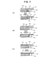
- the thickness of the cutting portion is preferably as follows. As shown in Fig. 7(A) , in case where a thickness 144 of a cavity 143 formed by an upper mold 141 and a lower mold 142 at the time of mold closing is predetermined such as that in particular in RTM and the like, a thickness 146 of the actually cut portion (cutting end portion) of a preform 145 is preferably smaller than the cavity thickness 144, and further preferably smaller by 0.05 mm or more.
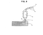
- a laser ray 71 is introduced into a laser head 72 irradiating the laser lay 71 through an optical fiber 73, and an inert gas 76 such as nitrogen gas is introduced into the laser head 72 through an inert gas supply line 74, and at the time irradiating the laser ray 71 toward a preform 75, preferably the inert gas 76 is injected toward the cutting position of the preform 75 at the same time. At that time, it is preferred that the inert gas is injected coaxially with the laser ray 71.
- the pressure (gas pressure) in a laser head 81 is kept to be higher in pressure than that outside the laser head 81.
- soot 84 is generated by sublimation of the structural material of preform 82 and the soot 84 rises up to the irradiation port side of laser head 81. If the high pressure condition in the head is kept as described above, entering into the head 81 of this soot 84 can be prevented. However, if the pressure in the head is low, as shown by the dashed line in Fig.
- soot 85 enters into head 81.
- a method may be employed wherein, while the inside of a laser head 86 is made high in pressure, an inert gas is introduced into the laser head 86 through inert gas supply line 74 similarly to that shown in Fig. 8 , the inert gas 76 is injected toward the cutting position of preform 82 together with the irradiation of laser ray 83.
- entering of soot 84 into laser head 86 can be suppressed, and clogging of the head 86 can be prevented.
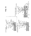
- soot generated as described above can be prevented from entering into laser head 86 by injecting inert gas 76 supplied from inert gas supply line 74 toward preform 82 together with the irradiation of laser ray 83 as shown in Fig. 10(A)
- inert gas supply line 74 supplied from inert gas supply line 74 toward preform 82 together with the irradiation of laser ray 83 as shown in Fig. 10(A)
- it is preferred to positively remove the soot 84 and as an effective means, removal by suction is exemplified. As shown in Fig.
- a structure can also be employed wherein a skirt for suction 91 is attached to the lower portion of laser head 86, soot 84 is gathered in this skirt for suction 91, and the soot 84 is sucked and removed by a vacuum pump 93 through a suction line 92 communicating with the skirt 91.
- a structure can be employed wherein a suction line 96 communicating with the upper surface side of a corrugated bed 95 supporting receiving jigs 94 from their lower surface sides is provided, and soot 84 is sucked and removed by a vacuum pump 97.
- a laminate structure which is formed by integrating fabric materials each provided with a particle-like resin on at least one surface with each other by adhesion via the resin.
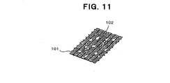
- the figure shows a state where particle-like resin 102 for adhesion is scattered on a carbon fiber fabric 101 (in the example shown in the figure, it is a unidirectional carbon fiber woven fabric), and the laminate can be formed by stacking and integrating such fabric materials with each other.
- a laminate for example, in case where a preform is formed as a three-dimensional shape, is effective for maintaining the formed shape at a good condition.
- a three-dimensional preform 112 is conveyed by an articulated robot 111, and even in case where it is placed on a treatment table 115 of a cutting apparatus 114 using a laser ray 113, the predetermined three-dimensional shape thereof can be easily maintained.
- laser ray 113 is irradiated from a laser head 117 attached to the tip portion of another articulated robot 116, the laser ray is introduced to laser head 117 from an optical fiber 118, and a suction line 120 by a vacuum pump 119 is connected to the head 117.
- Suction line 120 by vacuum pump 119 is sucked via a filter 121, drain 122 is stored at the lower part side thereof, and drain 122 is appropriately discharged by opening/closing of a valve 123.
- a pressurized air line 124 is connected to treatment table 115, and it is served to mold opening and cleaning.
- a vacuum suction line 125 is connected thereto, and it is served to vacuum cramping of three-dimensional preform 112, the aforementioned soot suction and removal, suction and removal of chip generated at the time of laser cutting, etc.
- a drain line 126 such as one described above, a three way electromagnetic valve 127 for switching the direction for treatment, a filter 128, etc. are provided.
- An inert gas supply line 129, a cooling water forward line 130, a cooling water return line 131, etc. are communicated with articulated robot 116.
- the method for cutting a carbon fiber substrate according to the present invention can be applied to cutting of any substrate or preform comprising a carbon fiber fabric material.
Landscapes
- Engineering & Computer Science (AREA)
- Physics & Mathematics (AREA)
- Optics & Photonics (AREA)
- Plasma & Fusion (AREA)
- Mechanical Engineering (AREA)
- Textile Engineering (AREA)
- Chemical & Material Sciences (AREA)
- Chemical Kinetics & Catalysis (AREA)
- General Chemical & Material Sciences (AREA)
- Laser Beam Processing (AREA)
- Treatment Of Fiber Materials (AREA)
Abstract
Description
- The present invention relates to a method for cutting a carbon fiber substrate formed from a fabric material comprising carbon fibers, and specifically, to a method for cutting a carbon fiber substrate suitable in use for cutting a substrate, used for making a fiber reinforced plastic (hereinafter, also referred to as "FRP"), precisely at a predetermined shape.
- Recently, for lightening in weight an airplane, an automobile, etc., opportunity for employing a fiber reinforced plastic used with carbon fibers (hereinafter, also referred to as "CFRP") has increased. For example, a CFRP using a carbon fiber woven fabric as a reinforcing fiber substrate, in which used are carbon fiber bundles each comprising a plurality of carbon fibers arranged in one direction, is very advantageous in specific stiffness and specific strength as compared with metal materials, and it is employed for various parts.
- As a process for molding such a CFRP, various processes are proposed such as prepreg/auto clave process, RTM (Resin Transfer Molding) process, RFI (Resin Film Infusion) process, processes from derived therefrom, etc. Among these processes, RTM process is paid attention to from a viewpoint of being able to obtain a CFRP having a complicated shape, for example, by preparing a carbon fiber substrate formed from a fabric material comprising carbon fibers or a laminate stacked with a plurality of the fabric materials, forming a preform with a predetermined shape in advance, and impregnating a matrix resin injected into a mold into the preform and curing the resin.
- However, in case where it is tried to cut the fabric or the laminate thereof comprising carbon fibers, or the preform formed therewith at a predetermined shape in advance (hereinafter, these are also called as a "carbon fiber substrate" as a generic term), into a predetermined shape by using a usual cutter, the following problems may occur. Namely, because a carbon fiber is very thin to be about 10 µm in diameter, in case where it is tried to cut the laminate of carbon fiber fabrics or the preform thereof by a cutter at a contact condition, the portion to be cut is cut at a condition being crushed, also because of the hardness of carbon fiber itself. Therefore, by the repelling power, the carbon fibers are liable to be frayed at a cutting end surface. In particular, when the cutting is tried after laminating fabrics and forming the preform, the cutting surface is liable to become uneven in the thickness direction.
- If such a preform is tried to be disposed into a mold, a mismatch may occur between it and a cavity shape of the mold. In case where the preform is larger than the mold, it is to be performed to conduct an additional cutting processing operation for adjusting the shape to a size fitting to the mold, or to perform molding by containing the preform larger than the mold in the mold as it is. In the latter case, carbon fibers are contained up to a flash portion of CFRP after molding, and there occurs an inconvenience that the flash removing operation becomes troublesome. On the other hand, in case where the preform is smaller, because a portion of only resin (resin rich portion) is formed in a gap between the preform and the mold, an operation for charging carbon fibers separately becomes necessary before injection of matrix resin. Further, even if the shapes of the preform and the mold almost coincide with each other, an end portion of the preform may be frayed, for example, when the preform is transferred to the mold, and therefore, it is difficult to completely suppress the mismatch.
- For such carbon fibers easy to be frayed, a technology is known wherein carbon fibers are to be bound with one another. For example, as a technology for binding carbon fibers, a process for obtaining a sheet-like molded material from carbon fibers formed as short fibers (about 3-20 mm) via a phenolic resin and the like is described in
Patent document 1 andPatent document 2. As a method for making this sheet-like molded material, a method is described wherein short carbon fibers are dispersed randomly in a two-dimensional plane, and they are calcined together with the phenolic resin in an inert atmosphere at a high temperature of about 200°C or higher. The sheet-like molded material described in these documents is used suitably for a carbon fiber electrode, and it is not used by additionally impregnating a matrix resin into the sheet-like molded material. Further, since the whole of the short carbon fibers themselves are carbonized because of the calcination at a high temperature of about 200°C or higher, the elastic modulus, the strength, etc. of the short carbon fibers themselves cannot be exhibited. -
- Patent document 1:
JP-A-2004-288489 - Patent document 2:
JP-A-2005-297547 - In order solve the problem as aforementioned that the cutting end surface is liable to be frayed and the carbon fiber substrate is hard to be precisely cut at a predetermined shape when the substrate is cut using a usual cutter, although it is still not published, by the applicant of the present application, a technology is proposed wherein by generating a specified-nature graphitized portion (for example, membrane-like graphitized portion) on the cutting end surface, while achieving an easy cutting to a predetermined shape, fraying of carbon fibers at the cutting end surface and the like can be prevented (Japanese Patent Application No.
2000-285882 - However, it has become clear that there remain the following problems in case the carbon fiber substrate is thus cut by a laser. First, in a laser processing, because the sublimation cutting temperature of carbon fibers is about 3,800°C to be higher than that of a metal (about 1,600°C in case of iron) and a difference between an atmosphere temperature and the cutting temperature is great, the thermal energy is liable to be dissipated. Although the thermal conductivity of carbon fiber itself is higher than that of a general inorganic substance, depending upon the formation of a substrate formed from a fabric material, because there is a case where the thermal conductivity of the substrate in a cutting processing direction, that is, a thickness direction (especially, a thickness direction of a substrate comprising a laminate) becomes extremely low as compared with that of a metal, heat supply through the substrate itself in the thickness direction is hardly achieved, and it may become difficult to reach the cutting temperature of the substrate. If the cutting temperature by a laser is not sufficiently elevated, namely, if it is not elevated up to the sublimation cutting temperature of carbon fibers, a cutting defective place may occur.
- Further, in the laser cutting, there is a focal distance capable of processing (a focal distance for convergence), and in case where the substrate is one easy to be deformed, there is a fear that the portion to be cut may shift from the range of the focal distance capable of processing and it shifts, a cutting defective place also may occur.
- Accordingly, in order to solve the above-described problems when the carbon fiber substrate is cut by a laser and other problems accompanying with the laser cutting, an object of the present invention is to provide a method for cutting a carbon fiber substrate capable of performing a laser cutting, that can expect an excellent cutting performance and an excellent cutting end surface form as aforementioned for cutting of a carbon fiber substrate, stably at a target desired condition.
- To achieve the above-described objects, a method for cutting a carbon fiber substrate according to the present invention is characterized in that, when a carbon fiber substrate configured from a fabric material comprising at least carbon fibers is cut with a laser, the substrate is cut at initial conditions which have been set so that the state of the substrate that is being cut with the laser can be suppressed with or prevented from deviating from a target state.
- Where, the carbon fiber substrate configured from a fabric material comprising at least carbon fibers in the present invention includes a carbon fiber substrate configured from substantially any fabric material comprising carbon fibers, and includes both of the fabric material as a single material and a laminate. Further, as the formation of the fabric material, for example, a unidirectional woven fabric substrate arranging carbon fibers in one direction, a multiaxial stitched substrate, and formation such as a non-woven fabric, a plain weave, a twill weave, knitting or a braid, are included, and further, a hybrid configuration with glass fibers or organic fibers may be employed. Further, in case of a substrate having a laminate configuration, except a fabric material comprising carbon fibers, a fabric material comprising glass fibers, aramide fibers, PBO (polyparaphenylene benzobisoxazol) fibers, boron fibers, alumina fibers, etc. may be contained. Then, a preform wherein such a substrate is formed in advance in a predetermined shape (including both two and three dimensional shapes) is also included as a carbon fiber substrate according to the present invention. As a preferable formation of the above-described substrate, a substrate configured from the above-described carbon fiber containing fabric material comprising carbon fibers of continuous fibers is raised, and more preferably, a carbon fiber containing fabric material comprising only carbon fibers is raised. Moreover, although the present invention mainly targets a so-called dry carbon fiber substrate into which a resin (matrix resin) is not impregnated, a substrate into which a resin is impregnated, for example, a prepreg into which a resin is impregnated at a condition of so-called B-stage before being cured, is also included in the carbon fiber substrate according to the present invention.
- In such a method for cutting a carbon fiber substrate according to the present invention, specified initial conditions capable of suppressing with or preventing from deviating from a target state as the state of the substrate at the time of being cut with the laser are set, and under the conditions the substrate is cut. This suppressing with or preventing from deviating from a target state means suppressing or preventing undesired dissipation of heat due to the laser for cutting as aforementioned, preventing shifting from the range of the laser focal distance capable of processing a portion of the substrate to be cut, further, suppressing or preventing clogging of a head for irradiating the laser, etc. By setting initial conditions capable of suppressing or preventing deviating or shifting from a target state for the state at the time of cutting the substrate with the laser, an undesired state at the time of cutting can be avoided, and the cutting of the substrate with the laser can be performed stably at a desired target state.
- As a more concrete embodiment, a method can be employed wherein, when the carbon fiber substrate is cut with the laser at a condition being placed on a receiving jig, the substrate is partially received by the receiving jig. This is to realize a form where the heat is hardly dissipated at the time of laser cutting by partially receiving the substrate by the receiving jig basically at a portion in which the heat transfer from the substrate hardly occurs. Namely, as aforementioned, the sublimation cutting temperature of carbon fibers is about 3,800°C to be higher than that of a metal, and because a difference between an atmosphere temperature and the cutting temperature is great, thermal energy is liable to be dissipated. Further, because thermal conductivity in a cutting processing direction, that is, a thickness direction of the substrate, is low as compared with that of a metal, heat supply through the substrate itself in the thickness direction is hardly achieved, and there is a feature that the temperature at a portion to be cut in the thickness direction hardly reaches the cutting temperature. Therefore, in cutting of such a substrate comprising carbon fibers, it is necessary to greatly suppress the dissipation of thermal energy, and a jig structure becomes important which can set parameters relating to dissipation of thermal energy (thermal conductivity, contact area, temperature difference with a contact object, time for heating, etc. are in proportion to the amount of dissipation, and distance with a contact object is in inverse proportion thereto.) at adequate ranges. Further, instead of dissipation of thermal energy, or depending upon dissipation of thermal energy, if the thermal capacity of the jig brought into contact with the substrate to be cut is set as small as possible, the jig is elevated in temperature in a short time, and the dissipation of thermal energy may be prevented.
- In such a structure, more concretely, it is preferred that a cutting position of the substrate is set at a position where the substrate is not brought into contact with the above-described receiving jig. In order to prevent the thermal energy irradiated to the carbon fiber substrate from dissipating through the receiving jig, it is better to set the distance between the receiving jig and the cutting point great. Namely, it is better not to receive the back surface of the cutting line. On the other hand, if the distance with the cutting point is too great, because the substrate is liable to deflect and to shift from the focal length range, it is required to be set at an adequate distance. For example, as a preferable range of the distance, ranges of 1 mm to 200 mm, 2mm to 100 mm, and further, 3 mm to 75 mm, can be exemplified. Where, since the rigidity increases if the thickness of the substrate increases, the maximum distance can also be increased depending upon the thickness. Further, the dissipation of thermal energy through the receiving jig is more remarkable at a substrate receiving position in the fiber extending direction (thermal conductivity is high in this direction), and therefore, the distance between the receiving jig and the cutting point may be changed depending upon the direction of fiber. For example, in a woven fabric substrate such as a cloth material, the receiving jig may be disposed under a fiber bundle extending in a direction so as not to directly come into contact with fibers present on the cutting line.
- Further, it is also preferred that a contact supporting portion of the receiving jig relative to the substrate is set at a strip-like, linear or dot-like form. If the substrate is supported by such a contact supporting portion, the contact area between the receiving jig and the substrate can be surely reduced, and the undesired thermal dissipation can be surely decreased.
- Moreover, it is also preferred that a contact surface to the substrate of the receiving jig is formed from a material having at least a heat insulation property. In such a structure, the thermal conductivity between the substrate and the receiving jig can be reduced, and the undesired thermal dissipation can be decreased more securely.
- Further, in the method for cutting a carbon fiber substrate according to the present invention, it is preferred that , when the carbon fiber substrate is cut with the laser at a condition being placed on a receiving jig, the substrate is supported by the receiving jig at both sides of a cutting position. In order to cut the substrate efficiently and quickly, it is desired that the position of the substrate to be cut does not shift from a predetermined range of the laser focal distance. A carbon fiber substrate, especially, a dry substrate into which a resin is not impregnated, has a relatively high flexibility, and it is easily deflected. Therefore, in order to prevent the cutting point from shifting from a predetermined range of laser focal distance due to occurrence of a large deflection, the substrate is supported at both sides of the cutting position, and a two-sided supporting condition is realized to suppress the deflection small. In particular, because an end portion of the substrate is liable to hang down and an interlayer portion is liable to be delaminated in case of a laminate substrate, in case where the end portion is cut, it is preferred to support the substrate by the receiving jig at both sides of the cutting position. In order to support and fix the substrate more securely at at least one portion among the portions at both sides of the cutting position, for example, a vacuum attraction function may be provided to the receiving jig. Further, the substrate may be held from both surface sides at at least one portion. For holding from both surface sides, for example, a magnetic force may be utilized, and a mechanical-type holding may also be employed.
- Further, in the method for cutting a carbon fiber substrate according to the present invention, although a laser head is used for irradiating a laser, there is a fear that soot as a sublimation substance of the substrate from the cutting portion may enter into this laser head and it may cause clogging of the laser irradiating route. In order to remove such a fear, it is preferred that a gas (as a preferable gas, an inert gas, for example, nitrogen gas, is exemplified.) is injected together with irradiation of laser from inside of the laser head. In order to effectively prevent entering or adhesion of soot, it is preferred that this gas is injected coaxially with irradiated laser. Further, in order to prevent soot from entering into the laser head from outside, it is preferred that inside of the laser head is kept at a condition higher in pressure than outside of the laser head.
- Furthermore, it can also be done to remove the soot more positively. For example, a method may also be employed wherein a suction means is provided to the laser head, and soot generating at the time of cutting the substrate is sucked. Because the soot rises upward, it is preferred that the suction port of the suction means is disposed at a position including a height portion of the cutting point or higher. Further, when the gas is injected, because the soot is blown to the back surface side of the substrate more or less, it is more preferable to provide a suction port also at the back surface side (avoiding the laser ray).
- Further, in the method for cutting a carbon fiber substrate according to the present invention, as aforementioned, as the carbon fiber substrate to be cut, a form of a laminate and a form of a preform, which is formed in a predetermined shape in advance, are both targeted. In case of the form of a laminate, it is preferably a laminate formed by integrating fabric materials each provided with a particle-like resin on at least one surface with each other by adhesion via the resin. By such an integration by adhesion via the resin, a predetermined laminate structure hardly collapses, and a formed shape may be kept even if formed as a preform.
- Thus, in the method for cutting a carbon fiber substrate according to the present invention, when the carbon fiber substrate is cut by a laser, it becomes possible to effectively solve various problems such as dissipation of heat, shift from a range of laser focal length and soot, and the cutting of the carbon fiber substrate can be performed stably at desired target conditions.
-
- [
Fig. 1] Fig. 1 depicts schematic diagrams showing a method for cutting a carbon fiber substrate according to an embodiment of the present invention. - [
Fig. 2] Fig. 2 depicts schematic diagrams showing respective embodiments for a receiving jig in the present invention. - [
Fig. 3] Fig. 3 depicts schematic diagrams showing a method for cutting a carbon fiber substrate according to another embodiment of the present invention. - [
Fig. 4] Fig. 4 depicts schematic diagrams showing other respective embodiments for a receiving jig in the present invention. - [
Fig. 5] Fig. 5 depicts schematic diagrams showing problems generatable in case of supporting at both sides (A) and in case of supporting at one side (B) by a receiving jig in the present invention. - [
Fig. 6] Fig. 6 depicts schematic diagrams showing a problem generatable in case of merely supporting at both sides by a receiving jig (A) and a problem generatable in case of holding a substrate at both surfaces (B) in the present invention. - [
Fig. 7] Fig. 7 depicts schematic diagrams exemplifying respective states at the time of closing a mold that occur in accordance with relationship in size between an actual thickness of a cutting portion and a thickness of a cavity of the mold in the present invention. - [
Fig. 8] Fig. 8 is a schematic diagram showing an example of laser cutting accompanying with inert gas injection in the present invention. - [
Fig. 9] Fig. 9 depicts schematic diagrams exemplifying a problem of soot and treatment method thereof in the present invention. - [
Fig. 10] Fig. 10 depicts schematic diagrams exemplifying another problem of soot and treatment methods thereof in the present invention. - [
Fig. 11] Fig. 11 is a partial perspective view showing an example of a fabric material provided with particle-like resin in the present invention. - [
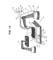
Fig. 12] Fig. 12 is a schematic diagram showing an example of a process including cutting of a three-dimensional preform in the present invention. - Hereinafter, desirable embodiments of the present invention will be explained referring to figures.
Fig. 1 shows a method for cutting a carbon fiber substrate according to an embodiment of the present invention, in particular, shows an example for cutting a circumferential edge portion of a preform, formed as a laminate of fabric materials comprising carbon fibers, with a laser. As shown inFig. 1 (A) , apreform 1 is placed on a receivingjig 2, and cutting with a laser is performed along a cutting line (a cutting position 3) extending along the circumferential edge ofpreform 1. As shown inFig. 1(B) , in this embodiment, receivingjig 2 is provided on abead 5 formed as a corrugated plate on a base 4, andpreform 1 is placed on this receivingjig 2.Preform 1 is partially received by receivingjig 2, and receivingjigs jig 2b,preform 1 is held from both surface sides using apressing jig 6. - A
laser ray 8 for cutting is irradiated from alaser head 7 toward cuttingposition 3, and by movinghead 7 or base 4, the laser cutting is performed along the cutting line shown inFig. 1 . Cuttingposition 3 is set at a position wherepreform 1 does not come into contact with receiving jig 2 (a position between receivingjigs Laser ray 8 irradiated fromlaser head 7 is introduced intohead 7 through anoptical fiber 9, it is converged at a condition where the focal length is adjusted at the cutting portion ofpreform 1 in its thickness direction, and it is served to cutting. In order to suppress overheat ofhead 7, in laser head 7 a cooling water is circulated through a coolingwater forward line 10 and a coolingwater return line 11. Further, in this embodiment, in order to prevent clogging of the inside of head and the like ascribed tosoot 12 generated at the time of cutting, an inert gas (for example, nitrogen gas) supplied from an inertgas supply line 13 is injected toward cuttingposition 3 throughhead 7 at a coaxial condition withirradiated laser ray 8. Further, a bell-like suction case 14 spreading downward is provided onlaser head 7, andsoot 12 rising from cuttingposition 3 is gathered insuction case 14, and is removed by suction through asuction line 16 by a suction device such as avacuum pomp 15. - In the cutting of
preform 1 using such a device, sincepreform 1 does not come into contact with receivingjig 2 at cuttingposition 3 bylaser ray 8, dissipation of heat required for the cutting is suppressed. Further, becausepreform 1 is supported by receivingjigs position 3, shift of the cutting position from a proper laser length range oflaser ray 8 ascribed to deflection ofpreform 1 can be avoided, and predetermined desired cutting conditions can be maintained. Furthermore, because the inert gas is supplied and injected intolaser head 7 andsoot 12 is adequately sucked and removed, clogging oflaser head 7 can be prevented, and desired laser cutting conditions can be maintained stably. -
Fig. 2 shows respective embodiments when a preform provided as a carbon fiber substrate is received by a receiving jig in the present invention. In the embodiment shown inFig. 2(A) , apreform 21 is received by a plurality of strip-like receiving jigs 22 as described above, and the cutting position is set between receivingjigs 22. In the embodiment shown inFig. 2(B) ,preform 21 is received by a plurality of receivingjigs 23 standing in pin-like shapes, and by receiving at a condition of dot-like contact, the contact area is reduced for suppressing dissipation of heat. In the embodiment shown inFig. 2(C) ,preform 21 is received by a receivingjig 24 comprising a corrugated plate formed in a zigzag shape in cross section, and by receiving at a condition of linear contact, the contact area is reduced for suppressing dissipation of heat. In the embodiment shown inFig. 2(D) , a plurality of strip-like receiving jigs 22 and receivingjig 24 comprising a corrugated plate are combined, preform 21 is received by the plurality of strip-like receiving jigs 22, and receivingjig 24 comprising a corrugated plate functions as not a jig directly receivingpreform 21 but a bed as shown inFig. 1 . By forming this bed as a corrugated plate structure, heat transfer through the receivingjig 22 toward the bed or the base side is suppressed, and dissipation of heat in the laser cutting is suppressed. In the embodiment shown inFig. 2(E) ,preform 21 is received by a well crib-like or lattice-like receiving jig 25, and the contact area is also reduced for suppressing dissipation of heat. -
Fig. 3 shows a case where the cutting position comprises a plurality of cuttingpositions Fig. 1 , and depending upon these cuttingpositions contact portions 33 andnon-contact portions 34 ofpreform 1 with a receivingjig 32 are adequately set. Thus, in accordance with the positions and the number thereof to be cut inpreform 1, it is possible to appropriately set the divisional form and the like of receivingjig 32. Because other structures are similar to those shown inFig. 1 , the explanation will be omitted by allotting the same symbols to those structures as those inFig. 1 . -
Figs. 4 (A) to (D) exemplify embodiments employing heat insulation material structures as compared with the embodiments shown inFigs. 2(A) to (D) . In the embodiment shown inFig. 4(A) ,preform 21 is received by a receivingjig 41 having a shape similar to that shown inFig. 2(A) , and receivingjig 41 itself is composed of a heat insulation material, or a layer of aheat insulation material 42 is provided on the surface of receivingjig 41. By interposing such aheat insulation material 42, dissipation of heat in the laser cutting is suppressed more efficiently. In the embodiment shown inFig. 4(B) ,preform 21 is received by a plurality of receivingjigs 43 stood in pin-like shapes similar to those shown inFig. 2(B) , and a surface-layerheat insulation material 44 is provided on each receivingjig 43. By providing such a surface-layerheat insulation material 44, dissipation of heat in the laser cutting is suppressed more efficiently. In the embodiment shown inFig. 4(C) ,preform 21 is received by a receivingjig 45 comprising a corrugated plate formed in a zigzag shape in cross section similar to that shown inFig. 2(C) , and by interposing aheat insulation material 46 at the peaks of the zigzag shape which are contact portions of receivingjig 45 withpreform 21, dissipation of heat in the laser cutting is suppressed more efficiently. In the embodiment shown inFig. 4(D) , a plurality of strip-like receiving jigs 47 and receivingjig 48 comprising a corrugated plate are combined similarly in the structure shown inFig. 2(D) , and by interposing aheat insulation material 49 at the side of the contact portion of strip-like receiving jig 47 brought into contact withpreform 21, dissipation of heat in the laser cutting is suppressed more efficiently. Further, the method for interposing the above-described heat insulation material is a method for dividing a heat insulation function from the functions required for the receiving jig, and for example, if the frame of a receiving jig is composed of a metal and a glass fiber woven fabric and the like which forms a thin heat insulation layer is attached as the surface layer, the positioning of the preform and the heat insulation at the time of processing can both stand and such a structure can be employed preferably. - As aforementioned, the cutting position in the thickness direction of the substrate must be in an adequate range of laser focal length. In order to achieve this, the deflection of the carbon fiber substrate at the cutting position must be suppressed as small as possible. In particular, in case where the cutting position is present at the end portion of the substrate, it is necessary to pay attention to the amount of deflection of the substrate.
-
Fig. 5 exemplifies with respect to methods for suppressing the deflection of a preform as a carbon fiber substrate to be small.Fig. 5(A) shows an embodiment wherein receivingjigs 53 are disposed at both sides of acutting position 52 of apreform 51, and in case where alaser ray 56 sent from anoptical fiber 54 to alaser head 55 is irradiated,laser ray 56 has a certain focal length, and the vicinity of the focus thereof becomes a range capable of cutting 57 in the thickness direction ofpreform 51. If the portion to be cut in the thickness direction ofpreform 51 gets out of this range capable of cutting 57 by deflection and the like, there is a fear that a cutting defective portion or a portion being not cut may occur. In order to prevent such an undesired deflection ofpreform 51, the receivingjigs 53 are disposed at both sides of cuttingposition 52 and the distance betweenjigs 53 must be adequately set. For apreform 51 which is liable to be deflected, it is necessary to set a relatively small distance. Then, in order to holdpreform 51 at receivingjigs 53 present at both sides more securely, as shown in the figure, it is preferred that a suction means 58 capable of attractingpreform 51 is provided. More preferably, as shown in the figure, it is preferred that respective suction means 58 are provided for receivingjigs 53 present at both sides. However, when a partial cutting in the thickness direction of the preform is required, it can also be done to produce a partially cut preform by intentionally shifting the focus. - In case where the end portion of preform is cut with a laser, there is a case where it is difficult to support the portions at both sides of the cutting position and a support at one side is inevitably employed. In such a case, for example, as shown in (B-1) of Fig. (B), although a hanging 59a or an
interlayer delamination 59b in case of a laminate is liable to occur, and in such a case, as shown in (B-2) of Fig. (B), if a portion shifting from the range capable of cutting occurs inpreform 51, there is a possibility that a portion being not cut 60a or 60b may occur in the portion. Therefore, in case where the end portion ofpreform 51 is cut with a laser, to the utmost, supporting at both sides of the cutting position is desired. - Further, as shown in
Fig. 6(A) , when cutting is performed at a condition where apreform 61 is merely received by a receivingjig 63 from the lower side at both sides of acutting position 62 ofpreform 61, in case where a deflection 66 (a hanging) is liable to occur inpreform 61, or in case where, when aninert gas 65 is injected from alaser head 64 as aforementioned, adeflection 67 occurs inpreform 61 at the cuttingposition 62 by the pressure of the injection, and the like, there is a fear of getting out of the range capable of cutting determined around the focal length of the laser ray. In such a case, as shown inFig. 6(B) , it is preferred that, by a structure wherein at least one of receivingjigs 63 provided at both sides of cuttingposition 62 ofpreform 61 holds thepreform 61 from both surface sides, the deflection ofpreform 61 is suppressed to be small within a range capable of cutting 68. In this case, as shown in the left-hand part ofFig. 6(B) , a mechanical cramping is possible, and as shown as receivingjigs 69 at the right-hand part, a structure can also be employed wherein receivingjigs 69 at both surface sides are attracted to each other by utilizing a magnetic force. - Further, in case where the preform is held from the both surface sides as described above, the thickness of the cutting portion is preferably as follows. As shown in
Fig. 7(A) , in case where athickness 144 of acavity 143 formed by anupper mold 141 and alower mold 142 at the time of mold closing is predetermined such as that in particular in RTM and the like, athickness 146 of the actually cut portion (cutting end portion) of apreform 145 is preferably smaller than thecavity thickness 144, and further preferably smaller by 0.05 mm or more. In such a structure, for example, in case where a specified-nature membrane-likegraphitized portion 147 is generated on the cutting end surface and fraying of carbon fibers and the like on the cutting end surface is prevented as aforementioned (in case where the technology previously proposed in Japanese Patent Application No.2000-285882 graphitized portion 147 at the time of mold closing. As shown inFig. 7(B) , in case where athickness 149 of the actually cut portion of apreform 148 is greater than the above-describedcavity thickness 144, there is a fear that, at the time of mold closing, a bad influence may be given to a specified-nature membrane-likegraphitized portion 150 generated on the cutting end surface (for example, in the embodiment depicted in the figure, the membrane-likegraphitized portion 150 may be damaged, or destroyed). Further, as shown inFig. 7(C) , in case where the above-describedcavity thickness 144 and athickness 152 of the actually cut portion of apreform 151 almost coincide with each other, a formation is achieved wherein a membrane-likegraphitized portion 153 is held by upper andlower molds graphitized portion 153 and the mold, and the resin is liable to be cracked from the position of the membrane-likegraphitized portion 153 formed as a trigger point. - Further, in the cutting method according to the present invention, in order to stably irradiate a laser at a predetermined condition, clogging in the laser head must be prevented. For this, as shown in
Fig. 8 , alaser ray 71 is introduced into alaser head 72 irradiating the laser lay 71 through anoptical fiber 73, and aninert gas 76 such as nitrogen gas is introduced into thelaser head 72 through an inertgas supply line 74, and at the time irradiating thelaser ray 71 toward apreform 75, preferably theinert gas 76 is injected toward the cutting position of thepreform 75 at the same time. At that time, it is preferred that the inert gas is injected coaxially with thelaser ray 71. - In case where the inert gas cannot be supplied and injected as described above, as shown in
Fig. 9(A) , it is preferred that the pressure (gas pressure) in alaser head 81 is kept to be higher in pressure than that outside thelaser head 81. In case where apreform 82 is cut with alaser ray 83, there is a case wheresoot 84 is generated by sublimation of the structural material ofpreform 82 and thesoot 84 rises up to the irradiation port side oflaser head 81. If the high pressure condition in the head is kept as described above, entering into thehead 81 of thissoot 84 can be prevented. However, if the pressure in the head is low, as shown by the dashed line inFig. 9(A ), there is a fear thatsoot 85 enters intohead 81. In such a case, as shown inFig. 9(B) , a method may be employed wherein, while the inside of alaser head 86 is made high in pressure, an inert gas is introduced into thelaser head 86 through inertgas supply line 74 similarly to that shown inFig. 8 , theinert gas 76 is injected toward the cutting position ofpreform 82 together with the irradiation oflaser ray 83. In such a method, entering ofsoot 84 intolaser head 86 can be suppressed, and clogging of thehead 86 can be prevented. - Although the soot generated as described above can be prevented from entering into
laser head 86 by injectinginert gas 76 supplied from inertgas supply line 74 towardpreform 82 together with the irradiation oflaser ray 83 as shown inFig. 10(A) , on the other hand, there is a fear that thesoot 84 spreads around the cutting position together with the flow of the injectedinert gas 76. In order to prevent such spreading ofsoot 84, it is preferred to positively remove thesoot 84, and as an effective means, removal by suction is exemplified. As shown inFig. 10(B) , a structure can also be employed wherein a skirt forsuction 91 is attached to the lower portion oflaser head 86,soot 84 is gathered in this skirt forsuction 91, and thesoot 84 is sucked and removed by avacuum pump 93 through asuction line 92 communicating with theskirt 91. - Furthermore, as shown in
Fig. 10(C) , there is a case where, immediately after the cutting at a predetermined cutting position ofpreform 82 has been completed,laser ray 83 goes throughpreform 82 in its thickness direction andinert gas 76 is also injected up to the back surface side ofpreform 82. In such a condition, becausesoot 84 is generated also on the back surface side ofpreform 82, as shown inFig. 10(C) , it is preferred to provide a suction means also on the back surface side. For example, a structure can be employed wherein asuction line 96 communicating with the upper surface side of acorrugated bed 95 supporting receivingjigs 94 from their lower surface sides is provided, andsoot 84 is sucked and removed by avacuum pump 97. - As aforementioned, as a carbon fiber substrate to be cut, a laminate structure can be employed which is formed by integrating fabric materials each provided with a particle-like resin on at least one surface with each other by adhesion via the resin. Namely, as shown in
Fig. 11 , the figure shows a state where particle-like resin 102 for adhesion is scattered on a carbon fiber fabric 101 (in the example shown in the figure, it is a unidirectional carbon fiber woven fabric), and the laminate can be formed by stacking and integrating such fabric materials with each other. Such a laminate, for example, in case where a preform is formed as a three-dimensional shape, is effective for maintaining the formed shape at a good condition. - If the three-dimensional shape of a preform can be maintained, the conveying and various treatments of the preform are facilitated. For example, as shown in
Fig. 12 , a three-dimensional preform 112 is conveyed by an articulatedrobot 111, and even in case where it is placed on a treatment table 115 of acutting apparatus 114 using alaser ray 113, the predetermined three-dimensional shape thereof can be easily maintained. In the example shown inFig. 12 ,laser ray 113 is irradiated from alaser head 117 attached to the tip portion of another articulatedrobot 116, the laser ray is introduced tolaser head 117 from anoptical fiber 118, and asuction line 120 by avacuum pump 119 is connected to thehead 117.Suction line 120 byvacuum pump 119 is sucked via a filter 121, drain 122 is stored at the lower part side thereof, and drain 122 is appropriately discharged by opening/closing of avalve 123. - Further, a
pressurized air line 124 is connected to treatment table 115, and it is served to mold opening and cleaning. Further, avacuum suction line 125 is connected thereto, and it is served to vacuum cramping of three-dimensional preform 112, the aforementioned soot suction and removal, suction and removal of chip generated at the time of laser cutting, etc. To thissuction line 125, adrain line 126 such as one described above, a three wayelectromagnetic valve 127 for switching the direction for treatment, afilter 128, etc. are provided. An inertgas supply line 129, a cooling waterforward line 130, a coolingwater return line 131, etc. are communicated with articulatedrobot 116. - The method for cutting a carbon fiber substrate according to the present invention can be applied to cutting of any substrate or preform comprising a carbon fiber fabric material.
-
- 1, 21, 51, 61, 75, 82: preform
- 2, 2a, 2b, 22, 23, 24, 25, 32, 41, 43, 45, 47, 48, 53, 63, 69, 94: receiving jig
- 3, 31a, 31 b, 52, 62: cutting position
- 4: base
- 5, 95: bed
- 6: pressing jig
- 7, 55, 64, 72, 81, 86, 117: laser head
- 9, 54, 73, 118: optical fiber
- 10, 130: cooling water forward line
- 11, 131: cooling water return line
- 12, 84, 85: soot
- 13, 74, 129: inert gas supply line
- 14: suction case
- 15, 93, 97, 119: vacuum pump
- 16, 92, 96, 120, 125: suction line
- 33: contact portion
- 34: non- contact portion
- 42, 44, 46, 49: heat insulation material
- 57, 68: range capable of cutting
- 58: suction mechanism
- 59a: hanging
- 59b: interlayer delamination
- 60a, 60b: portion being not cut
- 65, 76: inert gas
- 66, 67: deflection
- 91: skirt for suction
- 101: carbon fiber fabric
- 102: particle-like resin
- 111, 116: articulated robot
- 112: three-dimensional preform
- 114: cutting apparatus
- 115: treatment table
- 121, 128: filter
- 122: drain
- 123: valve
- 124: pressurized air line
- 126: drain line
- 127: three way electromagnetic valve
- 141: upper mold
- 142: lower mold
- 143: cavity
- 144: cavity thickness
- 145, 148, 151: preform
- 146, 149, 152: thickness of cut portion
- 147, 150, 153: membrane-like graphitized portion
Claims (13)
- A method for cutting a carbon fiber substrate characterized in that, when a carbon fiber substrate configured from a fabric material comprising at least carbon fibers is cut with a laser, said substrate is cut at initial conditions which have been set so that the state of said substrate that is being cut with said laser can be suppressed with or prevented from deviating from a target state.
- The method for cutting a carbon fiber substrate according to claim 1, wherein, when said carbon fiber substrate is cut with said laser at a condition being placed on a receiving jig, said substrate is partially received by said receiving jig.
- The method for cutting a carbon fiber substrate according to claim 2, wherein a cutting position of said substrate is set at a position where said substrate is not brought into contact with said receiving jig.
- The method for cutting a carbon fiber substrate according to claim 3, wherein a contact supporting portion of said receiving jig relative to said substrate is set at a strip-like, linear or dot-like form.
- The method for cutting a carbon fiber substrate according to any of claims 1 to 4, wherein a contact surface to said substrate of a receiving jig is formed from a material having at least a heat insulation property.
- The method for cutting a carbon fiber substrate according to any of claims 1 to 5, wherein, when said carbon fiber substrate is cut with said laser at a condition being placed on a receiving jig, said substrate is supported by said receiving jig at both sides of a cutting position.
- The method for cutting a carbon fiber substrate according to claim 6, wherein said substrate is held from both surface sides at at least one portion of substrate supporting portions at said both sides of said cutting position.
- The method for cutting a carbon fiber substrate according to any of claims 1 to 7, wherein a gas is injected together with irradiation of laser from inside of a laser head for irradiating said laser.
- The method for cutting a carbon fiber substrate according to claim 8, wherein said gas is injected coaxially with irradiated laser.
- The method for cutting a carbon fiber substrate according to claim 9, wherein inside of said laser head is kept at a condition higher in pressure than outside of said laser head.
- The method for cutting a carbon fiber substrate according to any of claims 8 to 10, wherein a suction means is provided to said laser head, and soot generating at the time of cutting said substrate is sucked.
- The method for cutting a carbon fiber substrate according to any of claims 1 to 11, wherein said carbon fiber substrate to be cut comprises a laminate formed by integrating fabric materials each provided with a particle-like resin on at least one surface with each other by adhesion via said resin.
- The method for cutting a carbon fiber substrate according to any of claims 1 to 12, wherein said carbon fiber substrate to be cut is a preform which is formed in a predetermined shape in advance.
Applications Claiming Priority (2)
| Application Number | Priority Date | Filing Date | Title |
|---|---|---|---|
| JP2010064763 | 2010-03-19 | ||
| PCT/JP2010/072473 WO2011114592A1 (en) | 2010-03-19 | 2010-12-14 | Method for cutting carbon fiber base |
Publications (2)
| Publication Number | Publication Date |
|---|---|
| EP2549010A1 true EP2549010A1 (en) | 2013-01-23 |
| EP2549010A4 EP2549010A4 (en) | 2017-08-02 |
Family
ID=44648710
Family Applications (1)
| Application Number | Title | Priority Date | Filing Date |
|---|---|---|---|
| EP10847998.1A Withdrawn EP2549010A4 (en) | 2010-03-19 | 2010-12-14 | Method for cutting carbon fiber base |
Country Status (7)
| Country | Link |
|---|---|
| US (1) | US9050689B2 (en) |
| EP (1) | EP2549010A4 (en) |
| JP (1) | JP5709059B2 (en) |
| KR (1) | KR20130016279A (en) |
| CN (1) | CN102812175B (en) |
| AU (1) | AU2010348477B2 (en) |
| WO (1) | WO2011114592A1 (en) |
Cited By (3)
| Publication number | Priority date | Publication date | Assignee | Title |
|---|---|---|---|---|
| FR3006927A1 (en) * | 2013-06-18 | 2014-12-19 | Herakles | METHOD FOR LASER CUTTING OF FIBROUS TEXTURE OF SILICON CARBIDE |
| RU2687648C1 (en) * | 2018-07-02 | 2019-05-15 | Акционерное общество "Холдинговая компания "Композит" (АО "ХК "Композит") | Method of carbon fiber separation and installation for its implementation |
| CN110331548A (en) * | 2019-06-28 | 2019-10-15 | 安徽东锦服饰有限公司 | A kind of guillotine for processing and have function of ironing for cloth |
Families Citing this family (19)
| Publication number | Priority date | Publication date | Assignee | Title |
|---|---|---|---|---|
| JP5979436B2 (en) * | 2012-10-30 | 2016-08-24 | 三菱レイヨン株式会社 | Manufacturing method of fiber reinforced plastic |
| US9205629B2 (en) * | 2013-03-15 | 2015-12-08 | Ann Livingston-Peters | Composite structure with a flexible section forming a hinge |
| JP6196059B2 (en) * | 2013-04-10 | 2017-09-13 | 株式会社ディスコ | Laser processing equipment |
| CN104308371A (en) * | 2014-11-03 | 2015-01-28 | 镇江奥立特机械制造有限公司 | High-strength fiber shearing device |
| JP6685645B2 (en) * | 2015-01-08 | 2020-04-22 | ダイセルポリマー株式会社 | Method for producing metal molded body having porous structure in surface layer portion |
| JP6613577B2 (en) * | 2015-02-27 | 2019-12-04 | 三菱ケミカル株式会社 | Cutting system and method for nonwoven sheet containing carbon fiber |
| WO2016151776A1 (en) * | 2015-03-24 | 2016-09-29 | 三菱電機株式会社 | Laser machining method, laser machining device, machining program generation device, and laser machining system |
| CA2998569C (en) | 2015-09-18 | 2022-02-15 | Honda Motor Co., Ltd. | Laser processing method and laser processing device |
| JP6814459B2 (en) * | 2016-07-28 | 2021-01-20 | 三星ダイヤモンド工業株式会社 | Laser processing method |
| JP6829053B2 (en) * | 2016-11-09 | 2021-02-10 | コマツ産機株式会社 | Machine room |
| KR102379215B1 (en) * | 2017-10-31 | 2022-03-28 | 삼성디스플레이 주식회사 | Laser apparatus |
| US11911850B2 (en) * | 2018-06-28 | 2024-02-27 | Panasonic Intellectual Property Management Co., Ltd. | Pillar delivery method, method for manufacturing glass panel unit, and pillar delivery apparatus |
| JP7416802B2 (en) * | 2018-12-21 | 2024-01-17 | マジック リープ, インコーポレイテッド | Configurable fixture for cutting shapes |
| US20210016392A1 (en) * | 2019-07-15 | 2021-01-21 | Hamilton Sundstrand Corporation | Waste product removal systems |
| KR102265794B1 (en) | 2019-08-26 | 2021-06-17 | 주식회사 디이엔티 | Fixing method of large CFRP sample in CFRP laser processing machine |
| US11890699B1 (en) * | 2019-09-19 | 2024-02-06 | Dustin Hawkins | Method of manufacturing a waterproof strapped accessory |
| KR102803271B1 (en) * | 2019-10-24 | 2025-05-07 | 주식회사 엘지에너지솔루션 | A manufacturing method and equipment for Electrode using laser etching |
| JP2021179043A (en) * | 2020-05-14 | 2021-11-18 | 国立研究開発法人理化学研究所 | Laser cutting method and laser cutting device |
| FR3141879B1 (en) * | 2022-11-10 | 2024-09-27 | Safran Ceram | METHOD FOR CUTTING A FIBROUS REINFORCEMENT |
Family Cites Families (25)
| Publication number | Priority date | Publication date | Assignee | Title |
|---|---|---|---|---|
| FR1444781A (en) * | 1964-05-07 | 1966-07-08 | Scott Paper Co | New polymerized structures, formed at least in part by a polyolefin material |
| US4741233A (en) * | 1985-09-12 | 1988-05-03 | Mershon Verl M | Cluster spreading and cutting system |
| US4639572A (en) * | 1985-11-25 | 1987-01-27 | Ibm Corporation | Laser cutting of composite materials |
| US4680442A (en) * | 1986-04-04 | 1987-07-14 | Laser Machining, Inc. | Apparatus for cutting multiple layers of fabric |
| JPS6385507A (en) * | 1986-09-29 | 1988-04-16 | Fujitsu Ltd | Production of optical device |
| JP2803902B2 (en) * | 1990-11-15 | 1998-09-24 | ジューキ 株式会社 | Cutting device |
| JPH0615891A (en) | 1992-07-02 | 1994-01-25 | Toshiba Corp | Printer |
| JPH0615891U (en) * | 1992-07-31 | 1994-03-01 | ジューキ株式会社 | Laser cutting machine |
| JPH06158528A (en) * | 1992-11-10 | 1994-06-07 | Taisei Corp | Method for cutting high strength fiber by laser beam and apparatus therefor |
| US5500505A (en) * | 1994-05-09 | 1996-03-19 | General Electric Company | Method for cutting epoxy/carbon fiber composite with lasers |
| JPH08300479A (en) * | 1995-05-15 | 1996-11-19 | Shin Etsu Polymer Co Ltd | Laser marking method, laser marking device, and exhaust hood for laser irradiation machine |
| US5852277A (en) * | 1996-10-24 | 1998-12-22 | Spectralytics, Inc. | Laser cutting tool for cutting elongated hollow workpieces |
| US5843567A (en) * | 1997-06-03 | 1998-12-01 | Xerox Corporation | Electrical component containing magnetic particles |
| JP2000285882A (en) | 1999-03-30 | 2000-10-13 | Sanyo Electric Co Ltd | Method for manufacturing thin battery using laminated outer package |
| JP3280005B2 (en) * | 1999-11-30 | 2002-04-30 | イソライト工業株式会社 | Ceramic cloth with non-frayed outer periphery and method of manufacturing the same |
| JP2002004167A (en) * | 2000-06-15 | 2002-01-09 | Horaisha:Kk | Mark cutting machine with laser beam irradiation device |
| JP4472152B2 (en) * | 2000-10-25 | 2010-06-02 | リコーマイクロエレクトロニクス株式会社 | Laser processing method and laser processing apparatus |
| JP2002144058A (en) * | 2000-11-14 | 2002-05-21 | Ricoh Microelectronics Co Ltd | Laser processing method and laser processing apparatus |
| JP4461695B2 (en) | 2003-03-24 | 2010-05-12 | 東レ株式会社 | Porous carbon electrode substrate and method for producing the same |
| JP4591128B2 (en) | 2004-03-17 | 2010-12-01 | 東レ株式会社 | Method for producing porous carbon plate |
| JP2006103305A (en) * | 2004-09-10 | 2006-04-20 | Toray Ind Inc | Preform substrate |
| JP3887394B2 (en) * | 2004-10-08 | 2007-02-28 | 芝浦メカトロニクス株式会社 | Brittle material cleaving system and method |
| JP4993886B2 (en) * | 2005-09-07 | 2012-08-08 | 株式会社ディスコ | Laser processing equipment |
| JP2009241119A (en) * | 2008-03-31 | 2009-10-22 | Shibuya Kogyo Co Ltd | Dividing method of crystalline material, and its apparatus |
| US20120251763A1 (en) * | 2009-12-17 | 2012-10-04 | Toray Industries, Inc. | Layered carbon-fiber product, preform, and processes for producing these |
-
2010
- 2010-12-14 EP EP10847998.1A patent/EP2549010A4/en not_active Withdrawn
- 2010-12-14 AU AU2010348477A patent/AU2010348477B2/en not_active Ceased
- 2010-12-14 CN CN201080064473.8A patent/CN102812175B/en active Active
- 2010-12-14 US US13/635,721 patent/US9050689B2/en active Active
- 2010-12-14 JP JP2011502172A patent/JP5709059B2/en active Active
- 2010-12-14 WO PCT/JP2010/072473 patent/WO2011114592A1/en not_active Ceased
- 2010-12-14 KR KR1020127026815A patent/KR20130016279A/en not_active Abandoned
Non-Patent Citations (1)
| Title |
|---|
| See references of WO2011114592A1 * |
Cited By (4)
| Publication number | Priority date | Publication date | Assignee | Title |
|---|---|---|---|---|
| FR3006927A1 (en) * | 2013-06-18 | 2014-12-19 | Herakles | METHOD FOR LASER CUTTING OF FIBROUS TEXTURE OF SILICON CARBIDE |
| RU2687648C1 (en) * | 2018-07-02 | 2019-05-15 | Акционерное общество "Холдинговая компания "Композит" (АО "ХК "Композит") | Method of carbon fiber separation and installation for its implementation |
| CN110331548A (en) * | 2019-06-28 | 2019-10-15 | 安徽东锦服饰有限公司 | A kind of guillotine for processing and have function of ironing for cloth |
| CN110331548B (en) * | 2019-06-28 | 2022-01-18 | 安徽东锦服饰有限公司 | A guillootine for cloth processing just has an ironing function |
Also Published As
| Publication number | Publication date |
|---|---|
| WO2011114592A1 (en) | 2011-09-22 |
| CN102812175A (en) | 2012-12-05 |
| CN102812175B (en) | 2015-12-16 |
| US20130001206A1 (en) | 2013-01-03 |
| US9050689B2 (en) | 2015-06-09 |
| AU2010348477B2 (en) | 2015-04-09 |
| AU2010348477A1 (en) | 2012-10-11 |
| JPWO2011114592A1 (en) | 2013-06-27 |
| EP2549010A4 (en) | 2017-08-02 |
| JP5709059B2 (en) | 2015-04-30 |
| KR20130016279A (en) | 2013-02-14 |
Similar Documents
| Publication | Publication Date | Title |
|---|---|---|
| US9050689B2 (en) | Method for cutting carbon fiber substrate | |
| JP5733204B2 (en) | Carbon fiber laminate and preform, and production method thereof | |
| US11007729B2 (en) | Laying die, laying device and method for manufacturing a laying die | |
| EP2987819B1 (en) | Method for producing reinforcing fiber sheet | |
| CA2671513C (en) | Manufacturing device and manufacturing method of laminate | |
| EP2829569A1 (en) | Carbon fiber preform, carbon fiber reinforced plastic, and method for producing carbon fiber preform | |
| JP6685645B2 (en) | Method for producing metal molded body having porous structure in surface layer portion | |
| CA3008119C (en) | Reinforced fiber laminate sheet, fiber-reinforced resin molded body, and method for manufacturing reinforced fiber laminate sheet | |
| JP2009220480A (en) | Manufacturing method of notched sheet base material | |
| JP2005213469A (en) | Reinforcing fiber substrate, preform, composite material and method for producing reinforcing fiber substrate | |
| US9149990B2 (en) | Apparatus for the forming of a lay-up of fibre composite material | |
| JP6439528B2 (en) | Method for producing reinforcing fiber substrate | |
| JP2010274612A (en) | Manufacturing method of FRP molded product by RTM molding method and mold therefor | |
| EP4415956A1 (en) | Method for electromagnetic welding of molded parts and a heat sink for use in such method | |
| KR102852013B1 (en) | Pick and place apparatus | |
| KR101848348B1 (en) | Carbon-carbon fiber composite body and method for manufacturing the same and robot end effector using the same | |
| JP2025507753A5 (en) | ||
| CN121866144A (en) | Method for welding components made of thermoplastic matrix composite material | |
| JP2005349826A (en) | Fiber reinforced composite material | |
| JP2018103377A (en) | Fiber-reinforced base material and fiber-reinforced plastic |
Legal Events
| Date | Code | Title | Description |
|---|---|---|---|
| PUAI | Public reference made under article 153(3) epc to a published international application that has entered the european phase |
Free format text: ORIGINAL CODE: 0009012 |
|
| 17P | Request for examination filed |
Effective date: 20120910 |
|
| AK | Designated contracting states |
Kind code of ref document: A1 Designated state(s): AL AT BE BG CH CY CZ DE DK EE ES FI FR GB GR HR HU IE IS IT LI LT LU LV MC MK MT NL NO PL PT RO RS SE SI SK SM TR |
|
| DAX | Request for extension of the european patent (deleted) | ||
| RA4 | Supplementary search report drawn up and despatched (corrected) |
Effective date: 20170630 |
|
| RIC1 | Information provided on ipc code assigned before grant |
Ipc: B23K 26/40 20140101ALI20170626BHEP Ipc: B23K 26/16 20060101ALI20170626BHEP Ipc: B23K 26/14 20140101ALI20170626BHEP Ipc: B23K 26/00 20140101ALI20170626BHEP Ipc: D06H 7/22 20060101AFI20170626BHEP Ipc: B23K 103/16 20060101ALI20170626BHEP Ipc: B23K 26/38 20140101ALI20170626BHEP |
|
| STAA | Information on the status of an ep patent application or granted ep patent |
Free format text: STATUS: THE APPLICATION HAS BEEN WITHDRAWN |
|
| 18W | Application withdrawn |
Effective date: 20171109 |