EP2547104A1 - Image control apparatus - Google Patents
Image control apparatus Download PDFInfo
- Publication number
- EP2547104A1 EP2547104A1 EP11753110A EP11753110A EP2547104A1 EP 2547104 A1 EP2547104 A1 EP 2547104A1 EP 11753110 A EP11753110 A EP 11753110A EP 11753110 A EP11753110 A EP 11753110A EP 2547104 A1 EP2547104 A1 EP 2547104A1
- Authority
- EP
- European Patent Office
- Prior art keywords
- image
- door
- camera
- display
- detection sensor
- Prior art date
- Legal status (The legal status is an assumption and is not a legal conclusion. Google has not performed a legal analysis and makes no representation as to the accuracy of the status listed.)
- Granted
Links
- 238000001514 detection method Methods 0.000 claims abstract description 52
- 235000004522 Pentaglottis sempervirens Nutrition 0.000 claims description 39
- 238000000034 method Methods 0.000 description 10
- 238000004891 communication Methods 0.000 description 5
- 238000010586 diagram Methods 0.000 description 4
- 238000013500 data storage Methods 0.000 description 2
- 230000000694 effects Effects 0.000 description 2
- 238000003384 imaging method Methods 0.000 description 2
- 230000000007 visual effect Effects 0.000 description 2
- 230000005540 biological transmission Effects 0.000 description 1
- 238000010276 construction Methods 0.000 description 1
- 230000012447 hatching Effects 0.000 description 1
- 239000004973 liquid crystal related substance Substances 0.000 description 1
- 238000013507 mapping Methods 0.000 description 1
- 230000015654 memory Effects 0.000 description 1
- 230000004044 response Effects 0.000 description 1
- 230000002194 synthesizing effect Effects 0.000 description 1
Images


Classifications
-
- B—PERFORMING OPERATIONS; TRANSPORTING
- B60—VEHICLES IN GENERAL
- B60R—VEHICLES, VEHICLE FITTINGS, OR VEHICLE PARTS, NOT OTHERWISE PROVIDED FOR
- B60R1/00—Optical viewing arrangements; Real-time viewing arrangements for drivers or passengers using optical image capturing systems, e.g. cameras or video systems specially adapted for use in or on vehicles
- B60R1/20—Real-time viewing arrangements for drivers or passengers using optical image capturing systems, e.g. cameras or video systems specially adapted for use in or on vehicles
- B60R1/22—Real-time viewing arrangements for drivers or passengers using optical image capturing systems, e.g. cameras or video systems specially adapted for use in or on vehicles for viewing an area outside the vehicle, e.g. the exterior of the vehicle
- B60R1/23—Real-time viewing arrangements for drivers or passengers using optical image capturing systems, e.g. cameras or video systems specially adapted for use in or on vehicles for viewing an area outside the vehicle, e.g. the exterior of the vehicle with a predetermined field of view
- B60R1/27—Real-time viewing arrangements for drivers or passengers using optical image capturing systems, e.g. cameras or video systems specially adapted for use in or on vehicles for viewing an area outside the vehicle, e.g. the exterior of the vehicle with a predetermined field of view providing all-round vision, e.g. using omnidirectional cameras
-
- B—PERFORMING OPERATIONS; TRANSPORTING
- B60—VEHICLES IN GENERAL
- B60R—VEHICLES, VEHICLE FITTINGS, OR VEHICLE PARTS, NOT OTHERWISE PROVIDED FOR
- B60R2300/00—Details of viewing arrangements using cameras and displays, specially adapted for use in a vehicle
- B60R2300/10—Details of viewing arrangements using cameras and displays, specially adapted for use in a vehicle characterised by the type of camera system used
- B60R2300/105—Details of viewing arrangements using cameras and displays, specially adapted for use in a vehicle characterised by the type of camera system used using multiple cameras
-
- B—PERFORMING OPERATIONS; TRANSPORTING
- B60—VEHICLES IN GENERAL
- B60R—VEHICLES, VEHICLE FITTINGS, OR VEHICLE PARTS, NOT OTHERWISE PROVIDED FOR
- B60R2300/00—Details of viewing arrangements using cameras and displays, specially adapted for use in a vehicle
- B60R2300/30—Details of viewing arrangements using cameras and displays, specially adapted for use in a vehicle characterised by the type of image processing
- B60R2300/303—Details of viewing arrangements using cameras and displays, specially adapted for use in a vehicle characterised by the type of image processing using joined images, e.g. multiple camera images
-
- B—PERFORMING OPERATIONS; TRANSPORTING
- B60—VEHICLES IN GENERAL
- B60R—VEHICLES, VEHICLE FITTINGS, OR VEHICLE PARTS, NOT OTHERWISE PROVIDED FOR
- B60R2300/00—Details of viewing arrangements using cameras and displays, specially adapted for use in a vehicle
- B60R2300/60—Details of viewing arrangements using cameras and displays, specially adapted for use in a vehicle characterised by monitoring and displaying vehicle exterior scenes from a transformed perspective
- B60R2300/607—Details of viewing arrangements using cameras and displays, specially adapted for use in a vehicle characterised by monitoring and displaying vehicle exterior scenes from a transformed perspective from a bird's eye viewpoint
-
- B—PERFORMING OPERATIONS; TRANSPORTING
- B60—VEHICLES IN GENERAL
- B60R—VEHICLES, VEHICLE FITTINGS, OR VEHICLE PARTS, NOT OTHERWISE PROVIDED FOR
- B60R2300/00—Details of viewing arrangements using cameras and displays, specially adapted for use in a vehicle
- B60R2300/70—Details of viewing arrangements using cameras and displays, specially adapted for use in a vehicle characterised by an event-triggered choice to display a specific image among a selection of captured images
-
- B—PERFORMING OPERATIONS; TRANSPORTING
- B60—VEHICLES IN GENERAL
- B60R—VEHICLES, VEHICLE FITTINGS, OR VEHICLE PARTS, NOT OTHERWISE PROVIDED FOR
- B60R2300/00—Details of viewing arrangements using cameras and displays, specially adapted for use in a vehicle
- B60R2300/80—Details of viewing arrangements using cameras and displays, specially adapted for use in a vehicle characterised by the intended use of the viewing arrangement
- B60R2300/8033—Details of viewing arrangements using cameras and displays, specially adapted for use in a vehicle characterised by the intended use of the viewing arrangement for pedestrian protection
Definitions
- the present invention relates to an image control apparatus, more particularly, to a technique of displaying an image captured by a camera mounted on a vehicle body of e.g. a passenger car on a monitor disposed adjacent a driver's seat.
- Patent Document 1 discloses an arrangement wherein each one of left and right doors of the vehicle mounts a camera which captures an image of the rear side and a display is provided in the vehicle interior for displaying the photographic data of the camera when the door is opened.
- Patent Document 2 discloses a control configuration wherein based on captured images of a plurality of cameras mounted on a vehicle, a bird's eye view image of the surrounding of the vehicle are displayed as being divided in a plurality of photographic areas on a display unit and when a user has selected one of the photographic areas by touching it on the display unit, the selected photographic area is displayed with an enlargement thereof at a position adjacent the bird's eye view image on the display unit.
- the driver seated at the driver's seat may sometimes desire to check the situation of the passenger's getting on/off or an obstacle or the like which may be present around the vehicle.
- the driver seated at the driver's seat may sometimes desire to check the situation of the passenger's getting on/off or an obstacle or the like which may be present around the vehicle.
- a child is to get on/off the vehicle with the vehicle being stopped at the shoulder of a road, other vehicles can run on the side of the road, so reliable checking of the getting on/off may be desirable from the safety point of view also.
- the technique is configured to allow visual checking, via the display unit disposed adjacent the driver's seat, the condition of an automobile, a motor cycle or the like approaching from the rear side of the vehicle when the door is opened.
- the technique does not take into account checking of a passenger's getting on/off, the technique suffers the difficulty of checking of a passenger's getting on/off.
- the technique allows displaying of the door vicinity with enlargement thereof.
- the driver when a passenger's getting on/off is to be checked, it is necessary for the driver to identify the door used for the passenger's getting on/off and to specify the area where that door is to be photographed, thus the technique being troublesome.
- the object of the present invention is to reasonably configure an image control apparatus that allows a driver to easily check the situation of a passenger's getting on/off a vehicle.
- a camera which captures an image of the vicinity of the vehicle door
- a monitor capable of displaying the image captured by the camera
- a door opening detection sensor which detects an open state of the vehicle door
- the monitor displays the image captured by the camera when the door opening detection sensor detects an open state of the door.
- the monitor displays the image captured by the camera. That is, upon establishment of open state of the door, the driver can check the image of the vicinity of the door which is under the open state, with the driver remaining at the position of the driver's seat and without the driver's needing to carry out any special operation.
- an image control apparatus that allows a driver to easily check the situation of a passenger's getting on/off a vehicle.
- the present invention may be alternatively configured as follows. Namely, as the camera, there are provided a left side camera which captures an image of the left side area including the left side road surface of the vehicle body and a right side camera which captures an image of the right side area including the right side road surface of the vehicle body; as the door opening detection sensor, there are provided a left door opening detection sensor which detects an open state of the left door of the vehicle body and a right door opening detection sensor which detects an open state of the right door of the vehicle body; there is provided a display image generating means which generates an image of the left door vicinity as a left display image from the captured image of the left side camera and an image of the right door vicinity as a right display image from the captured image of the right side camera,; and there is provided an information outputting means which causes said monitor to display one of the left display image and the right display image corresponding to detection in a predetermined layout when at least one of the left door opening detection sensor and the right door opening detection sensor has detected an open state.
- the information outputting means causes the monitor to display one of the left display image and the right display image corresponding to this detection in a predetermined layout.
- the identification of the door under the open state can be easily made, based on the display position of the image.
- said display image generating means may be configured to display said left display image through an operation of effecting mirror reversal of right/left on at least a portion of said left side camera captured image and to display said right display image through an operation of effecting mirror reversal of right/left on at least a portion of said right side camera captured image.
- the monitor will display the left display image which has been generated through an operation of effecting mirror reversal of right/left on at least a portion of the left side camera captured image and the right display image which has been generated through an operation of effecting mirror reversal of right/left on at least a portion of the right side camera captured image.
- a bird's eye view image generating means which generates a bird's eye view image viewing the vehicle surrounding from the above, based on the image captured by the left side camera and the image captured by the right side camera; and said information outputting means causes said monitor to display at least one of the left display image and the right display mage as well as said bird's eye view image in a predetermined layout.
- the bird's eye view image generating means generates a bird's eye view image viewing the vehicle surrounding form the above, based on the photographic image captured by the left side camera and the photographic image captured by the right side camera. Further, when at least one of the left door opening detection sensor and the right door opening detection sensor has detected an open state, the information outputting means causes the monitor to display at least one of the left display image and the right display image in a predetermined layout and to display also a bird's eye view image, so that it becomes possible to grasp not only the situation of the door vicinity, but also the situation of the vehicle vicinity in general.
- said information outputting means sets a bird's eye view image window which displays said bird's eye view image and sets also a left window which displays said left display image and a right window which displays said right display image in left/right juxtaposed positional relationship with each other.
- the information outputting means causes the left photographic image to be displayed at the left window and causes the right photographic image to be displayed at the right window.
- a left side camera which captures an image of the left side area including the left side road surface of the vehicle body
- a left door opening detection sensor which detects an open state of the left door of the vehicle body
- a display image generating means which generates an image of the left door vicinity as a left display image from the captured image of the left side camera through an operation of effecting mirror reversal of right/left on at least a portion of said left side camera captured image.
- the information outputting means causes the monitor to display the left display image.
- the image of the vicinity of the left door under the open state can be checked
- a right side camera which captures an image of the right side area including the right side road surface of the vehicle body
- a right door opening detection sensor which detects an open state of the right door of the vehicle body
- a display image generating means which generates an image of the right door vicinity as a right display image from the captured image of the right side camera through an operation of effecting mirror reversal of right/left on at least a portion of said right side camera captured image.
- the information outputting means causes the monitor to display the right display image.
- the image of the vicinity of the right door under the open state can be checked.
- a control mode setting section which executes, as getting on/off checking mode, a control operation wherein when it is detected that the vehicle is stopped and the door opening detection sensor has detected an open state of a door, the captured image of the camera is displayed on the monitor with priority over the displaying of information of a currently executed control mode.
- control mode setting section executes the getting on/off checking mode with priority, so that the situation of the door being opened can be checked on the monitor.
- an image control apparatus configured for generating a bird's eye view image showing the vicinity of a vehicle body 1 as seen from above, from captured images of a plurality of cameras mounted on the vehicle body 1 and causing a monitor 21 to display this bird's eye view image.
- this image control apparatus is configured to execute a control mode wherein when any door is opened, a captured image of a camera of the plurality of cameras that includes this door in its image capturing area is displayed on the monitor 21 for allowing a passenger's getting on/off the vehicle.
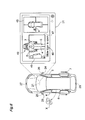
- the passenger car vehicle body 1 includes left and right front wheels 2 and left and right rear wheels 3. At its front portions, the vehicle body 1 includes a left front door 4 and a right front door 5 that can be opened and closed via hinge. At its rear portions, the vehicle body 1 includes a left rear door 6 and a right rear door 7 that can be opened and closed by sliding. The vehicle body 1 further includes, at its rear end, a hatchback type back door 8.
- the left front door 4 and the right front door 5 as well as the left rear door 6 and the right rear door 7 are used for a passenger's getting on/off the vehicle.
- Each one of these doors includes an outside handle 11 on its outer side and an inside handle 12 on the vehicle interior side. With an operation of this outside handle 11 or the inside handle 12, a latch for keeping the door under closed state is released for allowing opening of the door.
- the backdoor 8 at the rear end of the vehicle body 1 is not used for passenger's getting on/off.
- a driver's seat 13 In the interior of the vehicle body 1, there are provided a driver's seat 13, a front passenger's seat 14 and a plurality of rear passenger's seats 15. At a position forwardly of the driver's seat 13, there is provided a steering wheel 16, forwardly of which an instrument panel mounting various meters is disposed. At the foot of the driver's seat 13, there are arranged an accelerator pedal 17 and a brake pedal 18 for operating a brake device BK for the front wheels 2 and the rear wheels 3. And, laterally of the driver's seat 13, there is arranged a shift lever 19 for effecting speed changing operations.
- the right front door 5 is opened when a driver gets on/off the driver's seat 13 and the left front door 4 is opened when a passenger gets on/off the front passenger's seat 14.
- the left rear door 6 and the right rear door 7 are opened respectively when a passenger is to get on/off the rear seat 15.
- a monitor 21 In the vicinity of the drive's seat 13 and at an upper position of the console, there is mounted a monitor 21 forming a touch panel 21T on its displaying face.
- This monitor 21 is of a liquid crystal type having backlight. Needless to say, the monitor 21 can be also a plasma display type or the CRT type.
- the touch panel 21 will be configured as the pressure-sensitive or electrostatic instruction inputting device configured to output a position touched by a finger or the like as location data.
- the monitor 21 includes a speaker 22 also. However, this speaker 22 can be mounted at any other position such as the inner side of a door, etc.
- the left front door 4 mounts a left side view mirror 23 and the right front door 5 mounts a right side view mirror 24.
- the left side view mirror 23 mounts a left side camera 25 and the right side view mirror 24 mounts a right side camera 26.
- a front camera 27 is mounted and at the rear end of the vehicle body 1, a rear camera 28 is mounted.
- the left side camera 25 has its image capturing direction set downwards so as to capture an image of the left side area including the road surface present on the left side of the vehicle body1. And, the captured image of this left side camera 25 includes the left rear door 6.
- the right side camera 26 has its image capturing direction set downwards so as to capture an image of the right side area including the road surface present on the right side of the vehicle body1. And, the captured image of this right side camera 26 includes the right rear door 7.
- These cameras as image capturing devices comprise digital cameras incorporating image pickup devices such as CCD (charge coupled devices) and CIS (CMOS image sensors). Each camera outputs captured information as video information in realtime. Each one of these cameras has a wide angle lens for securing a wide view angle and has its image capturing direction set so as to cause its captured image to include a portion of the vehicle body 1 as well as the road surface in the vicinity of the vehicle body 1.
- the monitor 21 is configured to display navigation information in a navigation mode control and configured to display also parking assistance information in a parking assist mode control. Further, the monitor 21 is configured to display an image for checking a passenger's getting on/off via the left rear door 6 and the right rear door 7 in a passenger's getting on/off checking mode control. Incidentally, in the present invention, there may be provided a separate monitor dedicated to displaying the image in the passenger's getting on/off checking mode control.
- a power steering unit PS for transmitting a rotational operation force of the steering wheel 16 to the front wheels 2 for effecting a powered steering (maneuvering).
- an engine E and a speed changing mechanism T comprising a torque converter, a CVT, etc. for speed-changing the power from this engine E and transmitting the resultant power to the front wheels 2.
- the vehicle body 1 mounts various sensors for detecting a driving operation and moving conditions of the vehicle 1. These sensors will be described more specifically next.
- the operational system of the steering wheel 16 includes a steering sensor S16 for determining a steering operation direction (steering direction) and operation amount (steering amount).
- the operational system for the shift lever 19 includes a shift position sensor S19 for determining a shift position.
- the operational system for the accelerator pedal 17 includes an accelerator sensor S17 for determining an operation amount of the accelerator pedal 17.
- the operational system for the brake pedal 18 includes a brake sensor S18 for detecting presence/absence of an operation.
- a photo-interrupter or pickup type traveling distance sensor S3 for determining a traveling distance of the vehicle 1 based on a rotational amount of the rear wheel 3.
- the traveling distance sensor S3 it is possible to employ a sensor configured to obtain the traveling distance based on the rotational amount of the transmission system incorporated within the speed changing mechanism T. Further, as the traveling distance sensor S3, it is also possible to employ one configured to determine the rotational amount of the front wheel 2. Further, it is also possible to configure such that the traveling amount and the steering amount of the vehicle body 1 are detected based on a captured image of the front camera 27 or the rear camera 28.
- a left door opening detection sensor S6 for detecting an open state of the left rear door 6 and a right door opening detection sensor S7 for detecting an open state of the right rear door 7.
- These left door opening detection sensor S6 and the right door opening detection sensor S7 each is comprised of a limit switch or the like for detecting realization of the open state by outputting a detection signal at the timing of an opening operation of the door is started.
- the left door opening detection sensor S6 and the right door opening detection sensor S7 in the case of an automatic slide door which is opened when the outside handle 11 or the inside handle 12 of these doors is operated or when the driver operates a switch, there may be used sensors for detecting such switch operation.
- an ECU 30 as an image control apparatus constituting the "core" of the parking assistance apparatus of the present invention.
- This ECU 30, as shown in Fig. 3 includes an interface consisting of a sensor input interface 31 and a communication interface 32, and includes also an image output module 33 and a sound/voice output module 34.
- This ECU 30 includes a processing system including a microprocessor, a DSP (digital signal processor), etc. for processing information obtained through the interface and the result of processing is outputted from the image output module 33 to the monitor 21 and outputted also from the sound/voice output module 34 to the speaker 22.
- a processing system including a microprocessor, a DSP (digital signal processor), etc. for processing information obtained through the interface and the result of processing is outputted from the image output module 33 to the monitor 21 and outputted also from the sound/voice output module 34 to the speaker 22.
- This ECU 30 includes a navigation control section 35 for realizing control in the navigation mode, a map data storage section 36 for providing map information to the navigation control section 35, a parking assist control section 37 for realizing control in the parking assist mode and an image processing section 38 for realizing control in the passenger's getting on/off checking mode.
- the navigation control section 35 obtains a self vehicle position represented by longitude information and latitude information from a GPS unit 41 during traveling and then obtains map data corresponding to this self vehicle position and causes the monitor 21 to display the data.
- the navigation control section 35 also causes the monitor 21 to display navigation information for guiding to a desired destination and causes the speaker 22 to output the navigation information in the form of a sound/voice message.
- the map data storage section 36 executes an operation of providing the map data corresponding to the self vehicle position to the navigation control section 35.
- the parking assist control section 37 causes the monitor 21 to display a captured image in at least one of a camera view mode and an around view mode and to display also in a superposed manner the guide information for guiding the vehicle body 1 to a desired parking position, relative to this captured image. Further, as the assist information, assist information of a steering direction or the like is outputted in the form of a sound/voice from the speaker 22. As a steering operation or the like is effected based on such information as above, the vehicle body 1 can be readily guided or introduced to the parking position.
- the image processing section 38 includes a bird's eye view image generating means 38A, a display image generating means 38B, a display target setting means 38C, and an information outputting means 38D.
- the bird's eye view image generating means 38A generates a bird's eye view image to be displayed at a bird's eye view image window 45 in a passenger's getting on/off checking screen shown in Fig. 4 .
- the display image generating means 38B generates a display image to be displayed at a left window 46 or a right window 47 in a passenger's getting on/off checking screen shown in Fig. 4 .
- the display target setting means 38C sets the display image to be displayed at the left window 46 or the right window 47 in the getting on/off checking screen shown in Fig.
- the information outputting means 38D causes the monitor 21 to display the getting on/off checking screen and arranges the bird's eye view image window 45, the left window 46, the right window 47, etc. in a predetermined layout relative to this getting on/off checking screen and displays the images at these respective windows.
- the navigation control section 35, the parking assist control section 37 and the image processing section 38 are comprised of software, but these can alternatively be comprised of hardware or combination of hardware and software, if desired.
- the ECU 30 is comprised of an electronic circuit and various interfaces and/or some or all of the output system can be incorporated in this electronic circuit. Meanwhile, the ECU 30 includes an electronic circuit constituting a processing system or a storage section comprised of memories, registers, etc. as discrete components. The ECU 30 effects input/output of information via data buses, address buses, control buses, or the like.
- the sensor input interface 31 inputs information from the steering sensor S16, the shift position sensor S19, the accelerator sensor S17, the brake sensor S18 and the traveling distance sensor S3.
- the communication interface 32 effects communications via a communication network with the power steering unit PS, the speed changing mechanism T, the brake device BK and a GPS unit 41. Further, this communication interface 32 obtains information from the touch panel 21T, the left side camera 25, the right side camera 26, the front camera 27, the rear camera 28, the left door opening detection sensor S6 and the right door opening detection sensor S7.
- the image output module 33 outputs images to the monitor 21 and the sound/voice output module 34 outputs sounds or voices to the speaker 22.
- This ECU 30 realizes a control in the navigation mode, a control in the parking assist mode and a control in the passenger's getting on/off checking mode.
- a control in the passenger's getting on/off checking mode if at least one of the left rear door 6 and the right rear door 7 is under the open state, an image of the vicinity of the door under the open state is shown with an enlargement thereof on the monitor 21.
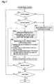
- this control mode will be explained with reference to the flowchart of Fig. 7 .
- the ECU 30 With the ECU 30 in operation, if it is determined, based on a signal from the traveling distance sensor S3 or the shift position sensor S19, that the vehicle 1 is under a stopped state, the ECU 30 obtains signals from the left rear door opening detection sensor S6 and the right door opening detection sensor S7. If it is determined that neither the left rear door 6 nor the right rear door 7 is under an open state, the ECU 30 causes the monitor 21 to display the information under the mode already set (either the navigation mode or the parking assist mode) (steps #101 through #103).
- the mode already set either the navigation mode or the parking assist mode
- the determination at step #101 of "vehicle stopped state” can be a condition of the vehicle speed being 0 km/h in case a vehicle speed sensor is provided or can be a condition of an extremely low speed (1 to 2 km/h), taking into an account some possible delay in the detection by the vehicle speed sensor.
- the control mode is shifted to the passenger's getting on/off checking mode.
- the getting on/off checking mode as shown in Fig. 4 , the getting on/off checking screen is displayed on the monitor 21 and the bird's eye view image window 45 in this getting on/off checking screen displays a bird's eye view image generated by the bird's eye view image generating means 38A (step #104).
- the image displaying areas of the bird's eye view image window 45, the left window 46 and the right window 47 are set in juxtaposition and also a message displaying area 48 and an icon displaying area 49 are arranged in the layout illustrated in Fig. 4 .
- This layout is set by the information outputting means 38D.
- the bird's eye view image generating means 38A converts the captured images of the left side camera 25, the right side camera 26, the front camera 27 and the rear camera 28 into an image viewing the adjacent surrounding of the vehicle body from the above and generates a bird's eye view image through a synthesizing operation of mapping the converted image on a virtual road surface at the center position of the vehicle body in the plane view and then the information outputting means 38D outputs this bird's eye view image to the monitor 21.
- a vehicle body image 45A When this bird's eye view image is displayed at the bird's eye view image window 45, a vehicle body image 45A will be disposed at its center position and a converted image 45B will be mapped around the vehicle body image 45A. And, within this bird's eye view image, there is formed, in the from of a cross, a baseline 45C as the basis for the front/rear position and left/right position relative to the center of the vehicle body 1.
- the bird's eye view image generating means 38A and the information outputting means 38D process the captured images of the plurality of cameras in realtime, it is possible to check a passenger's getting on/off the vehicle body 1 as a video image in the bird's eye view image.
- the left window 46 displays a portion of the captured image of the left side camera 25 with an enlargement thereof.
- the right window 47 displays a portion of the captured image of the right side camera 26 with an enlargement thereof.
- the message displaying area 48 displays a predetermined message comprised of character data.
- the icon displaying area 49 displays an icon corresponding to the rear view of the vehicle body 1. The modes of these displays will be described later herein.
- this control mode when the vehicle body 1 is stopped and at least one of the left rear door 6 and the right rear door 7 reaches its open state, the mode is shifted forcibly to the getting on/off checking mode.
- a selection screen (not shown) may be displayed on the monitor 21, so that the mode may be shifted to the passenger's getting on/off checking mode as the driver puts his/her finger or the like on the button of the getting on/off checking mode in this selection screen.
- the control mode may be configured such that the mode can be shifted to the passenger's getting on/off checking mode in response to a desired operation such as a finger touch on the touch panel 21T, even when the captured image of the rear camera 28 is displayed on the monitor 21.
- the display image generating means 38B processes the captured image of the left side camera 25 or the captured image of the right side camera 26 in realtime. Therefore, the situation of a passenger's getting on/off the vehicle body 1 can be checked in the form of a video image.
- the display target setting means 38C sets the left rear door 6 as the display target.
- the display image generating means 38B separates or "clips" the image of the vicinity of the left rear door 6 from the captured image of the left side camera 25 for its enlargement and generates a right display image through right/left mirror reversal.
- the left display image thus generated will be displayed at the left window 46 by the information outputting means 38D.
- the information outputting means 38D displays a message "Slide door is open" in the message displaying area 48 and displays the left half of the icon in the icon displaying area 49. In the icon thus displayed, the image capturing area will be shown with hatching. In case there has occurred a passenger X' s getting on/off, the passenger X will be shown at the bird's eye view image window 45 and the left window 46.
- the display target setting means 38C sets the right rear door 7 as the display target.
- the display image generating means 38B separates or "clips" the image of the vicinity of the right rear door 7 from the captured image of the right side camera 26 for its enlargement and generates a left display image through right/left mirror reversal. The right display image thus generated will be displayed at the right window 47 by the information outputting means 38D.
- the information outputting means 38D displays a message "Slide door is open” in the message displaying area 48 and displays the right half of the icon in the icon displaying area 49.
- control in the passenger's getting on/off checking mode will be ended. And, except for the case of all controls to be ended, the control will be shifted to the step at #101 and returned to the previously set mode (navigation mode or parking assist mode) and information in this control mode will be displayed on the monitor 21 (step #108).
- the mode will be shifted to the passenger getting on/off checking mode with priority over any other previously effected mode, and the monitor 21 is caused to display the passenger's getting on/off checking screen. And, as the vicinity of the door(s) under the open state is displayed with its enlargement, the driver can check and grasp the situation of the passenger's getting on/off on the monitor 21, without needing to carry out any special operation for its displaying and without needing to view the rear side.
- the present invention may be embodied in any other way than the above as follows.
- (b) There may be provided cameras dedicated to imaging the vicinities of the doors. In this case, the vicinity of a same door can be imaged from different angles by a plurality of cameras. And, if the displaying mode is set so as to display these captured images on the monitor, the checking/grasping of the situation in greater details will be made possible.
- the control mode can be set so as to cause the driver to recognize an open state in the form of a sound/voice when a door is under the open state.
- the sound/voice may be an electronic sound or a human voice (spoken human words).
- the image capturing direction of the side cameras was oriented downwards.
- the invention is not limited thereto.
- the image capturing direction may be oriented rearwards so as to capture an image of the door vicinity.
- the cameras may be disposed so as to eliminate the necessity of separating or clipping a portion of the captured image as was the case with the foregoing embodiment.
- the present invention may be applied to automobiles in general having openable/closable doors.
Landscapes
- Engineering & Computer Science (AREA)
- Multimedia (AREA)
- Mechanical Engineering (AREA)
- Closed-Circuit Television Systems (AREA)
- Fittings On The Vehicle Exterior For Carrying Loads, And Devices For Holding Or Mounting Articles (AREA)
Abstract
Description
- The present invention relates to an image control apparatus, more particularly, to a technique of displaying an image captured by a camera mounted on a vehicle body of e.g. a passenger car on a monitor disposed adjacent a driver's seat.
- As an example of the image control apparatus constructed above,
Patent Document 1 discloses an arrangement wherein each one of left and right doors of the vehicle mounts a camera which captures an image of the rear side and a display is provided in the vehicle interior for displaying the photographic data of the camera when the door is opened. - According to this
Patent Document 1, if the right door is opened, the photographic data of the vehicle rear side captured by the camera mounted on this door is displayed on the right side on the display; whereas if the left door is opened, the photographic data of the vehicle rear side captured by the camera mounted on this door is displayed on the left side on the display. This allows the passenger to recognize, via the display, approaching of an obstacle, thereby to assist a door opening/closing action. - Also,
Patent Document 2 discloses a control configuration wherein based on captured images of a plurality of cameras mounted on a vehicle, a bird's eye view image of the surrounding of the vehicle are displayed as being divided in a plurality of photographic areas on a display unit and when a user has selected one of the photographic areas by touching it on the display unit, the selected photographic area is displayed with an enlargement thereof at a position adjacent the bird's eye view image on the display unit. - According to this
Patent Document 2, even when a pit, an obstacle or the like is present at a location for parking and direct visual recognition of the pit, the obstacle or the like is difficult from the interior of the vehicle, as a camera viewpoint enlarged image or a partially enlarged bird's eye view image is displayed on the display unit, the pit, the obstacle or the like can be readily confirmed on the display unit. -
- Patent Document 1: Japanese Unexamined Patent Application Publication No.
2006-103526 - Patent Document 2: Japanese Unexamined Patent Application Publication No.
2009-239674 - When a passenger car is stopped and a door is opened for allowing a passenger to get on/off the vehicle, the driver seated at the driver's seat may sometimes desire to check the situation of the passenger's getting on/off or an obstacle or the like which may be present around the vehicle. In particular, when a child is to get on/off the vehicle with the vehicle being stopped at the shoulder of a road, other vehicles can run on the side of the road, so reliable checking of the getting on/off may be desirable from the safety point of view also.
- To cope with the above-described current situation, according to the technique disclosed in
Patent Document 1, the technique is configured to allow visual checking, via the display unit disposed adjacent the driver's seat, the condition of an automobile, a motor cycle or the like approaching from the rear side of the vehicle when the door is opened. However, as the technique does not take into account checking of a passenger's getting on/off, the technique suffers the difficulty of checking of a passenger's getting on/off. - Further, in the case of the technique disclosed in cited
Document 2, the technique allows displaying of the door vicinity with enlargement thereof. However, when a passenger's getting on/off is to be checked, it is necessary for the driver to identify the door used for the passenger's getting on/off and to specify the area where that door is to be photographed, thus the technique being troublesome. - The object of the present invention is to reasonably configure an image control apparatus that allows a driver to easily check the situation of a passenger's getting on/off a vehicle.
- According to the characterizing feature of the present invention, there are provided a camera which captures an image of the vicinity of the vehicle door, a monitor capable of displaying the image captured by the camera and a door opening detection sensor which detects an open state of the vehicle door, wherein the monitor displays the image captured by the camera when the door opening detection sensor detects an open state of the door.
- With the above-described arrangement, when the door opening detection sensor has detected an open state of the door, the monitor displays the image captured by the camera. That is, upon establishment of open state of the door, the driver can check the image of the vicinity of the door which is under the open state, with the driver remaining at the position of the driver's seat and without the driver's needing to carry out any special operation.
As a result, there has been realized an image control apparatus that allows a driver to easily check the situation of a passenger's getting on/off a vehicle. - The present invention may be alternatively configured as follows. Namely, as the camera, there are provided a left side camera which captures an image of the left side area including the left side road surface of the vehicle body and a right side camera which captures an image of the right side area including the right side road surface of the vehicle body;
as the door opening detection sensor, there are provided a left door opening detection sensor which detects an open state of the left door of the vehicle body and a right door opening detection sensor which detects an open state of the right door of the vehicle body;
there is provided a display image generating means which generates an image of the left door vicinity as a left display image from the captured image of the left side camera and an image of the right door vicinity as a right display image from the captured image of the right side camera,; and
there is provided an information outputting means which causes said monitor to display one of the left display image and the right display image corresponding to detection in a predetermined layout when at least one of the left door opening detection sensor and the right door opening detection sensor has detected an open state. - According to the above arrangement, when at least one of the left door opening detection sensor and the right door opening detection sensor has detected an open state, the information outputting means causes the monitor to display one of the left display image and the right display image corresponding to this detection in a predetermined layout. As the image is displayed in such predetermined layout, the identification of the door under the open state can be easily made, based on the display position of the image.
- In the present invention, said display image generating means may be configured to display said left display image through an operation of effecting mirror reversal of right/left on at least a portion of said left side camera captured image and to display said right display image through an operation of effecting mirror reversal of right/left on at least a portion of said right side camera captured image.
- With the above-described arrangement, the monitor will display the left display image which has been generated through an operation of effecting mirror reversal of right/left on at least a portion of the left side camera captured image and the right display image which has been generated through an operation of effecting mirror reversal of right/left on at least a portion of the right side camera captured image. Hence, it is possible to grasp the situation of the door vicinity via the monitor with a feel similar to the feel of visually checking from the driver's seat via the rearview mirror.
- According to a preferred embodiment of the present invention,
there is provided a bird's eye view image generating means which generates a bird's eye view image viewing the vehicle surrounding from the above, based on the image captured by the left side camera and the image captured by the right side camera; and
said information outputting means causes said monitor to display at least one of the left display image and the right display mage as well as said bird's eye view image in a predetermined layout. - With the above-described arrangement, the bird's eye view image generating means generates a bird's eye view image viewing the vehicle surrounding form the above, based on the photographic image captured by the left side camera and the photographic image captured by the right side camera. Further, when at least one of the left door opening detection sensor and the right door opening detection sensor has detected an open state, the information outputting means causes the monitor to display at least one of the left display image and the right display image in a predetermined layout and to display also a bird's eye view image, so that it becomes possible to grasp not only the situation of the door vicinity, but also the situation of the vehicle vicinity in general.
- Preferably, in the present invention, for said monitor, said information outputting means sets a bird's eye view image window which displays said bird's eye view image and sets also a left window which displays said left display image and a right window which displays said right display image in left/right juxtaposed positional relationship with each other.
- With the above-described arrangement, when e.g. both the left and right doors are opened, the information outputting means causes the left photographic image to be displayed at the left window and causes the right photographic image to be displayed at the right window. With this, from the left widow and the right window juxtaposed, the driver can grasp the situation of the door vicinity without unnatural feel about the positional relationship.
- According to the present invention, preferably, as said camera, there is provided a left side camera which captures an image of the left side area including the left side road surface of the vehicle body,
as said door opening sensor, there is provided a left door opening detection sensor which detects an open state of the left door of the vehicle body; and
there is provided a display image generating means which generates an image of the left door vicinity as a left display image from the captured image of the left side camera through an operation of effecting mirror reversal of right/left on at least a portion of said left side camera captured image. - With the above-described arrangement, when the left door opening detection sensor detects an open state of the left door of the vehicle body, the information outputting means causes the monitor to display the left display image. With this displaying of the image, based on the displaying position of the image, the image of the vicinity of the left door under the open state can be checked
- According to the present invention, preferably, as said camera, there is provided a right side camera which captures an image of the right side area including the right side road surface of the vehicle body,
as said door opening sensor, there is provided a right door opening detection sensor which detects an open state of the right door of the vehicle body; and
there is provided a display image generating means which generates an image of the right door vicinity as a right display image from the captured image of the right side camera through an operation of effecting mirror reversal of right/left on at least a portion of said right side camera captured image. - With the above-described arrangement, when the right door opening detection sensor detects an open state of the right door of the vehicle body, the information outputting means causes the monitor to display the right display image. With this displaying of the image, based on the displaying position of the image, the image of the vicinity of the right door under the open state can be checked.
- According to the present invention, preferably, there is provided a control mode setting section which executes, as getting on/off checking mode, a control operation wherein when it is detected that the vehicle is stopped and the door opening detection sensor has detected an open state of a door, the captured image of the camera is displayed on the monitor with priority over the displaying of information of a currently executed control mode.
- With the above arrangement, even when a certain control mode is being executed and information according to this control mode is being displayed on the monitor, if the vehicle is stopped and a door is opened, the control mode setting section executes the getting on/off checking mode with priority, so that the situation of the door being opened can be checked on the monitor.
-
- [
Fig. 1 ] is a plane view schematically showing a construction of a passenger car. - [
Fig. 2 ] is a partially cutaway perspective view of the passenger car. - [
Fig. 3 ] is a circuit block diagram of a control system. - [
Fig. 4 ] is a diagram showing the layout of a getting on/off checking screen. - [
Fig. 5 ] is a diagram showing the getting on/off checking screen when the right rear door is opened. - [
Fig. 6 ] is a diagram showing the getting on/off checking screen when the left rear door and the right rear door are opened. - [
Fig. 7 ] is a flowchart of a monitor display control. - Next, an embodiment of the present invention will be described with reference to the accompanying drawings.
- According to the present embodiment, there is provided an image control apparatus configured for generating a bird's eye view image showing the vicinity of a
vehicle body 1 as seen from above, from captured images of a plurality of cameras mounted on thevehicle body 1 and causing amonitor 21 to display this bird's eye view image. In particular, this image control apparatus is configured to execute a control mode wherein when any door is opened, a captured image of a camera of the plurality of cameras that includes this door in its image capturing area is displayed on themonitor 21 for allowing a passenger's getting on/off the vehicle. Next, this control mode and its control configuration will be explained. - As shown in
Fig. 1 andFig. 2 , the passengercar vehicle body 1 includes left and rightfront wheels 2 and left and rightrear wheels 3. At its front portions, thevehicle body 1 includes a leftfront door 4 and a rightfront door 5 that can be opened and closed via hinge. At its rear portions, thevehicle body 1 includes a leftrear door 6 and a rightrear door 7 that can be opened and closed by sliding. Thevehicle body 1 further includes, at its rear end, a hatchback typeback door 8. - The left
front door 4 and the rightfront door 5 as well as the leftrear door 6 and the rightrear door 7 are used for a passenger's getting on/off the vehicle. Each one of these doors includes anoutside handle 11 on its outer side and aninside handle 12 on the vehicle interior side. With an operation of thisoutside handle 11 or theinside handle 12, a latch for keeping the door under closed state is released for allowing opening of the door. Incidentally, thebackdoor 8 at the rear end of thevehicle body 1 is not used for passenger's getting on/off. - In the interior of the
vehicle body 1, there are provided a driver'sseat 13, a front passenger'sseat 14 and a plurality of rear passenger'sseats 15. At a position forwardly of the driver'sseat 13, there is provided asteering wheel 16, forwardly of which an instrument panel mounting various meters is disposed. At the foot of the driver'sseat 13, there are arranged anaccelerator pedal 17 and abrake pedal 18 for operating a brake device BK for thefront wheels 2 and therear wheels 3. And, laterally of the driver'sseat 13, there is arranged ashift lever 19 for effecting speed changing operations. - Needless to say, the right
front door 5 is opened when a driver gets on/off the driver'sseat 13 and the leftfront door 4 is opened when a passenger gets on/off the front passenger'sseat 14. The leftrear door 6 and the rightrear door 7 are opened respectively when a passenger is to get on/off therear seat 15. - In the vicinity of the drive's
seat 13 and at an upper position of the console, there is mounted amonitor 21 forming atouch panel 21T on its displaying face. Thismonitor 21 is of a liquid crystal type having backlight. Needless to say, themonitor 21 can be also a plasma display type or the CRT type. Thetouch panel 21 will be configured as the pressure-sensitive or electrostatic instruction inputting device configured to output a position touched by a finger or the like as location data. Themonitor 21 includes aspeaker 22 also. However, thisspeaker 22 can be mounted at any other position such as the inner side of a door, etc. - The left
front door 4 mounts a leftside view mirror 23 and the rightfront door 5 mounts a rightside view mirror 24. In the instant embodiment, as image capturing devices for capturing images of the surrounding of the vehicle body, the leftside view mirror 23 mounts aleft side camera 25 and the rightside view mirror 24 mounts aright side camera 26. And, at the front end of thevehicle body 1, afront camera 27 is mounted and at the rear end of thevehicle body 1, arear camera 28 is mounted. - In particular, the
left side camera 25 has its image capturing direction set downwards so as to capture an image of the left side area including the road surface present on the left side of the vehicle body1. And, the captured image of thisleft side camera 25 includes the leftrear door 6. Similarly, theright side camera 26 has its image capturing direction set downwards so as to capture an image of the right side area including the road surface present on the right side of the vehicle body1. And, the captured image of thisright side camera 26 includes the rightrear door 7. - These cameras as image capturing devices comprise digital cameras incorporating image pickup devices such as CCD (charge coupled devices) and CIS (CMOS image sensors). Each camera outputs captured information as video information in realtime. Each one of these cameras has a wide angle lens for securing a wide view angle and has its image capturing direction set so as to cause its captured image to include a portion of the
vehicle body 1 as well as the road surface in the vicinity of thevehicle body 1. - The
monitor 21 is configured to display navigation information in a navigation mode control and configured to display also parking assistance information in a parking assist mode control. Further, themonitor 21 is configured to display an image for checking a passenger's getting on/off via the leftrear door 6 and the rightrear door 7 in a passenger's getting on/off checking mode control. Incidentally, in the present invention, there may be provided a separate monitor dedicated to displaying the image in the passenger's getting on/off checking mode control. - At a front portion of the vehicle body, there is mounted a power steering unit PS for transmitting a rotational operation force of the
steering wheel 16 to thefront wheels 2 for effecting a powered steering (maneuvering). Also, at the front portion of the vehicle body, there are mounted an engine E and a speed changing mechanism T comprising a torque converter, a CVT, etc. for speed-changing the power from this engine E and transmitting the resultant power to thefront wheels 2. - The
vehicle body 1 mounts various sensors for detecting a driving operation and moving conditions of thevehicle 1. These sensors will be described more specifically next. The operational system of thesteering wheel 16 includes a steering sensor S16 for determining a steering operation direction (steering direction) and operation amount (steering amount). The operational system for theshift lever 19 includes a shift position sensor S19 for determining a shift position. Also, the operational system for theaccelerator pedal 17 includes an accelerator sensor S17 for determining an operation amount of theaccelerator pedal 17. The operational system for thebrake pedal 18 includes a brake sensor S18 for detecting presence/absence of an operation. - Adjacent each
rear wheel 3, there is provided a photo-interrupter or pickup type traveling distance sensor S3 for determining a traveling distance of thevehicle 1 based on a rotational amount of therear wheel 3. Incidentally, as the traveling distance sensor S3, it is possible to employ a sensor configured to obtain the traveling distance based on the rotational amount of the transmission system incorporated within the speed changing mechanism T. Further, as the traveling distance sensor S3, it is also possible to employ one configured to determine the rotational amount of thefront wheel 2. Further, it is also possible to configure such that the traveling amount and the steering amount of thevehicle body 1 are detected based on a captured image of thefront camera 27 or therear camera 28. - There are also provided a left door opening detection sensor S6 for detecting an open state of the left
rear door 6 and a right door opening detection sensor S7 for detecting an open state of the rightrear door 7. These left door opening detection sensor S6 and the right door opening detection sensor S7 each is comprised of a limit switch or the like for detecting realization of the open state by outputting a detection signal at the timing of an opening operation of the door is started. Meanwhile, as the left door opening detection sensor S6 and the right door opening detection sensor S7, in the case of an automatic slide door which is opened when theoutside handle 11 or theinside handle 12 of these doors is operated or when the driver operates a switch, there may be used sensors for detecting such switch operation. - At the center of the vehicle body, there is mounted an
ECU 30 as an image control apparatus constituting the "core" of the parking assistance apparatus of the present invention. ThisECU 30, as shown inFig. 3 , includes an interface consisting of asensor input interface 31 and acommunication interface 32, and includes also animage output module 33 and a sound/voice output module 34. - This
ECU 30 includes a processing system including a microprocessor, a DSP (digital signal processor), etc. for processing information obtained through the interface and the result of processing is outputted from theimage output module 33 to themonitor 21 and outputted also from the sound/voice output module 34 to thespeaker 22. - This
ECU 30 includes anavigation control section 35 for realizing control in the navigation mode, a mapdata storage section 36 for providing map information to thenavigation control section 35, a parkingassist control section 37 for realizing control in the parking assist mode and animage processing section 38 for realizing control in the passenger's getting on/off checking mode. - The
navigation control section 35 obtains a self vehicle position represented by longitude information and latitude information from aGPS unit 41 during traveling and then obtains map data corresponding to this self vehicle position and causes themonitor 21 to display the data. Thenavigation control section 35 also causes themonitor 21 to display navigation information for guiding to a desired destination and causes thespeaker 22 to output the navigation information in the form of a sound/voice message. The mapdata storage section 36 executes an operation of providing the map data corresponding to the self vehicle position to thenavigation control section 35. - The parking
assist control section 37 causes themonitor 21 to display a captured image in at least one of a camera view mode and an around view mode and to display also in a superposed manner the guide information for guiding thevehicle body 1 to a desired parking position, relative to this captured image. Further, as the assist information, assist information of a steering direction or the like is outputted in the form of a sound/voice from thespeaker 22. As a steering operation or the like is effected based on such information as above, thevehicle body 1 can be readily guided or introduced to the parking position. - The
image processing section 38 includes a bird's eye view image generating means 38A, a display image generating means 38B, a display target setting means 38C, and an information outputting means 38D. The bird's eye view image generating means 38A generates a bird's eye view image to be displayed at a bird's eyeview image window 45 in a passenger's getting on/off checking screen shown inFig. 4 . The display image generating means 38B generates a display image to be displayed at aleft window 46 or aright window 47 in a passenger's getting on/off checking screen shown inFig. 4 . The display target setting means 38C sets the display image to be displayed at theleft window 46 or theright window 47 in the getting on/off checking screen shown inFig. 4 . The information outputting means 38D causes themonitor 21 to display the getting on/off checking screen and arranges the bird's eyeview image window 45, theleft window 46, theright window 47, etc. in a predetermined layout relative to this getting on/off checking screen and displays the images at these respective windows. - Incidentally, the
navigation control section 35, the parking assistcontrol section 37 and theimage processing section 38 are comprised of software, but these can alternatively be comprised of hardware or combination of hardware and software, if desired. - The
ECU 30 is comprised of an electronic circuit and various interfaces and/or some or all of the output system can be incorporated in this electronic circuit. Meanwhile, theECU 30 includes an electronic circuit constituting a processing system or a storage section comprised of memories, registers, etc. as discrete components. TheECU 30 effects input/output of information via data buses, address buses, control buses, or the like. - The
sensor input interface 31 inputs information from the steering sensor S16, the shift position sensor S19, the accelerator sensor S17, the brake sensor S18 and the traveling distance sensor S3. - The
communication interface 32 effects communications via a communication network with the power steering unit PS, the speed changing mechanism T, the brake device BK and aGPS unit 41. Further, thiscommunication interface 32 obtains information from thetouch panel 21T, theleft side camera 25, theright side camera 26, thefront camera 27, therear camera 28, the left door opening detection sensor S6 and the right door opening detection sensor S7. - The
image output module 33 outputs images to themonitor 21 and the sound/voice output module 34 outputs sounds or voices to thespeaker 22. - This
ECU 30 realizes a control in the navigation mode, a control in the parking assist mode and a control in the passenger's getting on/off checking mode. In particular, in the control in the passenger's getting on/off checking mode, if at least one of the leftrear door 6 and the rightrear door 7 is under the open state, an image of the vicinity of the door under the open state is shown with an enlargement thereof on themonitor 21. Next, this control mode will be explained with reference to the flowchart ofFig. 7 . - With the
ECU 30 in operation, if it is determined, based on a signal from the traveling distance sensor S3 or the shift position sensor S19, that thevehicle 1 is under a stopped state, theECU 30 obtains signals from the left rear door opening detection sensor S6 and the right door opening detection sensor S7. If it is determined that neither the leftrear door 6 nor the rightrear door 7 is under an open state, theECU 30 causes themonitor 21 to display the information under the mode already set (either the navigation mode or the parking assist mode) (steps #101 through #103).
Incidentally, the determination atstep # 101 of "vehicle stopped state" can be a condition of the vehicle speed being 0 km/h in case a vehicle speed sensor is provided or can be a condition of an extremely low speed (1 to 2 km/h), taking into an account some possible delay in the detection by the vehicle speed sensor. - Conversely, if it is determined, based on the signals from the left door opening detection sensor S6 and the right door opening detection sensor S7, that at least one of the left
rear door 6 and the rightrear door 7 is now under an open state, the control mode is shifted to the passenger's getting on/off checking mode. In this getting on/off checking mode, as shown inFig. 4 , the getting on/off checking screen is displayed on themonitor 21 and the bird's eyeview image window 45 in this getting on/off checking screen displays a bird's eye view image generated by the bird's eye view image generating means 38A (step #104). - In this getting on/off checking screen, the image displaying areas of the bird's eye
view image window 45, theleft window 46 and theright window 47 are set in juxtaposition and also amessage displaying area 48 and anicon displaying area 49 are arranged in the layout illustrated inFig. 4 . This layout is set by the information outputting means 38D. - The bird's eye view image generating means 38A converts the captured images of the
left side camera 25, theright side camera 26, thefront camera 27 and therear camera 28 into an image viewing the adjacent surrounding of the vehicle body from the above and generates a bird's eye view image through a synthesizing operation of mapping the converted image on a virtual road surface at the center position of the vehicle body in the plane view and then the information outputting means 38D outputs this bird's eye view image to themonitor 21. - When this bird's eye view image is displayed at the bird's eye
view image window 45, avehicle body image 45A will be disposed at its center position and a convertedimage 45B will be mapped around thevehicle body image 45A. And, within this bird's eye view image, there is formed, in the from of a cross, abaseline 45C as the basis for the front/rear position and left/right position relative to the center of thevehicle body 1. In particular, as the bird's eye view image generating means 38A and the information outputting means 38D process the captured images of the plurality of cameras in realtime, it is possible to check a passenger's getting on/off thevehicle body 1 as a video image in the bird's eye view image. - The
left window 46 displays a portion of the captured image of theleft side camera 25 with an enlargement thereof. Theright window 47 displays a portion of the captured image of theright side camera 26 with an enlargement thereof. Themessage displaying area 48 displays a predetermined message comprised of character data. Theicon displaying area 49 displays an icon corresponding to the rear view of thevehicle body 1. The modes of these displays will be described later herein. - In this control mode, when the
vehicle body 1 is stopped and at least one of the leftrear door 6 and the rightrear door 7 reaches its open state, the mode is shifted forcibly to the getting on/off checking mode. Alternatively, however, a selection screen (not shown) may be displayed on themonitor 21, so that the mode may be shifted to the passenger's getting on/off checking mode as the driver puts his/her finger or the like on the button of the getting on/off checking mode in this selection screen. - Especially, according to one alternative mode of control conceivable, even under a vehicle stopped state, if the shift position sensor S19 detects that the
shift lever 19 is set to the reverse position. themonitor 21 may be caused to display the captured image of the rear camera 28 (reverse monitor display) with priority over any other control mode. In the present invention, the control mode may be configured such that the mode can be shifted to the passenger's getting on/off checking mode in response to a desired operation such as a finger touch on thetouch panel 21T, even when the captured image of therear camera 28 is displayed on themonitor 21. - Next, if it is determined that at least one of the left
rear door 6 and the rightrear door 7 is under the open state, an image captured from the vicinity of the door under the open state will be displayed at theleft window 46 or theright window 47 or at both theleft window 46 and theright window 47. In association with this displaying, a message in the form of character data is displayed in themessage displaying area 48 and an icon corresponding to the rear view of thevehicle body 1 is displayed in the ion displaying area 49 (steps #105 and #106). - In this way, when an image is to be displayed at the
left window 46 or theright window 47, the display image generating means 38B processes the captured image of theleft side camera 25 or the captured image of theright side camera 26 in realtime. Therefore, the situation of a passenger's getting on/off thevehicle body 1 can be checked in the form of a video image. - As an example (1), in case the left door opening detection sensor S6 detects the left
rear door 6 being under the open state, the display target setting means 38C sets the leftrear door 6 as the display target. Next, the display image generating means 38B separates or "clips" the image of the vicinity of the leftrear door 6 from the captured image of theleft side camera 25 for its enlargement and generates a right display image through right/left mirror reversal. The left display image thus generated will be displayed at theleft window 46 by the information outputting means 38D. - Further, the information outputting means 38D displays a message "Slide door is open" in the
message displaying area 48 and displays the left half of the icon in theicon displaying area 49. In the icon thus displayed, the image capturing area will be shown with hatching. In case there has occurred a passenger X' s getting on/off, the passenger X will be shown at the bird's eyeview image window 45 and theleft window 46. - As an example (2), as shown in
Fig. 5 , in case the right door opening detection sensor S7 detects the rightrear door 7 being under the open state, the display target setting means 38C sets the rightrear door 7 as the display target. Next, the display image generating means 38B separates or "clips" the image of the vicinity of the rightrear door 7 from the captured image of theright side camera 26 for its enlargement and generates a left display image through right/left mirror reversal. The right display image thus generated will be displayed at theright window 47 by the information outputting means 38D. - Further, the information outputting means 38D displays a message "Slide door is open" in the
message displaying area 48 and displays the right half of the icon in theicon displaying area 49. - As an example (3), as shown in
Fig. 6 , in case both the leftrear door 6 and the rightrear door 7 are under the open state at a time, an operation similar to the above will be effected, so that the left display image will be displayed at theleft window 46 and the right display image will be displayed at theright window 47. And, themessage displaying area 48 will display a message "Slide doors are open" and theicon displaying area 49 will display the whole icon. - Thereafter, in case the left
rear door 6 and the rightrear door 7 are closed respectively, the control in the passenger's getting on/off checking mode will be ended. And, except for the case of all controls to be ended, the control will be shifted to the step at #101 and returned to the previously set mode (navigation mode or parking assist mode) and information in this control mode will be displayed on the monitor 21 (step #108). - As described above, according to the present invention, in case the left
rear door 6 and/or the rightrear door 7 is/are under the open state, the mode will be shifted to the passenger getting on/off checking mode with priority over any other previously effected mode, and themonitor 21 is caused to display the passenger's getting on/off checking screen. And, as the vicinity of the door(s) under the open state is displayed with its enlargement, the driver can check and grasp the situation of the passenger's getting on/off on themonitor 21, without needing to carry out any special operation for its displaying and without needing to view the rear side. - Further, as an enlarged image of the vicinity of the left
rear door 6 is displayed at theleft window 46 and an enlarged image of the vicinity of the rightrear door 7 is displayed at theright window 47 and these left andright windows left window 46 and theright window 47 are left/right mirror reversed images, the checking operation can be done with a feeling similar to checking with a rear view mirror, without any unnaturalness in the feeling. - Especially, since the images of the camera which are provided originally in the side mirrors for the purpose of generation of a bird's eye view image, there is no need for separately providing any cameras solely for imaging the door vicinities. Hence, there will not be invited any cost increase due to provision of such cameras.
- The present invention may be embodied in any other way than the above as follows.
- (a) In case the
outside handle 11 or theinside handle 12 is operated, an image of the vicinity of the operated door may be displayed on the monitor even before the door reaches its open state. In this case, it is possible to start the displaying at the timing of the operation of theoutside handle 11 or theinside handle 12, whereby checking at an earlier timing is realized. - (b) There may be provided cameras dedicated to imaging the vicinities of the doors. In this case, the vicinity of a same door can be imaged from different angles by a plurality of cameras. And, if the displaying mode is set so as to display these captured images on the monitor, the checking/grasping of the situation in greater details will be made possible.
- (c) The control mode can be set so as to cause the driver to recognize an open state in the form of a sound/voice when a door is under the open state. With this arrangement, even when the driver's line of vision is not toward the
monitor 21, it is possible to cause the driver to direct his/her line of vision toward themonitor 21 so as to check getting on/off of a passenger through the passenger's getting on/off checking screen. Incidentally, the sound/voice may be an electronic sound or a human voice (spoken human words). - (d) In the instant embodiment, the image capturing direction of the side cameras was oriented downwards. However, the invention is not limited thereto. For instance, the image capturing direction may be oriented rearwards so as to capture an image of the door vicinity. In this case, the cameras may be disposed so as to eliminate the necessity of separating or clipping a portion of the captured image as was the case with the foregoing embodiment.
- The present invention may be applied to automobiles in general having openable/closable doors.
-
- 1
- vehicle body
- 6
- door (left rear door)
- 7
- door (right rear door)
- 21
- monitor
- 25
- camera: left side camera
- 26
- camera: right side camera
- 38A
- bird's eye view image generating means
- 38B
- display image generating means
- 38D
- information outputting means
- 39
- control mode setting section
- 45
- bird's eye view image window
- 46
- left window
- 47
- right window
- S6
- door opening detection sensor: left door opening detection sensor
- S7
- door opening detection sensor: right door opening detection sensor
Claims (8)
- An image control apparatus comprising:a camera which captures an image of the vicinity of the vehicle door;a monitor capable of displaying the image captured by the camera; anda door opening detection sensor which detects an open state of the vehicle door;wherein the monitor displays the image captured by the camera when the door opening detection sensor detects an open state of the door.
- An image control apparatus according to claim 1, wherein:
as the camera, there are provided a left side camera which captures an image of the left side area including the left side road surface of the vehicle body and a right side camera which captures an image of the right side area including the right side road surface of the vehicle body;
as the door opening detection sensor, there are provided a left door opening detection sensor which detects an open state of the left door of the vehicle body and a right door opening detection sensor which detects an open state of the right door of the vehicle body;
there is provided a display image generating means which generates an image of the left door vicinity as a left display image from the captured image of the left side camera and an image of the right door vicinity as a right display image from the captured image of the right side camera,; and
there is provided an information outputting means which causes said monitor to display one of the left display image and the right display image corresponding to detection in a predetermined layout when at least one of the left door opening detection sensor and the right door opening detection sensor has detected an open state. - An image control apparatus according to claim 2, wherein;
said display image generating means is configured to display said left display image through an operation of effecting mirror reversal of right/left on at least a portion of said left side camera captured image and to display said right display image through an operation of effecting mirror reversal of right/left on at least a portion of said right side camera captured image. - An image control apparatus according to claim 2 or 3, wherein;
there is provided a bird's eye view image generating means which generates a bird's eye view image viewing the vehicle surrounding from the above, based on the image captured by the left side camera and the image captured by the right side camera; and
said information outputting means causes said monitor to display at least one of the left display image and the right display mage as well as said bird's eye view image in a predetermined layout. - An image control apparatus according to claim 4, wherein;
for said monitor, said information outputting means sets a bird's eye view image window which displays said bird's eye view image and sets also a left window which displays said left display image and a right window which displays said right display image in left/right juxtaposed positional relationship with each other. - An image control apparatus according to claim 1, wherein;
as said camera, there is provided a left side camera which captures an image of the left side area including the left side road surface of the vehicle body,
as said door opening sensor, there is provided a left door opening detection sensor which detects an open state of the left door of the vehicle body; and
there is provided a display image generating means which generates an image of the left door vicinity as a left display image from the captured image of the left side camera through an operation of effecting mirror reversal of right/left on at least a portion of said left side camera captured image. - An image control apparatus according to claim 1, wherein;
as said camera, there is provided a right side camera which captures an image of the right side area including the right side road surface of the vehicle body,
as said door opening sensor, there is provided a right door opening detection sensor which detects an open state of the right door of the vehicle body; and
there is provided a display image generating means which generates an image of the right door vicinity as a right display image from the captured image of the right side camera through an operation of effecting mirror reversal of right/left on at least a portion of said right side camera captured image. - An image control apparatus according to any one of claims 1-7, wherein;
there is provided a control mode setting section which executes, as getting on/off checking mode, a control operation wherein when it is detected that the vehicle is stopped and the door opening detection sensor has detected an open state of a door, the captured image of the camera is displayed on the monitor with priority over the displaying of information of a currently executed control mode.
Applications Claiming Priority (2)
| Application Number | Priority Date | Filing Date | Title |
|---|---|---|---|
| JP2010056355A JP5397697B2 (en) | 2010-03-12 | 2010-03-12 | Image control device |
| PCT/JP2011/052259 WO2011111448A1 (en) | 2010-03-12 | 2011-02-03 | Image control apparatus |
Publications (3)
| Publication Number | Publication Date |
|---|---|
| EP2547104A1 true EP2547104A1 (en) | 2013-01-16 |
| EP2547104A4 EP2547104A4 (en) | 2013-08-07 |
| EP2547104B1 EP2547104B1 (en) | 2015-06-10 |
Family
ID=44563274
Family Applications (1)
| Application Number | Title | Priority Date | Filing Date |
|---|---|---|---|
| EP11753110.3A Not-in-force EP2547104B1 (en) | 2010-03-12 | 2011-02-03 | Image control apparatus |
Country Status (5)
| Country | Link |
|---|---|
| US (1) | US20130002877A1 (en) |
| EP (1) | EP2547104B1 (en) |
| JP (1) | JP5397697B2 (en) |
| CN (1) | CN102783145B (en) |
| WO (1) | WO2011111448A1 (en) |
Cited By (4)
| Publication number | Priority date | Publication date | Assignee | Title |
|---|---|---|---|---|
| EP3487173A4 (en) * | 2016-12-28 | 2019-07-31 | JVC Kenwood Corporation | IMAGE GENERATING DEVICE, IMAGE GENERATING SYSTEM, AND IMAGE GENERATING METHOD, AND PROGRAM |
| EP3663161A4 (en) * | 2017-07-31 | 2021-06-23 | Hitachi Kokusai Electric Inc. | VIDEO DISPLAY SYSTEM AND VIDEO DISPLAY METHOD |
| EP3848247A4 (en) * | 2018-09-07 | 2021-07-14 | Denso Corporation | DISPLAY CONTROL DEVICE FOR ELECTRONIC MIRROR AND ELECTRONIC MIRROR SYSTEM INCLUDING IT |
| FR3120030A1 (en) * | 2021-02-25 | 2022-08-26 | Psa Automobiles Sa | Method and digital rear-view device used by a vehicle to replace exterior mirrors of the vehicle |
Families Citing this family (33)
| Publication number | Priority date | Publication date | Assignee | Title |
|---|---|---|---|---|
| KR100959347B1 (en) * | 2010-02-24 | 2010-05-20 | 조성호 | An apparatus furnishing left-right-rear side view of vehicles |
| EP2583868B1 (en) * | 2010-06-15 | 2018-06-20 | Aisin Seiki Kabushiki Kaisha | Drive assist device |
| EP2631374B1 (en) * | 2010-10-22 | 2020-09-30 | Hitachi Construction Machinery Co., Ltd. | Work machine peripheral monitoring device |
| JP5750344B2 (en) * | 2011-09-16 | 2015-07-22 | 日立建機株式会社 | Ambient monitoring device for work equipment |
| CN103975315B (en) * | 2011-12-06 | 2017-04-12 | 英特尔公司 | Method and system for improving responsiveness in a vehicle computing platform |
| KR101362326B1 (en) * | 2012-08-06 | 2014-02-24 | 현대모비스 주식회사 | Rear camera system for vehicle having parking alignment function and parking guide system using the same |
| DE102013000273A1 (en) * | 2013-01-09 | 2014-07-31 | Daimler Ag | Apparatus and method for displaying information on a display device in a vehicle |
| CN104228714A (en) * | 2013-06-14 | 2014-12-24 | 华创车电技术中心股份有限公司 | Method for providing parking image |
| GB2515099B (en) * | 2013-06-14 | 2015-11-11 | Jaguar Land Rover Ltd | Door protection system |
| KR101482171B1 (en) * | 2013-09-05 | 2015-01-13 | 현대모비스(주) | Control method for around view stop mode |
| CN104063991B (en) * | 2014-06-28 | 2017-06-30 | 宁波吉利汽车研究开发有限公司 | One kind is got off safety reminding device and its detection method |
| US20160159281A1 (en) * | 2014-12-04 | 2016-06-09 | Hyundai Mobis Co., Ltd. | Vehicle and control method thereof |
| US10486599B2 (en) * | 2015-07-17 | 2019-11-26 | Magna Mirrors Of America, Inc. | Rearview vision system for vehicle |
| JP6545108B2 (en) * | 2016-01-14 | 2019-07-17 | アルパイン株式会社 | Parking assistance apparatus and parking assistance method |
| JP6675206B2 (en) * | 2016-01-19 | 2020-04-01 | 株式会社モリタホールディングス | Monitoring and display device for vehicles |
| CN107089190A (en) * | 2016-02-18 | 2017-08-25 | 奥迪股份公司 | For warning system, method for warming and the corresponding vehicle for aiding in user to get off |
| US20170297487A1 (en) * | 2016-04-14 | 2017-10-19 | GM Global Technology Operations LLC | Vehicle door opening assessments |
| KR101846666B1 (en) * | 2016-05-02 | 2018-04-06 | 현대자동차주식회사 | Apparatus for controlling the side/back watching apparatus installed inside of vehicle and method for the same |
| JP2017210063A (en) * | 2016-05-24 | 2017-11-30 | 株式会社東海理化電機製作所 | Vehicle display device |
| JP6794193B2 (en) * | 2016-09-02 | 2020-12-02 | 株式会社小松製作所 | Image display system for work machines |
| JP2018043643A (en) * | 2016-09-14 | 2018-03-22 | 株式会社東海理化電機製作所 | Vehicular visual confirmation device |
| JP6730614B2 (en) * | 2017-02-28 | 2020-07-29 | 株式会社Jvcケンウッド | Vehicle display control device, vehicle display system, vehicle display control method and program |
| JP6769383B2 (en) * | 2017-04-13 | 2020-10-14 | トヨタ自動車株式会社 | Automatic driving device and notification method |
| CN109455140B (en) * | 2017-09-06 | 2022-03-01 | 丰田自动车株式会社 | image display device |
| JP6875551B2 (en) * | 2017-12-14 | 2021-05-26 | 本田技研工業株式会社 | Vehicle monitor layout structure |
| JP6967729B2 (en) * | 2018-03-30 | 2021-11-17 | パナソニックIpマネジメント株式会社 | Driving support system, information processing device and information processing method |
| DE102019115645B4 (en) * | 2018-10-02 | 2023-07-20 | GM Global Technology Operations LLC | ELECTRIC DOOR CLOSING ALGORITHM |
| JP2020120278A (en) * | 2019-01-24 | 2020-08-06 | アルパイン株式会社 | Electronic side mirror system |
| CN110303986A (en) * | 2019-07-02 | 2019-10-08 | 宁波胜维德赫华翔汽车镜有限公司 | A kind of camera monitoring system enhancing the visual field |
| US12252095B2 (en) * | 2020-08-25 | 2025-03-18 | Deere & Company | Work vehicle, door state determination system, and method of determining state of work vehicle door |
| JP2023076996A (en) * | 2021-11-24 | 2023-06-05 | 本田技研工業株式会社 | Control device, control method, and control program |
| KR102580653B1 (en) * | 2023-05-22 | 2023-09-21 | 고려웍스(주) | Vehicle around view automatic switching device and its method |
| CN119749433A (en) * | 2024-12-13 | 2025-04-04 | 中国重汽集团济南动力有限公司 | Door control and electronic rearview mirror linkage control method, device and vehicle |
Family Cites Families (28)
| Publication number | Priority date | Publication date | Assignee | Title |
|---|---|---|---|---|
| JPS6348985A (en) * | 1986-08-18 | 1988-03-01 | Matsushita Electric Ind Co Ltd | Recognition device for inside of car |
| JPH07274161A (en) * | 1994-03-29 | 1995-10-20 | Toshiba Corp | Vehicle rear confirmation device |
| US5874989A (en) * | 1996-12-09 | 1999-02-23 | Custom Radio Corporation | Bus door observation system |
| JP2001114048A (en) * | 1999-10-20 | 2001-04-24 | Matsushita Electric Ind Co Ltd | In-vehicle driving support information display device |
| SE520075C2 (en) * | 2000-12-01 | 2003-05-20 | Safenet I Harads Ab | Procedure for clamp protection devices and apparatus for carrying out the method |
| KR200277875Y1 (en) * | 2002-03-11 | 2002-06-14 | 이스턴 마스텍 주식회사 | Normal/Mirror switching appatatus for back monitoring camera of car |
| US7463281B2 (en) * | 2003-08-06 | 2008-12-09 | Microsoft Corporation | Smart vehicle video management |
| JP2005110202A (en) * | 2003-09-08 | 2005-04-21 | Auto Network Gijutsu Kenkyusho:Kk | Camera device and vehicle periphery monitoring device |
| US7091833B1 (en) * | 2004-04-23 | 2006-08-15 | Everton Davis | Automobile theft deterrent system |
| JP2006103526A (en) | 2004-10-06 | 2006-04-20 | Matsushita Electric Ind Co Ltd | Navigation device |
| JP4639753B2 (en) * | 2004-10-25 | 2011-02-23 | 日産自動車株式会社 | Driving assistance device |
| JP4573242B2 (en) * | 2004-11-09 | 2010-11-04 | アルパイン株式会社 | Driving assistance device |
| JP2006224873A (en) * | 2005-02-18 | 2006-08-31 | Denso Corp | Vehicle periphery monitoring device |
| EP1717116B1 (en) * | 2005-04-20 | 2010-05-19 | Mazda Motor Corporation | Control system, control method and computer program product for a vehicle |
| JP2007118762A (en) * | 2005-10-27 | 2007-05-17 | Aisin Seiki Co Ltd | Perimeter monitoring system |
| JP2007148618A (en) * | 2005-11-25 | 2007-06-14 | Fujitsu Ten Ltd | Vehicle periphery monitoring system and method |
| JP4321543B2 (en) * | 2006-04-12 | 2009-08-26 | トヨタ自動車株式会社 | Vehicle periphery monitoring device |
| JP2008018798A (en) * | 2006-07-12 | 2008-01-31 | Pioneer Electronic Corp | Display controlling device, display controlling method, display controlling program, and recording medium which can be read by computer |
| JP2008168786A (en) * | 2007-01-11 | 2008-07-24 | Denso Corp | In-vehicle device operation guidance device |
| KR100862041B1 (en) * | 2007-05-09 | 2008-10-07 | 홍종운 | Car Passenger Protective Device |
| JP5194679B2 (en) * | 2007-09-26 | 2013-05-08 | 日産自動車株式会社 | Vehicle periphery monitoring device and video display method |
| CN101234620B (en) * | 2008-02-28 | 2010-04-21 | 上海交通大学 | Intelligent vehicle rear view device |
| JP4973564B2 (en) * | 2008-03-27 | 2012-07-11 | 三菱自動車工業株式会社 | Vehicle periphery display device |
| WO2009141846A1 (en) * | 2008-05-19 | 2009-11-26 | パナソニック株式会社 | Vehicle surroundings monitoring device and vehicle surroundings monitoring method |
| CN101633340A (en) * | 2008-07-25 | 2010-01-27 | 襄樊学院 | Automobile rearview camera |
| CN201242773Y (en) * | 2008-08-19 | 2009-05-20 | 李祖华 | Portrait recording system for public transport means |
| JP5112998B2 (en) * | 2008-09-16 | 2013-01-09 | 本田技研工業株式会社 | Vehicle perimeter monitoring device |
| JP2010183170A (en) * | 2009-02-03 | 2010-08-19 | Denso Corp | Display apparatus for vehicle |
-
2010
- 2010-03-12 JP JP2010056355A patent/JP5397697B2/en active Active
-
2011
- 2011-02-03 CN CN201180012249.9A patent/CN102783145B/en not_active Expired - Fee Related
- 2011-02-03 US US13/634,112 patent/US20130002877A1/en not_active Abandoned
- 2011-02-03 EP EP11753110.3A patent/EP2547104B1/en not_active Not-in-force
- 2011-02-03 WO PCT/JP2011/052259 patent/WO2011111448A1/en not_active Ceased
Cited By (6)
| Publication number | Priority date | Publication date | Assignee | Title |
|---|---|---|---|---|
| EP3487173A4 (en) * | 2016-12-28 | 2019-07-31 | JVC Kenwood Corporation | IMAGE GENERATING DEVICE, IMAGE GENERATING SYSTEM, AND IMAGE GENERATING METHOD, AND PROGRAM |
| EP3663161A4 (en) * | 2017-07-31 | 2021-06-23 | Hitachi Kokusai Electric Inc. | VIDEO DISPLAY SYSTEM AND VIDEO DISPLAY METHOD |
| US11394885B2 (en) | 2017-07-31 | 2022-07-19 | Hitachi Kokusai Electric Inc. | Image display system and image display method |
| EP3848247A4 (en) * | 2018-09-07 | 2021-07-14 | Denso Corporation | DISPLAY CONTROL DEVICE FOR ELECTRONIC MIRROR AND ELECTRONIC MIRROR SYSTEM INCLUDING IT |
| US11560095B2 (en) | 2018-09-07 | 2023-01-24 | Denso Corporation | Display control device for electronic mirror, and electronic mirror system including the same |
| FR3120030A1 (en) * | 2021-02-25 | 2022-08-26 | Psa Automobiles Sa | Method and digital rear-view device used by a vehicle to replace exterior mirrors of the vehicle |
Also Published As
| Publication number | Publication date |
|---|---|
| JP2011193136A (en) | 2011-09-29 |
| WO2011111448A1 (en) | 2011-09-15 |
| EP2547104B1 (en) | 2015-06-10 |
| JP5397697B2 (en) | 2014-01-22 |
| US20130002877A1 (en) | 2013-01-03 |
| CN102783145A (en) | 2012-11-14 |
| CN102783145B (en) | 2015-11-25 |
| EP2547104A4 (en) | 2013-08-07 |
Similar Documents
| Publication | Publication Date | Title |
|---|---|---|
| EP2547104B1 (en) | Image control apparatus | |
| KR101326364B1 (en) | Vehicle peripheral display device | |
| US9308863B2 (en) | Vehicle peripheral observation device | |
| CN102933428B (en) | Drive assist device | |
| KR20120118074A (en) | Vehicle periphery monitoring device | |
| JP4623393B2 (en) | Vehicle periphery display device | |
| JP7111510B2 (en) | State determination device, driving support device, state determination method, and driving support method | |
| EP2549750A1 (en) | Image display device | |
| CN110884426A (en) | Display control device | |
| US10800431B2 (en) | Vehicle | |
| CN212500139U (en) | Vehicle-mounted display system, streaming media inside rear-view mirror and vehicle | |
| JP2007304712A (en) | Driving assistance device | |
| JP2023076997A (en) | Control device, control method, and control program | |
| JP2023063108A (en) | control unit and vehicle | |
| JP7159598B2 (en) | Perimeter monitoring device | |
| JP2007212342A (en) | Vehicle display device | |
| JP6878109B2 (en) | Image display device | |
| CN116215381B (en) | Control device, control method and storage medium | |
| US20250080693A1 (en) | Vehicle with interior/exterior communication system | |
| JP2023076996A (en) | Control device, control method, and control program | |
| CN117631576A (en) | Control device, control method and computer-readable medium | |
| CN113386665A (en) | Vehicle control device, vehicle, and control method | |
| JP2008221960A (en) | In-vehicle device | |
| KR20190052577A (en) | Apparatus for displaying image of rear seat and method thereof |
Legal Events
| Date | Code | Title | Description |
|---|---|---|---|
| PUAI | Public reference made under article 153(3) epc to a published international application that has entered the european phase |
Free format text: ORIGINAL CODE: 0009012 |
|
| 17P | Request for examination filed |
Effective date: 20120709 |
|
| AK | Designated contracting states |
Kind code of ref document: A1 Designated state(s): AL AT BE BG CH CY CZ DE DK EE ES FI FR GB GR HR HU IE IS IT LI LT LU LV MC MK MT NL NO PL PT RO RS SE SI SK SM TR |
|
| DAX | Request for extension of the european patent (deleted) | ||
| A4 | Supplementary search report drawn up and despatched |
Effective date: 20130704 |
|
| RIC1 | Information provided on ipc code assigned before grant |
Ipc: B60R 21/00 20060101ALI20130628BHEP Ipc: B60R 1/00 20060101ALI20130628BHEP Ipc: H04N 7/18 20060101AFI20130628BHEP |
|
| 17Q | First examination report despatched |
Effective date: 20140314 |
|
| GRAP | Despatch of communication of intention to grant a patent |
Free format text: ORIGINAL CODE: EPIDOSNIGR1 |
|
| INTG | Intention to grant announced |
Effective date: 20141017 |
|
| GRAP | Despatch of communication of intention to grant a patent |
Free format text: ORIGINAL CODE: EPIDOSNIGR1 |
|
| INTG | Intention to grant announced |
Effective date: 20150220 |
|
| GRAS | Grant fee paid |
Free format text: ORIGINAL CODE: EPIDOSNIGR3 |
|
| GRAA | (expected) grant |
Free format text: ORIGINAL CODE: 0009210 |
|
| AK | Designated contracting states |
Kind code of ref document: B1 Designated state(s): AL AT BE BG CH CY CZ DE DK EE ES FI FR GB GR HR HU IE IS IT LI LT LU LV MC MK MT NL NO PL PT RO RS SE SI SK SM TR |
|
| REG | Reference to a national code |
Ref country code: GB Ref legal event code: FG4D |
|
| REG | Reference to a national code |
Ref country code: CH Ref legal event code: EP |
|
| REG | Reference to a national code |
Ref country code: AT Ref legal event code: REF Ref document number: 731327 Country of ref document: AT Kind code of ref document: T Effective date: 20150715 |
|
| REG | Reference to a national code |
Ref country code: DE Ref legal event code: R096 Ref document number: 602011017076 Country of ref document: DE |
|
| REG | Reference to a national code |
Ref country code: IE Ref legal event code: FG4D |
|
| PG25 | Lapsed in a contracting state [announced via postgrant information from national office to epo] |
Ref country code: NO Free format text: LAPSE BECAUSE OF FAILURE TO SUBMIT A TRANSLATION OF THE DESCRIPTION OR TO PAY THE FEE WITHIN THE PRESCRIBED TIME-LIMIT Effective date: 20150910 Ref country code: FI Free format text: LAPSE BECAUSE OF FAILURE TO SUBMIT A TRANSLATION OF THE DESCRIPTION OR TO PAY THE FEE WITHIN THE PRESCRIBED TIME-LIMIT Effective date: 20150610 Ref country code: LT Free format text: LAPSE BECAUSE OF FAILURE TO SUBMIT A TRANSLATION OF THE DESCRIPTION OR TO PAY THE FEE WITHIN THE PRESCRIBED TIME-LIMIT Effective date: 20150610 Ref country code: ES Free format text: LAPSE BECAUSE OF FAILURE TO SUBMIT A TRANSLATION OF THE DESCRIPTION OR TO PAY THE FEE WITHIN THE PRESCRIBED TIME-LIMIT Effective date: 20150610 |
|
| REG | Reference to a national code |
Ref country code: AT Ref legal event code: MK05 Ref document number: 731327 Country of ref document: AT Kind code of ref document: T Effective date: 20150610 |
|
| REG | Reference to a national code |
Ref country code: NL Ref legal event code: MP Effective date: 20150610 |
|
| PG25 | Lapsed in a contracting state [announced via postgrant information from national office to epo] |
Ref country code: BG Free format text: LAPSE BECAUSE OF FAILURE TO SUBMIT A TRANSLATION OF THE DESCRIPTION OR TO PAY THE FEE WITHIN THE PRESCRIBED TIME-LIMIT Effective date: 20150910 Ref country code: LV Free format text: LAPSE BECAUSE OF FAILURE TO SUBMIT A TRANSLATION OF THE DESCRIPTION OR TO PAY THE FEE WITHIN THE PRESCRIBED TIME-LIMIT Effective date: 20150610 Ref country code: RS Free format text: LAPSE BECAUSE OF FAILURE TO SUBMIT A TRANSLATION OF THE DESCRIPTION OR TO PAY THE FEE WITHIN THE PRESCRIBED TIME-LIMIT Effective date: 20150610 Ref country code: GR Free format text: LAPSE BECAUSE OF FAILURE TO SUBMIT A TRANSLATION OF THE DESCRIPTION OR TO PAY THE FEE WITHIN THE PRESCRIBED TIME-LIMIT Effective date: 20150911 |
|
| REG | Reference to a national code |
Ref country code: FR Ref legal event code: PLFP Year of fee payment: 6 |
|
| PG25 | Lapsed in a contracting state [announced via postgrant information from national office to epo] |
Ref country code: EE Free format text: LAPSE BECAUSE OF FAILURE TO SUBMIT A TRANSLATION OF THE DESCRIPTION OR TO PAY THE FEE WITHIN THE PRESCRIBED TIME-LIMIT Effective date: 20150610 |
|
| PG25 | Lapsed in a contracting state [announced via postgrant information from national office to epo] |
Ref country code: CZ Free format text: LAPSE BECAUSE OF FAILURE TO SUBMIT A TRANSLATION OF THE DESCRIPTION OR TO PAY THE FEE WITHIN THE PRESCRIBED TIME-LIMIT Effective date: 20150610 Ref country code: AT Free format text: LAPSE BECAUSE OF FAILURE TO SUBMIT A TRANSLATION OF THE DESCRIPTION OR TO PAY THE FEE WITHIN THE PRESCRIBED TIME-LIMIT Effective date: 20150610 Ref country code: RO Free format text: LAPSE BECAUSE OF NON-PAYMENT OF DUE FEES Effective date: 20150610 Ref country code: PT Free format text: LAPSE BECAUSE OF FAILURE TO SUBMIT A TRANSLATION OF THE DESCRIPTION OR TO PAY THE FEE WITHIN THE PRESCRIBED TIME-LIMIT Effective date: 20151012 Ref country code: IS Free format text: LAPSE BECAUSE OF FAILURE TO SUBMIT A TRANSLATION OF THE DESCRIPTION OR TO PAY THE FEE WITHIN THE PRESCRIBED TIME-LIMIT Effective date: 20151010 Ref country code: SK Free format text: LAPSE BECAUSE OF FAILURE TO SUBMIT A TRANSLATION OF THE DESCRIPTION OR TO PAY THE FEE WITHIN THE PRESCRIBED TIME-LIMIT Effective date: 20150610 Ref country code: PL Free format text: LAPSE BECAUSE OF FAILURE TO SUBMIT A TRANSLATION OF THE DESCRIPTION OR TO PAY THE FEE WITHIN THE PRESCRIBED TIME-LIMIT Effective date: 20150610 |
|
| REG | Reference to a national code |
Ref country code: DE Ref legal event code: R097 Ref document number: 602011017076 Country of ref document: DE |
|
| PLBE | No opposition filed within time limit |
Free format text: ORIGINAL CODE: 0009261 |
|
| STAA | Information on the status of an ep patent application or granted ep patent |
Free format text: STATUS: NO OPPOSITION FILED WITHIN TIME LIMIT |
|
| PG25 | Lapsed in a contracting state [announced via postgrant information from national office to epo] |
Ref country code: IT Free format text: LAPSE BECAUSE OF FAILURE TO SUBMIT A TRANSLATION OF THE DESCRIPTION OR TO PAY THE FEE WITHIN THE PRESCRIBED TIME-LIMIT Effective date: 20150610 Ref country code: DK Free format text: LAPSE BECAUSE OF FAILURE TO SUBMIT A TRANSLATION OF THE DESCRIPTION OR TO PAY THE FEE WITHIN THE PRESCRIBED TIME-LIMIT Effective date: 20150610 |
|
| 26N | No opposition filed |
Effective date: 20160311 |
|
| PG25 | Lapsed in a contracting state [announced via postgrant information from national office to epo] |
Ref country code: BE Free format text: LAPSE BECAUSE OF NON-PAYMENT OF DUE FEES Effective date: 20160229 Ref country code: SI Free format text: LAPSE BECAUSE OF FAILURE TO SUBMIT A TRANSLATION OF THE DESCRIPTION OR TO PAY THE FEE WITHIN THE PRESCRIBED TIME-LIMIT Effective date: 20150610 |
|
| REG | Reference to a national code |
Ref country code: FR Ref legal event code: PLFP Year of fee payment: 7 |
|
| PG25 | Lapsed in a contracting state [announced via postgrant information from national office to epo] |
Ref country code: MC Free format text: LAPSE BECAUSE OF FAILURE TO SUBMIT A TRANSLATION OF THE DESCRIPTION OR TO PAY THE FEE WITHIN THE PRESCRIBED TIME-LIMIT Effective date: 20150610 Ref country code: LU Free format text: LAPSE BECAUSE OF FAILURE TO SUBMIT A TRANSLATION OF THE DESCRIPTION OR TO PAY THE FEE WITHIN THE PRESCRIBED TIME-LIMIT Effective date: 20160203 |
|
| REG | Reference to a national code |
Ref country code: CH Ref legal event code: PL |
|
| GBPC | Gb: european patent ceased through non-payment of renewal fee |
Effective date: 20160203 |
|
| PG25 | Lapsed in a contracting state [announced via postgrant information from national office to epo] |
Ref country code: CH Free format text: LAPSE BECAUSE OF NON-PAYMENT OF DUE FEES Effective date: 20160229 Ref country code: LI Free format text: LAPSE BECAUSE OF NON-PAYMENT OF DUE FEES Effective date: 20160229 |
|
| REG | Reference to a national code |
Ref country code: IE Ref legal event code: MM4A |
|
| PG25 | Lapsed in a contracting state [announced via postgrant information from national office to epo] |
Ref country code: BE Free format text: LAPSE BECAUSE OF FAILURE TO SUBMIT A TRANSLATION OF THE DESCRIPTION OR TO PAY THE FEE WITHIN THE PRESCRIBED TIME-LIMIT Effective date: 20150610 |
|
| PG25 | Lapsed in a contracting state [announced via postgrant information from national office to epo] |
Ref country code: GB Free format text: LAPSE BECAUSE OF NON-PAYMENT OF DUE FEES Effective date: 20160203 Ref country code: IE Free format text: LAPSE BECAUSE OF NON-PAYMENT OF DUE FEES Effective date: 20160203 |
|
| PG25 | Lapsed in a contracting state [announced via postgrant information from national office to epo] |
Ref country code: NL Free format text: LAPSE BECAUSE OF FAILURE TO SUBMIT A TRANSLATION OF THE DESCRIPTION OR TO PAY THE FEE WITHIN THE PRESCRIBED TIME-LIMIT Effective date: 20150610 Ref country code: SE Free format text: LAPSE BECAUSE OF FAILURE TO SUBMIT A TRANSLATION OF THE DESCRIPTION OR TO PAY THE FEE WITHIN THE PRESCRIBED TIME-LIMIT Effective date: 20150610 |
|
| PG25 | Lapsed in a contracting state [announced via postgrant information from national office to epo] |
Ref country code: MT Free format text: LAPSE BECAUSE OF FAILURE TO SUBMIT A TRANSLATION OF THE DESCRIPTION OR TO PAY THE FEE WITHIN THE PRESCRIBED TIME-LIMIT Effective date: 20150610 |
|
| REG | Reference to a national code |
Ref country code: FR Ref legal event code: PLFP Year of fee payment: 8 |
|
| PG25 | Lapsed in a contracting state [announced via postgrant information from national office to epo] |
Ref country code: HU Free format text: LAPSE BECAUSE OF FAILURE TO SUBMIT A TRANSLATION OF THE DESCRIPTION OR TO PAY THE FEE WITHIN THE PRESCRIBED TIME-LIMIT; INVALID AB INITIO Effective date: 20110203 Ref country code: CY Free format text: LAPSE BECAUSE OF FAILURE TO SUBMIT A TRANSLATION OF THE DESCRIPTION OR TO PAY THE FEE WITHIN THE PRESCRIBED TIME-LIMIT Effective date: 20150610 Ref country code: SM Free format text: LAPSE BECAUSE OF FAILURE TO SUBMIT A TRANSLATION OF THE DESCRIPTION OR TO PAY THE FEE WITHIN THE PRESCRIBED TIME-LIMIT Effective date: 20150610 |
|
| PG25 | Lapsed in a contracting state [announced via postgrant information from national office to epo] |
Ref country code: MT Free format text: LAPSE BECAUSE OF FAILURE TO SUBMIT A TRANSLATION OF THE DESCRIPTION OR TO PAY THE FEE WITHIN THE PRESCRIBED TIME-LIMIT Effective date: 20160229 Ref country code: HR Free format text: LAPSE BECAUSE OF FAILURE TO SUBMIT A TRANSLATION OF THE DESCRIPTION OR TO PAY THE FEE WITHIN THE PRESCRIBED TIME-LIMIT Effective date: 20150610 Ref country code: MK Free format text: LAPSE BECAUSE OF FAILURE TO SUBMIT A TRANSLATION OF THE DESCRIPTION OR TO PAY THE FEE WITHIN THE PRESCRIBED TIME-LIMIT Effective date: 20150610 Ref country code: TR Free format text: LAPSE BECAUSE OF FAILURE TO SUBMIT A TRANSLATION OF THE DESCRIPTION OR TO PAY THE FEE WITHIN THE PRESCRIBED TIME-LIMIT Effective date: 20150610 |
|
| PG25 | Lapsed in a contracting state [announced via postgrant information from national office to epo] |
Ref country code: AL Free format text: LAPSE BECAUSE OF FAILURE TO SUBMIT A TRANSLATION OF THE DESCRIPTION OR TO PAY THE FEE WITHIN THE PRESCRIBED TIME-LIMIT Effective date: 20150610 |
|
| PGFP | Annual fee paid to national office [announced via postgrant information from national office to epo] |
Ref country code: FR Payment date: 20191216 Year of fee payment: 10 |
|
| PGFP | Annual fee paid to national office [announced via postgrant information from national office to epo] |
Ref country code: DE Payment date: 20200121 Year of fee payment: 10 |
|
| REG | Reference to a national code |
Ref country code: DE Ref legal event code: R119 Ref document number: 602011017076 Country of ref document: DE |
|
| PG25 | Lapsed in a contracting state [announced via postgrant information from national office to epo] |
Ref country code: FR Free format text: LAPSE BECAUSE OF NON-PAYMENT OF DUE FEES Effective date: 20210228 Ref country code: DE Free format text: LAPSE BECAUSE OF NON-PAYMENT OF DUE FEES Effective date: 20210901 |